WO2017170897A1 - Frein à disque et frein à disque pour véhicules ferroviaires - Google Patents
Frein à disque et frein à disque pour véhicules ferroviaires Download PDFInfo
- Publication number
- WO2017170897A1 WO2017170897A1 PCT/JP2017/013323 JP2017013323W WO2017170897A1 WO 2017170897 A1 WO2017170897 A1 WO 2017170897A1 JP 2017013323 W JP2017013323 W JP 2017013323W WO 2017170897 A1 WO2017170897 A1 WO 2017170897A1
- Authority
- WO
- WIPO (PCT)
- Prior art keywords
- guide pin
- inner peripheral
- rubber ring
- disc brake
- caliper
- Prior art date
- Legal status (The legal status is an assumption and is not a legal conclusion. Google has not performed a legal analysis and makes no representation as to the accuracy of the status listed.)
- Ceased
Links
Images


Classifications
-
- F—MECHANICAL ENGINEERING; LIGHTING; HEATING; WEAPONS; BLASTING
- F16—ENGINEERING ELEMENTS AND UNITS; GENERAL MEASURES FOR PRODUCING AND MAINTAINING EFFECTIVE FUNCTIONING OF MACHINES OR INSTALLATIONS; THERMAL INSULATION IN GENERAL
- F16D—COUPLINGS FOR TRANSMITTING ROTATION; CLUTCHES; BRAKES
- F16D55/00—Brakes with substantially-radial braking surfaces pressed together in axial direction, e.g. disc brakes
- F16D55/02—Brakes with substantially-radial braking surfaces pressed together in axial direction, e.g. disc brakes with axially-movable discs or pads pressed against axially-located rotating members
- F16D55/22—Brakes with substantially-radial braking surfaces pressed together in axial direction, e.g. disc brakes with axially-movable discs or pads pressed against axially-located rotating members by clamping an axially-located rotating disc between movable braking members, e.g. movable brake discs or brake pads
- F16D55/224—Brakes with substantially-radial braking surfaces pressed together in axial direction, e.g. disc brakes with axially-movable discs or pads pressed against axially-located rotating members by clamping an axially-located rotating disc between movable braking members, e.g. movable brake discs or brake pads with a common actuating member for the braking members
- F16D55/225—Brakes with substantially-radial braking surfaces pressed together in axial direction, e.g. disc brakes with axially-movable discs or pads pressed against axially-located rotating members by clamping an axially-located rotating disc between movable braking members, e.g. movable brake discs or brake pads with a common actuating member for the braking members the braking members being brake pads
- F16D55/226—Brakes with substantially-radial braking surfaces pressed together in axial direction, e.g. disc brakes with axially-movable discs or pads pressed against axially-located rotating members by clamping an axially-located rotating disc between movable braking members, e.g. movable brake discs or brake pads with a common actuating member for the braking members the braking members being brake pads in which the common actuating member is moved axially, e.g. floating caliper disc brakes
- F16D55/2265—Brakes with substantially-radial braking surfaces pressed together in axial direction, e.g. disc brakes with axially-movable discs or pads pressed against axially-located rotating members by clamping an axially-located rotating disc between movable braking members, e.g. movable brake discs or brake pads with a common actuating member for the braking members the braking members being brake pads in which the common actuating member is moved axially, e.g. floating caliper disc brakes the axial movement being guided by one or more pins engaging bores in the brake support or the brake housing
- F16D55/227—Brakes with substantially-radial braking surfaces pressed together in axial direction, e.g. disc brakes with axially-movable discs or pads pressed against axially-located rotating members by clamping an axially-located rotating disc between movable braking members, e.g. movable brake discs or brake pads with a common actuating member for the braking members the braking members being brake pads in which the common actuating member is moved axially, e.g. floating caliper disc brakes the axial movement being guided by one or more pins engaging bores in the brake support or the brake housing by two or more pins
-
- F—MECHANICAL ENGINEERING; LIGHTING; HEATING; WEAPONS; BLASTING
- F16—ENGINEERING ELEMENTS AND UNITS; GENERAL MEASURES FOR PRODUCING AND MAINTAINING EFFECTIVE FUNCTIONING OF MACHINES OR INSTALLATIONS; THERMAL INSULATION IN GENERAL
- F16D—COUPLINGS FOR TRANSMITTING ROTATION; CLUTCHES; BRAKES
- F16D55/00—Brakes with substantially-radial braking surfaces pressed together in axial direction, e.g. disc brakes
- F16D55/02—Brakes with substantially-radial braking surfaces pressed together in axial direction, e.g. disc brakes with axially-movable discs or pads pressed against axially-located rotating members
- F16D55/22—Brakes with substantially-radial braking surfaces pressed together in axial direction, e.g. disc brakes with axially-movable discs or pads pressed against axially-located rotating members by clamping an axially-located rotating disc between movable braking members, e.g. movable brake discs or brake pads
- F16D55/224—Brakes with substantially-radial braking surfaces pressed together in axial direction, e.g. disc brakes with axially-movable discs or pads pressed against axially-located rotating members by clamping an axially-located rotating disc between movable braking members, e.g. movable brake discs or brake pads with a common actuating member for the braking members
- F16D55/2245—Brakes with substantially-radial braking surfaces pressed together in axial direction, e.g. disc brakes with axially-movable discs or pads pressed against axially-located rotating members by clamping an axially-located rotating disc between movable braking members, e.g. movable brake discs or brake pads with a common actuating member for the braking members in which the common actuating member acts on two levers carrying the braking members, e.g. tong-type brakes
-
- B—PERFORMING OPERATIONS; TRANSPORTING
- B61—RAILWAYS
- B61H—BRAKES OR OTHER RETARDING DEVICES SPECIALLY ADAPTED FOR RAIL VEHICLES; ARRANGEMENT OR DISPOSITION THEREOF IN RAIL VEHICLES
- B61H5/00—Applications or arrangements of brakes with substantially radial braking surfaces pressed together in axial direction, e.g. disc brakes
-
- F—MECHANICAL ENGINEERING; LIGHTING; HEATING; WEAPONS; BLASTING
- F16—ENGINEERING ELEMENTS AND UNITS; GENERAL MEASURES FOR PRODUCING AND MAINTAINING EFFECTIVE FUNCTIONING OF MACHINES OR INSTALLATIONS; THERMAL INSULATION IN GENERAL
- F16D—COUPLINGS FOR TRANSMITTING ROTATION; CLUTCHES; BRAKES
- F16D65/00—Parts or details
- F16D65/02—Braking members; Mounting thereof
- F16D65/04—Bands, shoes or pads; Pivots or supporting members therefor
- F16D65/092—Bands, shoes or pads; Pivots or supporting members therefor for axially-engaging brakes, e.g. disc brakes
- F16D65/095—Pivots or supporting members therefor
- F16D65/097—Resilient means interposed between pads and supporting members or other brake parts
- F16D65/0973—Resilient means interposed between pads and supporting members or other brake parts not subjected to brake forces
- F16D65/0974—Resilient means interposed between pads and supporting members or other brake parts not subjected to brake forces acting on or in the vicinity of the pad rim in a direction substantially transverse to the brake disc axis
- F16D65/0977—Springs made from sheet metal
-
- F—MECHANICAL ENGINEERING; LIGHTING; HEATING; WEAPONS; BLASTING
- F16—ENGINEERING ELEMENTS AND UNITS; GENERAL MEASURES FOR PRODUCING AND MAINTAINING EFFECTIVE FUNCTIONING OF MACHINES OR INSTALLATIONS; THERMAL INSULATION IN GENERAL
- F16D—COUPLINGS FOR TRANSMITTING ROTATION; CLUTCHES; BRAKES
- F16D55/00—Brakes with substantially-radial braking surfaces pressed together in axial direction, e.g. disc brakes
- F16D2055/0004—Parts or details of disc brakes
- F16D2055/0008—Brake supports
-
- F—MECHANICAL ENGINEERING; LIGHTING; HEATING; WEAPONS; BLASTING
- F16—ENGINEERING ELEMENTS AND UNITS; GENERAL MEASURES FOR PRODUCING AND MAINTAINING EFFECTIVE FUNCTIONING OF MACHINES OR INSTALLATIONS; THERMAL INSULATION IN GENERAL
- F16D—COUPLINGS FOR TRANSMITTING ROTATION; CLUTCHES; BRAKES
- F16D55/00—Brakes with substantially-radial braking surfaces pressed together in axial direction, e.g. disc brakes
- F16D2055/0004—Parts or details of disc brakes
- F16D2055/0016—Brake calipers
- F16D2055/0029—Retraction devices
-
- F—MECHANICAL ENGINEERING; LIGHTING; HEATING; WEAPONS; BLASTING
- F16—ENGINEERING ELEMENTS AND UNITS; GENERAL MEASURES FOR PRODUCING AND MAINTAINING EFFECTIVE FUNCTIONING OF MACHINES OR INSTALLATIONS; THERMAL INSULATION IN GENERAL
- F16D—COUPLINGS FOR TRANSMITTING ROTATION; CLUTCHES; BRAKES
- F16D55/00—Brakes with substantially-radial braking surfaces pressed together in axial direction, e.g. disc brakes
- F16D2055/0004—Parts or details of disc brakes
- F16D2055/0041—Resilient elements interposed directly between the actuating member and the brake support, e.g. anti-rattle springs
-
- F—MECHANICAL ENGINEERING; LIGHTING; HEATING; WEAPONS; BLASTING
- F16—ENGINEERING ELEMENTS AND UNITS; GENERAL MEASURES FOR PRODUCING AND MAINTAINING EFFECTIVE FUNCTIONING OF MACHINES OR INSTALLATIONS; THERMAL INSULATION IN GENERAL
- F16D—COUPLINGS FOR TRANSMITTING ROTATION; CLUTCHES; BRAKES
- F16D55/00—Brakes with substantially-radial braking surfaces pressed together in axial direction, e.g. disc brakes
- F16D2055/0004—Parts or details of disc brakes
- F16D2055/007—Pins holding the braking members
-
- F—MECHANICAL ENGINEERING; LIGHTING; HEATING; WEAPONS; BLASTING
- F16—ENGINEERING ELEMENTS AND UNITS; GENERAL MEASURES FOR PRODUCING AND MAINTAINING EFFECTIVE FUNCTIONING OF MACHINES OR INSTALLATIONS; THERMAL INSULATION IN GENERAL
- F16D—COUPLINGS FOR TRANSMITTING ROTATION; CLUTCHES; BRAKES
- F16D55/00—Brakes with substantially-radial braking surfaces pressed together in axial direction, e.g. disc brakes
- F16D55/02—Brakes with substantially-radial braking surfaces pressed together in axial direction, e.g. disc brakes with axially-movable discs or pads pressed against axially-located rotating members
- F16D55/22—Brakes with substantially-radial braking surfaces pressed together in axial direction, e.g. disc brakes with axially-movable discs or pads pressed against axially-located rotating members by clamping an axially-located rotating disc between movable braking members, e.g. movable brake discs or brake pads
- F16D55/224—Brakes with substantially-radial braking surfaces pressed together in axial direction, e.g. disc brakes with axially-movable discs or pads pressed against axially-located rotating members by clamping an axially-located rotating disc between movable braking members, e.g. movable brake discs or brake pads with a common actuating member for the braking members
- F16D55/225—Brakes with substantially-radial braking surfaces pressed together in axial direction, e.g. disc brakes with axially-movable discs or pads pressed against axially-located rotating members by clamping an axially-located rotating disc between movable braking members, e.g. movable brake discs or brake pads with a common actuating member for the braking members the braking members being brake pads
- F16D55/226—Brakes with substantially-radial braking surfaces pressed together in axial direction, e.g. disc brakes with axially-movable discs or pads pressed against axially-located rotating members by clamping an axially-located rotating disc between movable braking members, e.g. movable brake discs or brake pads with a common actuating member for the braking members the braking members being brake pads in which the common actuating member is moved axially, e.g. floating caliper disc brakes
- F16D55/2265—Brakes with substantially-radial braking surfaces pressed together in axial direction, e.g. disc brakes with axially-movable discs or pads pressed against axially-located rotating members by clamping an axially-located rotating disc between movable braking members, e.g. movable brake discs or brake pads with a common actuating member for the braking members the braking members being brake pads in which the common actuating member is moved axially, e.g. floating caliper disc brakes the axial movement being guided by one or more pins engaging bores in the brake support or the brake housing
- F16D55/22655—Constructional details of guide pins
Definitions
- the present invention relates to a disc brake and a disc brake for railway vehicles.
- a floating caliper type disc brake in which a brake pad drag phenomenon is prevented has been conventionally known (see Patent Document 1).
- one pad (brake pad) is fixed to the arm at one end of the caliper (floating caliper) with both ends opened to the fork, and the other pad is provided on the opposite arm
- the piston is driven toward the rotor by a piston (drive piston).
- Two guide pins are fixed to the arm at the other end of the caliper, and these guide pins are slidably supported in the axial direction on a cylindrical portion of a support coupled to a carriage frame or the like.
- a pair of upper and lower guide pins 503 (only the upper side is shown) is spanned between a pair of caliper arms 501, and flanges 505 and It is fixed to the arm 501 by a nut (not shown).
- a pair of holding rings 509 are attached to an inner surface of a cylindrical portion 507 of a support (not shown) surrounding the upper guide pin 503 by being sandwiched by a step portion 511 and a snap ring (not shown).
- a retraction rubber ring (friction rubber ring) 513 having an H-shaped cross section is fitted inside the holding ring 509.
- the tip of the inner circumferential protrusion 515 of the H-shaped retraction rubber ring 513 is straight on the outer peripheral surface of the guide pin 503 as shown in FIG. It is in contact.
- the guide pin 503 moves in the direction of the arrow (A) in FIG. 12B together with the caliper by the reaction force with the pad pressed against the rotor.
- the protrusion 515 of the retraction rubber ring 513 bends (bends) in the direction of the arrow (A).
- the pad fixed to the caliper is immediately pulled away from the rotor by the retraction rubber ring 513 when the brake is released to prevent dragging and to prevent an increase in starting torque.
- the wear of the lining can be prevented.
- the above-described conventional floating caliper type disc brake manages the caliper retraction effect (return force) and the return amount only by the retraction rubber ring 513, and therefore the manufacturing variations and dimensions of the retraction rubber ring 513 are limited.
- a fine adjustment of the return amount is required for calipers with different specifications, so there is a structure that allows fine adjustment of the return amount without any additional work on the existing caliper (casting). It is desired.
- the present invention has been made in view of the above situation, and its purpose is to easily set a caliper return force and to stably exhibit a desired caliper return operation, thereby reliably preventing pad dragging.
- An object of the present invention is to provide a disc brake and a disc brake for a railway vehicle.
- a base portion slidably supported via a guide pin with respect to a cylindrical support portion of the support, and a pair of pressing arms extended from the base portion to a position sandwiching the disk rotor from both sides in the axial direction.
- a floating caliper having a pair, a pair of brake pads provided at the front ends of the pair of pressing arms so as to face the side surface of the disk rotor, and one of the brake pads is driven toward the side surface of the disk rotor.
- the drive piston provided on one of the pair of pressing arms and the guide pin are arranged at least at the end opposite to the drive piston side at both ends of the guide pin and slidably supported with respect to the guide pin.
- a caliper return mechanism for elastically urging the base portion to the side opposite to the drive piston side, and a guide pin fitted to the inside of the cylindrical support portion.
- a rubber ring that elastically supports the rubber ring in a radial direction, and is disposed on at least the drive piston side on both sides in the axial direction of the rubber ring and is inserted into the guide pin, whereby the inner peripheral portion of the rubber ring is the guide pin
- a disc brake comprising: an inner peripheral washer that restricts bending and deformation along the axial direction.
- the caliper return is provided at the end opposite to the drive piston side of the guide pin that slidably supports the base portion of the floating caliper with respect to the cylindrical support portion of the support.
- a mechanism is provided.
- the caliper returning mechanism generates a caliper returning force between the guide pin and the floating caliper. Therefore, the caliper returning mechanism causes the pair of pads to be separated from the disk rotor by the same clearance as before braking by the caliper returning force when the brake is released.
- the guide pin provided with the caliper return mechanism only needs to be replaced with the guide pin in the current floating caliper, and in order to realize pad drag countermeasures for the disc brake without any additional work on the existing floating caliper. Improvements are possible.
- the rubber ring that is fitted inside the cylindrical support portion and elastically supports the guide pin in the radial direction is disposed at least on the drive piston side on both sides in the axial direction of the rubber ring, and is fitted inside the guide pin.
- the peripheral washer restricts the inner peripheral portion from being bent and deformed along the axial direction of the guide pin. Therefore, unlike the conventional traction rubber ring, the rubber ring does not bend and deform along the axial direction of the guide pin due to the movement of the guide pin during braking, and the elastic restoring force causes the guide pin to move. There is no movement in the axial direction. Therefore, the caliper return mechanism can stably generate the caliper return force without being affected by variations in the frictional resistance of the rubber ring that elastically supports the guide pin in the radial direction.
- the inner peripheral washer fitted into the guide pin is fixed to the axial direction of the guide pin by the outer peripheral washer fixed to the inner peripheral surface of the cylindrical support portion.
- the inner washer fitted into the guide pin has a clearance with respect to the inner peripheral surface of the cylindrical support portion, and the outer washer fixed to the inner peripheral surface of the cylindrical support portion is the outer periphery of the guide pin. Clearance to the surface. Therefore, the inner peripheral washer positioned in the axial direction by the outer peripheral washer slips at the surface contact portion with the outer peripheral washer, and can follow the radial movement of the guide pin.
- the inner peripheral washer is fitted to the inner peripheral surface of the rubber ring by the extending portion, and the position is determined in advance. Therefore, there is no need to perform positioning when assembling the guide pin to the cylindrical support portion of the support, and assemblability is good.
- the cylindrical extending portion is formed by bending the inner peripheral end of the annular inner peripheral washer into an L-shaped cross section by, for example, burring. Therefore, when the inner peripheral washer is inserted into the guide pin, the entrance of the inner peripheral washer has a bent R portion instead of an edge, so that the guide pin is smoothly caught without being caught by the inner peripheral washer. Can be inserted.
- the sliding resistance of the guide pin with respect to the rubber ring is stabilized by interposing the fitting member between the inner peripheral surface of the rubber ring and the guide pin.
- the fluctuation of the axial force is reduced, and the caliper return force of the caliper return mechanism is stabilized.
- the rubber ring does not come into contact with the guide pin, the rubber ring and the guide pin are not fixed to each other, and the rubber ring is not broken by the fixing.
- the fitting member is formed of a cylindrical member having a slit, and is fitted and inserted along the inner peripheral surface of the rubber ring in a state of being elastically deformed in the reduced diameter direction.
- Disc brake is formed of a cylindrical member having a slit, and is fitted and inserted along the inner peripheral surface of the rubber ring in a state of being elastically deformed in the reduced diameter direction.
- the fitting member inserted into the inner peripheral surface of the rubber ring can be fitted with the guide pin with a tightening margin.
- the guide pin has a more stable sliding resistance against the rubber ring.
- the inner peripheral side washers are arranged on both sides in the axial direction of the rubber ring, so that not only the elastic deformation of the rubber ring due to the movement of the guide pin during braking, The bending deformation of the rubber ring due to the movement of the guide pin in the opposite direction when the floating caliper is moved by the swing of the rotor can also be restricted.
- a railway vehicle disc brake comprising the disc brake according to any one of (1) to (6) above.
- the railway vehicle disc brake having the configuration of (7) above, when the brake is pressed by the brake rotor against the disc rotor attached to both side surfaces of the railcar wheel, braking is performed.
- the pad clearance between the brake pad and the disc rotor can be maintained constant. As a result, it is possible to prevent uneven wear and drag of the brake pad and to suppress an increase in the starting torque of the vehicle.
- the caliper return force can be easily set, and the desired caliper return operation can be stably exhibited, and the pad drag can be reliably prevented. .
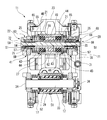
- FIG. 1 is an exploded perspective view of a disc brake according to a first embodiment of the present invention.
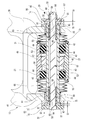
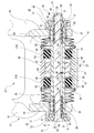
- FIG. 2 is a vertical sectional view of the disc brake shown in FIG. 3 is a horizontal cross-sectional view of the main part of the disc brake shown in FIG.
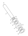
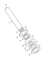
- FIG. 4 is an exploded perspective view of an inner peripheral washer and a rubber ring fitted into the guide pin shown in FIG.
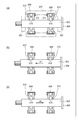
- FIG. 5 is a diagram for explaining the operation of the disc brake shown in FIG. 1.
- FIG. 5 (a) is a diagram for explaining the operation at the time of initializing
- FIG. 5 (b) is a diagram for explaining the operation at the time of brake braking
- c) is an operation explanatory diagram when the brake is slowly opened.
- FIG. 5 (a) is a diagram for explaining the operation at the time of initializing
- FIG. 5 (b) is a diagram for explaining the operation at the time of brake braking
- c) is an operation explanatory diagram when the brake is slowly opened.
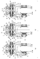
- FIG. 6 is a horizontal sectional view of an essential part of a disc brake according to a second embodiment of the present invention.
- FIG. 7 is an exploded perspective view of an inner peripheral washer and a rubber ring fitted into the guide pin shown in FIG.
- FIG. 8 is a horizontal sectional view of an essential part of a disc brake according to a third embodiment of the present invention.
- FIG. 9 is an exploded perspective view of an inner peripheral washer and a rubber ring fitted into the guide pin shown in FIG.
- FIG. 10 is a horizontal sectional view of an essential part of a disc brake according to a fourth embodiment of the present invention.
- FIG. 11 is an exploded perspective view of the inner peripheral washer and the rubber ring fitted into the guide pin shown in FIG.
- FIG. 12A is a schematic diagram showing the posture of the retraction rubber ring with respect to the guide pin during non-braking in the conventional configuration
- FIG. 12B is a diagram of the retraction rubber ring during braking in FIG.
- FIG. 12 (c) is a schematic diagram showing the action of the retraction rubber ring during repositioning.
- the floating caliper type disc brake 11 according to the first embodiment of the present invention will be described by taking as an example a case of being used for a railcar disc brake.
- the disc brake 11 can be suitably used in various industrial drive device brake devices that generate a braking force on a rotating member such as an elevator.
- the floating caliper type disc brake 11 includes a wheel 35 (see (a) to (c) of FIG. 5) from a base 25 slidably supported on a support 23 coupled to a carriage frame (not shown).
- the floating caliper 13 has a piston-side pressing arm 39 and a counter-piston-side pressing arm 41 which are a pair of pressing arms extended to positions sandwiching the disk rotors 37, 37 attached to both side surfaces of the reference) from both sides in the axial direction.
- a pair of brake pads 17 and 17 provided on the piston-side pressing arm 39 and the anti-piston-side pressing arm 41 so as to face the outer surfaces of the disk rotors 37 and 37, respectively, and a piston-side pressing arm 39.
- the caliper return arranged at both ends of the drive piston 15 (see the partially broken portion in FIG. 5A) and the upper guide pin (guide pin) 31 It has a mechanism 20, 22 as main components.
- the upper guide pin 31 is formed as a hollow pipe.
- An upper guide pin 31 that is a guide pin with respect to an upper cylindrical support portion 27 and a lower cylindrical support portion 29 that are a pair of upper and lower cylindrical support portions of the support 23 are provided above and below the base portion 25 in the floating caliper 13.
- Lower guide pins 33 are spanned.
- the base 25 of the floating caliper 13 is slidably supported on the upper cylindrical support 27 and the lower cylindrical support 29 via the upper guide pin 31 and the lower guide pin 33. Both ends of the upper guide pin 31 are prevented from coming off from the base portion 25 by caliper return mechanisms 20 and 22.
- the lower guide pin 33 is fixed to the base portion 25 by a flange 34 and a nut 36.
- the base portion 25 of the floating caliper 13 is a pair of pressing arms up to a position sandwiching the disk rotor 37 attached to both sides of the wheel 35 (see FIGS. 5A to 5C) from both sides in the axial direction.
- the piston side pressing arm 39 and the anti-piston side pressing arm 41 are extended. Note that the piston-side pressing arm 39 and the anti-piston-side pressing arm 41 in the first embodiment are each composed of a bifurcated arm portion.
- the brake pads 17 are provided at the tip portions of the piston-side pressing arm 39 and the anti-piston-side pressing arm 41 so as to face the outer surface of the disc rotor 37 attached to both side surfaces of the wheel 35.
- a structure in which the lining surface of the brake pad 17 presses the disc rotor 37 to perform a brake operation will be described as an example.
- the disc brake 11 may be configured to brake by directly pressing both side surfaces of the wheel 35.
- the drive piston 15 is provided on a piston-side pressing arm 39 that is one of a pair of pressing arms in order to drive one of the brake pads 17 toward the side surface of the disc rotor 37.
- the caliper return mechanisms 20 and 22 are disposed at both ends of the upper guide pin 31 in the first embodiment.
- the caliper return mechanism 20 elastically biases the base portion 25 slidably supported with respect to the upper guide pin 31 to the drive piston side, and the caliper return mechanism 22 elastically applies the base portion 25 to the side opposite to the drive piston side. Rush.
- the caliper return mechanism according to the present invention is provided at least at the end (the left end in FIG. 3) opposite to the drive piston side at both ends of the upper guide pin 31 like the caliper return mechanism 22. Good.
- the caliper return mechanisms 20 and 22 are provided only on the upper guide pin 31 will be described.
- the caliper return mechanisms 20 and 22 are provided on both the upper guide pin 31 and the lower guide pin 33. It may be provided.
- the caliper return mechanism 20 includes a spring housing member 59 mounted on a spring housing portion 69 provided in a piston side end opening (end portion) 38 of a hollow upper guide pin 31, and an upper guide pin.
- a compression spring member 65 interposed between the bottom portion 58.
- the spring accommodating member 59 is formed in a bottomed cylindrical shape and has an open end flange 57 on the open end side.
- the caliper return mechanism 22 has a spring accommodating member 59 attached to a spring accommodating portion 69 provided in the opposite piston end opening (end) 32 of the hollow upper guide pin 31 and the upper guide pin 31.
- a sliding bearing 61 for slidably supporting the base 25, a spring receiving member 63 covering the opening of the upper guide pin 31 serving as the spring accommodating portion 69, a spring receiving member 63, and a bottom 58 of the spring accommodating member 59 A compression spring member 65 interposed therebetween.
- the spring accommodating member 59 is attached to a spring accommodating portion 69 that is recessed in the piston side end opening 38 and the anti-piston side end opening (end portion) 32 of the upper guide pin 31, respectively.
- the opening end flange 57 is locked to the opening edge of the spring accommodating portion 69, and further insertion into the spring accommodating portion 69 is restricted.
- the compression spring member 65 may be an elastic member such as rubber.
- the sliding bearing 61 is formed in a cylindrical shape, is fitted into the guide pin support portion 71 of the spring receiving members 63 and 66, and is disposed between the upper guide pin 31 and the spring receiving members 63 and 66.
- the slide bearing 61 reduces the sliding resistance of the base portion 25 with respect to the upper guide pin 31. Therefore, spring receiving members 63 and 66 are slidably fitted on the outer peripheral sides of both ends of the upper guide pin 31.
- the spring receiving member 66 includes a cylindrical guide pin support portion 71 and an annular spring support portion 68.
- the spring receiving member 63 has a cylindrical guide pin support portion 71 and an annular spring support portion 72.
- the guide pin support portion 71 is formed in a cylindrical shape, and is fixed to the base portion 25 so as to slidably support the upper guide pin 31 via the slide bearing 61. Further, between the guide pin support portion 71 and the base portion 25, there is provided a detent mechanism for restricting relative rotation of each other by engaging the notch portion 76 of the collar portion 75 with the locking rib 78 of the base portion 25. It has been.
- the spring support 68 and the spring support 72 are respectively in contact with the opening 56 at the bottom 58 of the spring housing member 59 so as to cover the outer opening end of the guide pin support 71 while being in contact with one end of the compression spring member 65. It is fixed to the base 25 together with the guide pin support portion 71 by a bolt shaft 62 penetrating through the hollow upper guide pin 31 in the central axis direction and a nut 70 screwed to the tip of the bolt shaft 62. Thereby, the spring receiving members 63 and 66 are fixed integrally with the base portion 25. The spring receiving members 63 and 66 fixed integrally with the base portion 25 are slidable on the upper guide pin 31 via the sliding bearing 61.
- the base 25 is slidably supported with respect to the upper guide pin 31 via the spring receiving members 63 and 66.
- the spring support portions 72 and 68 are removed while the guide pin support portions 71 of the spring receiving members 63 and 66 fixed to the base portion 25 of the floating caliper 13 are slidably supported on the outer periphery of the upper guide pin 31.
- the compression spring member 65 can be attached and detached.
- the return force and return amount of the floating caliper 13 can be adjusted very easily by replacing the spring support portions 72 and 68 and the compression spring member 65 with different specifications (predetermined interval S1, spring constant, etc.). Become.
- an O-ring 80 is mounted between the washer 84 tightened by the nut 70 and the spring support portion 68, and the O-ring is interposed between the spring support portion 68 and the flange portion 75 of the guide pin support portion 71.
- 81 is mounted.
- an O-ring 82 is mounted between the bolt head 64 of the bolt shaft 62 and the spring support portion 72, and an O-ring 81 is interposed between the spring support portion 72 and the flange portion 75 of the guide pin support portion 71. Is installed.
- the O-rings 80 and 82 seal the through holes of the spring support portions 68 and 72 through which the bolt shaft 62 passes, respectively, and the O-ring 81 is provided between the guide pin support portion 71 and the spring support portions 68 and 72.
- the mating portion is sealed in a watertight manner to prevent water and dust from entering the spring accommodating portion 69 and the spring accommodating member 59.
- the notch portion 74 of the spring support portion 72 engages with the locking projection 77 of the flange portion 75, thereby restricting relative rotation of each other.
- a stop mechanism is provided between the spring support portion 72 and the bolt shaft 62.
- a bolt head 64 having a two-sided width is fitted into the fitting recess 73 of the spring support portion 72 so as to restrict relative rotation of each other. Is provided. Therefore, when the nut 70 is screwed onto the tip of the bolt shaft 62, the bolt shaft 62 does not idle and the assembly workability is improved.
- the compression spring member 65 is housed inside the spring housing member 59, as shown in FIGS. One end of the compression spring member 65 accommodated in each spring accommodating member 59 abuts on the bottom 58 of the spring accommodating member 59 and the other end is the spring support portion 72 of the spring receiving member 63 (or the spring support of the spring receiving member 66). Part 68).
- Each compression spring member 65 includes a spring receiving member 66 (or a spring receiving member 63) in a state having a predetermined interval S1 with respect to the open end flange 57 of the spring accommodating member 59, and a bottom 58 of the spring accommodating member 59. It is inserted between.
- the caliper returning mechanisms 20 and 22 have a stopper portion 85 (see FIG. 3).
- the stopper portion 85 is formed in a step shape on the inner periphery of the guide pin support portion 71.
- the stopper portion 85 abuts against the opening end flange 57 of the spring housing member 59 to restrict the movement of the spring housing member 59 in the axial direction with respect to the base portion 25 via the guide pin support portion 71 at a predetermined interval S1. That is, the movement of the spring housing member 59 in the caliper return mechanisms 20 and 22 is restricted to the predetermined interval S1 by the stopper portion 85 of the guide pin support portion 71 in the spring receiving member 66 (or the spring receiving member 63).
- a pair of rubber rings 21 that elastically support the upper guide pin 31 in the radial direction are fitted inside the upper cylindrical support portion 27 of the support 23.
- inner peripheral side washers 44 fitted into the upper guide pins 31 are arranged on the both sides in the axial direction of the rubber ring 21.
- the inner peripheral side washer 44 is configured such that the outer peripheral side washer 43 fixed to the inner peripheral surface of the upper cylindrical support portion 27 comes into contact with the surface of the inner peripheral side washer 44 opposite to the surface that contacts the rubber ring 21. Movement along the axial direction of the upper guide pin 31 is restricted. That is, the outer peripheral washer 43 restricts movement in the direction along the upper guide pin 31 of the rubber ring 21 via the inner peripheral washer 44.
- a centering bearing 49 is fixed by a step 45 and a snap ring 47 at the center of the inner peripheral surface of the upper cylindrical support 27 surrounding the upper guide pin 31.
- the aligning bearing 49 supports the upper guide pin 31 in a swingable manner.
- the upper guide pin 31 and the upper cylindrical support portion 27 of the support 23 are not connected to each other because the wheel 35 elastically supported by the carriage frame is displaced (swing) relative to the carriage frame. Even if they are parallel, the sliding surfaces of the brake pad 17 and the disk rotor 37 can be brought into close contact with each other during braking.
- a rubber bush 52 and a sleeve 51 are interposed between the lower guide pin 33 and the lower cylindrical support portion 29 as shown in FIG.
- the lower guide pin 33 is supported slidably in the axial direction with respect to the lower cylindrical support portion 29 via the rubber bush 52 and the sleeve 51 instead of the aligning bearing 49.
- the pair of rubber rings 21 are disposed on both sides in the axial direction of the aligning bearing 49 on the inner peripheral surface of the upper cylindrical support portion 27.
- the pair of rubber rings 21 are slidably fitted to the upper cylindrical support portion 27 and elastically support the upper guide pin 31 in the radial direction.
- each rubber ring 21 has a stepped portion 53 formed on the inner peripheral surface of the upper cylindrical support portion 27 via an inner peripheral side washer 44 and an outer peripheral side washer 43.
- the pair of rubber rings 21 are fixed to the inner peripheral surface of the upper cylindrical support portion 27 in a state where movement in the axial direction is restricted.
- a rubber ring 21 having a shape and material having a high elastic range (deformation amount) is selected.
- the cross-sectional shape of the surface including the axis of the rubber ring 21 is a rectangular shape. As shown in FIG. 3, the rubber ring 21 is in sliding contact with the outer peripheral surface of the upper guide pin 31 on the inner peripheral surface side.
- the cross-sectional shape of the rubber ring according to the present invention is not limited to the rectangular cross section of the rubber ring 21 in the first embodiment, but a U-shaped cross section having an annular groove that can hold grease on the inner peripheral surface. Various shapes such as a cross section and an H-shaped section can be adopted.
- the sliding resistance value between the inner peripheral surface of the rubber ring and the outer peripheral surface of the upper guide pin 31 is set to an appropriate value of 5 to 50 kgf. Therefore, high-performance grease mixed with solidified lubricant such as molybdenum disulfide can be held.
- solidified lubricant such as molybdenum disulfide
- the inner periphery of the rubber ring 21 is in sliding contact with the outer peripheral surface of the upper guide pin 31, but the inner ring washer 44 is disposed on both sides in the axial direction of the rubber ring 21 and inserted into the upper guide pin 31.
- the inner peripheral portion is restricted from being bent and deformed along the axial direction of the upper guide pin 31. Therefore, the rubber ring 21 has an inner peripheral portion along the axial direction of the upper guide pin 31 due to the movement of the upper guide pin 31 during braking as in the conventional retraction rubber ring 513 (see FIG. 12B).
- the rubber ring 21 elastically supports the upper guide pin 31 only in the radial direction.
- the drive piston side is opposite (hereinafter referred to as the anti-drive piston side).
- the rubber ring 21 does not produce a force for returning the upper guide pin 31 to the above, but only the caliper returning force of the caliper returning mechanism 20 acts.
- the force relationship necessary for the caliper returning force is as follows. That is, F1: sliding resistance of the upper guide pin 31 and the support 23 (aligning bearing 49, rubber ring 21), F2: spring force of the compression spring member 65, F3: lower guide pin 33 and the support 23 (sleeve 51) Sliding resistance, F4: When the sliding resistance of the sliding bearing 61 at both ends of the upper guide pin 31 is set, F1>F2> (F3 + F4) It is set so as to have a power relationship of
- the floating caliper 13 is such that the base 25 on the side opposite to the piston side pressing arm 41 has a spring bearing on the side opposite to the driving piston (right side in FIG. 5B).
- the member 63 is moved in a direction to approach the disc rotor 37 (leftward in FIG. 5B), and the base 25 on the piston side pressing arm 39 side is left on the driving piston side (left side in FIG. 5B).
- Spring receiving member 66 is moved away from the disc rotor 37 (leftward in FIG. 5B).
- the caliper return force is accumulated in the caliper return mechanism 22 disposed on the counter drive piston side.
- the compression spring member 65 When the compression spring member 65 is compressed, the spring receiving member 63 moves on the outer periphery of the upper guide pin 31 with sliding resistance reduced in the direction along the axis by the slide bearing 61. Due to the movement of the spring receiving member 63, the spring support portion 72 on the counter drive piston side is locked to the counter piston side end opening 32 (see FIG. 3) of the upper guide pin 31 as shown in FIG. It abuts on the open end flange 57.
- the piston side pressing arm 39 moves the spring receiving member 66 on the driving piston side in a direction away from the disk rotor 37. Then, the spring accommodating member 59 on the drive piston side is moved in a direction in which the opening end flange 57 is pressed by the stopper portion 85 of the spring receiving member 66 and is pulled out from the spring accommodating portion 69 of the upper guide pin 31. Thereby, a gap (interference avoidance gap) S2 is formed between the opening end flange 57 and the piston side end opening 38 (see FIG. 3) of the upper guide pin 31.
- the opening end flange 57 remains in contact with the stopper portion 85 due to the urging force of the compression spring member 65 and is separated from the spring support portion 68. Therefore, the compression spring member 65 on the drive piston side is arranged. Does not affect the compression deformation of the compression spring member 65 on the counter-drive piston side. The above is the state at the time of brake braking.
- the piston side pressing arm 39 moves the spring receiving member 66 on the driving piston side in a direction to approach the disk rotor 37.
- the interference avoidance gap S2 is formed between the opening end flange 57 and the piston side end opening 38 of the upper guide pin 31. For this reason, the elastic force of the compression spring member 65 on the drive piston side does not act as a reaction force (load) against the caliper return force.
- the clearance d between each brake pad 17 and the disc rotor 37 is set to 3 mm before braking (at the time of initializing).
- the compression spring member 65 on the counter drive piston side is compressed and deformed. The restoring force due to the deformation of the compression spring member 65 creates a force (retraction effect) for returning the floating caliper 13.
- the operation of the disc brake 11 having the above-described structure when the wheel is swung will be described.
- the wheel 35 swings with respect to the floating caliper 13 fixed to the carriage frame during braking during curve traveling.
- the clearance of both brake pads 17 is maintained at the same value even after the wheel is swung as long as the amount of wheel swing is twice the pad clearance.
- the floating caliper type disc brake 11 of the first embodiment can secure both pad clearances of 3 mm up to a wheel swing amount of ⁇ 6 mm.
- the pressing force of the brake pad 17 against the disc rotor 37 is generated by the compression deformation of the compression spring member 65 on the drive piston side. That is, when the wheel 35 swings 6 mm in the direction of the drive piston from the initial time when the wheel 35 is initialized, the displacement amount between the support 23 and the base portion 25 becomes 3 mm, and the displacement amount between the wheel 35 and the base portion 25 becomes 3 mm. .
- a return force of 3 mm is generated in the caliper return mechanism 20 on the drive piston side. If the disc brake 11 is released from the swinging, it is possible to secure a pad clearance of 3 mm.
- the disc brake 11 at the initial time has a displacement amount of 7 mm between the support 23 and the base portion 25 and a deviation amount between the wheel 35 and the base portion 25 becomes 3 mm. . Therefore, when the wheel return amount is 6 mm, the shift amount between the support 23 and the base portion 25 is 4 mm, and the shift amount between the wheel 35 and the base portion 25 is 0 mm.
- the pad clearance between the disc rotor 37 and the brake pad 17 is 3 mm.
- the wheel return amount is 9 mm
- the amount of deviation between the support 23 and the base portion 25 is 4 mm
- the amount of deviation between the wheel 35 and the base portion 25 is 0 mm.
- the remaining amount of movement of the wheel 35 is 1 mm, and the disc rotor 37 contacts the brake pad 17.
- the compression spring member 65 on the drive piston side bends, and a pressing force of the brake pad 17 against the disc rotor 37 is generated.
- the base portion 25 of the floating caliper 13 is slidable with respect to the upper cylindrical support portion 27 of the support 23.
- Caliper return mechanisms 20 and 22 are provided at both ends of the upper guide pin 31 to be supported.
- the caliper return mechanism 22 on the counter drive piston side generates a caliper return force between the upper guide pin 31 and the floating caliper 13. Therefore, the caliper return mechanism 22 on the counter-drive piston side separates the pair of brake pads 17 from the disc rotor 37 with the same clearance as before braking by the caliper return force when the brake is released.
- the upper guide pin 31 provided with the caliper return mechanisms 20 and 22 only needs to be replaced with the upper guide pin in the existing floating caliper, and there is no additional modification to the existing floating caliper. Improvements can be made to realize pad drag countermeasures against the brake.
- the rubber rings 21 that are fitted inwardly of the upper cylindrical support portion 27 and elastically support the upper guide pins 31 in the radial direction are arranged on both sides in the axial direction of the rubber rings 21 and are inserted into the upper guide pins 31.
- the inner peripheral washer 44 is configured to restrict the inner peripheral portion from being bent and deformed along the axial direction of the upper guide pin 31. Therefore, the rubber ring 21 has an inner peripheral portion in the axial direction of the upper guide pin 31 due to the movement of the upper guide pin 31 during braking, like a conventional retraction rubber ring 513 (see FIG. 12B). Therefore, the upper guide pin 31 is not moved in the axial direction by the elastic restoring force. Accordingly, the caliper return mechanisms 20 and 22 can stably generate the caliper return force without being affected by variations in the frictional resistance of the rubber ring 21 that elastically supports the upper guide pin 31 in the radial direction.
- the inner peripheral washer 44 fitted into the upper guide pin 31 is fixed by the outer peripheral washer 43 fixed to the inner peripheral surface of the upper cylindrical support portion 27.
- the upper guide pin 31 is positioned with respect to the axial direction.
- the inner washer 44 inserted into the upper guide pin 31 has a clearance with respect to the inner peripheral surface of the upper cylindrical support portion 27 and is fixed to the inner peripheral surface of the upper cylindrical support portion 27.
- the side washer 43 has a clearance with respect to the outer peripheral surface of the upper guide pin 31. Therefore, the inner peripheral washer 44 positioned in the axial direction by the outer peripheral washer 43 can follow the movement of the upper guide pin 31 in the radial direction by slipping at the surface contact portion with the outer peripheral washer 43. it can.
- the caliper returning mechanisms 20 and 22 are disposed at both ends of the upper guide pin 31, for example, the counter-driving required when the wheel 35 swings is performed. It is possible to create a force for returning the base portion 25 of the floating caliper 13 to the piston side. Since the inner peripheral side washers 44 of the first embodiment are disposed on both axial sides of the rubber ring 21, not only the deformation of the rubber ring 21 due to the movement of the upper guide pin 31 during braking, but also the above-described wheels. The bending deformation of the rubber ring 21 due to the movement of the upper guide pin 31 in the opposite direction when the floating caliper 13 is moved by the swinging of the 35 can also be restricted.
- the brake pads 17 are pressed against the disc rotors 37 attached to both side surfaces of the railcar wheel 35 for braking. In doing so, the pad clearance between the brake pad 17 and the disc rotor 37 can be maintained constant. As a result, it is possible to prevent uneven wear and drag of the brake pad 17 and to suppress an increase in the starting torque of the vehicle.
- the floating caliper type disc brake 111 according to the second embodiment the same members as those in the floating caliper type disc brake 11 according to the first embodiment are denoted by the same reference numerals, and redundant description is omitted.
- the floating caliper type disc brake 111 according to the second embodiment is provided on the inner peripheral surface 21 a of the rubber ring 21 ⁇ / b> A fitted inside the upper cylindrical support portion 27.
- a fitting member 50 interposed between the upper guide pin 31 and the upper guide pin 31 is disposed.
- the fitting member 50 is a cylindrical member made of metal or resin, and has a slit 54. Then, the fitting member 50 is fitted and inserted along the inner peripheral surface 21a of the rubber ring 21A in a state of being elastically deformed in the reduced diameter direction. Therefore, the fitting member 50 fitted and inserted into the inner peripheral surface 21a of the rubber ring 21A can be fitted with the upper guide pin 31 with an allowance.
- the fitting member 50 is interposed between the inner peripheral surface 21a of the rubber ring 21A and the upper guide pin 31, so that the rubber The sliding resistance of the upper guide pin 31 with respect to the ring 21 ⁇ / b> A is stabilized, the width of the axial force fluctuation is reduced when the upper guide pin 31 slides, and the caliper returning force of the caliper returning mechanisms 20 and 22 is stabilized. Further, since the fitting member 50 fitted on the inner peripheral surface 21a of the rubber ring 21A can be fitted with the upper guide pin 31 with a tightening margin, the upper guide pin 31 has a sliding resistance against the rubber ring 21A. Is more stable.
- the floating caliper type disc brake 211 according to the third embodiment is provided on the inner peripheral surface 21 a of the rubber ring 21 ⁇ / b> A fitted inside the upper cylindrical support portion 27.
- a fitting member 50B interposed between the upper guide pin 31 and the upper guide pin 31 is disposed.
- the inner peripheral end of the inner peripheral washer 46 has a cylindrical extending portion 48 extending along the inner peripheral surface 21a of the rubber ring 21A.
- the fitting member 50 ⁇ / b> B is a cylindrical member made of metal or resin, and has a slit 54.
- the fitting member 50B is inserted and inserted along the inner peripheral surface 21a of the rubber ring 21A in a state of being elastically deformed in the diameter reducing direction. Therefore, the fitting member 50B fitted on the inner peripheral surface 21a of the rubber ring 21A can be fitted with the upper guide pin 31 with a tightening margin.
- the inner peripheral washer 46 has a cylindrical extension 48 formed by bending the inner peripheral end of the annular inner peripheral washer into an L-shaped cross section by, for example, burring.
- the pair of inner peripheral side washers 46 are fitted to the inner peripheral surface 21a of the rubber ring 21A so that the extending portions 48 sandwich the fitting member 50B fitted and inserted into the rubber ring 21A from both opening end sides. That is, the inner washer 46 and the fitting member 50B are fitted to the inner circumferential surface 21a of the rubber ring 21A by the extending portion 48, and the positions thereof are determined in advance. Therefore, it is not necessary to perform positioning when the upper guide pin 31 is assembled to the upper cylindrical support portion 27 of the support 23, and the assemblability is good.
- the opening edge of the inner peripheral side washer 46 has an R portion in which the entrance is bent rather than the edge by the cylindrical extending portion 48, so that the inner peripheral side washer 46 is inserted into the upper guide pin 31.
- the upper guide pin 31 can be smoothly inserted without being caught by the inner peripheral washer 46.
- the floating caliper type disc brake 311 according to the fourth embodiment includes a rubber ring 21B fitted inside the upper cylindrical support portion 27, and a shaft of the rubber ring 21B. And inner washers 46 disposed on both sides in the direction.
- the rubber ring 21B has an annular protrusion 21b that protrudes from the axially central portion of the inner peripheral surface 21a.
- the inner peripheral washer 46 has a cylindrical extending portion 48 whose inner peripheral end extends along the inner peripheral surface 21a of the rubber ring 21B. Therefore, the pair of inner peripheral washers 46 are fitted to the inner peripheral surface 21a of the rubber ring 21B so that the extended portions 48 sandwich the annular protrusion 21b of the rubber ring 21B from both opening end sides. That is, the inner peripheral washer 46 is fitted to the inner peripheral surface 21a of the rubber ring 21B by the extending portion 48, and the position is determined in advance.
- the opening edge of the inner peripheral side washer 46 has an R portion in which the entrance is bent rather than the edge by the cylindrical extending portion 48, so that the inner peripheral side washer 46 is inserted into the upper guide pin 31.
- the upper guide pin 31 can be smoothly inserted without being caught by the inner peripheral washer 46.
- the caliper return force can be easily set, and the desired caliper can be set.
- the return operation can be exhibited stably, and the brake pad 17 can be reliably prevented from being dragged.
- a base (slidably supported via a guide pin (upper guide pin 31) with respect to the cylindrical support (upper cylindrical support 27 and lower cylindrical support 29) of the support (23).
- the base portion which is disposed at least on the opposite side of the drive piston side at both ends of the guide pin and is slidably supported with respect to the guide pin, is elastically biased to the side opposite to the drive piston side.
- the rubber ring is arranged at least on the drive piston side on both sides in the axial direction of the rubber ring, and is inserted into the guide pin to restrict the inner peripheral portion of the rubber ring from being bent and deformed along the axial direction of the guide pin.
- Disc brake
- the inner peripheral end of the inner peripheral washer is The disc brake according to the above [1] or [2], wherein the disc brake has a cylindrical extension extending along the inner peripheral surface of the rubber ring.
- the fitting member is The disc brake according to the above [4], which is formed of a cylindrical member having a slit and is fitted and inserted along the inner peripheral surface of the rubber ring in a state of being elastically deformed in the diameter reducing direction.
- the inner peripheral washer is The disc brake according to any one of [1] to [5], which is disposed on both axial sides of the rubber ring.
- a railway vehicle disc brake comprising the disc brake according to any one of [1] to [6].
- this invention is not limited to embodiment mentioned above, A deformation
- the material, shape, dimensions, number, arrangement location, and the like of each component in the above-described embodiment are arbitrary and are not limited as long as the present invention can be achieved.
- This application is based on a Japanese patent application filed on March 30, 2016 (Japanese Patent Application No. 2016-068673), the contents of which are incorporated herein by reference.
- the caliper return force can be easily set, and the desired caliper return operation can be stably exhibited to reliably prevent pad dragging. Therefore, it is possible to provide a good disc brake and a railcar disc brake that can prevent an increase in starting torque and prevent lining wear.
Landscapes
- Engineering & Computer Science (AREA)
- General Engineering & Computer Science (AREA)
- Mechanical Engineering (AREA)
- Braking Arrangements (AREA)
Abstract
L'invention concerne un frein à disque (11) comprenant : une section de base (25) supportée d'une manière coulissante par une broche de guidage d'étage supérieur (31) supportée par un support (23) ; un étrier flottant (13) ayant un bras de pressage côté piston (39) et un bras de pressage (41) du côté opposé au piston ; une paire de plaquettes de frein (17) ; un piston d'entraînement (15) disposé sur le bras de pressage côté piston (39) ; un mécanisme de rappel d'étrier (22) disposé à une extrémité de la broche de guidage d'étage supérieur (31) et pressant élastiquement la section de base (25) du côté opposé au piston d'entraînement ; et des rondelles périphériques internes (44) disposées sur les deux côtés axiaux d'un anneau en caoutchouc (21) qui supporte élastiquement radialement la broche de guidage d'étage supérieur (31) et empêche la section périphérique interne de l'anneau de caoutchouc (21) de se déformer et de dévier dans la direction axiale de la broche de guidage d'étage supérieur (31).
Priority Applications (1)
| Application Number | Priority Date | Filing Date | Title |
|---|---|---|---|
| US16/089,414 US10890221B2 (en) | 2016-03-30 | 2017-03-30 | Disc brake and disc brake for railway vehicles |
Applications Claiming Priority (2)
| Application Number | Priority Date | Filing Date | Title |
|---|---|---|---|
| JP2016-068673 | 2016-03-30 | ||
| JP2016068673A JP6676437B2 (ja) | 2016-03-30 | 2016-03-30 | ディスクブレーキ及び鉄道車両用ディスクブレーキ |
Publications (1)
| Publication Number | Publication Date |
|---|---|
| WO2017170897A1 true WO2017170897A1 (fr) | 2017-10-05 |
Family
ID=59964739
Family Applications (1)
| Application Number | Title | Priority Date | Filing Date |
|---|---|---|---|
| PCT/JP2017/013323 Ceased WO2017170897A1 (fr) | 2016-03-30 | 2017-03-30 | Frein à disque et frein à disque pour véhicules ferroviaires |
Country Status (3)
| Country | Link |
|---|---|
| US (1) | US10890221B2 (fr) |
| JP (1) | JP6676437B2 (fr) |
| WO (1) | WO2017170897A1 (fr) |
Cited By (1)
| Publication number | Priority date | Publication date | Assignee | Title |
|---|---|---|---|---|
| IT202300028029A1 (it) * | 2023-12-27 | 2025-06-27 | Brembo Spa | Pinza freno del tipo flottante |
Families Citing this family (3)
| Publication number | Priority date | Publication date | Assignee | Title |
|---|---|---|---|---|
| IT202000027230A1 (it) * | 2020-11-13 | 2022-05-13 | Brembo Spa | Assieme di perno di supporto di pastiglie freno ed elemento elastico di vincolo assiale, pinza freno e metodo di interazione di un perno di supporto per pastiglie ed un elemento elastico di vincolo assiale |
| CN115467914B (zh) * | 2021-06-10 | 2024-06-04 | 盐城市步高汽配制造有限公司 | 一种汽车辅助制动系统 |
| WO2024155368A1 (fr) * | 2023-01-18 | 2024-07-25 | Hendrickson Usa, L.L.C. | Ensemble tige de guidage de cisaillement à couple pour véhicules utilitaires lourds |
Citations (5)
| Publication number | Priority date | Publication date | Assignee | Title |
|---|---|---|---|---|
| JPH0448438U (fr) * | 1990-08-30 | 1992-04-24 | ||
| JPH0632773U (ja) * | 1992-09-30 | 1994-04-28 | 曙ブレーキ工業株式会社 | フローティングキャリパ型ディスクブレーキ |
| JPH08270690A (ja) * | 1995-03-31 | 1996-10-15 | Akebono Brake Ind Co Ltd | ディスクブレーキのパッド戻し構造 |
| JPH11263223A (ja) * | 1998-03-17 | 1999-09-28 | Akebono Brake Ind Co Ltd | キャリパブレーキ |
| US20080093181A1 (en) * | 2006-10-19 | 2008-04-24 | Waag James R | Brake caliper guide pin assembly |
Family Cites Families (8)
| Publication number | Priority date | Publication date | Assignee | Title |
|---|---|---|---|---|
| JP4566170B2 (ja) | 2006-08-23 | 2010-10-20 | カヤバ工業株式会社 | 鉄道車両用キャリパブレーキ装置 |
| JP5156325B2 (ja) * | 2007-10-11 | 2013-03-06 | カヤバ工業株式会社 | 車両用キャリパブレーキ装置 |
| JP5677915B2 (ja) * | 2011-09-06 | 2015-02-25 | カヤバ工業株式会社 | キャリパブレーキ装置 |
| JP5622757B2 (ja) * | 2012-02-06 | 2014-11-12 | カヤバ工業株式会社 | キャリパブレーキ装置 |
| JP5822134B2 (ja) * | 2012-02-06 | 2015-11-24 | Kyb株式会社 | キャリパブレーキ装置 |
| JP5845153B2 (ja) * | 2012-08-06 | 2016-01-20 | Kyb株式会社 | キャリパブレーキ装置 |
| JP6012490B2 (ja) * | 2013-01-25 | 2016-10-25 | Kyb株式会社 | キャリパブレーキ装置 |
| US9694833B2 (en) * | 2014-12-04 | 2017-07-04 | Akebono Brake Industry Co., Ltd. | Disk brake and disk brake for railway vehicle |
-
2016
- 2016-03-30 JP JP2016068673A patent/JP6676437B2/ja active Active
-
2017
- 2017-03-30 WO PCT/JP2017/013323 patent/WO2017170897A1/fr not_active Ceased
- 2017-03-30 US US16/089,414 patent/US10890221B2/en not_active Expired - Fee Related
Patent Citations (5)
| Publication number | Priority date | Publication date | Assignee | Title |
|---|---|---|---|---|
| JPH0448438U (fr) * | 1990-08-30 | 1992-04-24 | ||
| JPH0632773U (ja) * | 1992-09-30 | 1994-04-28 | 曙ブレーキ工業株式会社 | フローティングキャリパ型ディスクブレーキ |
| JPH08270690A (ja) * | 1995-03-31 | 1996-10-15 | Akebono Brake Ind Co Ltd | ディスクブレーキのパッド戻し構造 |
| JPH11263223A (ja) * | 1998-03-17 | 1999-09-28 | Akebono Brake Ind Co Ltd | キャリパブレーキ |
| US20080093181A1 (en) * | 2006-10-19 | 2008-04-24 | Waag James R | Brake caliper guide pin assembly |
Cited By (2)
| Publication number | Priority date | Publication date | Assignee | Title |
|---|---|---|---|---|
| IT202300028029A1 (it) * | 2023-12-27 | 2025-06-27 | Brembo Spa | Pinza freno del tipo flottante |
| WO2025141402A1 (fr) * | 2023-12-27 | 2025-07-03 | Brembo S.P.A. | Étrier de frein de type flottant |
Also Published As
| Publication number | Publication date |
|---|---|
| JP6676437B2 (ja) | 2020-04-08 |
| US20200300311A1 (en) | 2020-09-24 |
| US10890221B2 (en) | 2021-01-12 |
| JP2017180661A (ja) | 2017-10-05 |
Similar Documents
| Publication | Publication Date | Title |
|---|---|---|
| WO2017170897A1 (fr) | Frein à disque et frein à disque pour véhicules ferroviaires | |
| JP5184693B2 (ja) | ディスクブレーキ | |
| WO2011126125A1 (fr) | Frein à disque de type à étrier flottant, son procédé d'assemblage et sous-ensembles constitués d'attaches de patin et de ressorts de rappel | |
| WO2015190495A1 (fr) | Ensemble plaquette pour frein à disque | |
| JPS6044529B2 (ja) | 円板ブレーキ | |
| US4498564A (en) | Disc brake subassembly having friction pad retaining means | |
| JP6719171B2 (ja) | フローティングキャリパ型ディスクブレーキ装置及び鉄道車両用ディスクブレーキ装置 | |
| JP5016492B2 (ja) | 摩擦部材及びディスクブレーキ | |
| JP2005106291A (ja) | ブレーキキャリパ | |
| JP2000220670A (ja) | ディスクブレーキ | |
| US9694833B2 (en) | Disk brake and disk brake for railway vehicle | |
| US20220299074A1 (en) | Brake assembly | |
| JP6599730B2 (ja) | ディスクブレーキ及び鉄道車両用ディスクブレーキ | |
| JPWO2019003735A1 (ja) | ディスクブレーキ | |
| US20200325946A1 (en) | Brake disc for a disc brake and method | |
| US5638928A (en) | Brake center tracking roller and cam arrangement | |
| JP6416013B2 (ja) | ディスクブレーキ及び鉄道車両用ディスクブレーキ | |
| JP2022024201A (ja) | ディスクブレーキ、摩擦パッドおよびシム | |
| CN112324821B (zh) | 用于车辆制动器的制动卡钳 | |
| KR101405201B1 (ko) | 차량용 디스크 브레이크 | |
| JPWO2019012805A1 (ja) | ディスクブレーキ | |
| JP6708004B2 (ja) | ダンパ装置 | |
| US20180180120A1 (en) | Brake module | |
| JP6149273B2 (ja) | ディスクブレーキ | |
| JPH085399Y2 (ja) | ピンスライド型ディスクブレーキ |
Legal Events
| Date | Code | Title | Description |
|---|---|---|---|
| NENP | Non-entry into the national phase |
Ref country code: DE |
|
| 121 | Ep: the epo has been informed by wipo that ep was designated in this application |
Ref document number: 17775431 Country of ref document: EP Kind code of ref document: A1 |
|
| 122 | Ep: pct application non-entry in european phase |
Ref document number: 17775431 Country of ref document: EP Kind code of ref document: A1 |