WO2017171013A1 - 方向性電磁鋼板 - Google Patents
方向性電磁鋼板 Download PDFInfo
- Publication number
- WO2017171013A1 WO2017171013A1 PCT/JP2017/013622 JP2017013622W WO2017171013A1 WO 2017171013 A1 WO2017171013 A1 WO 2017171013A1 JP 2017013622 W JP2017013622 W JP 2017013622W WO 2017171013 A1 WO2017171013 A1 WO 2017171013A1
- Authority
- WO
- WIPO (PCT)
- Prior art keywords
- groove
- steel sheet
- protrusion
- height
- grain
- Prior art date
- Legal status (The legal status is an assumption and is not a legal conclusion. Google has not performed a legal analysis and makes no representation as to the accuracy of the status listed.)
- Ceased
Links
Images






Classifications
-
- C—CHEMISTRY; METALLURGY
- C21—METALLURGY OF IRON
- C21D—MODIFYING THE PHYSICAL STRUCTURE OF FERROUS METALS; GENERAL DEVICES FOR HEAT TREATMENT OF FERROUS OR NON-FERROUS METALS OR ALLOYS; MAKING METAL MALLEABLE, e.g. BY DECARBURISATION OR TEMPERING
- C21D8/00—Modifying the physical properties of ferrous metals or ferrous alloys by deformation combined with, or followed by, heat treatment
- C21D8/12—Modifying the physical properties of ferrous metals or ferrous alloys by deformation combined with, or followed by, heat treatment during manufacturing of articles with special electromagnetic properties
- C21D8/1216—Modifying the physical properties of ferrous metals or ferrous alloys by deformation combined with, or followed by, heat treatment during manufacturing of articles with special electromagnetic properties characterised by the working steps
- C21D8/1222—Hot rolling
-
- H—ELECTRICITY
- H01—ELECTRIC ELEMENTS
- H01F—MAGNETS; INDUCTANCES; TRANSFORMERS; SELECTION OF MATERIALS FOR THEIR MAGNETIC PROPERTIES
- H01F1/00—Magnets or magnetic bodies characterised by the magnetic materials therefor; Selection of materials for their magnetic properties
- H01F1/01—Magnets or magnetic bodies characterised by the magnetic materials therefor; Selection of materials for their magnetic properties of inorganic materials
- H01F1/03—Magnets or magnetic bodies characterised by the magnetic materials therefor; Selection of materials for their magnetic properties of inorganic materials characterised by their coercivity
- H01F1/12—Magnets or magnetic bodies characterised by the magnetic materials therefor; Selection of materials for their magnetic properties of inorganic materials characterised by their coercivity of soft-magnetic materials
- H01F1/14—Magnets or magnetic bodies characterised by the magnetic materials therefor; Selection of materials for their magnetic properties of inorganic materials characterised by their coercivity of soft-magnetic materials metals or alloys
- H01F1/147—Alloys characterised by their composition
-
- B—PERFORMING OPERATIONS; TRANSPORTING
- B23—MACHINE TOOLS; METAL-WORKING NOT OTHERWISE PROVIDED FOR
- B23K—SOLDERING OR UNSOLDERING; WELDING; CLADDING OR PLATING BY SOLDERING OR WELDING; CUTTING BY APPLYING HEAT LOCALLY, e.g. FLAME CUTTING; WORKING BY LASER BEAM
- B23K26/00—Working by laser beam, e.g. welding, cutting or boring
- B23K26/36—Removing material
- B23K26/362—Laser etching
- B23K26/364—Laser etching for making a groove or trench, e.g. for scribing a break initiation groove
-
- B—PERFORMING OPERATIONS; TRANSPORTING
- B32—LAYERED PRODUCTS
- B32B—LAYERED PRODUCTS, i.e. PRODUCTS BUILT-UP OF STRATA OF FLAT OR NON-FLAT, e.g. CELLULAR OR HONEYCOMB, FORM
- B32B15/00—Layered products comprising a layer of metal
- B32B15/04—Layered products comprising a layer of metal comprising metal as the main or only constituent of a layer, which is next to another layer of the same or of a different material
-
- B—PERFORMING OPERATIONS; TRANSPORTING
- B32—LAYERED PRODUCTS
- B32B—LAYERED PRODUCTS, i.e. PRODUCTS BUILT-UP OF STRATA OF FLAT OR NON-FLAT, e.g. CELLULAR OR HONEYCOMB, FORM
- B32B3/00—Layered products comprising a layer with external or internal discontinuities or unevennesses, or a layer of non-planar shape; Layered products comprising a layer having particular features of form
- B32B3/26—Layered products comprising a layer with external or internal discontinuities or unevennesses, or a layer of non-planar shape; Layered products comprising a layer having particular features of form characterised by a particular shape of the outline of the cross-section of a continuous layer; characterised by a layer with cavities or internal voids ; characterised by an apertured layer
- B32B3/30—Layered products comprising a layer with external or internal discontinuities or unevennesses, or a layer of non-planar shape; Layered products comprising a layer having particular features of form characterised by a particular shape of the outline of the cross-section of a continuous layer; characterised by a layer with cavities or internal voids ; characterised by an apertured layer characterised by a layer formed with recesses or projections, e.g. hollows, grooves, protuberances, ribs
-
- C—CHEMISTRY; METALLURGY
- C21—METALLURGY OF IRON
- C21D—MODIFYING THE PHYSICAL STRUCTURE OF FERROUS METALS; GENERAL DEVICES FOR HEAT TREATMENT OF FERROUS OR NON-FERROUS METALS OR ALLOYS; MAKING METAL MALLEABLE, e.g. BY DECARBURISATION OR TEMPERING
- C21D6/00—Heat treatment of ferrous alloys
- C21D6/008—Heat treatment of ferrous alloys containing Si
-
- C—CHEMISTRY; METALLURGY
- C21—METALLURGY OF IRON
- C21D—MODIFYING THE PHYSICAL STRUCTURE OF FERROUS METALS; GENERAL DEVICES FOR HEAT TREATMENT OF FERROUS OR NON-FERROUS METALS OR ALLOYS; MAKING METAL MALLEABLE, e.g. BY DECARBURISATION OR TEMPERING
- C21D8/00—Modifying the physical properties of ferrous metals or ferrous alloys by deformation combined with, or followed by, heat treatment
- C21D8/12—Modifying the physical properties of ferrous metals or ferrous alloys by deformation combined with, or followed by, heat treatment during manufacturing of articles with special electromagnetic properties
-
- C—CHEMISTRY; METALLURGY
- C21—METALLURGY OF IRON
- C21D—MODIFYING THE PHYSICAL STRUCTURE OF FERROUS METALS; GENERAL DEVICES FOR HEAT TREATMENT OF FERROUS OR NON-FERROUS METALS OR ALLOYS; MAKING METAL MALLEABLE, e.g. BY DECARBURISATION OR TEMPERING
- C21D8/00—Modifying the physical properties of ferrous metals or ferrous alloys by deformation combined with, or followed by, heat treatment
- C21D8/12—Modifying the physical properties of ferrous metals or ferrous alloys by deformation combined with, or followed by, heat treatment during manufacturing of articles with special electromagnetic properties
- C21D8/1216—Modifying the physical properties of ferrous metals or ferrous alloys by deformation combined with, or followed by, heat treatment during manufacturing of articles with special electromagnetic properties characterised by the working steps
- C21D8/1233—Cold rolling
-
- C—CHEMISTRY; METALLURGY
- C21—METALLURGY OF IRON
- C21D—MODIFYING THE PHYSICAL STRUCTURE OF FERROUS METALS; GENERAL DEVICES FOR HEAT TREATMENT OF FERROUS OR NON-FERROUS METALS OR ALLOYS; MAKING METAL MALLEABLE, e.g. BY DECARBURISATION OR TEMPERING
- C21D8/00—Modifying the physical properties of ferrous metals or ferrous alloys by deformation combined with, or followed by, heat treatment
- C21D8/12—Modifying the physical properties of ferrous metals or ferrous alloys by deformation combined with, or followed by, heat treatment during manufacturing of articles with special electromagnetic properties
- C21D8/1244—Modifying the physical properties of ferrous metals or ferrous alloys by deformation combined with, or followed by, heat treatment during manufacturing of articles with special electromagnetic properties characterised by the heat treatment
- C21D8/1255—Modifying the physical properties of ferrous metals or ferrous alloys by deformation combined with, or followed by, heat treatment during manufacturing of articles with special electromagnetic properties characterised by the heat treatment with diffusion of elements, e.g. decarburising, nitriding
-
- C—CHEMISTRY; METALLURGY
- C21—METALLURGY OF IRON
- C21D—MODIFYING THE PHYSICAL STRUCTURE OF FERROUS METALS; GENERAL DEVICES FOR HEAT TREATMENT OF FERROUS OR NON-FERROUS METALS OR ALLOYS; MAKING METAL MALLEABLE, e.g. BY DECARBURISATION OR TEMPERING
- C21D8/00—Modifying the physical properties of ferrous metals or ferrous alloys by deformation combined with, or followed by, heat treatment
- C21D8/12—Modifying the physical properties of ferrous metals or ferrous alloys by deformation combined with, or followed by, heat treatment during manufacturing of articles with special electromagnetic properties
- C21D8/1244—Modifying the physical properties of ferrous metals or ferrous alloys by deformation combined with, or followed by, heat treatment during manufacturing of articles with special electromagnetic properties characterised by the heat treatment
- C21D8/1261—Modifying the physical properties of ferrous metals or ferrous alloys by deformation combined with, or followed by, heat treatment during manufacturing of articles with special electromagnetic properties characterised by the heat treatment following hot rolling
-
- C—CHEMISTRY; METALLURGY
- C21—METALLURGY OF IRON
- C21D—MODIFYING THE PHYSICAL STRUCTURE OF FERROUS METALS; GENERAL DEVICES FOR HEAT TREATMENT OF FERROUS OR NON-FERROUS METALS OR ALLOYS; MAKING METAL MALLEABLE, e.g. BY DECARBURISATION OR TEMPERING
- C21D8/00—Modifying the physical properties of ferrous metals or ferrous alloys by deformation combined with, or followed by, heat treatment
- C21D8/12—Modifying the physical properties of ferrous metals or ferrous alloys by deformation combined with, or followed by, heat treatment during manufacturing of articles with special electromagnetic properties
- C21D8/1244—Modifying the physical properties of ferrous metals or ferrous alloys by deformation combined with, or followed by, heat treatment during manufacturing of articles with special electromagnetic properties characterised by the heat treatment
- C21D8/1272—Final recrystallisation annealing
-
- C—CHEMISTRY; METALLURGY
- C21—METALLURGY OF IRON
- C21D—MODIFYING THE PHYSICAL STRUCTURE OF FERROUS METALS; GENERAL DEVICES FOR HEAT TREATMENT OF FERROUS OR NON-FERROUS METALS OR ALLOYS; MAKING METAL MALLEABLE, e.g. BY DECARBURISATION OR TEMPERING
- C21D9/00—Heat treatment, e.g. annealing, hardening, quenching or tempering, adapted for particular articles; Furnaces therefor
- C21D9/46—Heat treatment, e.g. annealing, hardening, quenching or tempering, adapted for particular articles; Furnaces therefor for sheet metals
-
- C—CHEMISTRY; METALLURGY
- C22—METALLURGY; FERROUS OR NON-FERROUS ALLOYS; TREATMENT OF ALLOYS OR NON-FERROUS METALS
- C22C—ALLOYS
- C22C38/00—Ferrous alloys, e.g. steel alloys
-
- C—CHEMISTRY; METALLURGY
- C22—METALLURGY; FERROUS OR NON-FERROUS ALLOYS; TREATMENT OF ALLOYS OR NON-FERROUS METALS
- C22C—ALLOYS
- C22C38/00—Ferrous alloys, e.g. steel alloys
- C22C38/001—Ferrous alloys, e.g. steel alloys containing N
-
- C—CHEMISTRY; METALLURGY
- C22—METALLURGY; FERROUS OR NON-FERROUS ALLOYS; TREATMENT OF ALLOYS OR NON-FERROUS METALS
- C22C—ALLOYS
- C22C38/00—Ferrous alloys, e.g. steel alloys
- C22C38/002—Ferrous alloys, e.g. steel alloys containing In, Mg, or other elements not provided for in one single group C22C38/001 - C22C38/60
-
- C—CHEMISTRY; METALLURGY
- C22—METALLURGY; FERROUS OR NON-FERROUS ALLOYS; TREATMENT OF ALLOYS OR NON-FERROUS METALS
- C22C—ALLOYS
- C22C38/00—Ferrous alloys, e.g. steel alloys
- C22C38/008—Ferrous alloys, e.g. steel alloys containing tin
-
- C—CHEMISTRY; METALLURGY
- C22—METALLURGY; FERROUS OR NON-FERROUS ALLOYS; TREATMENT OF ALLOYS OR NON-FERROUS METALS
- C22C—ALLOYS
- C22C38/00—Ferrous alloys, e.g. steel alloys
- C22C38/02—Ferrous alloys, e.g. steel alloys containing silicon
-
- C—CHEMISTRY; METALLURGY
- C22—METALLURGY; FERROUS OR NON-FERROUS ALLOYS; TREATMENT OF ALLOYS OR NON-FERROUS METALS
- C22C—ALLOYS
- C22C38/00—Ferrous alloys, e.g. steel alloys
- C22C38/04—Ferrous alloys, e.g. steel alloys containing manganese
-
- C—CHEMISTRY; METALLURGY
- C22—METALLURGY; FERROUS OR NON-FERROUS ALLOYS; TREATMENT OF ALLOYS OR NON-FERROUS METALS
- C22C—ALLOYS
- C22C38/00—Ferrous alloys, e.g. steel alloys
- C22C38/06—Ferrous alloys, e.g. steel alloys containing aluminium
-
- C—CHEMISTRY; METALLURGY
- C22—METALLURGY; FERROUS OR NON-FERROUS ALLOYS; TREATMENT OF ALLOYS OR NON-FERROUS METALS
- C22C—ALLOYS
- C22C38/00—Ferrous alloys, e.g. steel alloys
- C22C38/18—Ferrous alloys, e.g. steel alloys containing chromium
- C22C38/40—Ferrous alloys, e.g. steel alloys containing chromium with nickel
- C22C38/42—Ferrous alloys, e.g. steel alloys containing chromium with nickel with copper
-
- C—CHEMISTRY; METALLURGY
- C22—METALLURGY; FERROUS OR NON-FERROUS ALLOYS; TREATMENT OF ALLOYS OR NON-FERROUS METALS
- C22C—ALLOYS
- C22C38/00—Ferrous alloys, e.g. steel alloys
- C22C38/60—Ferrous alloys, e.g. steel alloys containing lead, selenium, tellurium, or antimony, or more than 0.04% by weight of sulfur
-
- H—ELECTRICITY
- H01—ELECTRIC ELEMENTS
- H01F—MAGNETS; INDUCTANCES; TRANSFORMERS; SELECTION OF MATERIALS FOR THEIR MAGNETIC PROPERTIES
- H01F1/00—Magnets or magnetic bodies characterised by the magnetic materials therefor; Selection of materials for their magnetic properties
- H01F1/01—Magnets or magnetic bodies characterised by the magnetic materials therefor; Selection of materials for their magnetic properties of inorganic materials
- H01F1/03—Magnets or magnetic bodies characterised by the magnetic materials therefor; Selection of materials for their magnetic properties of inorganic materials characterised by their coercivity
- H01F1/12—Magnets or magnetic bodies characterised by the magnetic materials therefor; Selection of materials for their magnetic properties of inorganic materials characterised by their coercivity of soft-magnetic materials
- H01F1/14—Magnets or magnetic bodies characterised by the magnetic materials therefor; Selection of materials for their magnetic properties of inorganic materials characterised by their coercivity of soft-magnetic materials metals or alloys
- H01F1/16—Magnets or magnetic bodies characterised by the magnetic materials therefor; Selection of materials for their magnetic properties of inorganic materials characterised by their coercivity of soft-magnetic materials metals or alloys in the form of sheets
-
- H—ELECTRICITY
- H01—ELECTRIC ELEMENTS
- H01F—MAGNETS; INDUCTANCES; TRANSFORMERS; SELECTION OF MATERIALS FOR THEIR MAGNETIC PROPERTIES
- H01F1/00—Magnets or magnetic bodies characterised by the magnetic materials therefor; Selection of materials for their magnetic properties
- H01F1/01—Magnets or magnetic bodies characterised by the magnetic materials therefor; Selection of materials for their magnetic properties of inorganic materials
- H01F1/03—Magnets or magnetic bodies characterised by the magnetic materials therefor; Selection of materials for their magnetic properties of inorganic materials characterised by their coercivity
- H01F1/12—Magnets or magnetic bodies characterised by the magnetic materials therefor; Selection of materials for their magnetic properties of inorganic materials characterised by their coercivity of soft-magnetic materials
- H01F1/14—Magnets or magnetic bodies characterised by the magnetic materials therefor; Selection of materials for their magnetic properties of inorganic materials characterised by their coercivity of soft-magnetic materials metals or alloys
- H01F1/16—Magnets or magnetic bodies characterised by the magnetic materials therefor; Selection of materials for their magnetic properties of inorganic materials characterised by their coercivity of soft-magnetic materials metals or alloys in the form of sheets
- H01F1/18—Magnets or magnetic bodies characterised by the magnetic materials therefor; Selection of materials for their magnetic properties of inorganic materials characterised by their coercivity of soft-magnetic materials metals or alloys in the form of sheets with insulating coating
-
- H—ELECTRICITY
- H01—ELECTRIC ELEMENTS
- H01F—MAGNETS; INDUCTANCES; TRANSFORMERS; SELECTION OF MATERIALS FOR THEIR MAGNETIC PROPERTIES
- H01F41/00—Apparatus or processes specially adapted for manufacturing or assembling magnets, inductances or transformers; Apparatus or processes specially adapted for manufacturing materials characterised by their magnetic properties
- H01F41/02—Apparatus or processes specially adapted for manufacturing or assembling magnets, inductances or transformers; Apparatus or processes specially adapted for manufacturing materials characterised by their magnetic properties for manufacturing cores, coils, or magnets
-
- B—PERFORMING OPERATIONS; TRANSPORTING
- B32—LAYERED PRODUCTS
- B32B—LAYERED PRODUCTS, i.e. PRODUCTS BUILT-UP OF STRATA OF FLAT OR NON-FLAT, e.g. CELLULAR OR HONEYCOMB, FORM
- B32B15/00—Layered products comprising a layer of metal
- B32B15/18—Layered products comprising a layer of metal comprising iron or steel
-
- B—PERFORMING OPERATIONS; TRANSPORTING
- B32—LAYERED PRODUCTS
- B32B—LAYERED PRODUCTS, i.e. PRODUCTS BUILT-UP OF STRATA OF FLAT OR NON-FLAT, e.g. CELLULAR OR HONEYCOMB, FORM
- B32B2250/00—Layers arrangement
- B32B2250/02—2 layers
-
- B—PERFORMING OPERATIONS; TRANSPORTING
- B32—LAYERED PRODUCTS
- B32B—LAYERED PRODUCTS, i.e. PRODUCTS BUILT-UP OF STRATA OF FLAT OR NON-FLAT, e.g. CELLULAR OR HONEYCOMB, FORM
- B32B2255/00—Coating on the layer surface
- B32B2255/06—Coating on the layer surface on metal layer
-
- B—PERFORMING OPERATIONS; TRANSPORTING
- B32—LAYERED PRODUCTS
- B32B—LAYERED PRODUCTS, i.e. PRODUCTS BUILT-UP OF STRATA OF FLAT OR NON-FLAT, e.g. CELLULAR OR HONEYCOMB, FORM
- B32B2255/00—Coating on the layer surface
- B32B2255/20—Inorganic coating
-
- B—PERFORMING OPERATIONS; TRANSPORTING
- B32—LAYERED PRODUCTS
- B32B—LAYERED PRODUCTS, i.e. PRODUCTS BUILT-UP OF STRATA OF FLAT OR NON-FLAT, e.g. CELLULAR OR HONEYCOMB, FORM
- B32B2307/00—Properties of the layers or laminate
- B32B2307/20—Properties of the layers or laminate having particular electrical or magnetic properties, e.g. piezoelectric
- B32B2307/202—Conductive
-
- B—PERFORMING OPERATIONS; TRANSPORTING
- B32—LAYERED PRODUCTS
- B32B—LAYERED PRODUCTS, i.e. PRODUCTS BUILT-UP OF STRATA OF FLAT OR NON-FLAT, e.g. CELLULAR OR HONEYCOMB, FORM
- B32B2307/00—Properties of the layers or laminate
- B32B2307/20—Properties of the layers or laminate having particular electrical or magnetic properties, e.g. piezoelectric
- B32B2307/206—Insulating
-
- B—PERFORMING OPERATIONS; TRANSPORTING
- B32—LAYERED PRODUCTS
- B32B—LAYERED PRODUCTS, i.e. PRODUCTS BUILT-UP OF STRATA OF FLAT OR NON-FLAT, e.g. CELLULAR OR HONEYCOMB, FORM
- B32B2307/00—Properties of the layers or laminate
- B32B2307/20—Properties of the layers or laminate having particular electrical or magnetic properties, e.g. piezoelectric
- B32B2307/208—Magnetic, paramagnetic
-
- B—PERFORMING OPERATIONS; TRANSPORTING
- B32—LAYERED PRODUCTS
- B32B—LAYERED PRODUCTS, i.e. PRODUCTS BUILT-UP OF STRATA OF FLAT OR NON-FLAT, e.g. CELLULAR OR HONEYCOMB, FORM
- B32B2307/00—Properties of the layers or laminate
- B32B2307/50—Properties of the layers or laminate having particular mechanical properties
- B32B2307/514—Oriented
-
- B—PERFORMING OPERATIONS; TRANSPORTING
- B32—LAYERED PRODUCTS
- B32B—LAYERED PRODUCTS, i.e. PRODUCTS BUILT-UP OF STRATA OF FLAT OR NON-FLAT, e.g. CELLULAR OR HONEYCOMB, FORM
- B32B2307/00—Properties of the layers or laminate
- B32B2307/50—Properties of the layers or laminate having particular mechanical properties
- B32B2307/538—Roughness
-
- B—PERFORMING OPERATIONS; TRANSPORTING
- B32—LAYERED PRODUCTS
- B32B—LAYERED PRODUCTS, i.e. PRODUCTS BUILT-UP OF STRATA OF FLAT OR NON-FLAT, e.g. CELLULAR OR HONEYCOMB, FORM
- B32B2307/00—Properties of the layers or laminate
- B32B2307/70—Other properties
- B32B2307/714—Inert, i.e. inert to chemical degradation, corrosion
-
- B—PERFORMING OPERATIONS; TRANSPORTING
- B32—LAYERED PRODUCTS
- B32B—LAYERED PRODUCTS, i.e. PRODUCTS BUILT-UP OF STRATA OF FLAT OR NON-FLAT, e.g. CELLULAR OR HONEYCOMB, FORM
- B32B2311/00—Metals, their alloys or their compounds
- B32B2311/30—Iron, e.g. steel
-
- B—PERFORMING OPERATIONS; TRANSPORTING
- B32—LAYERED PRODUCTS
- B32B—LAYERED PRODUCTS, i.e. PRODUCTS BUILT-UP OF STRATA OF FLAT OR NON-FLAT, e.g. CELLULAR OR HONEYCOMB, FORM
- B32B2457/00—Electrical equipment
-
- B—PERFORMING OPERATIONS; TRANSPORTING
- B32—LAYERED PRODUCTS
- B32B—LAYERED PRODUCTS, i.e. PRODUCTS BUILT-UP OF STRATA OF FLAT OR NON-FLAT, e.g. CELLULAR OR HONEYCOMB, FORM
- B32B33/00—Layered products characterised by particular properties or particular surface features, e.g. particular surface coatings; Layered products designed for particular purposes not covered by another single class
-
- C—CHEMISTRY; METALLURGY
- C21—METALLURGY OF IRON
- C21D—MODIFYING THE PHYSICAL STRUCTURE OF FERROUS METALS; GENERAL DEVICES FOR HEAT TREATMENT OF FERROUS OR NON-FERROUS METALS OR ALLOYS; MAKING METAL MALLEABLE, e.g. BY DECARBURISATION OR TEMPERING
- C21D2201/00—Treatment for obtaining particular effects
- C21D2201/05—Grain orientation
-
- C—CHEMISTRY; METALLURGY
- C22—METALLURGY; FERROUS OR NON-FERROUS ALLOYS; TREATMENT OF ALLOYS OR NON-FERROUS METALS
- C22C—ALLOYS
- C22C2202/00—Physical properties
- C22C2202/02—Magnetic
-
- H—ELECTRICITY
- H01—ELECTRIC ELEMENTS
- H01F—MAGNETS; INDUCTANCES; TRANSFORMERS; SELECTION OF MATERIALS FOR THEIR MAGNETIC PROPERTIES
- H01F1/00—Magnets or magnetic bodies characterised by the magnetic materials therefor; Selection of materials for their magnetic properties
- H01F1/01—Magnets or magnetic bodies characterised by the magnetic materials therefor; Selection of materials for their magnetic properties of inorganic materials
- H01F1/03—Magnets or magnetic bodies characterised by the magnetic materials therefor; Selection of materials for their magnetic properties of inorganic materials characterised by their coercivity
- H01F1/12—Magnets or magnetic bodies characterised by the magnetic materials therefor; Selection of materials for their magnetic properties of inorganic materials characterised by their coercivity of soft-magnetic materials
- H01F1/14—Magnets or magnetic bodies characterised by the magnetic materials therefor; Selection of materials for their magnetic properties of inorganic materials characterised by their coercivity of soft-magnetic materials metals or alloys
-
- Y—GENERAL TAGGING OF NEW TECHNOLOGICAL DEVELOPMENTS; GENERAL TAGGING OF CROSS-SECTIONAL TECHNOLOGIES SPANNING OVER SEVERAL SECTIONS OF THE IPC; TECHNICAL SUBJECTS COVERED BY FORMER USPC CROSS-REFERENCE ART COLLECTIONS [XRACs] AND DIGESTS
- Y10—TECHNICAL SUBJECTS COVERED BY FORMER USPC
- Y10T—TECHNICAL SUBJECTS COVERED BY FORMER US CLASSIFICATION
- Y10T428/00—Stock material or miscellaneous articles
- Y10T428/12—All metal or with adjacent metals
- Y10T428/12389—All metal or with adjacent metals having variation in thickness
-
- Y—GENERAL TAGGING OF NEW TECHNOLOGICAL DEVELOPMENTS; GENERAL TAGGING OF CROSS-SECTIONAL TECHNOLOGIES SPANNING OVER SEVERAL SECTIONS OF THE IPC; TECHNICAL SUBJECTS COVERED BY FORMER USPC CROSS-REFERENCE ART COLLECTIONS [XRACs] AND DIGESTS
- Y10—TECHNICAL SUBJECTS COVERED BY FORMER USPC
- Y10T—TECHNICAL SUBJECTS COVERED BY FORMER US CLASSIFICATION
- Y10T428/00—Stock material or miscellaneous articles
- Y10T428/12—All metal or with adjacent metals
- Y10T428/12993—Surface feature [e.g., rough, mirror]
-
- Y—GENERAL TAGGING OF NEW TECHNOLOGICAL DEVELOPMENTS; GENERAL TAGGING OF CROSS-SECTIONAL TECHNOLOGIES SPANNING OVER SEVERAL SECTIONS OF THE IPC; TECHNICAL SUBJECTS COVERED BY FORMER USPC CROSS-REFERENCE ART COLLECTIONS [XRACs] AND DIGESTS
- Y10—TECHNICAL SUBJECTS COVERED BY FORMER USPC
- Y10T—TECHNICAL SUBJECTS COVERED BY FORMER US CLASSIFICATION
- Y10T428/00—Stock material or miscellaneous articles
- Y10T428/24—Structurally defined web or sheet [e.g., overall dimension, etc.]
- Y10T428/24479—Structurally defined web or sheet [e.g., overall dimension, etc.] including variation in thickness
-
- Y—GENERAL TAGGING OF NEW TECHNOLOGICAL DEVELOPMENTS; GENERAL TAGGING OF CROSS-SECTIONAL TECHNOLOGIES SPANNING OVER SEVERAL SECTIONS OF THE IPC; TECHNICAL SUBJECTS COVERED BY FORMER USPC CROSS-REFERENCE ART COLLECTIONS [XRACs] AND DIGESTS
- Y10—TECHNICAL SUBJECTS COVERED BY FORMER USPC
- Y10T—TECHNICAL SUBJECTS COVERED BY FORMER US CLASSIFICATION
- Y10T428/00—Stock material or miscellaneous articles
- Y10T428/24—Structurally defined web or sheet [e.g., overall dimension, etc.]
- Y10T428/24479—Structurally defined web or sheet [e.g., overall dimension, etc.] including variation in thickness
- Y10T428/24612—Composite web or sheet
Definitions
- the present invention relates to a grain-oriented electrical steel sheet.
- grain-oriented electrical steel sheets that exhibit excellent magnetic properties in a specific direction are known as steel sheets for transformer cores.
- This grain-oriented electrical steel sheet is a steel sheet whose crystal orientation is controlled by a combination of cold rolling and annealing so that the easy axis of crystal grains coincides with the rolling direction. It is desirable that the iron loss of the grain-oriented electrical steel sheet is as low as possible.
- a grain-oriented electrical steel sheet in which an insulating film is formed on the surface of a steel sheet (base steel sheet) whose crystal orientation is controlled as described above is known.
- This insulating film plays a role of giving not only electrical insulation but also tension and heat resistance, and further rust resistance to the steel sheet.
- grooves extending in the direction intersecting with the rolling direction are formed on the surface of the steel sheet at predetermined intervals along the rolling direction, thereby subdividing the magnetic domains and facilitating the domain wall movement.
- a magnetic domain control method for reducing iron loss there is known a magnetic domain control method for reducing iron loss.
- Patent Document 1 As a method for forming a groove on the surface of a steel sheet, a method such as a chemical etching method (Patent Document 1) and a laser irradiation method (Patent Documents 2 to 5) are known.
- Patent Documents 3 to 5 describe a method of forming grooves by laser irradiation after forming an insulating film.
- the present invention can improve insulation and rust resistance while avoiding an increase in cost, and a direction in which grooves for magnetic domain subdivision that can reduce noise of a laminated iron core are formed on the surface
- An object of the present invention is to provide an electrical steel sheet.
- the gist of the present invention is as follows.
- the height that is the maximum frequency is defined as a virtual plane, and the spatial volume of the recess recessed from the virtual plane is defined as V1.
- V2 When the volume of the convex portion protruding from the virtual plane is V2, the value of V2 / V1 is more than 0.10 and less than 0.80, A plurality of protrusions are formed in the specific region, and among the plurality of protrusions, the width of the protrusion closest to the groove is larger than the width of the other protrusions, When the region having the highest average height in the extending direction in the height distribution is viewed in the groove longitudinal section including the extending direction and the plate thickness direction, The average roughness Ra of the roughness curve forming the surface of the region is 0.30 to 2.00 ⁇ m, A grain-oriented electrical steel sheet, wherein an average length RSm of roughness curve elements forming the surface of the region is 10 to 150 ⁇ m.
- the width of the closest projections on the groove W 1 the n-th time (n is an integer greater than or equal to 2) representing the width of the protrusion closer to the W n, the W n / W 1
- the grain-oriented electrical steel sheet according to any one of (1) to (4), wherein the value is more than 0.20 and less than 1.00.
- the number of crystal grains existing on the bottom of the highest protrusion in a cross section perpendicular to the groove extending direction is 10.0 or less on average, (1) to (5) Directional electrical steel sheet.
- the area ratio of the ⁇ 100 ⁇ ⁇ 001> orientation is 65% or more with respect to the crystal orientation of the metal structure of the protrusion in the region having the highest average height in the extending direction ( The grain-oriented electrical steel sheet according to any one of 1) to (6).
- the insulation and rust resistance are improved while avoiding an increase in cost. Can do.
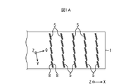
- FIG. 1A is a schematic plan view showing a grain-oriented electrical steel sheet according to an embodiment of the present invention.
- FIG. 1B is a schematic cross-sectional view showing a grain-oriented electrical steel sheet according to an embodiment of the present invention.
- FIG. 2A is a height distribution diagram around the groove of the grain-oriented electrical steel sheet of the invention example.
- FIG. 2B is a three-dimensional representation of FIG. 2A.
- FIG. 3A is a height distribution diagram around the groove of the grain-oriented electrical steel sheet of the comparative example.
- FIG. 3B is a three-dimensional representation of FIG. 3A.
- FIG. 1A is a schematic plan view showing a grain-oriented electrical steel sheet according to an embodiment of the present invention.
- FIG. 1B is a schematic cross-sectional view showing a grain-oriented electrical steel sheet according to an embodiment of the present invention.
- FIG. 2A is a height distribution diagram around the groove of the grain-oriented electrical steel sheet of the invention example.
- FIG. 2B is
- FIG. 4A is a schematic cross-sectional view of the groove of the grain-oriented electrical steel sheet according to the embodiment of the present invention as viewed in a cross-section orthogonal to the groove extending direction Y.
- FIG. 4B is a partially enlarged view of FIG. 4A.
- FIG. 5 is a schematic cross-sectional view of the grooves of the grain-oriented electrical steel sheet of the comparative example as viewed in a cross section orthogonal to the groove extending direction Y.
- FIG. 6 is a schematic cross-sectional view of the protrusions of the grain-oriented electrical steel sheet according to the embodiment of the present invention viewed in a cross section including the groove extending direction Y and the plate thickness direction Z.
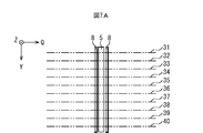
- FIG. 7A is a diagram showing a location where the number of crystal grains is measured.
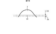
- FIG. 7B is a diagram showing a line segment for measuring the number of crystal grains.
- FIG. 8 is a process diagram illustrating a method for manufacturing a grain-oriented electrical steel sheet according to an embodiment of the present invention.
- FIG. 9A is a schematic diagram showing generation of molten iron by laser irradiation.
- FIG. 9B is a schematic diagram showing the formation of convex portions accompanying solidification of molten iron.
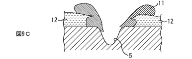
- FIG. 9C is a schematic diagram illustrating generation of molten iron by laser irradiation when a specific substance is applied.
- FIG. 9D is a schematic diagram showing the formation of convex portions accompanying solidification of molten iron when a specific substance is applied.
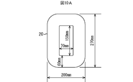
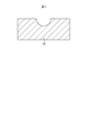
- FIG. 10A is a diagram showing dimensions of the wound core.
- FIG. 10B is a diagram showing dimensions of the wound core.
- FIG. FIG. 2 is a schematic cross-sectional view showing
- FIG. 1A is a plan view showing a grain-oriented electrical steel sheet according to an embodiment of the present invention
- FIG. 1B is a cross-sectional view showing the grain-oriented electrical steel sheet according to an embodiment of the present invention.
- a grain-oriented electrical steel sheet 10 includes a steel sheet 1 having grooves 5 provided on the surface thereof, and a coating 2 formed on the steel sheet surface of the steel sheet 1. It has.
- the film 2 is an insulating film, for example, and may include a glass film.
- the rolling direction of the steel sheet 1 is defined as the X direction
- the extending direction of the grooves 5 is defined as the Y direction
- the thickness direction of the steel sheet 1 is defined as the Z direction
- the direction perpendicular to the Y direction and the Z direction is defined as the Q direction.
- the extending direction Y of the grooves 5 is not limited to the illustrated direction, and may be any direction that intersects the rolling direction X.
- the surface of the steel plate 1 has a plurality of grooves 5 in which the extending direction Y intersects the rolling direction X and the groove depth direction is parallel to the plate thickness direction Z for magnetic domain refinement. Are formed at predetermined intervals along the rolling direction X.
- the groove 5 does not have to be linear when viewed from the plate thickness direction Z, that is, when the groove 5 is viewed in plan, and may have a curved portion, and has an arcuate shape. Also good.
- channel 5 which has a linear shape is illustrated for convenience of explanation.
- FIGS. 3A and 3B show the directional electromagnetic wave outside the scope of the present invention.
- channel of the steel plate contained in a steel plate is shown.
- 2A and 3A show height distributions obtained by measuring the height in the Z direction using a laser-type surface roughness measuring device with respect to the peripheral region of the groove extending in the vertical direction of the drawing.
- 2B and 3B show what is displayed three-dimensionally.
- 2A and 2B show the test No. described later. This is an example corresponding to 1-1, and FIGS. This is a comparative example corresponding to 1-16.
- the convex portion on the surface of the steel plate is formed around the groove along the groove.
- the convex portions are irregularly formed up to a region relatively far from the groove. Such control of the convex portion will be further described below.
- FIG. 4A and FIG. 4B are views of one groove 5 in a cross section (groove short cross section) perpendicular to the groove extending direction Y in the grain-oriented electrical steel sheet of the present embodiment.
- FIG. 4B is a partially enlarged view of FIG. 4A.
- a plurality of convex portions 7 are formed on the surface of the steel plate outside in the groove width direction.
- the convex part 7 is an area
- the convex portion 7 includes not only the roughness that is intentionally controlled, but also an area that is higher than the virtual plane 2a due to unintentional wrinkles or minute surface fluctuations or measurement errors.
- the convex portions 7 those having a height exceeding h / 10 with respect to the virtual plane 2 a and a width of h or more are defined as protrusions T. h will be described later.
- the three convex portions 7 shown on the right side of the groove 5 all correspond to the protrusions T.
- the two convex portions 7 on the side closer to the groove 5 correspond to the protrusion T, but the convex portion 7 farthest from the groove 5 is from the virtual plane 2a. Although it is high but does not exceed h / 10, it does not correspond to the protrusion T.
- FIG. 4A shows a groove 5 that is one of the recesses 6.
- the recess 6 is a region whose height in the Z direction is lower than the virtual plane 2 a, and the groove 5 is also included in the recess 6.
- the recess 6 includes not only the roughness controlled intentionally, but also an area that is lower than the virtual plane 2a due to unintentional wrinkles or minute surface fluctuations or measurement errors.
- the groove 5 is a magnetic domain control recess 6 formed on the surface of the steel plate 1 and can be clearly distinguished from other recesses 6.
- the convex part 7 corresponding to the protrusion T is denoted by the symbol T.
- the protrusion T is formed by discharging molten iron heated by the laser from the groove 5 and depositing and solidifying the molten iron on the surface of the steel plate.
- the protrusion T is made of steel having substantially the same component as the chemical component of the steel plate 1.
- the convex portion 7 is also made of steel having substantially the same component as the chemical component of the steel plate 1.
- the cross-sectional contour surface of the steel sheet in the cross-section shown in FIGS. 4A and 4B is referred in the present embodiment the contour curve QZ 2. It will be described later contour curve QZ 2.
- FIG. 5 is a view of one groove 5 in a cross-section orthogonal to the groove extending direction Y in the grain-oriented electrical steel sheet outside the scope of the present invention. Similar to the grain-oriented electrical steel sheet 10, a plurality of convex portions 7 are formed on the outer surface of the steel sheet in the groove width direction of the groove 5, some of which correspond to the protrusions T. However, in the grain-oriented electrical steel sheet 20, the formation position of the protrusion T is far from the groove 5 as compared with FIGS. 4A and 4B and is random. Further, regarding the size distribution, the one close to the groove 5 is not large, and the second and subsequent n-th protrusions T n (n is an integer of 2 or more) are maximized in the direction away from the groove 5.
- n is an integer of 2 or more
- the width W 2 of the groove 5 second projections T 2 is greater than the width W 1 of the protrusion T 1 of the first one from the groove. That is, the value of W 2 / W 1 is over 1.0.
- the distance L s between the end m of the projections T 1 side of the groove 5 side end T 1s and the groove 5 of the projection T 1 is has become 40 ⁇ m greater.
- FIG. 6 is a view of one protrusion T in the grain-oriented electrical steel sheet 10 as seen in a cross section including the groove extending direction Y and the plate thickness direction Z.
- it referred to as a cross section a roughness curve YZ 3 projections T in cross-section shown in FIG. It will be described later roughness curve YZ 3.
- the grain-oriented electrical steel sheet 10 has the following five configurations (A) to (E) as characteristic configurations for obtaining effects.
- B) The width W 1 of the protrusion T 1 closest to the groove 5 is larger than the widths of the other protrusions.
- the height of the protrusions 7, the width W 1 of the distance L s and projections T 1 of the from the groove 5 of the projection T 1 is within a predetermined range.
- the surface roughness parameters (Ra, RSm) indicating the surface roughness of the region having the largest average height in the Y direction are within a predetermined range. is there.
- the metal structure of each protrusion T substantially matches the metal structure of the steel plate 1.
- a coating similar to the steel plate surface is also formed on the surface of each protrusion T and the surface of the groove 5.
- the metal in the irradiation part melts or evaporates, and a part of the metal becomes droplets or fume and is lost from the irradiation part by being scattered in the space. 6 is formed.
- the protrusion T is formed as a convex portion 7 by attaching the metal removed along with the formation of the groove 5 to the periphery of the groove 5. For this reason, the value of V2 / V1 does not exceed 1.0, and does not greatly decrease from 1.0.
- V2 / V1 can be less than 1 means that the projection T can be made relatively small when the groove 5 having a constant magnetic domain control effect, that is, a constant depth and width is formed.
- the value of V2 / V1 is preferably small, and in this embodiment, it is less than 0.80, preferably less than 0.70, and more preferably. Is less than 0.60.
- the manufacturing method mentioned later it is not difficult to make the value of V2 / V1 less than 0.50, and it can also be made less than 0.40. As a result, the insulation and rust resistance of the grain-oriented electrical steel sheet in which the grooves 5 are formed on the surface of the steel sheet 1 for magnetic domain refinement are improved.
- the protrusion T can contribute to the improvement of the adhesion of the insulating film. When the value of V2 / V1 is 0.10 or less, the protrusion T is too small to obtain sufficient adhesion. Therefore, the value of V2 / V1 is over 0.10.
- the width W 1 of the protrusion T 1 closest to the groove 5 is larger than the widths of the other protrusions in a specific region described later. That is, the width W n of all protrusions T n (n is an integer of 2 or more) appearing after the second in the direction away from the groove width direction of the groove 5 in the specific region is W n / W 1. ⁇ 1.0 is satisfied. In other words, the width W n is smaller than the width W 1 of the protrusion T 1.
- the value of W n / W 1 is preferably less than 0.6, more preferably less than 0.4.
- the maximum value of W n / W 1 is 0.2 or less, when a plurality of directional electromagnetic steel sheets are stacked, a gap is easily generated between the overlapping directional electromagnetic steel sheets. Existence of such a gap leads to an increase in iron loss and noise of a laminated iron core composed of a plurality of grain-oriented electrical steel sheets. Accordingly, the maximum value of W n / W 1 is preferably greater than 0.2.
- the effect of the second and subsequent projection T n is shown in relation to the width of the first projection T 1, it is also the naturally be small narrow projections height, also the height It has been confirmed that a similar relationship holds.
- the end point m is the intersection of the imaginary plane 2a and contour curve QZ 2
- endpoints T 1s is an intersection of the imaginary plane 2a and contour curve QZ 2 at a height of h / 10.
- the value of V2 / V1 is approximately 1.0, and the required width Assuming that the groove 5 having a depth is formed, the total volume of the protrusions T cannot be reduced. Therefore, if the protrusion T is lowered, the width of the protrusion T must be increased. In this embodiment, the value of V2 / V1 can be made smaller than previously thought, and the height and width of the protrusion T can be controlled independently.
- the height of the convex portion 7 from the virtual plane 2a is more than 1 to 10 ⁇ m or less.
- the height of the convex portion 7 is more preferably 6 ⁇ m or less, and further preferably 3 ⁇ m or less.
- the end point m of the projection T 1 side of the groove 5 of the end point T 1s groove 5 side of the projection T 1 closest to the groove 5 The distance L s is preferably more than 0 ⁇ m to 40 ⁇ m, more preferably 0.5 to 25 ⁇ m, and still more preferably 1.0 to 20 ⁇ m.
- the width W 1 of the protrusion T 1 is preferably 40 ⁇ m or less, more preferably 25 ⁇ m or less, and further preferably 15 ⁇ m or less.
- the height of the protrusion T is preferably small.
- the distance L s between the protrusion T 1 and the groove 5 is controlled, and the width of the protrusion T is independently reduced, thereby facilitating the movement of the domain wall and improving the magnetic permeability. 1 has the effect of improving the magnetic characteristics.
- the reason why such an effect can be obtained by reducing the width of the protrusion T is not clear, but the protrusion T is a foreign substance from the steel plate 1 whose crystal orientation is precisely controlled by secondary recrystallization, and is formed on the surface of the steel plate. This is considered to be because there is an adverse effect that hinders the movement of the domain wall due to the presence of the adhesion.
- the distance L s between the protrusions T 1 and the groove 5 is not also why clear that affects the movement of the magnetic wall, that leaves the distance from the groove 5 becomes the presence of foreign matter in the middle of the domain wall, the projections It is considered that the adverse effect is larger than the situation where T 1 is adjacent to the groove 5 and obstructs movement at the end of the domain wall. Therefore, if the total length of the width for a plurality of projections T are the same, the projection T as much as possible it is preferable that the waiting gathered in the vicinity of the groove 5, since second in a direction away from the groove 5 the width of the projection T n It is less than the width of the projection T 1.
- the average roughness Ra of the roughness curve defining the surface of the region is 0.3 to 2.0 ⁇ m or less, preferably 0.5 to 1.7 ⁇ m, more preferably 0.7 to 1.4 ⁇ m.
- the average length RSm of the roughness curve elements is 10 to 150 ⁇ m, preferably 40 to 145 ⁇ m, and more preferably 60 to 140 ⁇ m.
- the fact that the surface roughness parameters (Ra, RSm) are within the above range means that the variation in height in the extending direction Y of the region is small. Therefore, if the surface roughness parameters (Ra, RSm) are within the above ranges, the film breakage due to the stress concentration on the film is avoided, and the height of the maximum height portion of the protrusion T in which insulation is difficult to be secured. Therefore, the insulation is improved. Further, since the fluctuation of the width of the protrusion T is also reduced, the maximum width of the protrusion width that is expected to limit the obstacle effect of domain wall motion is reduced, and the magnetic characteristics are improved.
- a favorable effect can be obtained by controlling the metal structure of the protrusion T.
- most of the protrusions T are formed by attaching the metal removed along with the formation of the groove 5 to the periphery of the groove 5.
- the groove 5 is formed by laser irradiation, the metal removed from the portion of the steel sheet 1 where the groove 5 is to be formed is melted, and if this adheres to the surface of the steel sheet and is rapidly cooled, it is not preferable for the magnetic properties.
- the crystal grains contained in the molten solidified product are fine.
- the crystal orientation of the crystal grains constituting the molten solidified product is likely to deviate from the ⁇ 110 ⁇ ⁇ 001> orientation, and it is highly possible that preferable magnetic properties cannot be obtained. These are also factors that hinder the above-described domain wall movement.
- the metal structure of the protrusion T can be close to the metal structure of the steel sheet 1, the adverse effect as an obstacle to domain wall movement can be reduced.
- the steel plate 1 constituting the grain-oriented electrical steel plate 10 is composed of crystal grains of several tens of mm. Accordingly, considering the size of the crystal grains constituting the protrusion T in the groove extending direction Y, the crystal grains in the protrusion T along the groove 5 formed with a length of several mm to several tens mm are extended. It is also possible to grow to the same size as the current direction. However, the size of the projection T in the Z direction and the Q direction is about several ⁇ m, and it is assumed that crystal grains having a large anisotropy that is as large as several tens of mm in the Y direction are generally isotropic.
- the degree of growth of crystal grains in the protrusion is determined by the average number of crystal grains in the metal structure of the protrusion T when observed in a cross section (groove short cross section) perpendicular to the groove extending direction Y.
- the structure obtained by rapid solidification of the molten iron scattered during the formation of the grooves 5 in the conventional method is formed with very fine crystal grains.
- the number of crystal grains at the bottom of the protrusion T is several tens in the groove short section.
- the protrusion T When the protrusion T is composed of such fine crystal grains, a large amount of crystal grains deviating from the ⁇ 110 ⁇ ⁇ 001> orientation are included.
- the manufacturing method described later if the manufacturing method described later is applied, the protrusion T can be composed of coarse crystal grains, and the average number of crystal grains existing at the bottom of the highest protrusion T in the groove short cross section is obtained. It can be made 10.0 or less. A method for measuring the number of crystal grains will be described later. If the average value of the number of crystal grains exceeds 10.0, many crystal grains deviating from the ⁇ 110 ⁇ ⁇ 001> orientation may be included. Accordingly, the average number of crystal grains is preferably 10.0 or less, more preferably 5.0 or less, and even more preferably 3.0 or less. Most preferably, the protrusion T is composed of a single crystal grain.
- the adverse effect of the protrusion T as a domain wall movement obstacle also depends on the crystal orientation. If the crystal orientation of the protrusion T is the same crystal orientation continuous from the steel plate 1, the obstruction effect of domain wall motion can be made as small as possible. Since the so-called Goss orientation is greatly grown by secondary recrystallization in the steel plate 1, if the grooves 5 and the projections T are formed in the previous process, the projections T are formed from the steel plate 1 side in the secondary recrystallization process. It can be phagocytosed by the grown goth orientation, and the crystal orientation of the protrusion T can be made preferable.
- [About configuration (E)] 4A, FIG. 4B, and FIG. 6 exemplify a state in which no film is present on the steel sheet surface including the surfaces of the grooves 5 and the protrusions T.
- the recesses 6 and the protrusions are illustrated.
- the surface of 7 may be covered with a glass film.
- the glass film is interposed between the insulating film and the steel sheet 1
- adhesion between the steel sheet 1 and the insulating film can be secured, and rust resistance and insulation can be improved.
- the insulating film and the glass film in the groove 5 are lost.
- the insulating film is re-formed after the groove is formed. In this case, since the insulating film is in direct contact with the steel plate on the surface of the groove 5, sufficient adhesion of the insulating film is achieved. May not be secured.
- the groove 5 and the protrusion T are formed before the application of the annealing separator for forming the glass film, and the annealing separator is also applied to the surface of the groove 5 and the surface of the protrusion T.
- the finish annealing it is possible to form a glass film on the inner surface of the groove 5 and the surface of the protrusion T.
- the glass film need not be special. For example, a glass film having a thickness of more than 0 to 5 ⁇ m and an insulating film having a thickness of 1 to 5 ⁇ m can be applied.
- membrane which does not have a glass film and arrange
- these coatings do not have to have the same thickness on the surface of the groove 5, the surface of the protrusion T, and the flat portion (the surface of the steel plate coinciding with a virtual plane described later). Since these films are formed by applying a liquid substance to the surface of the steel sheet, drying, and baking, it is natural that the thickness of the grooves 5 and the protrusions T that are uneven on the surface changes. These thickness changes do not lose the effect of the present invention.
- the distance L s between the groove 5 and the groove 5 and the crystal grain size of the metal structure in the protrusion T have been described with the characteristics of a specific cross section in mind.
- the shape of the protrusion T is not necessarily constant in the extending direction (Y direction) of the groove 5.
- the width W of the protrusion T and the crystal grain size and crystal orientation distribution of the metal structure of the protrusion T also vary greatly depending on the cross section to be observed. Therefore, a method for specifying a quantitative value related to the shape of the steel sheet surface in the present invention will be described below.
- regulated by this invention should be specified by the surface of the steel plate 1, without considering the film
- the surface of the steel sheet 1 is measured by cross-sectional observation, or the steel sheet 1 after peeling the film. It should be measured with.
- the shape of the surface of the steel plate 1 in a state where there is no film rather than specifying the surface of the steel plate 1 by cross-sectional observation and obtaining the necessary measurement values based on the surface. It is suitable to measure three-dimensionally. The method will be described below.
- a sufficiently wide range of Z-direction positions on the steel sheet surface is measured using a laser-type surface roughness measuring instrument including the groove 5 and the protrusion T.
- the extending direction Y of the grooves 5 extends over a range of 1000 ⁇ m, and the Q direction is 400 ⁇ m centered on the grooves (grooves of the grooves).
- a range of 200 ⁇ m on one side is set as a specific region, and the Z-direction position of the surface of the steel sheet 1 is measured at regular intervals within this specific region, and a height distribution of height data is obtained.
- the laser spot diameter is set to 0.40 ⁇ m or less (for example, 0.40 ⁇ m)
- scanning is performed in steps of 0.30 ⁇ m or less (for example, 0.15 ⁇ m) in the Y direction, and 0.30 ⁇ m or less (for example, 0. 15 ⁇ m)
- the measurement accuracy in the Z direction is 0.10 ⁇ m or less (for example, 0.10 ⁇ m)
- the magnification of the objective lens is 50 times.
- the width of the groove 5 which is a recessed area as a height in the Z direction is about 20 ⁇ m, and the area where the metal scattered from this area is deposited on the steel plate surface and becomes the projection T is also a wide area of about 400 ⁇ m in the vicinity of the groove 5 Is considered to be local rather than spreading thinly over the entire surface, and even if there are some irregularities on the surface of the flat portion of the original steel plate 1, the original steel plate surface (in the Z direction) It is considered appropriate to specify the virtual plane 2a regarded as having a height of zero).
- the virtual plane 2a is assumed to be an extended plane for the region where the grooves 5 and the protrusions T are present.
- the virtual plane 2a determined in this way is drawn with a dashed-dotted line. If such a plane is determined, the space volume V1 from which the metal has been removed as the groove 5 is the sum of the product of the step width and the Z direction height at the measurement point where the Z direction height has a negative value. Can be specified.
- the volume V2 in which the molten iron is discharged from the steel sheet surface as the protrusion T to become the convex portion 7 is obtained by calculating the product of the step width and the Z direction height at the measurement point where the Z direction height becomes a positive value. It can be specified by totaling.
- “H” related to the height of the convex portion 7 is specified as a height where the above-mentioned surface shape data is arranged in descending order of the height in the Z direction and the rank becomes 0.02% of the whole. For example, in the case of data of 10 million points, the height of the 2000th measurement point is h.
- the actual height of the convex portion 7 may be various heights from 0 to various heights.
- the size of the convex portion 7 is represented by h.
- the height of h is considered to be a value corresponding to the height of the relatively high convex portion 7 among the many convex portions 7 present, but the characteristics to be noticed, that is, insulation and rust resistance Considering that magnetic characteristics and the like are strongly influenced by the relatively high convex portion 7, such an evaluation is considered appropriate.
- curves representing the steel sheet surface in the Y-direction vertical section (groove short section) and the Q-direction vertical section (groove longitudinal section) are used. In the following, first, how to obtain these curves will be described.
- a series of data having the same position in the Y direction that is, a cross section curve QZ 1 representing a change in height in the height data at a specific QZ cross section is obtained.
- a contour curve QZ 2 Figure 4A
- a series of data having the same position in the Q direction that is, a cross section curve YZ 1 representing a change in height in the height data in a specific YZ cross section is obtained. Furthermore, for each section curve YZ 1 in a particular direction Q position determines the average Za height. Of sectional curve YZ 1, profile curve average Za is maximum is contour curve YZ 2. Contour curve YZ 2, the average height of the extending direction Y corresponds to the contour curve of the highest region in the height distribution.
- the position in the Q direction where the contour curve YZ 2 is obtained coincides with the position where the height in the Z direction is the highest in the contour curve QZ 2 . And this position is typically a position of the top portion of the projection T 1 of the later.
- Cut-off values ⁇ s and ⁇ c are determined by the type of laser surface roughness measuring instrument and the objective lens.
- a point at which the contour curve QZ 2 first intersects the virtual plane 2 a in the center in the Q direction, that is, in the direction away from the center of the groove 5 is a groove end point m.
- the protrusion T is defined in a region farther from the groove than the groove end point m.
- the reason for specifying the protrusion T with such a rule is that the surface of the steel sheet 1 has unevenness different from the unevenness that should be controlled in order to obtain the effects of the present invention.
- the irregularities that should be excluded may be minute irregularities (roughness) that appear during rolling, or numerical fluctuations due to measurement errors. Since these are very fine according to the current industrial manufacturing technology and measurement accuracy, the contour curve QZ 2 is obtained by averaging the cross-sectional curve QZ 1 as raw data with respect to the Y direction position as described above. Although a considerable part is considered to disappear due to the processing to be obtained, the unevenness having a relatively small height and width as compared with the height h as described above is excluded from the evaluation target.
- the projections are numbered in order from the side closer to the groove.
- position T ns side endpoint closer to the groove of the projection T n the position on the far side of the end point from the groove as the T ne, T ns and T distance projections T n between ne which is the width W n.
- Each of the end points T ns and T ne is an intersection of the virtual surface and the contour curve QZ 2 at a height of h / 10.
- the distance between the groove end point m and T 1s is L s .
- the average height of the Y direction determining an average length RSm of the average roughness Ra and roughness curve element of highest elevation T.
- the average roughness Ra and the average length RSm of the roughness curve element are determined according to Japanese Industrial Standard JIS B 0601 (2013).
- the average number of crystal grains forming the protrusions T is determined from a cross section perpendicular to the groove extending direction Y (groove short cross section, QZ plane).
- the metal structure of the groove short cross section is observed at 10 observation points 31 to 40 in the Y direction, and exists at the bottom of the highest protrusion T in each of the observation points 31 to 40.
- the number of crystal grains to be obtained is obtained. That is, as shown in FIG. 7B, the number of crystal grains present on a line segment 41 having a Z-direction height of the projection T of h / 10 in the short cross section of the groove is obtained. Then, the average value of the number of crystal grains for each of the observation locations 31 to 40 is calculated.
- the means for observing the metal structure of the steel sheet 1 can be a known means. However, since the size of the protrusion in the short cross section of the groove is several ⁇ m, it is preferable to observe with a scanning electron microscope (SEM). .
- the crystal orientation in the projection T is determined by observing the cross section of the metal structure to obtain a contour curve YZ 2. It should be noted that the crystal orientation is obtained by limiting only to the region corresponding to the protrusion T in the cross-sectional structure, that is, the region where the height in the Z direction is h / 10. For the crystal orientation, the area ratio of the ⁇ 110 ⁇ ⁇ 001> orientation in the region is determined by the backscattered electron diffraction pattern (EBSD) method.
- EBSD backscattered electron diffraction pattern
- the measurement conditions for EBSD are as follows.
- the area ratio of the region having the ⁇ 110 ⁇ ⁇ 001> ( ⁇ 10 °) orientation is defined as the area ratio in the present invention.
- the area ratio is preferably 65% or more from the viewpoint that the magnetic properties can be improved. That is, it is preferable that the area ratio of the ⁇ 100 ⁇ ⁇ 001> orientation is 65% or more with respect to the crystal orientation of the metal structure of the protrusion T in the region having the highest average height in the groove extending direction Y in the height distribution.
- the specified value of the protrusion T is measured near the center of the extending direction. This is because at the extended end of the groove 5, the depth of the groove 5 becomes shallower and the change in the shape of the projection T becomes larger as it approaches the extended end due to a change in the laser irradiation angle.
- the groove 5 does not have to be linear, in the measurement of the surface height Z by the three-dimensional roughness meter, the Y direction and the direction of the length of 1000 ⁇ m in the measurement region are exactly the same. It is also possible not to. However, even if the groove 5 is formed in a curved shape, the groove 5 manufactured in the practical range as an industrial product can be substantially straight if the distance is about 1000 ⁇ m. To define the features.
- the variation of the plurality of grooves 5 is within the range of the manufacturing variation of industrial products, and it is not necessary to give special consideration to judgment based on abnormal values.
- a value averaged over a length of 1 mm in the extending direction is used, and a representative value is obtained to the extent that there is no problem with respect to the variation for each groove 5.
- the protrusion 5 defined in the present invention is the surface shape of the steel plate 1. That is, it is not the shape from the top of the film of the grain-oriented electrical steel sheet having the film. Even if a film is formed on the surface of the steel plate 1, this can be measured visually by observing the cross section. However, in order to quantify various values, it is easy to operate by measuring the surface shape using the three-dimensional roughness measuring apparatus as described above. In this case, the surface of the steel sheet 1 without a film is measured. It is necessary to measure. If the groove 5 and the protrusion T are formed before the film is formed, this may be measured immediately after the formation or before the film is formed. Moreover, if it measures after film formation, it can measure by removing the glass film and insulating film of a grain-oriented electrical steel sheet, for example with the following method.
- a grain-oriented electrical steel sheet having a glass coating or an insulating coating is immersed in a sodium hydroxide aqueous solution of NaOH: 10% by mass + H 2 O: 90% by mass at 80 ° C. for 15 minutes. Then, it is immersed in a sulfuric acid aqueous solution of H 2 SO 4 : 10% by mass + H 2 O: 90% by mass at 80 ° C. for 3 minutes. Thereafter, the substrate is dipped and washed with a nitric acid aqueous solution of HNO 3 : 10% by mass + H 2 O: 90% by mass for 1 minute at room temperature. Finally, dry with a warm air blower for 1 minute.
- the shape and roughness of the groove 5 of the steel sheet 1 are the same as before the glass film or the insulating film is formed. ing. Furthermore, the groove 5 formed in the middle of the steel plate manufacturing process changes its shape greatly when a large deformation such as cold rolling is performed thereafter, but it passes through these processes if annealing or film formation is performed. Even so, it has been confirmed that the change in shape is small.
- the provision relating to the protrusion T is applied to the final product, and when a film is formed on the surface of the final product, it is applied to the peeled steel plate 1.
- the steel sheet 1 is, for example, in mass%, Si: 0.8 to 7%, C: more than 0 to 0.085%, acid-soluble Al: 0 to 0.065%, N: 0 to 0.00. 012%, Mn: 0 to 1%, Cr: 0 to 0.3%, Cu: 0 to 0.4%, P: 0 to 0.5%, Sn: 0 to 0.3%, Sb: 0 to 0.3%, Ni: 0 to 1%, S: 0 to 0.015%, Se: 0 to 0.015%, with the balance being Fe and impurities.
- the chemical component of the steel plate 1 is a preferable chemical component for controlling the Goss texture in which the crystal orientation is accumulated in the ⁇ 110 ⁇ ⁇ 001> orientation.
- Si and C are essential elements
- acid-soluble Al, N, Mn, Cr, Cu, P, Sn, Sb, Ni, S, and Se are selective elements. Since the above-mentioned selective element may be contained according to the purpose, it is not necessary to limit the lower limit value, and the lower limit value may be 0%. Further, the selective element is not limited to the above elements, and even if a known element having a known effect in the grain-oriented electrical steel sheet is contained in a known range, the effect of the present embodiment is not impaired.
- the essential elements of the steel plate 1 and the remainder of the selective elements are composed of Fe and impurities.
- An impurity means an element inevitably mixed from ore, scrap, or a production environment as a raw material when the steel sheet 1 is industrially manufactured.
- grain oriented electrical steel sheets generally undergo purification annealing during secondary recrystallization.
- the inhibitor forming elements are discharged out of the system.
- the decrease in the concentration is remarkable, and it becomes 50 ppm or less.
- N and S are each 9 ppm or less, and further 6 ppm or less. If sufficient purification annealing is performed, it reaches a level that cannot be detected by general analysis (1 ppm or less).
- the chemical composition of the steel plate 1 may be measured by a general steel analysis method.
- the chemical composition of the steel sheet 1 may be measured using ICP-AES (Inductively Coupled Plasma-Atomic Emission Spectrometry). Specifically, it can be specified by measuring a 35 mm square test piece of the steel sheet 1 after removal of the film, using an ICPS-8100 manufactured by Shimadzu Corporation (measurement device) under conditions based on a calibration curve prepared in advance.
- C and S may be measured using a combustion-infrared absorption method
- N may be measured using an inert gas melting-thermal conductivity method.
- the rust resistance and insulation properties as well as the magnetic properties of the grain-oriented electrical steel sheet in which the grooves 5 and the protrusions T are formed on the steel sheet surface for magnetic domain refinement are greatly improved. It is possible.
- FIG. 8 is a flowchart showing a method for manufacturing a grain-oriented electrical steel sheet according to an embodiment of the present invention.
- the present manufacturing method includes a casting step S01, a hot rolling step S02, an annealing step S03, a cold rolling step S04, a decarburizing annealing step S05, an annealing separator coating step S06, a finish annealing step S07, Insulating film forming step S08 and laser irradiation step S99 are included.
- this manufacturing method is a groove formation (projection formation) step by laser irradiation, but this step can be performed at a plurality of timings of the steel plate manufacturing process over many steps. For this reason, in the following description, the manufacturing method of a general grain-oriented electrical steel sheet will be described first, and then the laser irradiation step S99 for forming grooves and protrusions will be described.
- the casting step S01 for example, in mass%, Si: 0.8 to 7%, C: more than 0 to 0.085%, acid-soluble Al: 0 to 0.065%, N: 0 to 0.012%, Mn: 0 to 1%, Cr: 0 to 0.3%, Cu: 0 to 0.4%, P: 0 to 0.5%, Sn: 0 to 0.3%, Sb: 0 to 0.3 , Ni: 0 to 1%, S: 0 to 0.015%, Se: 0 to 0.015%, and the balance is supplied to the continuous casting machine having a chemical component composed of Fe and impurities.
- the slab is continuously produced.
- the slab obtained in the casting step S01 is heated to a predetermined temperature (for example, 1150 to 1400 ° C.), and then hot rolling is performed. Thereby, for example, a hot-rolled steel sheet having a thickness of 1.8 to 3.5 mm is obtained.
- a predetermined temperature for example, 1150 to 1400 ° C.
- the hot-rolled steel sheet obtained in the hot rolling step S02 is annealed under a predetermined temperature condition (for example, a condition of heating at 750 to 1200 ° C. for 30 seconds to 10 minutes).
- a predetermined temperature condition for example, a condition of heating at 750 to 1200 ° C. for 30 seconds to 10 minutes.
- cold rolling process S04 after the hot-rolled steel sheet that has been annealed in the annealing process S03 is pickled, cold rolling is performed. Thereby, for example, a cold-rolled steel sheet having a thickness of 0.15 to 0.35 mm is obtained.
- the cold-rolled steel sheet obtained from the cold rolling step S04 is subjected to heat treatment (ie, decarburization annealing) under predetermined conditions (for example, heating at 700 to 900 ° C. for 1 to 3 minutes).
- heat treatment ie, decarburization annealing
- predetermined conditions for example, heating at 700 to 900 ° C. for 1 to 3 minutes.
- carbon will be reduced to a predetermined amount or less, and a primary recrystallized structure will be formed.
- an oxide layer containing silica (SiO 2 ) as a main component is formed on the surface of the cold rolled steel sheet.
- nitridation annealing is performed subsequent to the decarburization annealing step S05.
- nitridation annealing is also included in the decarburization annealing step S05.
- an annealing separator containing magnesia (MgO) as a main component is applied to the surface of the cold rolled steel sheet (the surface of the oxide layer).
- the finish annealing step S07 the cold-rolled steel sheet coated with the annealing separator is subjected to heat treatment (ie, finish annealing treatment) under a predetermined condition (for example, heating at 1100 to 1300 ° C. for 20 to 24 hours). Is done.
- finish annealing treatment ie, finish annealing treatment
- secondary recrystallization occurs in the cold-rolled steel sheet, and the cold-rolled steel sheet is purified.
- a cold-rolled steel sheet having the chemical composition of the steel sheet 1 described above and whose crystal orientation is controlled so that the easy axis of crystal grains coincides with the rolling direction X is obtained.
- the oxide layer containing silica as a main component reacts with an annealing separator containing magnesia as a main component, and on the surface of the cold-rolled steel sheet, for example, A glass film containing a composite oxide such as forsterite (Mg 2 SiO 4 ), spinel (MgAl 2 O 4 ), or cordierite (Mg 2 Al 4 Si 5 O 16 ) is formed.
- the finish annealing step S07 the finish annealing process is performed in a state where the cold-rolled steel sheet is wound in a coil shape.
- an insulating coating liquid containing, for example, colloidal silica and phosphate is applied from above the glass film.
- a baking heat treatment is performed under a predetermined temperature condition (for example, 840 to 920 ° C.).
- the laser irradiation step S99 can be carried out at any timing after the casting step S01. However, the groove 5 and the protrusion T of about several hundred ⁇ m at most as the change in the surface shape are subsequently subjected to hot rolling, pickling, When cold rolling is carried out, it almost disappears. For this reason, it should be implemented at least after the cold rolling step S04. First, features that appear depending on the execution timing of the laser irradiation step S99 will be described.
- the rolling oil present on the surface of the steel plate as it is rolled effectively acts on the shape control of the surface of the steel plate, and the groove 5
- An oxide layer containing silica (SiO 2 ) generated during the decarburization annealing process as a main component is also formed on the surface of the protrusion T. This is advantageous for forming a good glass film in the final product.
- the laser irradiation step S99 can be performed in the middle of the decarburization annealing step S05. If laser irradiation is performed before the nitridation annealing, the surface layer region of the groove 5 and the region of the protrusion T also have a structure in which inhibitor control is performed by nitridation. Therefore, the crystal orientation of these regions is also changed by subsequent secondary recrystallization. It is expected to be preferably controlled. However, in general, nitriding annealing is performed after decarburization annealing without lowering the steel plate temperature so as to avoid an increase in energy cost. In order to perform laser irradiation in the middle of this, it is necessary to cool the steel sheet once and reheat it for nitriding after laser irradiation. Therefore, this point should be taken into consideration when performing at this timing. .
- the laser irradiation step S99 is performed between the decarburization annealing step S05 and the annealing separating agent application step S06, a glass film can be formed on the surfaces of the grooves 5 and the protrusions T.
- the oxide layer mainly composed of silica formed in the decarburization annealing step S05 disappears on the surface of the groove 5 and the surface of the protrusion T, it cannot be said that the state of the glass film is preferable.
- the surface layer region and the protrusion T region of the groove 5 are not in a preferable state of the inhibitor, and the Goss orientation as the preferred crystal orientation from this region is not.
- the liquid annealing separation agent effectively acts on the shape control of the steel sheet surface. Irradiation should be performed. Although the annealing separator applied to the surface of the groove 5 is dissipated immediately after laser irradiation, if the annealing separator is in a liquid state, the surface of the groove 5 is again covered with the annealing separator. However, it should be noted that the molten iron that has been solidified by riding on the annealing separator has a considerable influence on the subsequent glass film formation and may cause local film defects.
- the laser irradiation step S99 can also be performed in the insulating film forming step S08.
- an insulating coating solution is applied to the steel sheet and a baking heat treatment is performed.
- the insulating coating solution can be used to control the surface state of the steel sheet of the present invention.
- laser irradiation is performed before baking heat treatment, and then baking heat treatment is performed.
- a glass film does not exist on the surface of the groove 5 and the protrusion T, an insulating film is formed for the time being. There is an advantage that it is not necessary to re-form the insulating film which is necessary when the groove 5 and the protrusion T are formed in the final product.
- the insulating film does not exist on the surfaces of the grooves 5 and the protrusions T, and as described above, the insulating film is formed to ensure rust resistance and insulation. Since reformation is required, there is no merit to carry out in this process.
- a liquid annealing separator is applied between the annealing separator coating process S06 and the finish annealing process S07.
- the insulating coating liquid is used as a coating material in the middle of the insulating film forming step S08, it is advantageous because it is not necessary to remove the coating material.
- the laser irradiation step S99 is particularly preferably performed between the cold rolling step S04 and the decarburization annealing step S05 as shown in FIG.
- the steel sheet surface after cold rolling is unavoidably rolled oil. This is also very convenient.
- the laser irradiation step S99 will be described.
- the laser is irradiated toward the surface of the steel sheet, and the grooves 5 are formed on the surface of the steel sheet.
- a protrusion T is formed with the formation of the groove 5.
- the said specific substance is the rolling oil used by cold rolling, for example.
- the laser control conditions do not have to be special, and known conditions are employed.
- a laser emitted from a laser light source is transmitted to a laser irradiation device via an optical fiber, and the laser is irradiated toward the surface of the steel sheet by a polygon mirror and its rotation driving device, and the laser is cold-rolled. It is formed by scanning substantially parallel to the plate width direction of the steel plate.
- an assist gas such as air or an inert gas may be blown onto the portion of the steel plate irradiated with the laser.
- the assist gas plays a role of removing components scattered or evaporated from the steel sheet by laser irradiation.
- a plurality of grooves 5 intersecting the rolling direction can be formed at predetermined intervals along the rolling direction by synchronously controlling the rotation speed of the polygon mirror and the conveying speed of the steel sheet in the rolling direction.
- a fiber laser can be used as the laser light source.
- a high-power laser generally used for industrial use such as a YAG laser, a semiconductor laser, or a CO 2 laser may be used as the laser light source.
- a pulse laser or a continuous wave laser may be used as a laser light source.
- the laser it is preferable to use a single mode laser which has a high light collecting property and is suitable for forming the groove 5.
- Laser irradiation conditions include, for example, a laser output of 200 to 2000 W, a focused spot diameter in the laser rolling direction (a diameter including 86% of the laser output) of 10 to 1000 ⁇ m, and a focused spot in the laser plate width direction. It is preferable to set the diameter to 10 to 1000 ⁇ m, the laser scanning speed to 5 to 100 m / s, and the laser scanning pitch (interval) to 2 to 10 mm. These laser irradiation conditions may be appropriately adjusted within a known range so that a desired groove depth can be obtained. For example, in order to obtain a deep groove depth, the laser scanning speed may be set slower and the laser output may be set higher.
- the coating substance is preferably a liquid substance such as fats and oils, water, alcohol, colloid, emulsion, an annealing separator used in the production of a grain-oriented electrical steel sheet, and an insulating coating solution.
- oils and fats used as rolling oil and rust preventive oil are easy to handle and more preferable.
- Rolling oil is particularly preferred because it does not need to be reapplied after cold rolling.
- the applied substance satisfies the following two conditions.
- the material has a viscosity within a specific range and is liquid and can be deformed instantaneously even with a relatively small force.
- the thickness of the liquid film on the surface of the steel sheet after application is within a specific range, and while suppressing the spread of molten iron, when a part of the molten iron rides on the liquid film, It is a substance that suppresses the welding of molten iron to the steel sheet by interposing it with the steel sheet.
- the grain-oriented electrical steel sheet according to the embodiment of the present invention can be manufactured.
- the steel sheet 1 contained in the grain-oriented electrical steel sheet has, as chemical components, mass%, Si: 0.8 to 7%, C: more than 0 to 0.085%, acid-soluble Al: 0 to 0.065%, N: 0 to 0.012%, Mn: 0 to 1%, Cr: 0 to 0.3%, Cu: 0 to 0.4%, P: 0 to 0.5%, Sn: 0 to 0.3 %, Sb: 0 to 0.3%, Ni: 0 to 1%, S: 0 to 0.015%, Se: 0 to 0.015%, with the balance being Fe and impurities.
- the molten iron 11 is specified when the molten iron 11 is pushed out around the groove 5.
- the substance 12 is pushed out of the groove 5 and scattering is suppressed.
- the molten iron 11 is prevented from being scattered far from the groove 5 by the film of the specific substance 12.
- a part 13 of the molten iron 11 rides on the coating film of the specific substance 12.
- the molten iron 13 riding on the coating film is solidified and peeled off on the coating film of the specific substance 12 and does not remain as a welded material on the steel sheet surface.
- the total amount of the welded material decreases.
- the welded material scattered to a point far from the groove is solidified and peeled off on the coating film of the specific substance 12 and does not remain as a welded material on the steel plate surface, only the protrusion close to the groove (protrusion T 1 ). so that the width of the projections (projecting T 2 later) away from the groove than the projection T 1 is smaller than the width of the projection T 1.
- the coating material may be defined in contact with hot molten iron, but this is not practical.
- invention is prescribed
- the viscosity of the coating material is preferably 100 mm 2 / s or less.
- the effect of the present invention is considered to be obtained if any substance that has viscosity and is deformed by the force received from molten iron is applied, so the lower limit is not particularly limited, but if the viscosity is too high, such as application In addition to being difficult to handle, it prevents proper spread of the melt around the groove, deposits only in the very vicinity of the groove 5 and increases the height h of the convex portion, and the desired V2 / V1. Cannot be obtained.
- the viscosity is preferably 10 to 70 mm 2 / s or less, and more preferably 40 to 60 mm 2 / s.
- the viscosity can be controlled by changing the coating material, but it can also be controlled by changing the temperature and concentration, for example.
- the temperature of the coating substance is preferably 10 to 100 ° C.
- the temperature is preferably 15 to 60 ° C, more preferably 20 to 50 ° C.
- an appropriate temperature range should be determined in consideration of temperature management and ease of handling in the manufacturing process.
- the coating substance is oil or fat or an emulsion of oil or fat, the above temperature range roughly matches the preferred range for viscosity.
- the concentration when applying a colloidal solution such as an oil or fat emulsion or an annealing separator or an insulating coating solution generally used in the manufacturing process of grain-oriented electrical steel sheet is the sum of water and fat if the emulsion is an oil or fat.
- the volume concentration of fats and oils is 50-70%
- the annealing separator is 5-80% magnesia with water and magnesia
- the insulating coating solution is water, aluminum phosphate, colloidal silica, and chromic acid.
- the viscosity can be controlled to preferably obtain the protrusion control effect of the present invention.
- the appropriate concentration range is the same as the temperature in consideration of temperature adjustment and ease of handling in the manufacturing process as well as the adjustment of the viscosity for obtaining the invention effect.
- the thickness of the coating material is preferably more than 0 to 50 ⁇ m, more preferably 0.01 to 25 ⁇ m, and still more preferably 0.1 to 1 ⁇ m.
- the boiling point of the coating material is preferably 100 ° C. or higher. If the boiling point is too low, the substance evaporates from the periphery of the groove, which becomes instantaneously high temperature during laser irradiation, and the effect of the present invention is lost. Even if it does not evaporate completely, the thickness of the coating material becomes thin, the effect of keeping the coating material around the groove is reduced, the distance L s and the protrusion width W become excessively large, and the film is too thin. Further, it is not possible to suppress the welding of the molten iron on the coating film to the mother steel plate, and the desired V2 / V1 cannot be obtained.
- the boiling point is more preferably 130 ° C or higher, and further preferably 150 ° C or higher. In the case of a mixed substance, the boiling point of the solvent should be controlled.
- the manufacturing conditions of the grain-oriented electrical steel sheet to be used are as follows. In mass%, Si: 3.0%, C: 0.08%, acid-soluble Al: 0.05%, N: 0.01%, Mn: 0.12%, Cr: 0.05%, Cu: 0.04%, P: 0.01%, Sn: 0.02%, Sb: 0.01%, Ni: 0.005%, S: 0.007%, Se: 0.001% And hot rolling is implemented with respect to the slab which has a chemical component which the remainder consists of Fe and an impurity, and a 2.3 mm-thick hot-rolled steel plate is obtained.
- the above hot-rolled steel sheet is annealed at 1000 ° C. for 1 minute. Thereafter, pickling and cold rolling are performed to obtain a cold-rolled steel sheet having a thickness of 0.23 mm.
- the cold-rolled steel sheet is decarburized and annealed at 800 ° C. for 2 minutes, and an annealing separator containing magnesia (MgO) as a main component is applied to the surface. If necessary, known nitriding annealing is performed.
- MgO magnesia
- An insulating coating solution containing colloidal silica and phosphate is applied to the above steel plate, and heat treatment is performed at 850 ° C. for 1 minute. Finally, grooves and protrusions are formed, and a glass film and insulation are further formed on the surface. A grain-oriented electrical steel sheet having a coating is obtained.
- the laser irradiation conditions are: laser output: 200 W, focused spot diameter (86% diameter) in the laser rolling direction: 100 ⁇ m, focused spot diameter (86% diameter) in the laser plate width direction: 4000 ⁇ m, laser scanning speed: 16 m / s, laser scanning pitch: 4 mm.
- the above-mentioned grain-oriented electrical steel sheet finally obtained is usually a normal one containing Si: 3.0%, except for the shape of protrusions that change according to the application conditions of the specific material on the steel sheet surface during laser irradiation. It is a grain-oriented electrical steel sheet.
- the application conditions of the specific substance and the execution timing including laser irradiation, which are the points of the present invention, will be described in each experimental example.
- the depth of the groove of the steel plate to be evaluated is 25-30 ⁇ m or less, the width of the groove is 30-40 ⁇ m, and it is within the range of the groove shape variation when the laser irradiation conditions are constant, and is a well-known range. is not.
- a laser type surface roughness measuring instrument (VK-9700 manufactured by Keyence Corporation) is used for measurement of three-dimensional roughness and measurement of surface roughness parameters (Ra, RSm).
- the measured value for the protrusion is an average value of the values measured for the protrusions on both sides of the groove.
- Insulation is evaluated by the interlayer current measured by the method described in JIS C 2550-4.
- Magnetic properties are evaluated by a single plate of W 60 mm ⁇ L 300 mm according to the H coil method described in JIS C 2556.
- each grain-oriented electrical steel sheet is laminated, and a wound core 20 having the dimensions (mm) shown in FIGS. 10A and 10B is produced.
- the wound core 20 is fastened with a band 21.
- the wound core 20 a measurement using the excitation current method described in JIS C 2550-1, performed at a frequency 50 Hz, magnetic flux density 1.7T conditions, to measure the iron loss value W A of the winding core .
- a sample having a width of 100 mm and a length of 500 mm consisting only of the plane portion of the grain-oriented electrical steel sheet used for the wound iron core was sampled, and an electrical steel sheet using the H coil method described in JIS C 2556 was used for this sample.
- the measurement by the plate magnetic property test carried out at a frequency 50 Hz, magnetic flux density 1.7T conditions, to measure the iron loss value W B of the steel sheet veneer.
- the building factor (BF) is obtained by dividing the iron loss value W A by the iron loss value W B.
- Test No. In 1-22 the insulating coating solution applied in the insulating coating forming step S08 was irradiated with laser using the specific material, and then the insulating coating was baked. Test No. In 1-23, after the insulating film forming step S08, laser irradiation was performed on the film. Test No. In 1-24, the process up to the formation of the insulating film was performed without forming the groove.
- Test No. 1-2 to No. In No. 1-15 after cold rolling, the rolling oil on the surface of the steel sheet was once removed by electrolytic degreasing, and then a predetermined coating material was applied under predetermined conditions. Die roll SZ-48H is used as rolling oil in cold rolling before coating. In 1-1, laser irradiation was performed with the rolling oil adhering to the surface immediately after rolling. Test No. 1-2 to No. In 1-15, the rolling oil was once degreased after the cold rolling step S04, and then the coating substance was re-coated. Test No. Daphne Roll Oil, Daphne High Ten Oil, Daphne Marg Plus and Daphne Oil Coat used in 1-4 etc. are manufactured by Idemitsu Kosan Co., Ltd.
- a sectional view of a steel plate 51 of 1-23 is shown. Further, in the invention example in which the laser irradiation step S99 is performed before the decarburization annealing step S05, at least some secondary recrystallization occurs in the finish annealing, so that the crystal grain size and crystal orientation including the protrusions are controlled, and the magnetic The characteristics were also good. Test No. In No. 1-24, since no groove was formed, the iron loss could not be reduced sufficiently.
- the steel plate of the second experimental example is manufactured by a process that does not include nitriding annealing. Details are shown in Tables 4-6.
- Test No. 2-1 In 2-16, coating of the coating material and laser irradiation were performed between the cold rolling step S04 and the decarburizing annealing step S05.
- the coating substance and coating thickness are made constant, and the viscosity is changed by the concentration and temperature in the coating state.
- the coating material was all die roll SZ-48H (manufactured by Daido Chemical Co., Ltd.), and the case of as-rolled and the case of recoating after degreasing were evaluated.
- the steel plate of the third experimental example is manufactured by a process including nitriding annealing. Details are shown in Tables 7-9.
- Test No. 3-1 In 3-16, coating of the coating material and laser irradiation were performed between the cold rolling step S04 and the decarburizing annealing step S05. In this example, the coating substance and viscosity are made constant, and the influence of coating thickness is confirmed.
- the coating material was all die roll SZ-48H (manufactured by Daido Chemical Co., Ltd.), and the case of as-rolled and the case of recoating after degreasing were evaluated.
- the change of the invention effect accompanying the change of the coating thickness can be confirmed, and it can be confirmed that the coating thickness has a particularly preferable range.
- the coating thickness is thin, there is a tendency that the protrusion can be made small, but the scattering of the molten iron cannot be sufficiently suppressed, and the protrusion is formed at a position away from the groove.
- molten iron cannot run on the film, V2 / V1 deteriorates, and is concentrated and deposited in the vicinity of the groove. In such a state, the variation (Ra, RSm) of the protrusion form becomes large, a protrusion that is difficult to cause secondary recrystallization locally occurs, and the magnetic characteristics tend to decrease.
- the present invention can be used, for example, in the manufacturing and use industries of grain-oriented electrical steel sheets for transformer iron cores.
Landscapes
- Chemical & Material Sciences (AREA)
- Engineering & Computer Science (AREA)
- Mechanical Engineering (AREA)
- Organic Chemistry (AREA)
- Metallurgy (AREA)
- Materials Engineering (AREA)
- Physics & Mathematics (AREA)
- Thermal Sciences (AREA)
- Crystallography & Structural Chemistry (AREA)
- Manufacturing & Machinery (AREA)
- Electromagnetism (AREA)
- Power Engineering (AREA)
- Dispersion Chemistry (AREA)
- Optics & Photonics (AREA)
- Plasma & Fusion (AREA)
- Manufacturing Of Steel Electrode Plates (AREA)
- Soft Magnetic Materials (AREA)
Abstract
Description
延在方向が圧延方向と交差し、且つ深さ方向が板厚方向と平行な溝が形成された鋼板表面を有する鋼板を備え、
前記鋼板の表面の前記溝の両側に前記溝と平行に連なる溶融凝固物が存在し、
前記溝を含む特定領域内の前記鋼板表面を一定の間隔で測定した高さデータの高さ分布において最大度数となる高さを仮想平面とし、前記仮想平面より凹んだ凹部の空間体積をV1とし、前記仮想平面よりも突出した凸部の体積をV2としたとき、V2/V1の値が0.10超0.80未満であり、
前記特定領域内に複数の突起が形成されており、前記複数の突起のうちで、前記溝に最も近い突起の幅が他の突起の幅よりも大きく、
前記高さ分布において前記延在方向の平均高さが最も高い領域を延在方向及び板厚方向を含む溝長手断面で視た場合に、
当該領域の表面を成す粗さ曲線の平均粗さRaが、0.30~2.00μmであり、
当該領域の表面を成す粗さ曲線要素の平均長さRSmが、10~150μmであることを特徴とする方向性電磁鋼板。
前記の高さデータにおいて0.02%番目となる高さが、1超~10μmであることを特徴とする(1)に記載の方向性電磁鋼板。
前記溝周辺の鋼板表面形状を、溝延在方向と垂直な溝短手断面で視た場合に、
前記凸部のうち、前記溝に最も近い突起の端部T1sと前記溝の端部mとの距離Lsが、0超~40μmであることを特徴とする(1)又は(2)に記載の方向性電磁鋼板。
前記複数の突起のうちで、前記溝に最も近い突起の幅W1が、40μm以下であることを特徴とする(1)~(3)のいずれかに記載の方向性電磁鋼板。
前記複数の突起のうちで、前記溝に最も近い突起の幅をW1、第n番目(nは2以上の整数)に近い突起の幅をWnと表したとき、Wn/W1の値が0.20超1.00未満であることを特徴とする(1)~(4)のいずれかに記載の方向性電磁鋼板。
前記溝延在方向に垂直な断面において最も高い突起の底に存在する結晶粒の数が平均で10.0個以下であることを特徴とする(1)~(5)のいずれか1項に記載の方向性電磁鋼板。
前記高さ分布において前記延在方向の平均高さが最も高い領域内の突起の金属組織の結晶方位について、{100}<001>方位の面積率が65%以上であることを特徴とする(1)~(6)のいずれかに記載の方向性電磁鋼板。
前記凸部表面及び溝表面を含む前記鋼板表面上に、グラス皮膜を備えていることを特徴とする(1)~(7)のいずれかに記載の方向性電磁鋼板。
(A)仮想平面2aを基準として、凹部6の空間体積をV1とし、凸部7の体積をV2としたときに、V2/V1の値が所定の範囲内にある。
(B)溝5に最も近い突起T1の幅W1が他の突起の幅よりも大きい。好ましくは、凸部7の高さ、突起T1の溝5からの距離Ls及び突起T1の幅W1が所定範囲内にある。
(C)溝延在方向及び板厚方向に平行な溝長手断面において、Y方向の平均高さが最も大きい領域の表面粗さを示す表面粗さパラメータ(Ra、RSm)の値が所定範囲内である。
(D)好ましくは、各突起Tの金属組織が、鋼板1の金属組織と実質的に一致している。
(E)好ましくは、各突起Tの表面及び溝5の表面にも、鋼板表面と同様の皮膜が形成されている。
本実施形態では、仮想平面2aより凹んだ凹部6の総空間体積をV1とし、仮想平面2aよりも突出した凸部7の総体積をV2としたとき、V2/V1の値が0.10超0.80未満である。
本実施形態では、後述の特定領域内で、溝5に最も近い突起T1の幅W1が他の突起の幅よりも大きい。すなわち、特定領域内で、溝5の溝幅方向の外側に離れる方向において、2番目以降に現れるすべての突起Tn(nは2以上の整数)について、その幅WnがWn/W1<1.0を満たす。つまり、幅Wnは突起T1の幅W1より小さい。Wn/W1の値は、好ましくは0.6未満であり、より好ましくは0.4未満である。その一方で、Wn/W1の最大値が0.2以下では、複数の方向性電磁鋼板を積層した場合に、重なり合う方向性電磁鋼板間に隙間が生じやすい。このような隙間の存在は、複数の方向性電磁鋼板から構成された積層鉄芯の鉄損及び騒音の増大に繋がる。従って、Wn/W1の最大値は好ましくは0.2超である。ここでは、2番目以降の突起Tnの影響を、最初の突起T1との幅についての関係で示したが、幅が狭い突起は高さが小さくなることは当然でもあり、高さについても同じような関係が成立することが確認されている。なお、後述するように、端点mは仮想平面2aと輪郭曲線QZ2との交点であり、端点T1sはh/10の高さにおける仮想平面2aと輪郭曲線QZ2との交点である。
本実施形態では、特定領域の高さ分布において、溝延在方向Yの平均高さが最も高い領域を延在方向Y及び板厚方向Zを含む断面(溝長手断面)で視た場合に、当該領域の表面の輪郭を成す粗さ曲線の平均粗さRaが、0.3~2.0μm以下であり、好ましくは0.5~1.7μmであり、更に好ましくは0.7~1.4μmであり、粗さ曲線要素の平均長さRSmが、10~150μmであり、好ましくは40~145μmであり、更に好ましくは60~140μmである。
本実施形態では、突起Tの金属組織を制御することで好ましい効果を得ることができる。前述のように、突起Tのほとんどは、溝5の形成に伴って取り除かれた金属が溝5の周辺に付着して形成されている。レーザ照射で溝5を形成する場合、鋼板1の溝5を形成しようとする部分から取り除かれる金属は溶融しており、これが鋼板表面に付着して急冷されると磁気特性にとっては好ましくない溶融凝固物となり、溶融凝固物に含まれる結晶粒は微細となる。また、溶融凝固物を構成する結晶粒の結晶方位は{110}<001>方位から逸脱する可能性が高く、好ましい磁気特性が得られない可能性が高い。これらが、前述の磁壁移動の妨げになる一因でもあるが、突起Tの金属組織を鋼板1の金属組織に近いものにできれば磁壁移動の障害としての悪影響を小さくすることができる。
図4A、図4B及び図6では、溝5及び突起Tの表面を含めた鋼板表面に皮膜が存在しない状態を例示しているが、本実施形態の方向性電磁鋼板では、凹部6及び凸部7の表面がグラス皮膜で覆われていても良い。特に絶縁皮膜と鋼板1の間にグラス皮膜が介在する形態とすることで、鋼板1と絶縁皮膜との密着性を確保でき、耐錆性や絶縁性の向上が可能となる。絶縁皮膜の形成後にレーザ照射して溝を形成するプロセスでは、溝5内の絶縁皮膜及びグラス皮膜を消失させてしまう。耐錆性及び絶縁性の確保のために、溝の形成後に絶縁皮膜が再形成されるが、この場合、溝5の表面では鋼板に直接絶縁皮膜が接触するため、十分な絶縁皮膜の密着性を確保できないことがある。
(a)測定装置:電子線後方散乱回折装置付き走査型電子顕微鏡(SEM-EBSD)
(SEMの型番「JSM-6400」(JEOL社製))
(b)ビーム径:0.5μm
(c)ステップ間隔:0.1μm
(d)倍率:100倍
(e)測定領域:輪郭曲線YZ2を得る断面をY方向に1000μm
以上の条件で測定された突起Tに相当する領域について、{110}<001>(±10°)方位である領域の面積比率を本発明における面積率とする。面積率は65%以上が磁気特性を向上できる点で好ましい。すなわち、高さ分布において溝延在方向Yの平均高さが最も高い領域内の突起Tの金属組織の結晶方位について、{100}<001>方位の面積率が65%以上であることが好ましい。
(a)粘度が特定の範囲内にあり、液状で比較的小さな力でも瞬間的に変形する物質であること。
(b)塗布後の鋼板の表面での液膜の厚さが特定の範囲内にあり、溶融鉄の広がりを抑制するとともに、溶融鉄の一部が当該液膜の上に乗り上げた際に、鋼板との間に介在することで溶融鉄の鋼板への溶着を抑制する物質であること。
レーザ照射時に鋼板表面に特定物質を塗布しておくことで本発明効果が得られるメカニズムについては明確ではないが、様々な物質の影響を調査した結果とも整合するものとして、現時点では以下のように考えている。
上記のメカニズムを考えると、塗布物質は高温の溶融鉄と接触した状態で規定すべきかも知れないが、これは現実的ではない。本発明ではレーザ照射前の状態での塗布物質の粘度で発明を規定する。
塗布物質の厚さが薄過ぎると、溶融鉄と鋼板表面の間に塗布物質が介在して鋼板1への溶着を防ぐ効果が小さくなり、V2/V1が十分に低下しないとともに、溶融鉄の飛散に対する障害にもならないため溶融鉄が遠くまで飛散して、幅W1、距離Lsが過度に大きくなる。塗布物質の厚さが厚過ぎると、溶融鉄が油膜の上に乗り上がることが困難となり、溝5の極近傍のみに堆積して凸部7の高さhが高くなってしまうとともに、所望のV2/V1が得られなくなる。このため、塗布物質の厚さは好ましくは0超~50μmとし、より好ましくは0.01~25μmとし、さらに好ましくは0.1~1μmとする。
塗布物質の沸点は好ましくは100℃以上である。沸点が低すぎると、レーザ照射時に瞬間的に高温となる溝周囲から物質が蒸発してしまい本発明の効果が失われてしまう。完全に蒸発しなくとも、塗布物質の厚さが薄くなってしまい、塗布物質を溝周辺に押しとどめる効果が小さくなり、距離Ls、突起幅Wが過度に大きくなったり、膜が薄過ぎるため、塗布膜の上に乗り上げた溶融鉄の母鋼板への溶着を抑制することができず、所望のV2/V1が得られない。沸点はより好ましくは130℃以上であり、さらに好ましくは150℃以上である。混合物質の場合は、溶媒の沸点を制御すると良い。
使用する方向性電磁鋼板の製造条件は以下のようである。
質量%で、Si:3.0%、C:0.08%、酸可溶性Al:0.05%、N:0.01%、Mn:0.12%、Cr:0.05%、Cu:0.04%、P:0.01%、Sn:0.02%、Sb:0.01%、Ni:0.005%、S:0.007%、Se:0.001%、を含有し、残部がFe及び不純物からなる化学成分を有するスラブに対して熱間圧延を実施し、厚さ2.3mmの熱延鋼板を得る。
放置前後の質量増加率(%)=100×(放置後-放置前)/放置前)
第1の実験例の鋼板は窒化焼鈍を含むプロセスで製造するものである。表1~表3に詳細を示す。


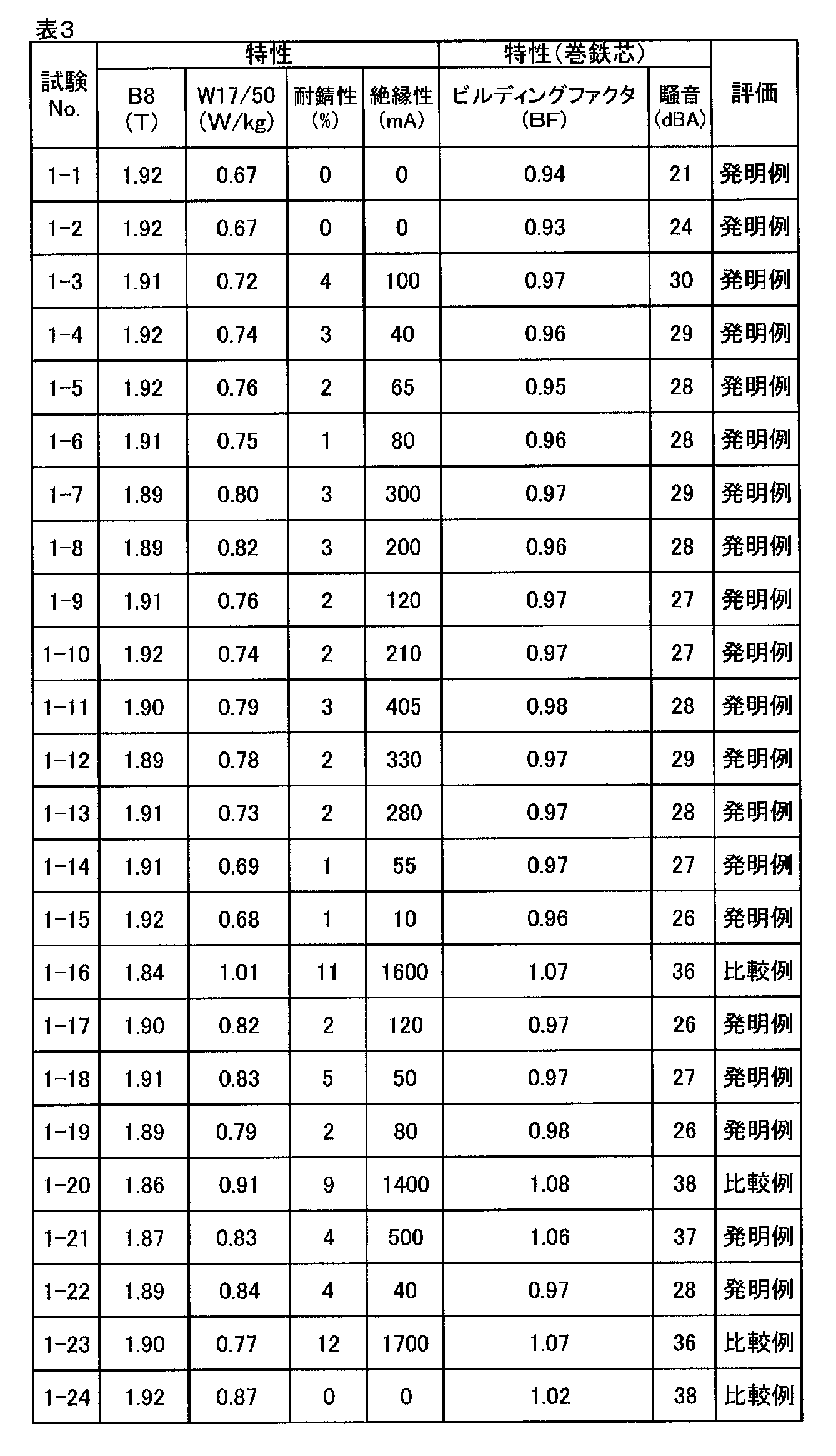
第2の実験例の鋼板は窒化焼鈍を含まないプロセスで製造するものである。表4~表6に詳細を示す。


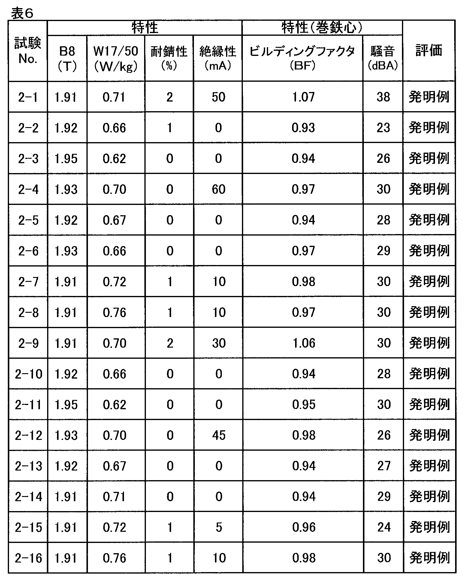
第3の実験例の鋼板は窒化焼鈍を含むプロセスで製造するものである。表7~表9に詳細を示す。
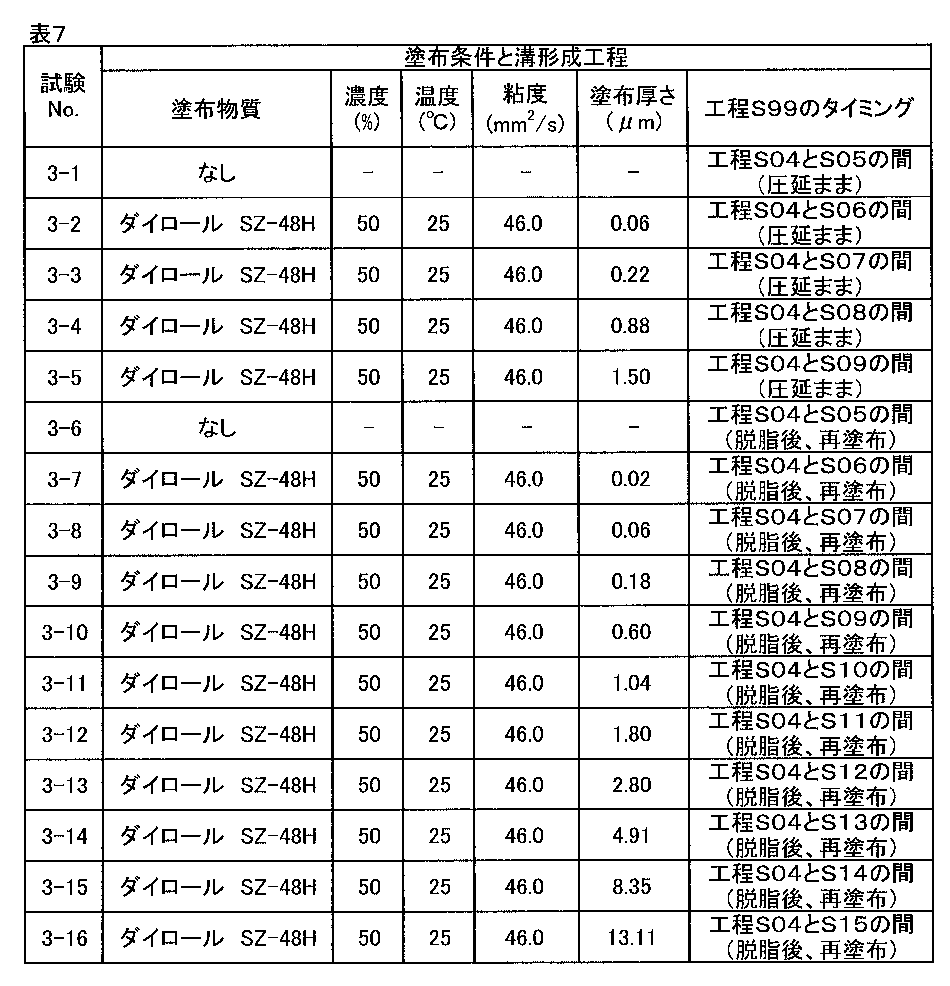

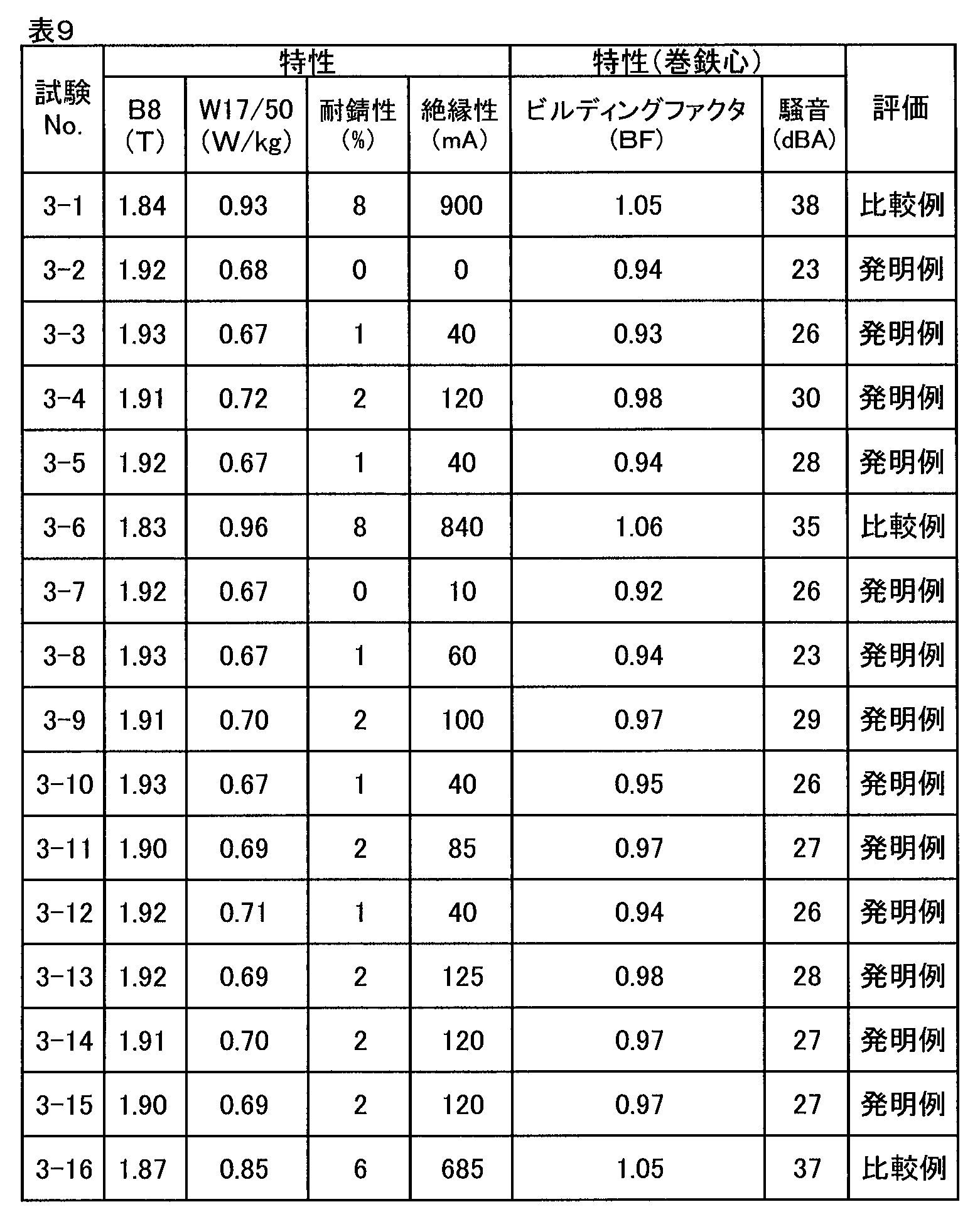
Claims (8)
- 延在方向が圧延方向と交差し、且つ深さ方向が板厚方向と平行な溝が形成された鋼板表面を有する鋼板を備え、
前記鋼板の表面の前記溝の両側に前記溝と平行に連なる溶融凝固物が存在し、
前記溝を含む特定領域内の前記鋼板表面を一定の間隔で測定した高さデータの高さ分布において最大度数となる高さを仮想平面とし、前記仮想平面より凹んだ凹部の空間体積をV1とし、前記仮想平面よりも突出した凸部の体積をV2としたとき、V2/V1の値が0.10超0.80未満であり、
前記特定領域内に複数の突起が形成されており、前記複数の突起のうちで、前記溝に最も近い突起の幅が他の突起の幅よりも大きく、
前記高さ分布において前記延在方向の平均高さが最も高い領域を延在方向及び板厚方向を含む溝長手断面で視た場合に、
当該領域の表面を成す粗さ曲線の平均粗さRaが、0.30~2.00μmであり、
当該領域の表面を成す粗さ曲線要素の平均長さRSmが、10~150μmであることを特徴とする方向性電磁鋼板。 - 前記の高さデータにおいて0.02%番目となる高さが、1超~10μmであることを特徴とする請求項1に記載の方向性電磁鋼板。
- 前記溝周辺の鋼板表面形状を、溝延在方向と垂直な溝短手断面で視た場合に、
前記凸部のうち、前記溝に最も近い突起の端部T1sと前記溝の端部mとの距離Lsが、0超~40μmであることを特徴とする請求項1又は2に記載の方向性電磁鋼板。 - 前記複数の突起のうちで、前記溝に最も近い突起の幅W1が、40μm以下であることを特徴とする請求項1乃至3のいずれか1項に記載の方向性電磁鋼板。
- 前記複数の突起のうちで、前記溝に最も近い突起の幅をW1、第n番目(nは2以上の整数)に近い突起の幅をWnと表したとき、Wn/W1の値が0.20超1.00未満であることを特徴とする請求項1乃至4のいずれか1項に記載の方向性電磁鋼板。
- 前記溝延在方向に垂直な断面において最も高い突起の底に存在する結晶粒の数が平均で10.0個以下であることを特徴とする請求項1乃至5のいずれか1項に記載の方向性電磁鋼板。
- 前記高さ分布において前記延在方向の平均高さが最も高い領域内の突起の金属組織の結晶方位について、{100}<001>方位の面積率が65%以上であることを特徴とする請求項1乃至6のいずれか1項に記載の方向性電磁鋼板。
- 前記凸部表面及び溝表面を含む前記鋼板表面上に、グラス皮膜を備えていることを特徴とする請求項1乃至7のいずれか1項に記載の方向性電磁鋼板。
Priority Applications (8)
| Application Number | Priority Date | Filing Date | Title |
|---|---|---|---|
| JP2018509660A JP6569803B2 (ja) | 2016-03-31 | 2017-03-31 | 方向性電磁鋼板 |
| EP17775544.4A EP3438293B1 (en) | 2016-03-31 | 2017-03-31 | Grain-oriented electrical steel sheet |
| PL17775544T PL3438293T3 (pl) | 2016-03-31 | 2017-03-31 | Blacha cienka ze stali elektrotechnicznej o ziarnach zorientowanych |
| RU2018133166A RU2699344C1 (ru) | 2016-03-31 | 2017-03-31 | Электротехнический стальной лист с ориентированной зеренной структурой |
| CN201780018735.9A CN108779510B (zh) | 2016-03-31 | 2017-03-31 | 方向性电磁钢板 |
| KR1020187026547A KR102091096B1 (ko) | 2016-03-31 | 2017-03-31 | 방향성 전자 강판 |
| US16/080,255 US10662491B2 (en) | 2016-03-31 | 2017-03-31 | Grain-oriented electrical steel sheet |
| BR112018067773-6A BR112018067773B1 (pt) | 2016-03-31 | 2017-03-31 | Chapa de aço elétrico orientada por grão |
Applications Claiming Priority (2)
| Application Number | Priority Date | Filing Date | Title |
|---|---|---|---|
| JP2016073151 | 2016-03-31 | ||
| JP2016-073151 | 2016-03-31 |
Publications (1)
| Publication Number | Publication Date |
|---|---|
| WO2017171013A1 true WO2017171013A1 (ja) | 2017-10-05 |
Family
ID=59965983
Family Applications (1)
| Application Number | Title | Priority Date | Filing Date |
|---|---|---|---|
| PCT/JP2017/013622 Ceased WO2017171013A1 (ja) | 2016-03-31 | 2017-03-31 | 方向性電磁鋼板 |
Country Status (9)
| Country | Link |
|---|---|
| US (1) | US10662491B2 (ja) |
| EP (1) | EP3438293B1 (ja) |
| JP (1) | JP6569803B2 (ja) |
| KR (1) | KR102091096B1 (ja) |
| CN (1) | CN108779510B (ja) |
| BR (1) | BR112018067773B1 (ja) |
| PL (1) | PL3438293T3 (ja) |
| RU (1) | RU2699344C1 (ja) |
| WO (1) | WO2017171013A1 (ja) |
Cited By (13)
| Publication number | Priority date | Publication date | Assignee | Title |
|---|---|---|---|---|
| WO2019156220A1 (ja) * | 2018-02-08 | 2019-08-15 | 日本製鉄株式会社 | 方向性電磁鋼板 |
| JP2020025077A (ja) * | 2018-08-02 | 2020-02-13 | 株式会社東芝 | 複数の扁平磁性金属粒子、圧粉材料及び回転電機 |
| CN113228207A (zh) * | 2018-12-25 | 2021-08-06 | 大赛璐美华株式会社 | 表面具有粗面化结构的稀土磁体前体或稀土磁体成型体、以及它们的制造方法 |
| WO2021250953A1 (ja) * | 2020-06-09 | 2021-12-16 | Jfeスチール株式会社 | 方向性電磁鋼板 |
| EP3901972A4 (en) * | 2018-12-19 | 2022-03-09 | Posco | CORNORATED ELECTRICAL STEEL AND METHOD OF PRODUCTION THEREOF |
| US11692250B2 (en) | 2018-08-02 | 2023-07-04 | Kabushiki Kaisha Toshiba | Plurality of flaky magnetic metal particles, pressed powder material, and rotating electric machine |
| WO2023140363A1 (ja) | 2022-01-20 | 2023-07-27 | 日本製鉄株式会社 | 方向性電磁鋼板、方向性電磁鋼板製造装置、及び方向性電磁鋼板製造方法 |
| JPWO2024075621A1 (ja) * | 2022-10-03 | 2024-04-11 | ||
| RU2817293C1 (ru) * | 2019-09-03 | 2024-04-12 | Ниппон Стил Корпорейшн | Ленточный сердечник |
| JPWO2024111641A1 (ja) * | 2022-11-22 | 2024-05-30 | ||
| WO2024111639A1 (ja) * | 2022-11-22 | 2024-05-30 | 日本製鉄株式会社 | 方向性電磁鋼板 |
| KR20250048816A (ko) | 2022-10-04 | 2025-04-10 | 닛폰세이테츠 가부시키가이샤 | 방향성 전자 강판 및 그 제조 방법 |
| US12500027B2 (en) | 2019-09-03 | 2025-12-16 | Nippon Steel Corporation | Wound core |
Families Citing this family (11)
| Publication number | Priority date | Publication date | Assignee | Title |
|---|---|---|---|---|
| KR20180112354A (ko) * | 2017-04-03 | 2018-10-12 | 삼성전기주식회사 | 자성 시트 및 이를 포함하는 무선 전력 충전 장치 |
| KR102221606B1 (ko) | 2018-11-30 | 2021-02-26 | 주식회사 포스코 | 방향성 전기강판 및 그의 제조 방법 |
| JP7230933B2 (ja) * | 2019-01-28 | 2023-03-01 | 日本製鉄株式会社 | 方向性電磁鋼板及びその製造方法 |
| TWI861185B (zh) | 2019-08-23 | 2024-11-11 | 日商Tocalo股份有限公司 | 表面處理方法 |
| JP7193047B2 (ja) * | 2020-10-26 | 2022-12-20 | 日本製鉄株式会社 | 巻鉄心、巻鉄心の製造方法及び巻鉄心製造装置 |
| JP7435486B2 (ja) * | 2021-01-18 | 2024-02-21 | Jfeスチール株式会社 | 方向性電磁鋼板およびその製造方法 |
| JP7533755B2 (ja) * | 2021-12-14 | 2024-08-14 | Jfeスチール株式会社 | 積層鉄心の製造方法 |
| JP7836392B2 (ja) * | 2022-10-04 | 2026-03-26 | 日本製鉄株式会社 | 方向性電磁鋼板およびその製造方法 |
| EP4625452A4 (en) * | 2022-11-22 | 2026-02-25 | Nippon Steel Corp | WRAPPLED CORE |
| KR20250090318A (ko) | 2022-11-22 | 2025-06-19 | 닛폰세이테츠 가부시키가이샤 | 방향성 전자 강판 |
| KR20240098885A (ko) * | 2022-12-21 | 2024-06-28 | 주식회사 포스코 | 방향성 전기강판 및 그의 제조 방법 |
Citations (3)
| Publication number | Priority date | Publication date | Assignee | Title |
|---|---|---|---|---|
| WO2012033197A1 (ja) * | 2010-09-09 | 2012-03-15 | 新日本製鐵株式会社 | 方向性電磁鋼板及びその製造方法 |
| JP2012087332A (ja) * | 2010-10-15 | 2012-05-10 | Nippon Steel Corp | 方向性電磁鋼板の製造方法 |
| WO2012172624A1 (ja) * | 2011-06-13 | 2012-12-20 | 新日鐵住金株式会社 | 一方向性電磁鋼板の製造方法 |
Family Cites Families (14)
| Publication number | Priority date | Publication date | Assignee | Title |
|---|---|---|---|---|
| JPS5234222B2 (ja) | 1972-02-04 | 1977-09-02 | ||
| JPH06100939A (ja) | 1992-08-05 | 1994-04-12 | Kawasaki Steel Corp | 低鉄損方向性電磁鋼板の製造方法 |
| KR960006448B1 (ko) | 1992-08-05 | 1996-05-16 | 가와사끼 세이데쓰 가부시끼가이샤 | 저철손 방향성 전자강판의 제조방법 |
| JP2563729B2 (ja) | 1992-08-07 | 1996-12-18 | 新日本製鐵株式会社 | パルスco2レーザを用いた方向性電磁鋼板の鉄損改善方法および装置 |
| EP1149924B1 (en) * | 2000-04-24 | 2009-07-15 | Nippon Steel Corporation | Grain-oriented electrical steel sheet excellent in magnetic properties |
| JP4510757B2 (ja) * | 2003-03-19 | 2010-07-28 | 新日本製鐵株式会社 | 磁気特性の優れた方向性電磁鋼板とその製造方法 |
| US9139886B2 (en) | 2010-04-01 | 2015-09-22 | Nippon Steel & Sumitomo Metal Corporation | Grain-oriented electrical steel sheet and method for producing same |
| RU2540244C2 (ru) * | 2010-08-06 | 2015-02-10 | ДжФЕ СТИЛ КОРПОРЕЙШН | Лист из текстурированной электротехнической стали |
| JP5853352B2 (ja) * | 2010-08-06 | 2016-02-09 | Jfeスチール株式会社 | 方向性電磁鋼板およびその製造方法 |
| JP5742294B2 (ja) | 2011-02-25 | 2015-07-01 | Jfeスチール株式会社 | 方向性電磁鋼板の製造方法 |
| KR101370634B1 (ko) * | 2011-12-29 | 2014-03-07 | 주식회사 포스코 | 전기강판 및 그 제조방법 |
| JP5935880B2 (ja) * | 2012-04-27 | 2016-06-15 | 新日鐵住金株式会社 | 方向性電磁鋼板及びその製造方法 |
| CN104755636B (zh) * | 2012-10-31 | 2016-10-19 | 杰富意钢铁株式会社 | 晶粒取向电磁钢板及其制造方法 |
| RU2501866C1 (ru) * | 2012-11-23 | 2013-12-20 | Владимир Иванович Пудов | Способ улучшения магнитных свойств анизотропной электротехнической стали лазерной обработкой |
-
2017
- 2017-03-31 PL PL17775544T patent/PL3438293T3/pl unknown
- 2017-03-31 BR BR112018067773-6A patent/BR112018067773B1/pt active IP Right Grant
- 2017-03-31 US US16/080,255 patent/US10662491B2/en active Active
- 2017-03-31 CN CN201780018735.9A patent/CN108779510B/zh active Active
- 2017-03-31 RU RU2018133166A patent/RU2699344C1/ru active
- 2017-03-31 JP JP2018509660A patent/JP6569803B2/ja active Active
- 2017-03-31 WO PCT/JP2017/013622 patent/WO2017171013A1/ja not_active Ceased
- 2017-03-31 KR KR1020187026547A patent/KR102091096B1/ko active Active
- 2017-03-31 EP EP17775544.4A patent/EP3438293B1/en active Active
Patent Citations (3)
| Publication number | Priority date | Publication date | Assignee | Title |
|---|---|---|---|---|
| WO2012033197A1 (ja) * | 2010-09-09 | 2012-03-15 | 新日本製鐵株式会社 | 方向性電磁鋼板及びその製造方法 |
| JP2012087332A (ja) * | 2010-10-15 | 2012-05-10 | Nippon Steel Corp | 方向性電磁鋼板の製造方法 |
| WO2012172624A1 (ja) * | 2011-06-13 | 2012-12-20 | 新日鐵住金株式会社 | 一方向性電磁鋼板の製造方法 |
Cited By (34)
| Publication number | Priority date | Publication date | Assignee | Title |
|---|---|---|---|---|
| JP7010311B2 (ja) | 2018-02-08 | 2022-02-10 | 日本製鉄株式会社 | 方向性電磁鋼板 |
| US11551838B2 (en) | 2018-02-08 | 2023-01-10 | Nippon Steel Corporation | Grain-oriented electrical steel sheet |
| KR20200103100A (ko) * | 2018-02-08 | 2020-09-01 | 닛폰세이테츠 가부시키가이샤 | 방향성 전자 강판 |
| CN111684087A (zh) * | 2018-02-08 | 2020-09-18 | 日本制铁株式会社 | 方向性电磁钢板 |
| JPWO2019156220A1 (ja) * | 2018-02-08 | 2021-02-04 | 日本製鉄株式会社 | 方向性電磁鋼板 |
| RU2749826C1 (ru) * | 2018-02-08 | 2021-06-17 | Ниппон Стил Корпорейшн | Лист электротехнической анизотропной стали |
| WO2019156220A1 (ja) * | 2018-02-08 | 2019-08-15 | 日本製鉄株式会社 | 方向性電磁鋼板 |
| EP3751014A4 (en) * | 2018-02-08 | 2021-10-06 | Nippon Steel Corporation | GRAIN ORIENTED ELECTRIC STEEL SHEET |
| KR102483111B1 (ko) | 2018-02-08 | 2022-12-30 | 닛폰세이테츠 가부시키가이샤 | 방향성 전자 강판 |
| US11692250B2 (en) | 2018-08-02 | 2023-07-04 | Kabushiki Kaisha Toshiba | Plurality of flaky magnetic metal particles, pressed powder material, and rotating electric machine |
| JP2020025077A (ja) * | 2018-08-02 | 2020-02-13 | 株式会社東芝 | 複数の扁平磁性金属粒子、圧粉材料及び回転電機 |
| US12049686B2 (en) | 2018-08-02 | 2024-07-30 | Kabushiki Kaisha Toshiba | Plurality of flaky magnetic metal particles, pressed powder material, and rotating electric machine |
| JP7258646B2 (ja) | 2018-08-02 | 2023-04-17 | 株式会社東芝 | 複数の扁平磁性金属粒子、圧粉材料及び回転電機 |
| EP3901972A4 (en) * | 2018-12-19 | 2022-03-09 | Posco | CORNORATED ELECTRICAL STEEL AND METHOD OF PRODUCTION THEREOF |
| US12084736B2 (en) | 2018-12-19 | 2024-09-10 | Posco Co., Ltd | Grain-oriented electrical steel sheet and manufacturing method therefor |
| CN113228207A (zh) * | 2018-12-25 | 2021-08-06 | 大赛璐美华株式会社 | 表面具有粗面化结构的稀土磁体前体或稀土磁体成型体、以及它们的制造方法 |
| CN113228207B (zh) * | 2018-12-25 | 2023-08-01 | 大赛璐美华株式会社 | 表面具有粗面化结构的稀土磁体前体或稀土磁体成型体、以及它们的制造方法 |
| US12500027B2 (en) | 2019-09-03 | 2025-12-16 | Nippon Steel Corporation | Wound core |
| RU2817293C1 (ru) * | 2019-09-03 | 2024-04-12 | Ниппон Стил Корпорейшн | Ленточный сердечник |
| JP2021195571A (ja) * | 2020-06-09 | 2021-12-27 | Jfeスチール株式会社 | 方向性電磁鋼板 |
| WO2021250953A1 (ja) * | 2020-06-09 | 2021-12-16 | Jfeスチール株式会社 | 方向性電磁鋼板 |
| US11990261B2 (en) | 2020-06-09 | 2024-05-21 | Jfe Steel Corporation | Grain-oriented electrical steel sheet |
| WO2023140363A1 (ja) | 2022-01-20 | 2023-07-27 | 日本製鉄株式会社 | 方向性電磁鋼板、方向性電磁鋼板製造装置、及び方向性電磁鋼板製造方法 |
| KR20240110624A (ko) | 2022-01-20 | 2024-07-15 | 닛폰세이테츠 가부시키가이샤 | 방향성 전자 강판, 방향성 전자 강판 제조 장치, 및 방향성 전자 강판 제조 방법 |
| WO2024075621A1 (ja) * | 2022-10-03 | 2024-04-11 | 日本製鉄株式会社 | 積鉄心および積鉄心の製造方法 |
| JPWO2024075621A1 (ja) * | 2022-10-03 | 2024-04-11 | ||
| JP7801644B2 (ja) | 2022-10-03 | 2026-01-19 | 日本製鉄株式会社 | 積鉄心および積鉄心の製造方法 |
| KR20250048816A (ko) | 2022-10-04 | 2025-04-10 | 닛폰세이테츠 가부시키가이샤 | 방향성 전자 강판 및 그 제조 방법 |
| WO2024111641A1 (ja) * | 2022-11-22 | 2024-05-30 | 日本製鉄株式会社 | 方向性電磁鋼板及びその製造方法 |
| WO2024111639A1 (ja) * | 2022-11-22 | 2024-05-30 | 日本製鉄株式会社 | 方向性電磁鋼板 |
| JPWO2024111641A1 (ja) * | 2022-11-22 | 2024-05-30 | ||
| JP7712588B2 (ja) | 2022-11-22 | 2025-07-24 | 日本製鉄株式会社 | 方向性電磁鋼板及びその製造方法 |
| RU2854669C2 (ru) * | 2022-11-22 | 2026-01-15 | Ниппон Стил Корпорейшн | Лист анизотропной электротехнической стали и способ его производства |
| EP4624615A4 (en) * | 2022-11-22 | 2026-04-22 | Nippon Steel Corp | GRAIN-ORIENTED ELECTROMAGNETIC STEEL SHEET, AND METHOD FOR MANUFACTURED THEREOF |
Also Published As
| Publication number | Publication date |
|---|---|
| US10662491B2 (en) | 2020-05-26 |
| EP3438293A4 (en) | 2019-08-28 |
| EP3438293B1 (en) | 2020-07-29 |
| US20190048434A1 (en) | 2019-02-14 |
| EP3438293A1 (en) | 2019-02-06 |
| PL3438293T3 (pl) | 2020-12-14 |
| BR112018067773A2 (pt) | 2019-01-15 |
| JP6569803B2 (ja) | 2019-09-04 |
| RU2699344C1 (ru) | 2019-09-04 |
| JPWO2017171013A1 (ja) | 2019-01-10 |
| CN108779510B (zh) | 2020-01-24 |
| CN108779510A (zh) | 2018-11-09 |
| BR112018067773B1 (pt) | 2022-04-26 |
| KR102091096B1 (ko) | 2020-03-19 |
| KR20180108838A (ko) | 2018-10-04 |
Similar Documents
| Publication | Publication Date | Title |
|---|---|---|
| JP6569803B2 (ja) | 方向性電磁鋼板 | |
| CN107406903B (zh) | 方向性电磁钢板 | |
| JP6418322B2 (ja) | 方向性電磁鋼板 | |
| JP6409960B2 (ja) | 方向性電磁鋼板 | |
| JP6455593B2 (ja) | 方向性電磁鋼板 | |
| RU2746618C1 (ru) | Способ получения стойкой при отжиге для снятия напряжений, текстурированной кремнистой стали с низкими потерями в железе | |
| WO2018177007A1 (zh) | 一种耐消除应力退火的激光刻痕取向硅钢及其制造方法。 | |
| JP5928607B2 (ja) | 方向性電磁鋼板及び方向性電磁鋼板の製造方法 | |
| WO2024075788A1 (ja) | 方向性電磁鋼板およびその製造方法 | |
| JP7040584B1 (ja) | 金属ストリップ表面への溝形成方法、および方向性電磁鋼板の製造方法 | |
| WO2023112421A1 (ja) | 方向性電磁鋼板およびその製造方法 |
Legal Events
| Date | Code | Title | Description |
|---|---|---|---|
| WWE | Wipo information: entry into national phase |
Ref document number: 2018509660 Country of ref document: JP |
|
| ENP | Entry into the national phase |
Ref document number: 20187026547 Country of ref document: KR Kind code of ref document: A |
|
| WWE | Wipo information: entry into national phase |
Ref document number: 1020187026547 Country of ref document: KR |
|
| NENP | Non-entry into the national phase |
Ref country code: DE |
|
| REG | Reference to national code |
Ref country code: BR Ref legal event code: B01A Ref document number: 112018067773 Country of ref document: BR |
|
| WWE | Wipo information: entry into national phase |
Ref document number: 2017775544 Country of ref document: EP |
|
| ENP | Entry into the national phase |
Ref document number: 2017775544 Country of ref document: EP Effective date: 20181031 |
|
| 121 | Ep: the epo has been informed by wipo that ep was designated in this application |
Ref document number: 17775544 Country of ref document: EP Kind code of ref document: A1 |
|
| ENP | Entry into the national phase |
Ref document number: 112018067773 Country of ref document: BR Kind code of ref document: A2 Effective date: 20180904 |