WO2017171471A1 - 강화막, 이를 포함하는 전기화학 전지 및 연료 전지, 및 상기 강화막의 제조방법 - Google Patents
강화막, 이를 포함하는 전기화학 전지 및 연료 전지, 및 상기 강화막의 제조방법 Download PDFInfo
- Publication number
- WO2017171471A1 WO2017171471A1 PCT/KR2017/003553 KR2017003553W WO2017171471A1 WO 2017171471 A1 WO2017171471 A1 WO 2017171471A1 KR 2017003553 W KR2017003553 W KR 2017003553W WO 2017171471 A1 WO2017171471 A1 WO 2017171471A1
- Authority
- WO
- WIPO (PCT)
- Prior art keywords
- porous polymer
- platinum
- support
- porous
- polymer
- Prior art date
- Legal status (The legal status is an assumption and is not a legal conclusion. Google has not performed a legal analysis and makes no representation as to the accuracy of the status listed.)
- Ceased
Links
Images



Classifications
-
- H—ELECTRICITY
- H01—ELECTRIC ELEMENTS
- H01M—PROCESSES OR MEANS, e.g. BATTERIES, FOR THE DIRECT CONVERSION OF CHEMICAL ENERGY INTO ELECTRICAL ENERGY
- H01M8/00—Fuel cells; Manufacture thereof
- H01M8/10—Fuel cells with solid electrolytes
- H01M8/1004—Fuel cells with solid electrolytes characterised by membrane-electrode assemblies [MEA]
-
- H—ELECTRICITY
- H01—ELECTRIC ELEMENTS
- H01M—PROCESSES OR MEANS, e.g. BATTERIES, FOR THE DIRECT CONVERSION OF CHEMICAL ENERGY INTO ELECTRICAL ENERGY
- H01M8/00—Fuel cells; Manufacture thereof
- H01M8/10—Fuel cells with solid electrolytes
- H01M8/1016—Fuel cells with solid electrolytes characterised by the electrolyte material
- H01M8/1018—Polymeric electrolyte materials
- H01M8/1041—Polymer electrolyte composites, mixtures or blends
- H01M8/1055—Inorganic layers on the polymer electrolytes, e.g. inorganic coatings
-
- H—ELECTRICITY
- H01—ELECTRIC ELEMENTS
- H01M—PROCESSES OR MEANS, e.g. BATTERIES, FOR THE DIRECT CONVERSION OF CHEMICAL ENERGY INTO ELECTRICAL ENERGY
- H01M4/00—Electrodes
- H01M4/86—Inert electrodes with catalytic activity, e.g. for fuel cells
- H01M4/88—Processes of manufacture
- H01M4/8803—Supports for the deposition of the catalytic active composition
- H01M4/8807—Gas diffusion layers
-
- H—ELECTRICITY
- H01—ELECTRIC ELEMENTS
- H01M—PROCESSES OR MEANS, e.g. BATTERIES, FOR THE DIRECT CONVERSION OF CHEMICAL ENERGY INTO ELECTRICAL ENERGY
- H01M4/00—Electrodes
- H01M4/86—Inert electrodes with catalytic activity, e.g. for fuel cells
- H01M4/88—Processes of manufacture
- H01M4/8825—Methods for deposition of the catalytic active composition
- H01M4/8846—Impregnation
-
- H—ELECTRICITY
- H01—ELECTRIC ELEMENTS
- H01M—PROCESSES OR MEANS, e.g. BATTERIES, FOR THE DIRECT CONVERSION OF CHEMICAL ENERGY INTO ELECTRICAL ENERGY
- H01M4/00—Electrodes
- H01M4/86—Inert electrodes with catalytic activity, e.g. for fuel cells
- H01M4/90—Selection of catalytic material
- H01M4/92—Metals of platinum group
- H01M4/928—Unsupported catalytic particles; loose particulate catalytic materials, e.g. in fluidised state
-
- H—ELECTRICITY
- H01—ELECTRIC ELEMENTS
- H01M—PROCESSES OR MEANS, e.g. BATTERIES, FOR THE DIRECT CONVERSION OF CHEMICAL ENERGY INTO ELECTRICAL ENERGY
- H01M8/00—Fuel cells; Manufacture thereof
- H01M8/10—Fuel cells with solid electrolytes
- H01M8/1016—Fuel cells with solid electrolytes characterised by the electrolyte material
- H01M8/1018—Polymeric electrolyte materials
-
- H—ELECTRICITY
- H01—ELECTRIC ELEMENTS
- H01M—PROCESSES OR MEANS, e.g. BATTERIES, FOR THE DIRECT CONVERSION OF CHEMICAL ENERGY INTO ELECTRICAL ENERGY
- H01M8/00—Fuel cells; Manufacture thereof
- H01M8/10—Fuel cells with solid electrolytes
- H01M8/1016—Fuel cells with solid electrolytes characterised by the electrolyte material
- H01M8/1018—Polymeric electrolyte materials
- H01M8/1041—Polymer electrolyte composites, mixtures or blends
- H01M8/1044—Mixtures of polymers, of which at least one is ionically conductive
-
- H—ELECTRICITY
- H01—ELECTRIC ELEMENTS
- H01M—PROCESSES OR MEANS, e.g. BATTERIES, FOR THE DIRECT CONVERSION OF CHEMICAL ENERGY INTO ELECTRICAL ENERGY
- H01M8/00—Fuel cells; Manufacture thereof
- H01M8/10—Fuel cells with solid electrolytes
- H01M8/1016—Fuel cells with solid electrolytes characterised by the electrolyte material
- H01M8/1018—Polymeric electrolyte materials
- H01M8/1058—Polymeric electrolyte materials characterised by a porous support having no ion-conducting properties
- H01M8/1062—Polymeric electrolyte materials characterised by a porous support having no ion-conducting properties characterised by the physical properties of the porous support, e.g. its porosity or thickness
-
- H—ELECTRICITY
- H01—ELECTRIC ELEMENTS
- H01M—PROCESSES OR MEANS, e.g. BATTERIES, FOR THE DIRECT CONVERSION OF CHEMICAL ENERGY INTO ELECTRICAL ENERGY
- H01M4/00—Electrodes
- H01M4/86—Inert electrodes with catalytic activity, e.g. for fuel cells
- H01M2004/8678—Inert electrodes with catalytic activity, e.g. for fuel cells characterised by the polarity
- H01M2004/8684—Negative electrodes
-
- H—ELECTRICITY
- H01—ELECTRIC ELEMENTS
- H01M—PROCESSES OR MEANS, e.g. BATTERIES, FOR THE DIRECT CONVERSION OF CHEMICAL ENERGY INTO ELECTRICAL ENERGY
- H01M4/00—Electrodes
- H01M4/86—Inert electrodes with catalytic activity, e.g. for fuel cells
- H01M2004/8678—Inert electrodes with catalytic activity, e.g. for fuel cells characterised by the polarity
- H01M2004/8689—Positive electrodes
-
- H—ELECTRICITY
- H01—ELECTRIC ELEMENTS
- H01M—PROCESSES OR MEANS, e.g. BATTERIES, FOR THE DIRECT CONVERSION OF CHEMICAL ENERGY INTO ELECTRICAL ENERGY
- H01M8/00—Fuel cells; Manufacture thereof
- H01M8/10—Fuel cells with solid electrolytes
- H01M2008/1095—Fuel cells with polymeric electrolytes
-
- Y—GENERAL TAGGING OF NEW TECHNOLOGICAL DEVELOPMENTS; GENERAL TAGGING OF CROSS-SECTIONAL TECHNOLOGIES SPANNING OVER SEVERAL SECTIONS OF THE IPC; TECHNICAL SUBJECTS COVERED BY FORMER USPC CROSS-REFERENCE ART COLLECTIONS [XRACs] AND DIGESTS
- Y02—TECHNOLOGIES OR APPLICATIONS FOR MITIGATION OR ADAPTATION AGAINST CLIMATE CHANGE
- Y02E—REDUCTION OF GREENHOUSE GAS [GHG] EMISSIONS, RELATED TO ENERGY GENERATION, TRANSMISSION OR DISTRIBUTION
- Y02E60/00—Enabling technologies; Technologies with a potential or indirect contribution to GHG emissions mitigation
- Y02E60/30—Hydrogen technology
- Y02E60/50—Fuel cells
-
- Y—GENERAL TAGGING OF NEW TECHNOLOGICAL DEVELOPMENTS; GENERAL TAGGING OF CROSS-SECTIONAL TECHNOLOGIES SPANNING OVER SEVERAL SECTIONS OF THE IPC; TECHNICAL SUBJECTS COVERED BY FORMER USPC CROSS-REFERENCE ART COLLECTIONS [XRACs] AND DIGESTS
- Y02—TECHNOLOGIES OR APPLICATIONS FOR MITIGATION OR ADAPTATION AGAINST CLIMATE CHANGE
- Y02P—CLIMATE CHANGE MITIGATION TECHNOLOGIES IN THE PRODUCTION OR PROCESSING OF GOODS
- Y02P70/00—Climate change mitigation technologies in the production process for final industrial or consumer products
- Y02P70/50—Manufacturing or production processes characterised by the final manufactured product
Definitions
- the present specification relates to a reinforcing film, an electrochemical cell and a fuel cell including the same, and a manufacturing method of the reinforcing film.
- Reinforced membrane is used in the field that needs ion exchange capacity, such as batteries, sensors, etc.
- the reinforcement membrane is used as an ion exchange membrane such as fuel cells, chemical sensors, flow batteries.
- fuel cells are highly efficient, do not emit pollutants such as NOx and SOx, and abundant fuels are used. Along with this, research on the reinforcement membrane provided as the polymer electrolyte membrane of the fuel cell is also required.
- the flow battery is a secondary battery that is charged and discharged while circulating the electrolyte in which energy is stored, and research on the flow battery is being actively conducted along with the reinforcing film provided as the electrolyte membrane of the flow.
- the present specification provides a reinforcing film, an electrochemical cell and a fuel cell including the same, and a manufacturing method of the reinforcing film.
- the present specification is an anode; Cathode; And it provides an electrochemical cell comprising the reinforcing film provided between the anode and the cathode.
- the present specification is an anode; Cathode; And it provides a membrane electrode assembly comprising the reinforcement film provided between the anode and the cathode.
- the present disclosure provides a fuel cell including the membrane electrode assembly.
- the present specification is a step of impregnating a porous polymer support in a solution containing a precursor of platinum nanoparticles, to form platinum nanoparticles dispersed on both surfaces of the porous polymer support and the surface within the pores; And forming an ion conductive polymer in the pores of the porous polymer support provided on the surface of the platinum nanoparticles, wherein the average diameter of the platinum nanoparticles is 1 nm or more and 50 nm or less.
- the phenomenon in which the impregnated ion conductive polymer impregnation liquid is dewetted from the porous support can be reduced.
- the reinforcing membrane may be impregnated with an ion conductive polymer evenly in the porous support.
- the reinforcing film of one embodiment of the present specification has a self-humidifying function of generating water using hydrogen and oxygen that crossover the reinforcing film.
- FIG. 1 is a schematic diagram illustrating a principle of electricity generation of a fuel cell.
- FIG. 2 is a view schematically showing the structure of a membrane electrode assembly for a fuel cell.
- FIG 3 is a view schematically showing an embodiment of a fuel cell.
- FIG. 4 is a cross-sectional view of a membrane electrode assembly according to one embodiment of the present specification.
- Figure 5 shows the voltage according to the current density of the membrane electrode assembly according to the embodiment and the comparative example at 100% relative humidity (RH).
- Figure 6 shows the voltage according to the current density of the membrane electrode assembly according to the embodiment and the comparative example at 50% relative humidity (RH).
- FIG. 8 shows current density values at 0.6V of the membrane electrode assembly according to the examples and the comparative examples at 50% / 32% relative humidity (RH).
- 9 is an electron scanning micrograph of the surface and cross section of the porous support of the embodiment.
- FIG. 11 shows the results of calculating the respective surface energies by measuring contact angles of water and diiodomethane droplets placed on porous supports of Examples and Comparative Examples.
- porous polymer support provides a reinforcing film comprising a platinum layer provided on the surface of the porous polymer support and the ion conductive polymer provided in the pores of the porous polymer support.
- a porous polymer support Platinum nanoparticles dispersed on both surfaces of the porous polymer support and in the pores; And it comprises an ion conductive polymer provided in the pores of the porous polymer support, the platinum nanoparticles provide a reinforcing film that is 1nm or more and 50nm or less.
- the porous polymer support may include polyimide (PI), nylon, polyethylene terephthalate (PET), polytetrafluoro ethylene (PTFE), polyethylene (PE), and polypropylene.
- PI polyimide
- PET polyethylene terephthalate
- PTFE polytetrafluoro ethylene
- PE polyethylene
- PEEK polyetheretherketone
- the porous polymer support may include a polyolefin-based polymer, and specifically, the porous polymer support may include a polyolefin-based polymer including at least one of polyethylene, polypropylene, and polyisobutylene.
- Individual diameters of pores of the porous polymer support may be 1 nm or more and 50 ⁇ m or less. Specifically, the individual diameters of the pores of the porous polymer support may be 10 nm or more and 1 ⁇ m or less, and preferably, the individual diameters of the pores of the porous polymer support may be 50 nm or more and 500 nm or less. More dense pores than large pores have the advantage of increased air permeability and durability.
- the method for measuring the individual diameter of the pores of the porous polymer support is not particularly limited, and a method used in the art may be employed, for example, the diameter of the pores may be measured through an electron microscope.
- the porosity of the porous polymer support may be 50% or more and 95% or less.
- the ion channel is well formed when the ion conductive polymer is impregnated into the pores of the porous polymer support.
- the thickness of the porous polymer support is not particularly limited, but may be 1 ⁇ m or more and 20 ⁇ m or less.
- the platinum layer may include platinum nanoparticles provided on both surfaces of the porous polymer support and in the pores.
- the self-humidifying function of the electrolyte membrane may be introduced through the platinum nanoparticles evenly dispersed in the reinforcing membrane.
- the platinum particles in the reinforcing film may act as a catalyst to generate hydrogen and oxygen that crossover the reinforcing film.
- the platinum layer may increase the impregnation degree of the ion conductive polymer on the reinforcing substrate through the surface energy of the reinforcing substrate.
- the average diameter of the platinum nanoparticles may be 1nm or more and 50nm or less.
- the resistance to ion transfer in the reinforcing film may be the size having the maximum catalytic activity while minimizing.
- the average diameter of the platinum nanoparticles may be 1nm or more and 30nm or less, more specifically 1nm or more and 10nm or less.
- the individual diameter of the platinum nanoparticles may be more than 0nm 100nm or less, specifically, more than 0nm 50nm or less, more specifically may be more than 0nm 30nm or less.
- the diameter means the longest distance from one point on the surface of the platinum nanoparticles to the other in the image measured through the electron microscope.
- the ion conductive polymer may be provided in the pores of the porous polymer support. Specifically, the ion conductive polymer may be provided in the pores of the porous polymer support provided with a platinum layer.
- the ion conductive polymer is a surface of the platinum nanoparticles provided in the pores of the porous polymer support, and the platinum nanoparticles and the platinum nanoparticles In other words it may be provided in the pores of the porous polymer support is not provided with platinum nanoparticles.
- the surface energy of the surface of the porous polymer support is higher than that of the support having no pores of the same material, so that the porous polymer support does not evenly penetrate the ion conductive polymer in the pores of the porous polymer support or by the repulsive force. Dewetting to the surface of the substrate may occur.
- the porous polymer support provided with the platinum layer of the present invention has good affinity with the ion conductive polymer so that the ion conductive polymer can be evenly impregnated in the pores of the porous polymer support.
- the ion conductive polymer is not particularly limited as long as it is a material capable of ion exchange, and generally used in the art may be used.
- the ion conductive polymer may be a hydrocarbon-based polymer, a partial fluorine-based polymer or a fluorine-based polymer.
- the hydrocarbon-based polymer may be a hydrocarbon-based sulfonated polymer without a fluorine group, on the contrary, the fluorine-based polymer may be a sulfonated polymer saturated with a fluorine group, and the partial fluorine-based polymer may not be saturated with a fluorine group. Sulfonated polymer.
- the ion conductive polymer may be a perfluorosulfonic acid polymer, a hydrocarbon polymer, an aromatic sulfone polymer, an aromatic ketone polymer, a polybenzimidazole polymer, a polystyrene polymer, a polyester polymer, a polyimide polymer, polyvinylidene fluoride Ride type polymer, polyether sulfone type polymer, polyphenylene sulfide type polymer, polyphenylene oxide type polymer, polyphosphazene type polymer, polyethylene naphthalate type polymer, polyester type polymer, doped polybenzimidazole type polymer, It may be one or two or more polymers selected from the group consisting of polyether ketone polymer, polyether ether ketone polymer, polyphenylquinoxaline polymer, polysulfone polymer, polypyrrole polymer and polyaniline polymer.
- the polymer may be used by sulfonated and may be a single copolymer, an alternating copolymer, a random copolymer, a block copolymer, a multiblock copolymer or a graft copolymer, but is not limited thereto.
- the ion conductive polymer may be a polymer having a cationic conductivity, for example, perfluorosulfonic acid-based polymer, sulfonated polyetheretherketone (sPEEK), sulfonated polyetherketone (sPEK, sulfonated (polyetherketone)) Polyvinylidene fluoride-graft-poly (styrene sulfonic acid), PVDF-g-PSSA, and sulfonated polyfluorenyl ether ketone It may include at least one of)).
- sPEEK sulfonated polyetheretherketone
- sPEK sulfonated polyetherketone
- PVDF-g-PSSA polyvinylidene fluoride-graft-poly (styrene sulfonic acid)
- the content of the porous polymer support may be 5 wt% or more and 50 wt% or less.
- the content of the platinum layer may be 0.1% by weight or more and 10% by weight or less.
- the resistance to ion transfer in the reinforcing layer may be the size having the maximum self-humidity and dewetting ability while minimizing.
- the content of the ion conductive polymer may be 45% by weight or more and 90% by weight or less, specifically, 45% by weight or more and 90% by weight or less, preferably 50% by weight or more and 90% by weight. It may be less than or equal to%.
- the present specification is an anode; Cathode; And it provides an electrochemical cell comprising the reinforcing film provided between the anode and the cathode.
- the cathode may refer to an electrode that receives electrons when discharged and is reduced, and may be an anode (oxide electrode) that is oxidized and discharges electrons when charged.
- the anode may refer to an electrode that is oxidized when discharged and emits electrons, and may be a cathode (reduction electrode) that receives and reduces electrons when charged.
- the electrochemical cell means a battery using a chemical reaction, and if the polymer electrolyte membrane is provided, the type thereof is not particularly limited.
- the electrochemical cell may be a fuel cell, a metal secondary battery, or a flow battery.
- the present specification provides an electrochemical cell module that includes an electrochemical cell as a unit cell.
- the electrochemical cell module may be formed by inserting and stacking a bipolar plate between unit cells according to one embodiment of the present application.
- the battery module may be used as a power source for an electric vehicle, a hybrid electric vehicle, a plug-in hybrid electric vehicle, or a power storage device.
- the present specification provides a membrane electrode assembly comprising an anode, a cathode, and the reinforcement film provided between the anode and the cathode.
- the present specification provides a fuel cell including the membrane electrode assembly.
- FIG. 1 schematically illustrates the principle of electricity generation of a fuel cell.
- the most basic unit for generating electricity is a membrane electrode assembly (MEA), which is an electrolyte membrane (M) and the electrolyte membrane (M). It consists of an anode (A) and a cathode (C) formed on both sides of the.
- MEA membrane electrode assembly
- An oxidation reaction of a fuel (F) such as hydrogen or a hydrocarbon such as methanol and butane occurs to generate hydrogen ions (H + ) and electrons (e ⁇ ).
- hydrogen ions move to the cathode C through the electrolyte membrane M.
- the cathode C reacts with hydrogen ions transferred through the electrolyte membrane M, an oxidizing agent O such as oxygen, and electrons to generate water W. This reaction causes the movement of electrons in the external circuit.
- FIG. 2 schematically shows the structure of a fuel cell membrane electrode assembly, wherein the fuel cell membrane electrode assembly includes an electrolyte membrane 10 and a cathode 50 positioned to face each other with the electrolyte membrane 10 therebetween;
- An anode 51 may be provided.
- the cathode is provided with a cathode catalyst layer 20 and a cathode gas diffusion layer 40 sequentially from the electrolyte membrane 10, and the anode is provided with an anode catalyst layer 21 and an anode gas diffusion layer 41 sequentially from the electrolyte membrane 10. It may be provided.
- FIG. 3 schematically illustrates the structure of a fuel cell, in which the fuel cell includes a stack 60, an oxidant supply unit 70, and a fuel supply unit 80.
- the stack 60 includes one or two or more membrane electrode assemblies as described above, and includes two or more separators interposed therebetween when two or more membrane electrode assemblies are included.
- the separator serves to prevent the membrane electrode assemblies from being electrically connected and to transfer fuel and oxidant supplied from the outside to the membrane electrode assembly.
- the oxidant supply unit 70 serves to supply the oxidant to the stack 60.
- Oxygen is typically used as the oxidant, and may be used by injecting oxygen or air into the oxidant supply unit 70.
- the fuel supply unit 80 serves to supply fuel to the stack 60, and to the fuel tank 81 storing fuel and the pump 82 supplying fuel stored in the fuel tank 81 to the stack 60.
- fuel hydrogen or hydrocarbon fuel in gas or liquid state may be used.
- hydrocarbon fuels include methanol, ethanol, propanol, butanol or natural gas.
- the manufacturing method of the reinforcing film may be cited above with respect to the reinforcing film.
- the method of manufacturing the reinforcing film may include forming a platinum layer on the surface of the porous polymer support.
- Forming the platinum layer may include impregnating a porous polymer support in a first solution containing a precursor of platinum nanoparticles.
- the platinum nanoparticles refer to nanoparticles containing a platinum element, and the precursor of the platinum nanoparticles may include at least one of precursors containing platinum elements.
- the precursor refers to the material of the step before becoming a specific material in the chemical reaction, specifically, the material of the previous step of the platinum metal.
- the first solution may further include at least one of a solvent, a dispersant, and a reducing agent.
- the content of the precursor of the platinum nanoparticles may be 0.01% by weight or more and 10% by weight or less of the weight of the porous polymer support, specifically, 0.01% by weight or more and 5% by weight or less of the weight of the porous polymer support.
- the content of the precursor of the platinum nanoparticles may be 0.01% by weight or more and 10% by weight or less.
- the content of the solvent may be 80% by weight or more and 90% by weight or less.
- the content of the dispersant may be 0.01% by weight or more and 10% by weight or less.
- the forming of the platinum layer may further include heating the first solution, in which case the final temperature may be 30 ° C. or more and 100 ° C. or less.
- Forming the platinum layer comprises the steps of preparing a porous polymer support; Impregnating the porous polymer support into a first solution comprising a precursor of platinum nanoparticles; Reducing the precursor of the platinum nanoparticles; And drying the porous polymer support.
- the preparing of the porous polymer support may include preparing the porous polymer support or purchasing and preparing the prepared porous polymer support.
- the method may further include pretreating an inner surface of the porous polymer support before impregnating the first solution in the porous polymer support.
- the pretreatment step of the porous polymer support may include impregnating the porous polymer support with a pretreatment solvent.
- the pretreatment solvent is not particularly limited, and may include at least one of an alcohol solvent such as methanol and ethanol and a polyol solvent such as ethylene glycol.
- Reducing the precursor of the platinum nanoparticles may be added to the reducing agent to reduce the precursor of the platinum nanoparticles to the platinum nanoparticles.
- the reducing agent used is not particularly limited, but may be, for example, one or two or more selected from the group consisting of NaBH 4 , NH 2 NH 2 , LiAlH 4 and LiBEt 3 H.
- the method of manufacturing the reinforcing film may include forming an ion conductive polymer in the pores of the porous polymer support provided on the surface of the platinum layer.
- Forming the ion conductive polymer may include impregnating a porous polymer support having a surface of the platinum layer in a second solution containing an ion conductive polymer.
- the method of impregnating the solution into the porous polymer support is not particularly limited, and the porous polymer support is placed in a bath containing the solution, or the solution is applied to one or both sides of the porous polymer support so that the solution penetrates into the pores of the porous polymer support. Can be pressurized.
- the second solution may further include a solvent.
- the content of the ion conductive polymer may be 1% by weight or more and 20% by weight or less.
- the content of the solvent may be 80% by weight or more and 99% by weight or less.
- the viscosity of the second solution may be adjusted according to the type, molecular weight, concentration, and type of solvent of the ion conductive polymer, and may be, for example, 10 cP or more and 500 cP or less. In this case, it is possible to have the maximum conductivity of ions while maintaining a crossover ratio of a predetermined value or more for fuel.
- Hydroquinonesulfonic acid potassium salt (0.9eq.), 4,4'-difluorobenzophenone (4,4 ') in a 1 L round-bottomed flask with Dean-Stark trap and condenser -difluorobenzophenone) (0.97eq.) and 3,5-bis (4-fluorobenzoyl) phenyl (4-fluorophenyl) methanone (3,5-bis (4-fluorobenzoyl) phenyl (4-fluorophenyl) methanone) (0.02eq.) was added and prepared in a nitrogen atmosphere using dimethyl sulfoxide (DMSO, dimethyl sulfoxide) and potassium carbonate (K 2 CO 3 , potassium carbonate) as a catalyst.
- DMSO dimethyl sulfoxide
- K 2 CO 3 potassium carbonate
- the reaction mixture was then stirred for 4 hours in an oil bath at 140 ° C. to remove the azeotrope by adsorption of the azeotrope to the molecular sieves of the Dean-Stark apparatus while the benzene was refluxed. It heated up at 180 degreeC and made it polycondensate for 20 hours. After the reaction was completed, the temperature of the reactant was reduced to 60 ° C., and then 4,4′-difluorobenzophenone (0.2275eq.) And 9,9-bis (hydride) were added to the same flask.
- reaction mixture was then stirred for 4 hours in an oil bath at 140 ° C. again, adsorbing and removing the azeotrope on the molecular sieves of the Dean-Stark apparatus while the benzene was refluxed, followed by reaction temperature.
- the temperature was raised to 180 ° C and polycondensation reaction for 20 hours.
- the temperature of the reaction was then allowed to cool to room temperature and DMSO added to dilute the product, after which the diluted product was poured into excess methanol to separate the copolymer from the solvent. Thereafter, excess potassium carbonate was removed using water, and the copolymer obtained by filtration was dried in a vacuum oven at 80 ° C. for at least 12 hours.
- a sulfonated multiblock copolymer (hereinafter referred to as hydrocarbon polymer) was prepared.
- Platinum particles were prepared through a reduction reaction of platinum precursor (H 2 PtCl 6 ), the coating method for the porous support is as follows.
- a platinum precursor solution was prepared by dissolving the platinum precursor (1 wt% relative to the porous support) and the dispersant (the same molar weight as the platinum precursor) in a two-component solvent consisting of ethanol and water, heating to 40 ° C., and stirring.
- the polypropylene support having a three-dimensional network structure having a thickness of about 7 ⁇ m and a porosity of about 75% was pretreated with ethanol and then supported on a platinum precursor solution.
- a reducing agent NaBH 4
- the color of the solution turned black during the reduction process, and it can be seen that the platinum precursor is reduced to particles.
- the porous support coated with platinum particles was washed with distilled water, and then dried at high temperature and stored.
- a conductive polymer composition was prepared by melting the hydrocarbon-based polymer synthesized in 1) in dimethyl sulfoxide (DMSO) solvent. Both surfaces of the support on which the platinum particles were coated were impregnated with a polymer solution, and then dried in an oven at 80 ° C. for 24 hours to prepare a hydrocarbon-based reinforcing film.
- the prepared reinforcing film was acid-treated with 10% sulfuric acid at 80 ° C. for 24 hours, washed four times or more with distilled water, and dried at 80 ° C. to prepare a reinforcing film.
- an impregnation solution was prepared by further adding platinum particles and a dispersant to the conductive polymer composition of Example 1, and a reinforcing film was prepared in the same manner as in Example.
- the solution was prepared by dispersing Pt nanoparticles (average particle diameter 7 nm, manufacturer Alfa Aesar) in water and ethanol (50:50 volume ratio) hetero solvent, and spray coating on the porous support.
- the weight of the coated Pt nanoparticles was 1 wt% relative to the porous support.
- a membrane electrode assembly including the reinforcing film was prepared. Specifically, the reinforcing film is cut into a rectangle of 7 cm ⁇ 7 cm, and a platinum-carrying platinum catalyst of 0.4 mg / cm 2 is transferred to a size of 5 cm ⁇ 5 cm on the upper and lower surfaces of the polymer electrolyte membrane to form a membrane electrode assembly. Prepared.
- Performance evaluation of the prepared membrane electrode assembly was carried out at 100%, 50% and 32% relative humidity (RH) under H 2 / Air and atmospheric pressure, respectively.
- Figure 5 shows the voltage according to the current density of the membrane electrode assembly according to the embodiment and the comparative example at 100% relative humidity (RH) conditions.
- Figure 6 shows the voltage according to the current density in the fuel cell of the reinforcing film according to the Examples and Comparative Examples at 50% relative humidity (RH).
- Figure 7 shows the voltage according to the current density of the membrane electrode assembly according to the Example and Comparative Example at the relative humidity (RH) 32% condition.
- FIG. 8 shows current density values at 0.6 V of the membrane electrode assembly according to the examples and the comparative examples at 50% and 32% relative humidity (RH).
- the size, shape and dispersion of the platinum particles coated on the porous support according to Example 1 were measured by scanning electron microscopy (SEM) and transmission electron microscopy (TEM), and the results were measured. 9 to 10.
- the surface energy was calculated by measuring the contact angles of water and diiodomethane droplets placed on the porous support according to the Examples and Comparative Examples using the contact angle measuring device, and the results are shown in FIG. 11. .
- Comparative Example 3 the surface of the platinum particles that are hard to see is almost unchanged as in Comparative Example 1, but the surface energy is increased in the portion where the platinum particles are agglomerated and coated. However, such non-uniform coatings can increase the resistance of the fuel cell.
- the surface and side surfaces of the porous supports prepared in Examples 1 and 2 and Comparative Examples 1 and 2 were selected at random positions, and five SEMs were measured at a magnification of 50000 times, and the number and size of platinum nanoparticles shown therein were measured. Averaged.
- Example 1 Average diameter (nm) Example 1 4 to 37 16 Comparative Example 1 No platinum particles No platinum particles Comparative Example 2 Difficult to identify after polymer impregnation Difficult to identify after polymer impregnation Comparative Example 3 10 to 1200 360
- Comparative Example 1 is a reinforcing film containing no platinum particles, and Comparative Example 2 was difficult to identify the platinum nanoparticles coated on the support accurately by SEM since the platinum nanoparticles were dispersed in the conductive polymer and then coated on the support.
Landscapes
- Chemical & Material Sciences (AREA)
- Chemical Kinetics & Catalysis (AREA)
- Engineering & Computer Science (AREA)
- General Chemical & Material Sciences (AREA)
- Electrochemistry (AREA)
- Manufacturing & Machinery (AREA)
- Sustainable Development (AREA)
- Sustainable Energy (AREA)
- Life Sciences & Earth Sciences (AREA)
- Composite Materials (AREA)
- Materials Engineering (AREA)
- Inorganic Chemistry (AREA)
- Fuel Cell (AREA)
- Inert Electrodes (AREA)
Abstract
본 명세서는 다공성 고분자 지지체; 상기 다공성 고분자 지지체의 양면 및 기공 내의 표면에 분산된 백금 나노 입자; 및 상기 다공성 고분자 지지체의 기공 내에 구비된 이온 전도성 고분자를 포함하며, 상기 백금 나노 입자의 평균직경은 1nm 이상 50nm 이하인 것인 강화막에 관한 것이다.
Description
본 발명은 2016년 03월 31일에 한국특허청에 제출된 한국 특허 출원 제10-2016-0039723호의 출원일의 이익을 주장하며, 그 내용 전부는 본 명세서에 포함된다.
본 명세서는 강화막, 이를 포함하는 전기화학 전지 및 연료 전지, 및 상기 강화막의 제조방법에 관한 것이다.
강화막(reinforced membrane)은 전지, 센서 등과 같이 이온교환능이 필요한 분야에 사용되며, 구체적으로, 상기 강화막은 연료전지, 화학센서, 플로우 배터리 등의 이온교환막으로 사용되고 있다.
최근 석유나 석탄과 같은 기존 에너지 자원의 고갈이 예측되면서 이들을 대체할 수 있는 에너지에 대한 필요성이 높아지고 있으며, 대체에너지의 하나로서 연료전지, 금속 이차 전지, 플로우 배터리 등에 대한 관심이 집중되고 있다.
이러한 대체에너지의 하나로서 연료전지는 고효율이고, NOx 및 SOx 등의 공해 물질을 배출하지 않으며 사용되는 연료가 풍부하여 관련 연구가 활발히 진행되고 있다. 이와 함께, 연료전지의 고분자 전해질막으로 구비된 강화막에 대한 연구도 필요하다.
금속 이차 전지는 충방전의 효율을 높이는 연구가 진행되고 있으며, 특히 연료전지의 공기극을 접목하여 금속 공기 이차 전지에 대한 연구도 진행중이다. 이에 따라, 금속 이차 전지의 전해질막으로 구비된 강화막에 관심도 높아지고 있다.
플로우 배터리는 에너지가 저장되는 전해질을 순환시키면서 충전과 방전이 이루어지는 이차전지이며, 플로우의 전해질막으로 구비되는 강화막과 함께 플로우 배터리에 대한 연구도 활발히 진행되고 있다.
본 명세서는 강화막, 이를 포함하는 전기화학 전지 및 연료 전지, 및 상기 강화막의 제조방법을 제공한다.
본 명세서는 다공성 고분자 지지체; 상기 다공성 고분자 지지체의 양면 및 기공 내의 표면에 분산된 백금 나노 입자; 및 상기 다공성 고분자 지지체의 기공 내에 구비된 이온 전도성 고분자를 포함하며, 상기 백금 나노 입자의 평균직경은 1nm 이상 50nm 이하인 것인 강화막을 제공한다.
또한, 본 명세서는 애노드; 캐소드; 및 상기 애노드와 캐소드 사이에 구비된 상기 강화막을 포함하는 전기화학 전지를 제공한다.
또한, 본 명세서는 애노드; 캐소드; 및 상기 애노드와 캐소드 사이에 구비된 상기 강화막을 포함하는 막 전극 접합체를 제공한다.
또한, 본 명세서는 상기 막 전극 접합체를 포함하는 연료 전지를 제공한다.
또한, 본 명세서는 다공성 고분자 지지체를 백금 나노 입자의 전구체를 포함하는 용액에 함침하여, 상기 다공성 고분자 지지체의 양면 및 기공 내의 표면에 분산된 백금 나노 입자를 형성하는 단계; 및 상기 백금 나노 입자가 표면에 구비된 다공성 고분자 지지체의 기공 내에 이온 전도성 고분자를 형성하는 단계를 포함하며, 상기 백금 나노 입자의 평균직경은 1nm 이상 50nm 이하인 것인 강화막의 제조방법을 제공한다.
본 명세서의 일 실시상태의 강화막에 따르면, 함침된 이온 전도성 고분자 함침액이 다공성 지지체로부터 디웨팅(dewetting)되는 현상을 줄일 수 있다.
본 명세서의 일 실시상태의 강화막은 이온 전도성 고분자가 다공성 지지체 내부에 고르게 함침될 수 있다.
본 명세서의 일 실시상태의 강화막은 강화막을 크로스오버(crossover)하는 수소와 산소를 이용하여 물을 생성하는 자가가습 기능이 있다.
도 1은 연료전지의 전기 발생 원리를 나타내는 개략적인 도면이다.
도 2는 연료전지용 막 전극 접합체의 구조를 개략적으로 나타낸 도면이다.
도 3은 연료전지의 일 실시예를 개략적으로 나타낸 도면이다.
도 4는 본 명세서의 일 실시상태에 따른 막 전극 접합체의 단면도이다.
도 5는 상대습도 (RH) 100 % 조건에서의 실시예 및 비교예에 따른 막전극 접합체의 전류밀도에 따른 전압을 나타낸 것이다.
도 6는 상대습도 (RH) 50 % 조건에서의 실시예 및 비교예에 따른 막전극 접합체의 전류밀도에 따른 전압을 나타낸 것이다.
도 7는 상대습도 (RH) 32 % 조건에서의 실시예 및 비교예에 따른 막전극 접합체의 전류밀도에 따른 전압을 나타낸 것이다.
도 8은 상대습도(RH) 50 % / 32 % 조건에서의 실시예 및 비교예에 따른 막전극 접합체의 0.6V에서의 전류밀도 값을 나타낸 것이다.
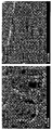
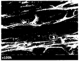
도 9는 실시예의 다공성 지지체의 표면 및 단면을 측정한 전자주사현미경 사진이다.
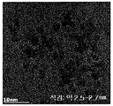
도 10은 실시예의 다공성 지지체에 코팅되는 백금 입자의 모양을 측정한 투과전자현미경 사진이다.
도 11은 실시예 및 비교예의 다공성 지지체 상에 놓여진 물과 디아이오도메탄(diiodomethane) 액적의 접촉각 측정을 통해 각각의 표면에너지를 계산한 결과를 나타낸 것이다.
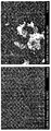
도 12는 비교예 3의 다공성 지지체의 표면을 측정한 전자주사현미경 사진이다.
도 13은 비교예 3의 다공성 지지체의 표면을 측정한 광학현미경 사진이다.
도 14는 비교예 3의 다공성 지지체의 단면을 측정한 전자주사현미경 사진이다.
<부호의 설명>
10: 전해질막
20, 21: 촉매층
40, 41: 기체확산층
50: 캐소드
51: 애노드
60: 스택
70: 산화제 공급부
80: 연료 공급부
81: 연료 탱크
82: 펌프
이하에서 본 명세서에 대하여 상세히 설명한다.
본 명세서는 다공성 고분자 지지체; 상기 다공성 고분자 지지체의 표면에 구비된 백금층 및 상기 다공성 고분자 지지체의 기공 내에 구비된 이온 전도성 고분자를 포함하는 강화막을 제공한다.
본 명세서는 다공성 고분자 지지체; 상기 다공성 고분자 지지체의 양면 및 기공 내의 표면에 분산된 백금 나노 입자; 및 상기 다공성 고분자 지지체의 기공 내에 구비된 이온 전도성 고분자를 포함하며, 상기 백금 나노 입자의 평균직경은 1nm 이상 50nm 이하인 것인 강화막을 제공한다.
상기 다공성 고분자 지지체는 다수의 기공이 구비되어 있다면 다공성 지지체의 구조 및 재질은 특별히 한정되지 않으며, 당 기술분야에서 일반적으로 사용하는 것을 이용할 수 있다. 예를 들면, 상기 다공성 고분자 지지체는 폴리 이미드(Polyimide:PI), 나일론, 폴리에틸렌테레프탈레이트(Polyethyleneterephtalate:PET), 폴리테트라플루오로 에틸렌(polytetrafluoro ethylene:PTFE), 폴리에틸렌(Polyethylene:PE), 폴리프로필렌(polypropylene:PP), 폴리아릴렌에테르 술폰(Poly(arylene ether sulfone):PAES) 및 폴리에테르에테르케톤(Polyetheretherketone:PEEK) 중 적어도 하나를 포함할 수 있다. 상기 다공성 고분자 지지체는 폴리올레핀계 고분자를 포함할 수 있으며, 구체적으로, 상기 다공성 고분자 지지체는 폴리에틸렌, 폴리프로필렌 및 폴리이소부틸렌 중 적어도 하나를 포함하는 폴리올레핀계 고분자를 포함할 수 있다.
상기 다공성 고분자 지지체의 기공의 개별직경은 1nm 이상 50㎛ 이하일 수 있다. 구체적으로, 상기 다공성 고분자 지지체의 기공의 개별직경은 10nm 이상 1㎛ 이하일 수 있으며, 바람직하게, 상기 다공성 고분자 지지체의 기공의 개별직경은 50 nm 이상 500nm 이하일 수 있다. 직경이 큰 기공이 있는 것보다 촘촘한 기공이 많을수록 통기도와 내구성이 증가하는 장점이 있다.
상기 다공성 고분자 지지체의 기공의 개별직경을 측정하는 방법은 특별히 한정하지 않으며, 당 기술분야에서 사용되는 방법을 채용할 수 있으나, 예를 들면, 전자현미경을 통해 기공의 직경을 측정할 수 있다.
상기 다공성 고분자 지지체의 기공율은 50% 이상 95% 이하일 수 있다. 이 경우 다공성 고분자 지지체의 기공 내로 이온전도성 고분자를 함침했을 때 이온 채널이 잘 형성되는 장점이 있다.
상기 다공성 고분자 지지체의 두께는 특별히 한정하지 않으나, 1㎛ 이상 20㎛ 이하일 수 있다.
상기 백금층은 상기 다공성 고분자 지지체의 양면 및 기공 내의 표면에 구비된 백금 나노 입자를 포함할 수 있다. 강화막 내에 고르게 분산된 백금 나노 입자를 통해 전해질막의 자가가습 기능이 도입될 수 있다. 구체적으로, 강화막을 크로스오버(crossover)하는 수소와 산소를 강화막 내의 백금입자가 촉매로서 작용하여 물을 생성할 수 있다. 또한, 상기 백금층은 강화 기재 표면에너지 향상을 통해 강화기재에 대한 이온 전도성 고분자의 함침도를 증가시킬 수 있다.
상기 백금 나노 입자의 평균직경은 1nm 이상 50nm 이하일 수 있다. 이 경우 강화막 내에서 이온전달에 대한 저항성은 최소화하면서 최대의 촉매 활성을 갖는 크기일 수 있다.
상기 백금 나노 입자의 평균직경은 1nm 이상 30nm 이하일 수 있으며, 더 구체적으로 1nm 이상 10nm 이하일 수 있다.
상기 백금 나노 입자의 개별직경은 0nm 초과 100nm 이하일 수 있으며, 구체적으로 0nm 초과 50nm 이하일 수 있고, 더 구체적으로 0nm 초과 30nm 이하일 수 있다.
여기서, 직경은 전자현미경을 통해 측정된 이미지에서 백금 나노 입자의 표면 상의 한 점으로부터 다른 한 점까지 거리 중 가장 긴 거리를 의미한다.
상기 이온 전도성 고분자는 다공성 고분자 지지체의 기공 내에 구비될 수 있다. 구체적으로, 상기 이온 전도성 고분자는 백금층이 구비된 다공성 고분자 지지체의 기공 내에 구비될 수 있다.
상기 백금층이 다공성 고분자 지지체의 양면 및 기공 내에 분산된 백금 나노 입자를 포함하는 경우, 상기 이온 전도성 고분자는 다공성 고분자 지지체의 기공 내에 구비된 백금 나노 입자의 표면과, 백금 나노 입자와 백금 나노 입자의 사이 즉 백금 나노 입자가 구비되지 않은 다공성 고분자 지지체의 기공 내에 구비될 수 있다.
다공성 고분자 지지체는 미세한 기공이 형성되어 있기 때문에, 같은 재질로 기공이 없는 지지체보다 다공성 고분자 지지체의 표면의 표면에너지가 높아 다공성 고분자 지지체의 기공 내에 고르게 이온 전도성 고분자를 침투되지 않거나 반발력에 의해 다공성 고분자 지지체의 표면으로 나오는 디웨팅(dewetting)이 일어날 수 있다.
본 발명의 백금층이 구비된 다공성 고분자 지지체는 이온 전도성 고분자와의 친밀도(affinity)가 좋아 이온 전도성 고분자가 다공성 고분자 지지체의 기공 내에 고르게 함침될 수 있다.
상기 이온 전도성 고분자는 이온 교환을 할 수 있는 물질이라면 특별히 한정하지 않으며, 당 기술분야에서 일반적으로 사용하는 것을 이용할 수 있다.
상기 이온 전도성 고분자는 탄화수소계 고분자, 부분불소계 고분자 또는 불소계 고분자일 수 있다.
상기 탄화수소계 고분자는 플루오린기가 없는 탄화수소계 술폰화(sulfonated) 고분자일 수 있으며, 반대로 불소계 고분자는 플루오린기로 포화된 술폰화(sulfonated) 고분자일 수 있고, 상기 부분불소계 고분자는 플루오린기로 포화되지 않은 술폰화(sulfonated) 고분자일 수 있다.
상기 이온 전도성 고분자는 퍼플루오르술폰산계 고분자, 탄화수소계 고분자, 방향족 술폰계 고분자, 방향족 케톤계 고분자, 폴리벤즈이미다졸계 고분자, 폴리스티렌계 고분자, 폴리에스테르계 고분자, 폴리이미드계 고분자, 폴리비닐리덴 플루오라이드계 고분자, 폴리에테르술폰계 고분자, 폴리페닐렌설파이드계 고분자, 폴리페닐렌옥사이드계 고분자, 폴리포스파젠계 고분자, 폴리에틸렌나프탈레이트계 고분자, 폴리에스테르계 고분자, 도핑된 폴리벤즈이미다졸계 고분자, 폴리에테르케톤계 고분자, 폴리에테르에테르케톤계 고분자, 폴리페닐퀴녹살린계 고분자, 폴리술폰계 고분자, 폴리피롤계 고분자 및 폴리아닐린계 고분자로 이루어진 군에서 선택되는 하나 또는 둘 이상의 고분자일 수 있다. 상기 고분자는 술폰화(sulfonated)하여 사용될 수 있으며, 단일 공중합체, 교대 공중합체, 랜덤 공중합체, 블록 공중합체, 멀티블록 공중합체 또는 그라프트 공중합체일 수 있으나, 이에 한정되는 것은 아니다.
상기 이온 전도성 고분자는 양이온 전도성을 가지는 고분자일 수 있으며, 예를 들면, 퍼플루오르술폰산계 고분자, 술폰화 폴리에테르에테르케톤 (sPEEK, Sulfonated Polyetheretherketone), 술폰화 폴리에테르케톤 (sPEK, sulfonated (polyetherketone)), 폴리비닐리덴 플로라이드-그라프트-폴리스티렌 술폰산 (poly (vinylidene fluoride)-graft-poly(styrene sulfonic acid), PVDF-g-PSSA) 및 술폰화 폴리플루로레닐 에테르케톤 (Sulfonated poly (fluorenyl ether ketone)) 중 적어도 하나를 포함할 수 있다.
상기 강화막의 총 중량을 기준으로, 상기 다공성 고분자 지지체의 함량은 5 중량% 이상 50중량% 이하일 수 있다.
상기 강화막의 총 중량을 기준으로, 상기 백금층의 함량은 0.1중량% 이상 10중량% 이하일 수 있다. 이 경우 강화막 내에서 이온전달에 대한 저항성은 최소화하면서 최대 자가가습 및 디웨팅 억제능을 갖는 크기일 수 있다.
상기 강화막의 총 중량을 기준으로, 상기 이온 전도성 고분자의 함량은 45중량% 이상 90중량% 이하일 수 있으며, 구체적으로, 45중량% 이상 90중량% 이하일 수 있고, 바람직하게는 50중량% 이상 90중량% 이하일 수 있다.
본 명세서는 애노드; 캐소드; 및 상기 애노드와 캐소드 사이에 구비된 상기 강화막을 포함하는 전기화학 전지를 제공한다.
상기 캐소드는 방전될 때 전자를 받아 환원되는 전극을 의미하고, 충전될 때 산화되어 전자를 내보내는 애노드(산화전극)일 수 있다. 상기 애노드는 방전될 때 산화되어 전자를 내보내는 전극을 의미하고, 충전될 때 전자를 받아 환원되는 캐소드(환원전극)일 수 있다.
상기 전기화학 전지는 화학반응을 이용한 전지를 의미하며 고분자 전해질막이 구비된다면 그 종류를 특별히 한정하지 않으나, 예를 들면, 상기 전기화학 전지는 연료전지, 금속 이차 전지 또는 흐름전지일 수 있다.
본 명세서는 전기화학 전지를 단위전지로 포함하는 것인 전기화학 전지모듈을 제공한다.
상기 전기화학 전지 모듈은 본 출원의 하나의 실시 상태에 따른 단위 전지 사이에 바이폴라(bipolar) 플레이트를 삽입하여 스택킹(stacking)하여 형성될 수 있다.
상기 전지 모듈은 구체적으로 전기자동차, 하이브리드 전기자동차, 플러그-인 하이브리드 전기자동차 또는 전력저장장치의 전원으로 사용될 수 있다.
본 명세서는 애노드, 캐소드 및 상기 애노드 및 캐소드 사이에 구비된 상기 강화막을 포함하는 것인 막 전극 접합체를 제공한다.
본 명세서는 상기 막 전극 접합체를 포함하는 연료 전지를 제공한다.
도 1은 연료전지의 전기 발생 원리를 개략적으로 도시한 것으로, 연료전지에 있어서, 전기를 발생시키는 가장 기본적인 단위는 막 전극 접합체(MEA)인데, 이는 전해질막(M)과 이 전해질막(M)의 양면에 형성되는 애노드(A) 및 캐소드(C)로 구성된다. 연료전지의 전기 발생 원리를 나타낸 도 1을 참조하면, 애노드(A)에서는 수소 또는 메탄올, 부탄과 같은 탄화수소 등의 연료(F)의 산화 반응이 일어나 수소 이온(H+) 및 전자(e-)가 발생하고, 수소 이온은 전해질막(M)을 통해 캐소드(C)으로 이동한다. 캐소드(C)에서는 전해질막(M)을 통해 전달된 수소 이온과, 산소와 같은 산화제(O) 및 전자가 반응하여 물(W)이 생성된다. 이러한 반응에 의해 외부회로에 전자의 이동이 발생하게 된다.
도 2는 연료전지용 막 전극 접합체의 구조를 개략적으로 도시한 것으로, 연료전지용 막 전극 접합체는 전해질막(10)과, 이 전해질막(10)을 사이에 두고 서로 대향하여 위치하는 캐소드(50) 및 애노드(51)를 구비할 수 있다. 상기 캐소드에는 전해질막(10)으로부터 순차적으로 캐소드 촉매층(20)과 캐소드 기체확산층(40)이 구비되고, 상기 애노드에는 전해질막(10)으로부터 순차적으로 애노드 촉매층(21) 및 애노드 기체확산층(41)이 구비될 수 있다.
도 3은 연료전지의 구조를 개략적으로 도시한 것으로, 연료전지는 스택(60), 산화제 공급부(70) 및 연료 공급부(80)를 포함하여 이루어진다.
스택(60)은 상술한 막 전극 접합체를 하나 또는 둘 이상 포함하며, 막 전극 접합체가 둘 이상 포함되는 경우에는 이들 사이에 개재되는 세퍼레이터를 포함한다. 세퍼레이터는 막 전극 접합체들이 전기적으로 연결되는 것을 막고 외부에서 공급된 연료 및 산화제를 막 전극 접합체로 전달하는 역할을 한다.
산화제 공급부(70)는 산화제를 스택(60)으로 공급하는 역할을 한다. 산화제로는 산소가 대표적으로 사용되며, 산소 또는 공기를 산화제 공급부(70)로 주입하여 사용할 수 있다.
연료 공급부(80)는 연료를 스택(60)으로 공급하는 역할을 하며, 연료를 저장하는 연료탱크(81) 및 연료탱크(81)에 저장된 연료를 스택(60)으로 공급하는 펌프(82)로 구성될 수 있다. 연료로는 기체 또는 액체 상태의 수소 또는 탄화수소 연료가 사용될 수 있다. 탄화수소 연료의 예로는 메탄올, 에탄올, 프로판올, 부탄올 또는 천연가스를 들 수 있다.
본 명세서는 다공성 고분자 지지체의 표면에 백금층을 형성하는 단계; 및 상기 백금층이 표면에 구비된 다공성 고분자 지지체의 기공 내에 이온 전도성 고분자를 형성하는 단계를 포함하는 것인 강화막의 제조방법을 제공한다.
상기 강화막의 제조방법은 강화막에 대하여 상술한 바를 인용할 수 있다.
상기 강화막의 제조방법은 다공성 고분자 지지체의 표면에 백금층을 형성하는 단계를 포함할 수 있다.
상기 백금층을 형성하는 단계는 다공성 고분자 지지체를 백금 나노 입자의 전구체를 포함하는 제1 용액에 함침하는 단계를 포함할 수 있다. 상기 백금 나노 입자는 백금 원소를 함유한 나노 입자를 의미하며, 백금 나노 입자의 전구체는 백금원소를 포함하는 전구체 중 적어도 하나를 포함할 수 있다. 여기서, 전구체는 화학적 반응에서 특정 물질이 되기 전 단계의 물질을 의미하며, 구체적으로 백금금속의 전 단계의 물질을 의미한다.
상기 제1 용액은 용매, 분산제 및 환원제 중 적어도 하나를 더 포함할 수 있다.
상기 백금 나노 입자의 전구체의 함량은 다공성 고분자 지지체의 중량의 0.01중량% 이상 10중량% 이하일 수 있으며, 구체적으로 다공성 고분자 지지체의 중량의 0.01중량% 이상 5중량% 이하일 수 있다.
상기 제1 용액의 총 중량을 기준으로, 상기 백금 나노 입자의 전구체의 함량은 0.01중량% 이상 10중량% 이하일 수 있다.
상기 제1 용액의 총 중량을 기준으로, 상기 용매의 함량은 80중량% 이상 90중량% 이하일 수 있다.
상기 제1 용액의 총 중량을 기준으로, 상기 분산제의 함량은 0.01중량% 이상 10중량% 이하일 수 있다.
상기 백금층을 형성하는 단계는 제1 용액을 가열하는 단계를 더 포함할 수 있으며, 이 경우 최종온도는 30℃ 이상 100℃ 이하일 수 있다.
상기 백금층을 형성하는 단계는 다공성 고분자 지지체를 준비하는 단계; 다공성 고분자 지지체를 백금 나노 입자의 전구체를 포함하는 제1 용액에 함침하는 단계; 상기 백금 나노 입자의 전구체를 환원시키는 단계; 및 다공성 고분자 지지체를 건조하는 단계를 포함할 수 있다.
상기 다공성 고분자 지지체를 준비하는 단계는 상기 다공성 고분자 지지체를 제조하거나, 제조된 다공성 고분자 지지체를 구입하여 준비하는 단계일 수 있다.
상기 다공성 고분자 지지체에 제1 용액을 함침하기 전에 다공성 고분자 지지체의 내부 표면을 전처리하는 단계를 더 포함할 수 있다.
상기 다공성 고분자 지지체의 전처리 단계는 다공성 고분자 지지체를 전처리 용매에 함침하는 단계를 포함할 수 있다.
상기 전처리 용매는 특별히 한정하지 않으나, 메탄올, 에탄올 등의 알코올 계 용매 및 에틸렌글리콜과 같은 폴리올계 용매 중 적어도 하나를 포함할 수 있다.
상기 백금 나노 입자의 전구체를 환원시키는 단계는 환원제를 첨가하여 백금 나노 입자의 전구체를 백금 나노 입자로 환원시킬 수 있다. 이때, 사용되는 환원제는 특별히 한정하지 않으나, 예를 들면 NaBH4, NH2NH2, LiAlH4 및 LiBEt3H로 이루어진 군에서 선택되는 하나 또는 둘 이상일 수 있다.
상기 강화막의 제조방법은 상기 백금층이 표면에 구비된 다공성 고분자 지지체의 기공 내에 이온 전도성 고분자를 형성하는 단계를 포함할 수 있다.
상기 이온 전도성 고분자를 형성하는 단계는 상기 백금층이 표면에 구비된 다공성 고분자 지지체를 이온 전도성 고분자를 포함하는 제2 용액에 함침하는 단계를 포함할 수 있다.
상기 다공성 고분자 지지체에 용액을 함침하는 방법은 특별히 한정하지 않으며, 다공성 고분자 지지체를 용액이 담긴 욕조에 넣거나, 다공성 고분자 지지체의 일면 또는 양면에 용액을 도포한 후 다공성 고분자 지지체의 기공 내로 용액이 침투하도록 가압할 수 있다.
상기 제2 용액은 용매를 더 포함할 수 있다.
상기 제2 용액의 총 중량을 기준으로, 상기 이온 전도성 고분자의 함량은 1중량% 이상 20중량% 이하일 수 있다.
상기 제2 용액의 총 중량을 기준으로, 상기 용매의 함량은 80중량% 이상 99중량% 이하일 수 있다.
상기 제2 용액의 점도는 이온전도성 고분자의 종류, 분자량, 농도, 그리고 용매의 종류에 따라 조절될 수 있으며, 예를 들면, 10cP 이상 500cP 이하일 수 있다. 이 경우 연료 등에 대한 일정 이상의 크로스오버율을 유지하면서, 최대의 이온의 전도성을 가질 수 있다.
이하에서, 실시예를 통하여 본 명세서를 더욱 상세하게 설명한다. 그러나, 이하의 실시예는 본 명세서를 예시하기 위한 것일 뿐, 본 명세서를 한정하기 위한 것은 아니다.
[실시예]
[실시예 1]
1) 탄화수소계 고분자의 제조
딘스탁트랩(Dean-Stark trap)과 콘덴서가 장착된 1L 둥근 바닥 플라스크에 히드로퀴논술폰산 포타슘염(hydroquinonesulfonic acid potassium salt) (0.9eq.), 4,4'-디플루오로벤조페논(4,4'-difluorobenzophenone)(0.97eq.)과 3,5-비스(4-플루오로벤조일)페닐(4-플루오로페닐)메타논 (3,5-bis(4-fluorobenzoyl)phenyl(4-fluorophenyl)methanone)(0.02eq.)을 넣고 디메틸술폭시드(DMSO, dimethyl sulfoxide)와 벤젠 용매에서 탄산 칼륨(K2CO3, potassium carbonate)을 촉매로 사용하여 질소분위기 내에서 준비하였다. 그 다음 상기 반응 혼합물을 140℃의 온도로 오일 바트(oil bath)에서 4시간 동안 교반하여 벤젠이 역류하면서 딘-스탁 장치의 분자체(molecular sieves)에 공비혼합물을 흡착시켜 제거한 후, 반응온도를 180℃로 승온시키고 20시간 동안 축중합 반응시켰다. 상기 반응종료 후 상기 반응물의 온도를 60℃로 감온시킨 후, 동일 플라스크에 4,4'-디플루오로벤조페논(4,4'-Difluorobenzophenone)(0.2275eq.), 9,9-비스(히드록시페닐)플루오린 (9,9-bis(hydroxyphenyl)fluorine)(0.335eq.)과 3,5-비스(4- 플루오로벤조일)페닐(4- 플루오로페닐)-메타논 (3,5-bis(4-fluorobenzoyl)phenyl(4-fluorophenyl)-methanone)(0.005eq.)을 넣고 DMSO와 벤젠을 이용하여 질소분위기에서 K2CO3를 촉매로 사용하여 반응을 다시 개시하였다.
그 다음 상기 반응 혼합물을 다시 140℃의 온도로 오일 바트(oil bath)에서 4시간 동안 교반하여 벤젠이 역류하면서 딘-스탁 장치의 분자체(molecular sieves)에 공비혼합물을 흡착시켜 제거한 후, 반응온도를 180℃로 승온시키고 20시간 동안 축중합 반응시켰다. 그 다음 반응물의 온도를 실온으로 감온시키고 DMSO를 더 가하여 생성물을 희석시킨 후, 희석된 생성물을 과량의 메탄올에 부어 용매로부터 공중합체를 분리하였다. 그 후, 물을 이용하여 과량의 탄산 칼륨(potassium carbonate)을 제거한 뒤, 여과하여 얻은 공중합체를 80℃의 진공오븐에서 12시간 이상 건조하여 소수 블록과 친수 블록이 교대로 화학결합으로 이어진 브렌치된 술폰화 멀티 블록 공중합체(이하, 탄화수소계 고분자)를 제조하였다.
2) 다공성 지지체에 대한 백금 입자 처리
백금 입자는 백금 전구체(H2PtCl6)의 환원 반응을 통하여 제조하였으며, 다공성 지지체에 대한 코팅방법은 다음과 같다. 백금 전구체 (다공성 지지체 대비 1wt%)와 분산제 (백금 전구체와 동일 몰 중량)를 에탄올과 물로 이루어진 이성분 용매에 녹이고 40℃로 가열하며 교반시켜 백금 전구체 용액을 제조했다. 두께 약 7㎛, 기공도 약 75%의 3차원 망상 구조를 가진 폴리프로필렌 지지체를 에탄올로 전처리한 뒤, 백금 전구체 용액에 담지했다. 마지막으로, 환원제 (NaBH4)를 첨가하여 백금 전구체를 백금 금속 입자로 환원시켰다. 환원 과정에서 용액의 색상이 검게 변하였으며, 이를 통해 백금 전구체가 입자로 환원되는 것을 확인할 수 있다. 6시간 이상의 충분한 시간 동안 반응을 거친 후, 백금입자가 코팅된 다공성 지지체는 증류수로 세척한 후, 고온에서 건조하여 보관하였다.
3) 강화막 제조
디메틸설폭사이드(DMSO) 용매에 1)에서 합성된 탄화수소계 고분자를 녹여 전도성 고분자 조성물을 제작하였다. 백금입자가 코팅된 지지체 양면에 고분자 용액을 함침시켜 코팅하고, 80℃ 오븐에서 24시간 동안 건조하여 탄화수소계 강화막을 제조하였다. 제조된 강화막은 10% 황산으로 80℃에서 24시간 산처리 후, 증류수로 4회 이상 세척한 뒤, 80℃에서 건조하여 강화막을 제조하였다.
[비교예 1]
다공성 지지체를 백금 입자로 코팅되지 않은 것을 제외하고는 실시예1과 동일한 방법으로 강화막을 제조하였다.
[비교예 2]
다공성 지지체를 백금 입자로 전처리하는 2) 단계 없이, 실시예 1의 전도성 고분자 조성물에 백금 입자와 분산제를 추가로 첨가하여 함침 용액을 제조하였으며, 실시예와 동일한 방법으로 강화막을 제조하였다.
[비교예 3]
Pt 나노입자(평균입경 7nm, 제조사 Alfa Aesar)를 물과 에탄올 (50:50 부피비) 이종용매에 분산하여 용액을 제조했으며, 다공성 지지체에 스프레이 코팅했다. 이때, 코팅된 Pt 나노입자의 중량은 다공성 지지체 대비 1 wt%이었다.
[실험예 1]
상기 실시예 및 비교예에 따라 제조된 강화막의 연료전지에서의 성능을 측정하기 위하여, 상기 강화막을 포함하는 막전극 접합체를 제조하였다. 구체적으로, 상기 강화막을 7 cm × 7 cm 의 사각형으로 절취하고, 상기 고분자 전해질막의 상면 및 하면에 백금 0.4 mg/cm2의 카본담지 백금촉매를 5 cm × 5 cm 크기로 전사하여 막 전극 접합체를 제조하였다.
상기 제조된 막 전극 접합체의 성능평가는 H2/Air 및 상압 조건에서 상대습도 (RH) 100%, 50% 및 32 % 조건에서 각각 실시하였다.
도 5는 상대습도 (RH) 100% 조건에서의 실시예 및 비교예에 따른 막 전극 접합체의 전류밀도에 따른 전압을 나타낸 것이다.
도 6은 상대습도 (RH) 50% 조건에서의 실시예 및 비교예에 따른 강화막의 연료전지에서의 전류밀도에 따른 전압을 나타낸 것이다.
도 7은 상대습도 (RH) 32% 조건에서의 실시예 및 비교예에 따른 막 전극 접합체의 전류밀도에 따른 전압을 나타낸 것이다.
도 8은 상대습도 (RH) 50%와 32 % 조건에서의 실시예 및 비교예에 따른 막 전극 접합체의 0.6 V에서의 전류밀도 값을 나타낸 것이다.
상기 도 5 내지 도 8의 결과에서 알 수 있듯이, 실시예에 따른 강화막과 같이 백금 입자가 다공성 지지체에 코팅되어 고르게 분산되어 있는 경우 저 가습 조건에서 더욱 안정적이고, 우수한 성능을 유지할 수 있다.
[실험예 2]
실시예 1에 따른 다공성 지지체에 코팅된 백금 입자의 크기, 모양, 분산도를 전자주사현미경(SEM, scanning electron microscopy) 및 투과전자현미경(TEM, tunneling electron microscopy)을 이용하여 측정하였으며, 그 결과를 도 9 내지 도 10에 도시하였다.
또한, 비교예 3에 따른 백금 입자로 표면처리된 다공성 지지체의 표면 및 단면을 전자주사현미경(SEM, scanning electron microscopy)과 광학현미경으로 측정하였으며, 그 결과를 도 12 내지 도 14에 도시하였다.
도 12를 통해 표면에 백금 입자가 뭉쳐져 있는 것을 확인할 수 있으며, 도 13을 통해 스프레이로 뿌려진 용매가 마른 자국을 따라 백금 입자가 뭉쳐져 있음을 확인할 수 있다.
도 14를 통해, 비교예 3에 따른 다공성 지지체의 단면으로서, 다공성 지지체의 내부 즉 기공 내에는 백금 입자가 거의 발견되지 않았으며, 관찰되더라도 표시된 부분과 같이 클러스터 형태로 백금 입자가 뭉쳐져 있는 것을 확인할 수 있었다.
[실험예 3]
접촉각 측정 장치를 이용하여 실시예와 비교예에 따른 다공성 지지체 상에 놓여진 물과 디아이오도메탄(diiodomethane) 액적(droplet)의 접촉각 측정을 통해 각각의 표면에너지를 계산하였으며, 그 결과를 도 11에 나타냈다.
상기 도 11의 결과에서 알 수 있듯이, 실시예에 따른 다공성 지지체와 같이 백금 입자가 다공성 지지체 내에 코팅되어 있을 경우, 표면에너지가 증가하고 이를 통해 이온전도성 고분자 함침 시 발생할 수 있는 디웨팅 현상을 억제할 수 있다.
또한, 비교예 3에서 육안상 백금 입자가 잘 보이지 않는 부분은 비교예 1과 같이 표면에너지가 거의 변화 없으나, 백금 입자가 뭉쳐져 코팅되어 있는 부분은 실시예와 같이 표면에너지가 증가한다. 그러나, 이러한 불균일 코팅은 연료전지의 저항을 증가시킬 수 있다.
[실험예 4]
실시예 1 내지 2 및 비교예 1 내지 2에서 제조된 다공성 지지체의 표면 및 측면을 무작위 위치에서 선택하여 5곳을 50000배 배율로 SEM을 측정하고, 이에 나타난 백금 나노입자의 개수 및 크기를 측정하여 평균했다.
| 개별직경범위(nm) | 평균직경(nm) | |
| 실시예 1 | 4 ~ 37 | 16 |
| 비교예 1 | 백금입자 없음 | 백금입자 없음 |
| 비교예 2 | 고분자 함침 후 확인 어려움 | 고분자 함침 후 확인 어려움 |
| 비교예 3 | 10 ~ 1200 | 360 |
비교예 1은 백금입자를 포함하지 않은 강화막이며, 비교예 2는 백금 나노입자를 전도성 고분자에 분산한 뒤, 이를 지지체에 코팅하였기 때문에 지지체에 코팅된 백금 나노 입자를 SEM으로 정확히 확인하기 어려웠다.
Claims (9)
- 다공성 고분자 지지체;상기 다공성 고분자 지지체의 양면 및 기공 내의 표면에 분산된 백금 나노 입자; 및상기 다공성 고분자 지지체의 기공 내에 구비된 이온 전도성 고분자를 포함하며,상기 백금 나노 입자의 평균직경은 1nm 이상 50nm 이하인 것인 강화막.
- 청구항 1에 있어서, 상기 다공성 고분자 지지체는 폴리올레핀계 고분자를 포함하는 것인 강화막.
- 청구항 1에 있어서, 상기 다공성 고분자 지지체의 기공율은 50% 이상 95% 이하인 것인 강화막.
- 청구항 1에 있어서, 상기 강화막의 총 중량을 기준으로, 상기 백금 나노 입자의 함량은 0.1중량% 이상 10중량% 이하인 것인 강화막.
- 애노드; 캐소드; 및 상기 애노드와 캐소드 사이에 구비된 청구항 1 내지 4 중 어느 한 항에 따른 강화막을 포함하는 전기화학 전지.
- 애노드; 캐소드; 및 상기 애노드와 캐소드 사이에 구비된 청구항 1 내지 4 중 어느 한 항에 따른 강화막을 포함하는 막 전극 접합체.
- 청구항 6의 막 전극 접합체를 포함하는 연료 전지.
- 다공성 고분자 지지체를 백금 나노 입자의 전구체를 포함하는 용액에 함침하여, 상기 다공성 고분자 지지체의 양면 및 기공 내의 표면에 분산된 백금 나노 입자를 형성하는 단계; 및상기 백금 나노 입자가 표면에 구비된 다공성 고분자 지지체의 기공 내에 이온 전도성 고분자를 형성하는 단계를 포함하며,상기 백금 나노 입자의 평균직경은 1nm 이상 50nm 이하인 것인 강화막의 제조방법.
- 청구항 8에 있어서, 상기 이온 전도성 고분자를 형성하는 단계는 상기 백금 나노 입자가 양면 및 기공 내의 표면에 분산된 다공성 고분자 지지체를 이온 전도성 고분자를 포함하는 용액에 함침하는 단계를 포함하는 것인 강화막의 제조방법.
Priority Applications (2)
| Application Number | Priority Date | Filing Date | Title |
|---|---|---|---|
| US15/777,997 US10476094B2 (en) | 2016-03-31 | 2017-03-31 | Reinforced membrane, electrochemical cell and fuel cell comprising same, and production method for reinforced membrane |
| CN201780004685.9A CN108475801A (zh) | 2016-03-31 | 2017-03-31 | 增强膜、包括所述增强膜的电化学电池和燃料电池、以及所述增强膜的制备方法 |
Applications Claiming Priority (2)
| Application Number | Priority Date | Filing Date | Title |
|---|---|---|---|
| KR10-2016-0039723 | 2016-03-31 | ||
| KR20160039723 | 2016-03-31 |
Publications (1)
| Publication Number | Publication Date |
|---|---|
| WO2017171471A1 true WO2017171471A1 (ko) | 2017-10-05 |
Family
ID=59966162
Family Applications (1)
| Application Number | Title | Priority Date | Filing Date |
|---|---|---|---|
| PCT/KR2017/003553 Ceased WO2017171471A1 (ko) | 2016-03-31 | 2017-03-31 | 강화막, 이를 포함하는 전기화학 전지 및 연료 전지, 및 상기 강화막의 제조방법 |
Country Status (4)
| Country | Link |
|---|---|
| US (1) | US10476094B2 (ko) |
| KR (1) | KR20170113431A (ko) |
| CN (1) | CN108475801A (ko) |
| WO (1) | WO2017171471A1 (ko) |
Families Citing this family (5)
| Publication number | Priority date | Publication date | Assignee | Title |
|---|---|---|---|---|
| KR102446619B1 (ko) | 2019-03-19 | 2022-09-22 | 주식회사 엘지에너지솔루션 | 전고체 전지용 전해질막 및 이를 제조하는 방법 |
| KR102869192B1 (ko) | 2019-09-05 | 2025-10-10 | 현대자동차주식회사 | 연료전지용 고분자 전해질막 및 그 제조방법 |
| KR20210132342A (ko) * | 2020-04-27 | 2021-11-04 | 현대자동차주식회사 | 막-전극 접합체용 전극 및 이의 제조방법 |
| GB202214254D0 (en) | 2022-09-29 | 2022-11-16 | Johnson Matthey Plc | Process and membrane |
| GB2638432A (en) | 2024-02-22 | 2025-08-27 | Johnson Matthey Hydrogen Technologies Ltd | Process and membrane |
Citations (5)
| Publication number | Priority date | Publication date | Assignee | Title |
|---|---|---|---|---|
| KR20010092913A (ko) * | 2000-03-27 | 2001-10-27 | 윤종용 | 강화제가 부가된 복합 이온 전도성 고분자막 및 이를채용하고 있는 연료전지 |
| KR20120136442A (ko) * | 2011-06-09 | 2012-12-20 | 고려대학교 산학협력단 | 탄소나노튜브 담지 백금 촉매의 제조방법, 이에 의하여 제조된 촉매 및 이를 포함하는 양성자 교환막 연료전지 |
| US20130052563A1 (en) * | 2010-02-26 | 2013-02-28 | Johnson Matthey Public Limited Company | Membrane |
| KR101464317B1 (ko) * | 2014-03-21 | 2014-11-26 | (주)유니암 | 다공성 탄소 구조체 및 이를 포함하는 연료전지 |
| KR20150060435A (ko) * | 2013-11-26 | 2015-06-03 | 건국대학교 산학협력단 | 연료전지용 복합 분리막 및 이의 제조방법 |
Family Cites Families (5)
| Publication number | Priority date | Publication date | Assignee | Title |
|---|---|---|---|---|
| US6562446B1 (en) * | 1998-08-05 | 2003-05-13 | Japan Storage Battery Co., Ltd. | Multi-layer polymer electrolyte-membrane, electrochemical apparatus and process for the preparation of multi-layer polymer electrolyte membrane |
| US20060177720A1 (en) | 2001-08-20 | 2006-08-10 | Hae-Kyoung Kim | Reinforced composite ionic conductive polymer membrane, fuel cell adopting the same, and method of making the same |
| US9346673B2 (en) * | 2004-06-23 | 2016-05-24 | Samsung Sdi Co., Ltd. | Electrode for fuel cell, membrane-electrode assembly for fuel cell comprising the same, fuel cell system comprising the same, and method for preparing the electrode |
| JP2007048471A (ja) | 2005-08-05 | 2007-02-22 | Toyota Motor Corp | 燃料電池用補強型電解質膜、その製造方法、及び燃料電池用膜−電極接合体 |
| CN104247118B (zh) * | 2012-03-29 | 2016-10-26 | 可隆工业株式会社 | 聚合物电解质膜及其制造方法以及包含该聚合物电解质膜的膜电极组件 |
-
2017
- 2017-03-31 US US15/777,997 patent/US10476094B2/en active Active
- 2017-03-31 CN CN201780004685.9A patent/CN108475801A/zh active Pending
- 2017-03-31 WO PCT/KR2017/003553 patent/WO2017171471A1/ko not_active Ceased
- 2017-03-31 KR KR1020170041451A patent/KR20170113431A/ko not_active Ceased
Patent Citations (5)
| Publication number | Priority date | Publication date | Assignee | Title |
|---|---|---|---|---|
| KR20010092913A (ko) * | 2000-03-27 | 2001-10-27 | 윤종용 | 강화제가 부가된 복합 이온 전도성 고분자막 및 이를채용하고 있는 연료전지 |
| US20130052563A1 (en) * | 2010-02-26 | 2013-02-28 | Johnson Matthey Public Limited Company | Membrane |
| KR20120136442A (ko) * | 2011-06-09 | 2012-12-20 | 고려대학교 산학협력단 | 탄소나노튜브 담지 백금 촉매의 제조방법, 이에 의하여 제조된 촉매 및 이를 포함하는 양성자 교환막 연료전지 |
| KR20150060435A (ko) * | 2013-11-26 | 2015-06-03 | 건국대학교 산학협력단 | 연료전지용 복합 분리막 및 이의 제조방법 |
| KR101464317B1 (ko) * | 2014-03-21 | 2014-11-26 | (주)유니암 | 다공성 탄소 구조체 및 이를 포함하는 연료전지 |
Also Published As
| Publication number | Publication date |
|---|---|
| CN108475801A (zh) | 2018-08-31 |
| US20180351190A1 (en) | 2018-12-06 |
| KR20170113431A (ko) | 2017-10-12 |
| US10476094B2 (en) | 2019-11-12 |
Similar Documents
| Publication | Publication Date | Title |
|---|---|---|
| WO2014104785A1 (en) | Reinforced composite membrane for fuel cell and membrane-electrode assembly for fuel cell comprising the same | |
| WO2017171471A1 (ko) | 강화막, 이를 포함하는 전기화학 전지 및 연료 전지, 및 상기 강화막의 제조방법 | |
| US20110097651A1 (en) | Membrane Electrode Assembly (MEA) Fabrication Procedure on Polymer Electrolyte Membrane Fuel Cell | |
| WO2017052248A1 (ko) | 연료 전지용 막-전극 어셈블리, 이의 제조 방법, 그리고 이를 포함하는 연료 전지 시스템 | |
| WO2019004711A1 (ko) | 탄소 나노 섬유 방사층을 포함하는 연료전지용 기체확산층 | |
| CN101350408A (zh) | 燃料电池的膜电极组件及其制备方法以及包含它的燃料电池 | |
| WO2020111687A1 (ko) | 레독스 흐름 전지용 분리막 및 이의 제조방법 | |
| WO2020138800A1 (ko) | 촉매, 이의 제조 방법, 이를 포함하는 전극, 이를 포함하는 막-전극 어셈블리, 및 이를 포함하는 연료 전지 | |
| KR101041125B1 (ko) | 연료 전지용 전극, 연료 전지용 막-전극 어셈블리, 및 이를포함하는 연료 전지 시스템 | |
| KR20130110569A (ko) | 고분자 전해질막 및 그 제조방법 | |
| KR100637169B1 (ko) | 복합전해질막 | |
| WO2016117915A1 (ko) | 고분자 전해질 막 및 그 제조방법 | |
| CN1903919A (zh) | 燃料电池用的聚合物电解质,其生产方法,及含其的燃料电池系 | |
| WO2022071684A1 (ko) | 고분자 전해질막, 이를 포함하는 막-전극 어셈블리 및 연료 전지 | |
| KR20170136372A (ko) | 강화막, 이를 포함하는 막 전극 접합체 및 연료 전지, 및 이의 제조방법 | |
| WO2019143097A1 (ko) | 막 전극 접합체의 제조방법 및 적층체 | |
| WO2024014741A1 (ko) | 고분자 전해질막 및 이를 포함하는 막-전극 어셈블리 | |
| KR102706751B1 (ko) | 전해질 막의 제조방법 | |
| WO2023101266A1 (ko) | 고분자 전해질막, 이의 제조 방법 및 이를 포함하는 전기 화학 장치 | |
| KR20080048352A (ko) | 분산성이 개선된 고분자 전해질 연료전지용 전극, 이를포함하는 고분자 전해질 연료전지 및 그 제조방법 | |
| KR102090860B1 (ko) | 고분자 전해질막, 이를 포함하는 막 전극 접합체 및 상기 막 전극 접합체를 포함하는 연료 전지 | |
| WO2023113218A1 (ko) | 고분자 전해질막, 이의 제조 방법 및 이를 포함하는 막-전극 어셈블리 | |
| WO2023018126A1 (ko) | 비백금 촉매 및 그래핀 적층구조를 포함하는 연료전지용 전극 및 이를 포함하는 막-전극 접합체 | |
| WO2017039340A1 (ko) | 복합 전해질막, 강화복합 전해질막 및 이를 포함하는 연료전지 | |
| WO2023177076A1 (ko) | 고분자 전해질막의 제조 방법 |
Legal Events
| Date | Code | Title | Description |
|---|---|---|---|
| NENP | Non-entry into the national phase |
Ref country code: DE |
|
| 121 | Ep: the epo has been informed by wipo that ep was designated in this application |
Ref document number: 17775895 Country of ref document: EP Kind code of ref document: A1 |
|
| 122 | Ep: pct application non-entry in european phase |
Ref document number: 17775895 Country of ref document: EP Kind code of ref document: A1 |