WO2017174157A1 - Sèche-linge doté d'une porte à facilité d'utilisation améliorée - Google Patents
Sèche-linge doté d'une porte à facilité d'utilisation améliorée Download PDFInfo
- Publication number
- WO2017174157A1 WO2017174157A1 PCT/EP2016/057811 EP2016057811W WO2017174157A1 WO 2017174157 A1 WO2017174157 A1 WO 2017174157A1 EP 2016057811 W EP2016057811 W EP 2016057811W WO 2017174157 A1 WO2017174157 A1 WO 2017174157A1
- Authority
- WO
- WIPO (PCT)
- Prior art keywords
- door
- lever arm
- main body
- catch
- laundry dryer
- Prior art date
- Legal status (The legal status is an assumption and is not a legal conclusion. Google has not performed a legal analysis and makes no representation as to the accuracy of the status listed.)
- Ceased
Links
Images



Classifications
-
- D—TEXTILES; PAPER
- D06—TREATMENT OF TEXTILES OR THE LIKE; LAUNDERING; FLEXIBLE MATERIALS NOT OTHERWISE PROVIDED FOR
- D06F—LAUNDERING, DRYING, IRONING, PRESSING OR FOLDING TEXTILE ARTICLES
- D06F39/00—Details of washing machines not specific to a single type of machines covered by groups D06F9/00 - D06F27/00
- D06F39/12—Casings; Tubs
- D06F39/14—Doors or covers; Securing means therefor
-
- D—TEXTILES; PAPER
- D06—TREATMENT OF TEXTILES OR THE LIKE; LAUNDERING; FLEXIBLE MATERIALS NOT OTHERWISE PROVIDED FOR
- D06F—LAUNDERING, DRYING, IRONING, PRESSING OR FOLDING TEXTILE ARTICLES
- D06F58/00—Domestic laundry dryers
- D06F58/02—Domestic laundry dryers having dryer drums rotating about a horizontal axis
- D06F58/04—Details
Definitions
- the present invention relates to a laundry treatment appliance such as a laundry dryer or a laundry washer-and-dryer.
- the present invention more particularly relates to the door of the laundry treatment appliance.
- a laundry dryer generally comprises: a main body which comprises a drum for receiving the articles to be dried; an aperture for allowing the user to access the drum; a door for pivotably opening/closing the aperture; and a handle which is disposed onto the door.
- the laundry dryer is generally provided without a locking means, but with a fastening means for fastening the door to main body at the closed position so as to enable the user to open/close the door also during the operation. Thereby the risk to the safety of the user can be eliminated or reduced as much as possible.
- the fastening means generally comprises a latch and a catch which resiliently engage with or disengage from each other respectively when the door is pressed towards the closed position or pulled away from the closed position at least through a threshold force.
- This threshold force is prescribed by international standards for the household appliance manufacturers. The door must not open during the operation through the mechanical stress exerted by the agitated articles or the circulating process air inside the rotating drum. Therefore, this threshold force is determined in accordance with such requirements.
- US20040107598A1 discloses a laundry dryer which has a door that is provided with a fastening means as specified above.
- a problem with the prior art laundry dryers is that many user have difficulties in opening the door since they cannot easily overcome the predetermined threshold force, and thus the users cannot smoothly open the door.
- An objective of the present invention is to provide a laundry dryer having a door which overcomes the aforementioned problems of the prior art in a cost-effective way and which enables an improved production, assemblage and usability.
- the handle comprises a lever which includes a first lever arm that can be manipulated by the user and a second lever arm that is configured to be pressed onto the main body, and to push the door away from the main body when the first lever arm is manipulated by the user and/or configured to be pressed onto the catch and to disengage the catch from the latch when the first lever arm is manipulated by the user, wherein in the latter configuration the latch is disposed onto the door and the catch is disposed on the main body.
- the lever may be configure in three different ways.
- the term “laundry dryer” should not be understood in the narrow sense and may also refer to a laundry dryer having a laundry washing function as in the combined type laundry washer-and-dryer.
- a major advantageous effect of the present invention is that the door can be easily opened by virtue of the leverage, and thus the user can be relieved from applying the predetermined threshold force required for releasing the fastening means, and can be further enabled to open the door by applying a comparatively weaker force to the first lever arm.
- Another major advantageous effect of the present invention is that the laundry dryer can be prevented from becoming dislocated from its position on the floor to the front side as the door can be opened by the user by applying a comparatively weaker force.
- Another major advantageous effect of the present invention is that the laundry dryer has been rendered more user-friendly. Thereby, the user satisfaction can be further improved.
- a pusher is pivotably disposed onto the second lever arm.
- the pusher has a seating surface which is pressed onto the front surface of the main body (1a) so as to push the door away from the main body (1a) when the first lever arm is manipulated.
- This embodiment is particularly advantageous as the contact between the second lever arm and the main body (1a) can be improved during the opening of the door, and thus the door can be opened more smoothly.
- Figure 1 – is a schematic partial front view of the laundry dryer according to an embodiment of the present invention.
- Figure 2 – is a schematic rear view of the door of the laundry dryer in Fig. 1;
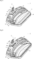
- Figure 3 – is a schematic perspective view of the handle of the door in Fig.1, wherein the first lever arm is in the released position;
- Figure 4 – is a schematic perspective view of the handle of the door in Fig.1, wherein the first lever arm is in the pulled position;
- Figure 5 – is a schematic partial sectional view of the frontal wall of the laundry dryer in Fig.1, taken along the line A-A, when the door is in the closed position, and wherein the first lever arm is in the released position;
- Figure 6 – is a schematic partial sectional view of the frontal wall of the laundry dryer in Fig.1, taken along the line A-A, when the door is in an opened position, and wherein the first lever arm is in the pulled position.
- the laundry dryer (1) comprises: a main body (1a) which comprises a drum for receiving the articles to be dried; and an aperture for allowing the user to access the drum (Fig. 1).
- the laundry dryer (1) further comprises a door (1b) for pivotably opening/closing the aperture, wherein the door (1b) is movable between an open position and a closed position; a handle (2) which is disposed onto the door (1b); and a fastening means (3) for fastening the door (1b) to the main body (1a) at the closed position (Fig. 5).
- the fastening means (3) has a latch (4) and a spring-loaded catch (4a) (the spring is not shown) which resiliently engage with or disengage from each other respectively when the door (1b) is pressed towards the closed position or pulled away from the closed position at least through a predetermined threshold force.
- One of the latch (4) and the catch (4a) is disposed onto the door (1b) whereas the other one is disposed onto the main body (1a) (Fig. 5 and Fig. 6).
- the handle (2) comprises: a lever (5) which includes a first lever arm (6) that can be manipulated by the user and a second lever arm (7) that is configured to be pressed onto the main body (1a) and to push the door (1b) away from the main body (1a) when the first lever arm (6) is manipulated by the user and/or configured to be pressed (not shown) onto the catch (4a) and to disengage the catch (4a) from the latch (4) when the first lever arm (6) is manipulated by the user, wherein in the latter configuration the latch (4) is disposed onto the door (1b) and the catch (4a) is disposed on the main body (1a).
- the lever (5) is provided in three different configurations respectively. Only the first configuration has been shown in the drawings (Fig. 1 to 6). In the first configuration, one of the latch (4) and the catch (4a) is disposed onto the door (1b) whereas the other one is disposed onto the main body (1a). In the first configuration, the second lever arm (7) is configured to be pressed onto the main body (1a) and to push the door (1b) away from the main body (1a) when the first lever arm (6) is manipulated by the user (Fig. 1 to 6).
- the latch (4) is disposed onto the door (1b) and the catch (4a) is disposed on the main body (1a).
- the second lever arm (7) is configured to be pressed onto the catch (4a) and to disengage the catch (4a) from the latch (4) when the first lever arm (6) is manipulated by the user.
- the latch (4) is disposed onto the door (1b) and the catch (4a) is disposed on the main body (1a).
- the second lever arm (7) is configured to be pressed onto the main body (1a) and to push the door (1b) away from the main body (1a) when the first lever arm (6) is manipulated by the user and the second lever arm (7) is also configured to be pressed onto the catch (4a) and to disengage the catch (4a) from the latch (4) when the first lever arm (6) is manipulated by the user.
- the handle (2) further comprises a pusher (8) which is pivotably disposed onto the second lever arm (7).
- the pusher (8) has a seating surface (9) that is adapted to be pressed onto the front surface of the main body (1a) (Fig.3 and Fig.4), and/or onto the catch (4a), and to push the door (1b) away from the main body (1a) when the first lever arm (6) is manipulated by the user.
- the pusher (8) is pivotably disposed onto the second lever arm (7) by means of one or more hinges (8a) (Fig.3 and Fig.4).
- the lever (5) including the first lever arm (6) and the second lever arm (7), is provided in form of a single piece.
- the fulcrum of the lever (5) is defined through two pivoting pins (10) which are integrally formed with the lever (5), and two bearings (11) which receive the pivoting pins (10) respectively.
- the two bearings (11) are formed into the body (12) of the handle (2).
- the length of the first lever arm (6) is longer than the length of the second lever arm (7) with reference to the fulcrum so as to achieve the leverage (Fig. 3 and Fig. 4).
- the body (12) of the handle (2) has an attachment means (13) for attaching the same by means of screws (15) to the frame (14) of the door (1b) (Fig. 2 to Fig. 4).
- the body (12) conceals the lever (5) and the pusher (8) from the front side when the door (1b) is in the closed position (Fig. 1).
- the latch (4) is disposed onto the door (1) (Fig. 1).
- the catch (4a) is disposed onto the main body (1a).
- the catch (4a) is spring loaded and, according to a preferable embodiment of the invention illustrated in the attached figures, it is rotatably disposed onto he main body (1a) and resiliently engages with or disengages from the latch (4) (Fig. 5 and Fig 6).
- the pusher (8) has a hole (8b), wherein the latch (4) is inserted through such hole (8b) (Fig. 3 and Fig 4).
- the pusher (8) is designed to surround the latch (4), thus applying a more effective force in particular onto the main body (1a) of the laundry dryer (1).
- the laundry dryer (1) is provided as a laundry washer-and-dryer.
- the door (1b) can be opened with a force less than the predetermined threshold force that is required for disengaging the latch (4) and the catch (4a) in the absence of the lever (5).
- the user holds the handle (2) without manipulating the first lever arm (7), and pushes the door (1b) onto the main body (1a) (Fig. 3 and Fig. 5).
- a major advantageous effect of the present invention is that the door (1b) can be easily opened by virtue of the leverage, and thus the user can be relieved from applying the predetermined threshold force required for releasing the fastening means (3), and can be further enabled to open the door (1b) by applying a comparatively weaker force to the first lever arm (6).
- Another major advantageous effect of the present invention is that the laundry dryer (1) can be prevented from becoming dislocated to the front side when the door (1b) is opened by the user.
- Another major advantageous effect of the present invention is that the laundry dryer (1) has been rendered more user-friendly. Thereby, the user satisfaction can be further improved.
- Other advantageous effects of the present invention can be taken from the above described embodiments.
Landscapes
- Engineering & Computer Science (AREA)
- Textile Engineering (AREA)
- Detail Structures Of Washing Machines And Dryers (AREA)
- Main Body Construction Of Washing Machines And Laundry Dryers (AREA)
Abstract
La présente invention concerne un sèche-linge (1) comprenant : un tambour ; une ouverture pour accéder au tambour ; une porte (1b) pour ouvrir/fermer de manière pivotante l'ouverture ; une poignée (2) disposée sur la porte (1b) ; et un moyen de fixation (3) pour fixer manuellement la porte (1b) au corps principal (1a) en position fermée. Le moyen de fixation (3) comporte un verrou (4) et un cliquet (4a) qui viennent en prise de manière élastique l'un avec l'autre ou se désolidarisent l'un de l'autre respectivement lorsque la porte (1b) est poussée vers la position fermée ou est tirée de cette dernière.
Priority Applications (3)
| Application Number | Priority Date | Filing Date | Title |
|---|---|---|---|
| EP16715313.9A EP3440255A1 (fr) | 2016-04-08 | 2016-04-08 | Sèche-linge doté d'une porte à facilité d'utilisation améliorée |
| PCT/EP2016/057811 WO2017174157A1 (fr) | 2016-04-08 | 2016-04-08 | Sèche-linge doté d'une porte à facilité d'utilisation améliorée |
| TR2017/05208A TR201705208A2 (tr) | 2016-04-08 | 2017-04-07 | Kullanilabi̇li̇rli̇ği̇ i̇yi̇leşti̇ri̇len bi̇r kapiya sahi̇p çamaşir kurutma maki̇nesi̇ |
Applications Claiming Priority (1)
| Application Number | Priority Date | Filing Date | Title |
|---|---|---|---|
| PCT/EP2016/057811 WO2017174157A1 (fr) | 2016-04-08 | 2016-04-08 | Sèche-linge doté d'une porte à facilité d'utilisation améliorée |
Publications (1)
| Publication Number | Publication Date |
|---|---|
| WO2017174157A1 true WO2017174157A1 (fr) | 2017-10-12 |
Family
ID=55699654
Family Applications (1)
| Application Number | Title | Priority Date | Filing Date |
|---|---|---|---|
| PCT/EP2016/057811 Ceased WO2017174157A1 (fr) | 2016-04-08 | 2016-04-08 | Sèche-linge doté d'une porte à facilité d'utilisation améliorée |
Country Status (3)
| Country | Link |
|---|---|
| EP (1) | EP3440255A1 (fr) |
| TR (1) | TR201705208A2 (fr) |
| WO (1) | WO2017174157A1 (fr) |
Citations (5)
| Publication number | Priority date | Publication date | Assignee | Title |
|---|---|---|---|---|
| US3116903A (en) * | 1960-04-28 | 1964-01-07 | T L Smith Co | Door actuating mechanism for laundry dryer |
| US4124184A (en) * | 1977-07-08 | 1978-11-07 | Fleet Engineers, Inc. | Door catch |
| US20040107598A1 (en) | 2002-11-28 | 2004-06-10 | Lg Electronics, Inc. | Dryer |
| WO2007113230A2 (fr) * | 2006-03-31 | 2007-10-11 | Arcelik Anonim Sirketi | Dispositif de réfrigération |
| WO2015165521A1 (fr) * | 2014-04-30 | 2015-11-05 | Arcelik Anonim Sirketi | Appareil de traitement du linge à mécanisme d'ouverture de porte avant renforcé mécaniquement |
-
2016
- 2016-04-08 EP EP16715313.9A patent/EP3440255A1/fr not_active Withdrawn
- 2016-04-08 WO PCT/EP2016/057811 patent/WO2017174157A1/fr not_active Ceased
-
2017
- 2017-04-07 TR TR2017/05208A patent/TR201705208A2/tr unknown
Patent Citations (5)
| Publication number | Priority date | Publication date | Assignee | Title |
|---|---|---|---|---|
| US3116903A (en) * | 1960-04-28 | 1964-01-07 | T L Smith Co | Door actuating mechanism for laundry dryer |
| US4124184A (en) * | 1977-07-08 | 1978-11-07 | Fleet Engineers, Inc. | Door catch |
| US20040107598A1 (en) | 2002-11-28 | 2004-06-10 | Lg Electronics, Inc. | Dryer |
| WO2007113230A2 (fr) * | 2006-03-31 | 2007-10-11 | Arcelik Anonim Sirketi | Dispositif de réfrigération |
| WO2015165521A1 (fr) * | 2014-04-30 | 2015-11-05 | Arcelik Anonim Sirketi | Appareil de traitement du linge à mécanisme d'ouverture de porte avant renforcé mécaniquement |
Also Published As
| Publication number | Publication date |
|---|---|
| EP3440255A1 (fr) | 2019-02-13 |
| TR201705208A2 (tr) | 2017-12-21 |
Similar Documents
| Publication | Publication Date | Title |
|---|---|---|
| EP2478144B1 (fr) | Lave-linge et de type tambour | |
| EP3119935B1 (fr) | Appareil de traitement de linge | |
| EP2929076B1 (fr) | Machine à laver le linge | |
| AU2014352034B2 (en) | Washing machine with drawer assembly | |
| US10066330B2 (en) | Emergency openable laundry washing and/or drying appliance | |
| KR101443636B1 (ko) | 드럼세탁기의 도어 | |
| WO2020251509A2 (fr) | Lave-linge séchant comprenant un verrou | |
| WO2003057973A1 (fr) | Ensemble porte, et lave-linge et seche-linge utilisant celle-ci | |
| KR101307136B1 (ko) | 미닫이문의 손잡이장치 | |
| KR102416105B1 (ko) | 은폐식 건조기 도어 스위치 | |
| US3985023A (en) | Door latch control means for a dishwasher | |
| US12467295B2 (en) | Push-push door latch and domestic electrical appliance equipped therewith | |
| RU2649941C1 (ru) | Устройство для обработки белья | |
| US10385586B2 (en) | Method for an emergency opening of a door locking device of a laundry washing and/or drying appliance | |
| KR20060000180A (ko) | 컴퓨터 | |
| US11946302B2 (en) | Home appliance | |
| JP6667252B2 (ja) | 衣類処理装置 | |
| WO2017174157A1 (fr) | Sèche-linge doté d'une porte à facilité d'utilisation améliorée | |
| EP2929077B1 (fr) | Dispositif de traitement du linge avec ensemble de porte | |
| CN101792965A (zh) | 具有可水平枢转的抓持元件的衣物护理装置 | |
| KR100762143B1 (ko) | 드럼 세탁기의 드럼 | |
| EP2981202B1 (fr) | Appareil électroménager comprenant un verrou | |
| JP3411117B2 (ja) | 洗濯用装置の筐体扉 | |
| EP2458057B1 (fr) | Ensemble de poignée d'appareil et procédé d'assemblage de celui-ci sur un appareil | |
| KR102771815B1 (ko) | 가전제품용 도어 잠금장치 및 상기 장치를 포함하는 가전제품 |
Legal Events
| Date | Code | Title | Description |
|---|---|---|---|
| NENP | Non-entry into the national phase |
Ref country code: DE |
|
| WWE | Wipo information: entry into national phase |
Ref document number: 2016715313 Country of ref document: EP |
|
| ENP | Entry into the national phase |
Ref document number: 2016715313 Country of ref document: EP Effective date: 20181108 |
|
| 121 | Ep: the epo has been informed by wipo that ep was designated in this application |
Ref document number: 16715313 Country of ref document: EP Kind code of ref document: A1 |