WO2017174565A1 - Lave-vaisselle - Google Patents
Lave-vaisselle Download PDFInfo
- Publication number
- WO2017174565A1 WO2017174565A1 PCT/EP2017/057958 EP2017057958W WO2017174565A1 WO 2017174565 A1 WO2017174565 A1 WO 2017174565A1 EP 2017057958 W EP2017057958 W EP 2017057958W WO 2017174565 A1 WO2017174565 A1 WO 2017174565A1
- Authority
- WO
- WIPO (PCT)
- Prior art keywords
- middle surface
- enables
- front wall
- dishwasher
- drawer
- Prior art date
- Legal status (The legal status is an assumption and is not a legal conclusion. Google has not performed a legal analysis and makes no representation as to the accuracy of the status listed.)
- Ceased
Links
Images



Classifications
-
- A—HUMAN NECESSITIES
- A47—FURNITURE; DOMESTIC ARTICLES OR APPLIANCES; COFFEE MILLS; SPICE MILLS; SUCTION CLEANERS IN GENERAL
- A47L—DOMESTIC WASHING OR CLEANING; SUCTION CLEANERS IN GENERAL
- A47L15/00—Washing or rinsing machines for crockery or tableware
- A47L15/42—Details
- A47L15/50—Racks ; Baskets
- A47L15/502—Cutlery baskets
-
- A—HUMAN NECESSITIES
- A47—FURNITURE; DOMESTIC ARTICLES OR APPLIANCES; COFFEE MILLS; SPICE MILLS; SUCTION CLEANERS IN GENERAL
- A47L—DOMESTIC WASHING OR CLEANING; SUCTION CLEANERS IN GENERAL
- A47L15/00—Washing or rinsing machines for crockery or tableware
- A47L15/42—Details
- A47L15/50—Racks ; Baskets
- A47L15/504—Arrangements for changing the height of racks
Definitions
- the present invention relates to a dishwasher comprising a drawer wherein the items to be washed are placed.
- baskets are disposed in the washing cabin, that enable small items such as cutlery to be washed effectively and prevent them from being tumbled.
- the said baskets can be disposed at a region on the lower rack, but recently, the baskets are preferred to be disposed at regions that are close to the ceiling of the washing cabin.
- the washing capacity of the lower rack is increased and larger items such as plates that occupy more space are enabled to be washed thereon.
- the washing liquid reaches directly to the basket that is located near the ceiling.
- the items are enabled to be placed in an orderly manner. Thereby, small items are enabled to be washed more effectively.
- the baskets that are disposed between the ceiling and the upper rack impose limitations for the items that are placed onto the upper rack. Tall items such as stemware that are placed on the upper rack get stuck to the cutlery basket on the upper rack. This may prevent taller items from being placed onto the upper rack and cause deformations on the items or on the cutlery basket.
- the aim of the present invention is the realization of a dishwasher wherein the interior volume of the washing cabin can be effectively used.
- the dishwasher realized in order to attain the aim of the present invention, explicated in the first claim and the respective claims thereof, comprises a body; a washing cabin that is disposed on the body and wherein the items to be washed are placed, and a drawer that is disposed at a region close to the ceiling of the washing cabin.
- the drawer comprises a frame that forms the edges of the drawer, a front wall and a rear wall that are oppositely disposed on the drawer, a movable middle surface whereon small items are placed and more than one side surface arranged around the middle surface.
- the dishwasher of the present invention comprises the middle surface that has a lower position wherein the middle surface moves away from the ceiling of the washing cabin, allowing the side surfaces to join and an upper position wherein the middle surface joins with the side surfaces; and a movement mechanism that enables the middle surface to be moved between the lower position and the upper position.
- the movement mechanism comprises more than one driving arm that extends from the rear wall towards the front wall and whereon the middle surface is disposed, an actuating member that is connected to the driving arm and that can move the driving arm, more than one locking member that is disposed on the middle surface and that extends between the lateral edges of the middle surface and a lower position lock and an upper position lock that are disposed on the driving arm, wherein the locking members are seated on the lower position lock at the lower position and on the upper position lock at the upper position.
- the locking member when the driving arm moves from the front wall towards the rear wall, the locking member is seated onto the lower position lock.
- the driving arm is moved by means of the actuating member that is triggered by the user.
- the middle surface shifts to the lower position.
- the driving arm moves from the rear wall towards the front wall when the user actuates the actuating member while the middle surface is at the lower position.
- the locking member is released from the lower position lock and seated onto the upper position lock.
- the middle surface shifts to the upper position.
- more than one protrusion is formed on the surface of the middle surface that contacts the front wall.
- the protrusions can move vertically inside more than one channel arranged on the front wall.
- the lower position lock enables the surface of the middle surface to be below the bottom surface of the side surface when the middle surface is at the lower position.
- the side surfaces are joined by sliding over the front wall and the rear wall when the middle surface is at the lower position.
- the side surfaces when joined, can be at different positions on the drawer.
- the side surfaces when joined, the side surfaces allow the items placed inside the washing cabin to extend towards the ceiling.
- Figure 1 – is the perspective view of the dishwasher.
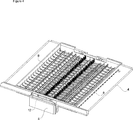
- Figure 2 - is the perspective view of the drawer when the middle surface is at the upper position.
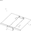
- Figure 3 - is the perspective view of the drawer when the middle surface is at the lower position.
- Figure 4 - is the perspective view of the middle surface on the drawer.
- Figure 5 - is the perspective view of the movement mechanism on the drawer.
- Figure 6 the partial view of the front wall and the middle surface.
- Figure 7 the top view of the channel and the protrusions.
- the dishwasher (1) comprises a body (2), a washing cabin (3) that is disposed inside the body (2) and wherein the washing process is performed and a drawer (9) that is disposed at a region close to the ceiling (T) of the washing cabin (3) and that has a frame (4) that forms the edges of the drawer (9), a front wall (5) and a rear wall (6) oppositely disposed on the frame (4), a movable middle surface (7) whereon small sized items to be washed are placed and more than one side surface (8).
- the frame (4) is preferably composed of wires so as to form the edges of the drawer (9).
- the front wall (5) and the rear wall (6) are arranged on the frame (4).
- the middle surface (7) that extends between the front wall (5) and the rear wall (6) is arranged at the middle section of the frame (4) and the side surfaces (8) are arranged on the sides of the middle surface (7).
- the middle surface (7) and the side surfaces (8) are movable and can be moved inside the drawer (9) by the user.
- the dishwasher (1) of the present invention comprises the middle surface (7) that has a upper position (U) wherein the middle surface (7) enables the area inside the frame (4) to be fully used for placing the items by being adjacent to the side surfaces (8) and a lower position (A) wherein the middle surface (7) moves away from the ceiling (T) of the washing cabin (3) and enables the side surfaces (8) to join by sliding over the same, leaving space on the sides of the frame (4), the dishwasher (1) further comprising a movement mechanism (10) that enables the middles surface (7) to shift between the lover position (A) and the upper position (U). The middle surface (7) moves away from the ceiling (T) of the washing cabin (3) when moved to the lower position (A) by means of the movement mechanism (10).
- the side surfaces (8) can join as the middle surface (7) moves to a lower position between the side surfaces (8).
- the middle surface (7) moves to the lower position (A) and joins the side surfaces (8) together, thus decreasing the size of the drawer (9).
- the side surfaces (8) and the middle surface (7) are locked inside the frame (4).
- the drawer (9) allows the items to be washed inside the washing cabin (3) to extend towards the ceiling (T) of the washing cabin (3) when the side surfaces (8) are joined.
- an empty region is created inside the frame (4).
- the dishwasher (1) comprises the movement mechanism (10) that has more than one driving arm (11) that extends from the rear wall (6) towards the front wall (5) along the edges of the middle surface (7) and that enables the movement mechanism (10) to be disposed onto the middle surface (7), an actuating member (12) that is positioned on the front wall (5) with one of end fixed to the driving arm (11), more than one locking member (13) that is positioned under the middle surface (7) and that is parallel to the front wall (5) and the rear wall (6), a lower level lock (14) that is positioned on the driving arm (11) and that enables the middle surface (7) to be moved to the lower position (A) as the locking member (13) is seated thereon and an upper position lock (15) that enables the middle surface (7) to be locked at the upper position (U).
- the movement mechanism (10) that has more than one driving arm (11) that extends from the rear wall (6) towards the front wall (5) along the edges of the middle surface (7) and that enables the movement mechanism (10) to be disposed onto the middle surface
- the actuating member (12) is disposed on the front wall (5) at a region that can be reached by the user.
- the actuating member (12) is connected to the driving arm (11) or is an extension of the driving arm (11).
- the lower position lock (14) and the upper position lock (15) are disposed on the driving arm (11).
- the middle surface (7) is at the lower position (A) when the locking member (13) on the middle surface (7) is on the lower position lock (14). +When the actuating member (12) is actuated by the user, the middle surface (7) shifts from the lower position (A) to the upper position (U).
- the movement mechanism (10) when the actuating member (12) is actuated by the user, the movement mechanism (10) enables the locking member (13) to be seated onto the lower position lock (14) and the middle surface (7) to be moved to the lower position (A) as the driving arm (11) moves from the front wall (5) towards the rear wall (6).
- the driving arm (11) moves from the front wall (5) towards the rear wall (6).
- the lover position lock (14) and the upper position lock (15) that are disposed on the driving arm (11) are moved.
- the middle surface (7) on the driving arm (11) moves vertically upon the movement of the driving arm (11).
- the locking member (13) under the middle surface (7) is seated onto the lower position lock (14) and the middle surface (7) shifts to the lower position (A) ( Figure 3).
- the movement mechanism (10) when the actuating member (12) is actuated by the user, the movement mechanism (10) enables the locking member (13) to be seated onto the upper position lock (15) and the middle surface (7) to be moved to the upper position (U) as the driving arm (11) moves from the rear wall (6) towards the front wall (5).
- the driving arm (11) moves from the rear wall (6) towards the front wall (5).
- the locking member (13) under the middle surface (7) is seated onto the upper position lock (15) and the middle surface (7) shifts to the upper position (U) ( Figure 2).
- the drawer (9) comprises more than one protrusion (16) disposed on the surface of the middle surface (7) in contact with the front wall (5) and more than one channel (17) that is arranged on the front wall (5), that matches the form of the protrusions (16), enabling the protrusions (16) to be moved vertically therein.
- the middle surface (7) is fixed onto the front wall (5) by means of the protrusions (16).
- the protrusions (16) are fitted into the channel (17) so as to move vertically inside the channel (17).
- the middle surface (7) is enabled to move vertically between the lower position (A) and the upper position (U) without being dislodged from the drawer (9).
- the lower position lock (14) enables the surface of the middle surface (7) to be below the bottom surface of the side surfaces (8) when the middle surface (7) is at the lower position (A).
- the middle surface (7) moves away from the ceiling (T) of the washing cabin (3) and shifts to a position below the bottom of the side surfaces (8).
- the side surfaces (8) can be joined such that that the middle surface (7) is therebelow. Thereby, when not used, the middle surface (7) is prevented from occupying space on the drawer (9).
- the dishwasher (1) comprises the side surfaces (8) that are joined by sliding over the front wall (5) and the rear wall (6) when the middle surface (7) is at the lower position (A).
- the side surfaces (8) can move over the front wall (5) and the rear wall (6) by being released from the edges (K) of the frame (4).
- the dishwasher (1) comprises the drawer (9) wherein the side surfaces (8) can be joined so as to be used at different positions. When joined, the side surfaces (8) can move on the drawer (9) as per the preferences of the user.
- a dishwasher (1) that comprises a drawer (9) that enables the washing capacity to be increased by being able to be used at different sizes.
- the movement mechanism (10) that is disposed on the drawer (9)
- the user can use the necessary regions of the drawer (9), and when not necessary, he/she can decrease the size of the drawer (9) in order to increase the washing space below the drawer (9).
- the drawer (9) can be used in a more practical way.
Landscapes
- Washing And Drying Of Tableware (AREA)
Abstract
La présente invention concerne un lave-vaisselle (1) comprenant un corps (2), une cabine de lavage (3) qui est disposée à l'intérieur du corps (2), le processus de lavage étant effectué dans ladite cabine, et un tiroir (9) disposé au niveau d'une région proche du plafond (T) de la cabine de lavage (3), ledit tiroir comprenant un cadre (4) qui forme les bords du tiroir (9), une paroi avant (5) et une paroi arrière (6), disposées de manière opposée sur le cadre (4), une surface intermédiaire mobile (7) sur laquelle des articles de petite taille à laver sont placés, et plus qu'une surface latérale (8).
Applications Claiming Priority (2)
| Application Number | Priority Date | Filing Date | Title |
|---|---|---|---|
| TR201604531 | 2016-04-07 | ||
| TRA2016/04531 | 2016-04-07 |
Publications (1)
| Publication Number | Publication Date |
|---|---|
| WO2017174565A1 true WO2017174565A1 (fr) | 2017-10-12 |
Family
ID=58632348
Family Applications (1)
| Application Number | Title | Priority Date | Filing Date |
|---|---|---|---|
| PCT/EP2017/057958 Ceased WO2017174565A1 (fr) | 2016-04-07 | 2017-04-04 | Lave-vaisselle |
Country Status (1)
| Country | Link |
|---|---|
| WO (1) | WO2017174565A1 (fr) |
Cited By (3)
| Publication number | Priority date | Publication date | Assignee | Title |
|---|---|---|---|---|
| WO2020136260A1 (fr) * | 2018-12-28 | 2020-07-02 | Arcelik Anonim Sirketi | Lave-vaisselle |
| US20220000332A1 (en) * | 2018-11-13 | 2022-01-06 | Samsung Electronics Co., Ltd. | Rack assembly and dishwasher having same |
| US20230046252A1 (en) * | 2021-08-13 | 2023-02-16 | Haier Us Appliance Solutions, Inc. | Collapsible rack for dishwasher appliance |
Citations (5)
| Publication number | Priority date | Publication date | Assignee | Title |
|---|---|---|---|---|
| DE102008062761B3 (de) * | 2008-12-18 | 2010-03-25 | Miele & Cie. Kg | Besteckschublade für eine Geschirrspülmaschine |
| WO2014002737A1 (fr) | 2012-06-29 | 2014-01-03 | 日立オートモティブシステムズ株式会社 | Capteur de débit d'air thermique |
| WO2014102737A1 (fr) * | 2012-12-31 | 2014-07-03 | Indesit Company S.P.A. | Ramasse-couverts pour lave-vaisselle |
| EP2865316A1 (fr) * | 2013-10-22 | 2015-04-29 | Miele & Cie. KG | Panier de lave-vaisselle |
| CN204909352U (zh) * | 2015-08-17 | 2015-12-30 | 佛山市顺德区美的洗涤电器制造有限公司 | 洗碗机刀叉托盘 |
-
2017
- 2017-04-04 WO PCT/EP2017/057958 patent/WO2017174565A1/fr not_active Ceased
Patent Citations (5)
| Publication number | Priority date | Publication date | Assignee | Title |
|---|---|---|---|---|
| DE102008062761B3 (de) * | 2008-12-18 | 2010-03-25 | Miele & Cie. Kg | Besteckschublade für eine Geschirrspülmaschine |
| WO2014002737A1 (fr) | 2012-06-29 | 2014-01-03 | 日立オートモティブシステムズ株式会社 | Capteur de débit d'air thermique |
| WO2014102737A1 (fr) * | 2012-12-31 | 2014-07-03 | Indesit Company S.P.A. | Ramasse-couverts pour lave-vaisselle |
| EP2865316A1 (fr) * | 2013-10-22 | 2015-04-29 | Miele & Cie. KG | Panier de lave-vaisselle |
| CN204909352U (zh) * | 2015-08-17 | 2015-12-30 | 佛山市顺德区美的洗涤电器制造有限公司 | 洗碗机刀叉托盘 |
Cited By (5)
| Publication number | Priority date | Publication date | Assignee | Title |
|---|---|---|---|---|
| US20220000332A1 (en) * | 2018-11-13 | 2022-01-06 | Samsung Electronics Co., Ltd. | Rack assembly and dishwasher having same |
| US11751750B2 (en) * | 2018-11-13 | 2023-09-12 | Samsung Electronics Co., Ltd. | Rack assembly and dishwasher having same |
| WO2020136260A1 (fr) * | 2018-12-28 | 2020-07-02 | Arcelik Anonim Sirketi | Lave-vaisselle |
| US20230046252A1 (en) * | 2021-08-13 | 2023-02-16 | Haier Us Appliance Solutions, Inc. | Collapsible rack for dishwasher appliance |
| US11712148B2 (en) * | 2021-08-13 | 2023-08-01 | Haier Us Appliance Solutions, Inc. | Collapsible rack for dishwasher appliance |
Similar Documents
| Publication | Publication Date | Title |
|---|---|---|
| EP2242415B1 (fr) | Panier réglable en hauteur pour un lave-vaisselle | |
| EP2818092B1 (fr) | Lave-vaisselle | |
| US8567882B1 (en) | Height adjustment mechanism for rack assemblies of appliances | |
| WO2013000978A1 (fr) | Lave-vaisselle | |
| EP2432367A1 (fr) | Lave-vaisselle comportant un panier à couverts | |
| WO2017174565A1 (fr) | Lave-vaisselle | |
| EP1686883A1 (fr) | Panier pour lave-vaisselle | |
| US20130264920A1 (en) | Silverware basket for a dishwasher appliance | |
| US20110133614A1 (en) | Dishwasher with drawer attached to tub roof | |
| US20170112352A1 (en) | Dishwasher utensil basket | |
| US8905495B2 (en) | Silverware basket for a dishwasher appliance | |
| EP2453788B1 (fr) | Lave-vaisselle et panier à couverts équipant celui-ci | |
| WO2020136260A1 (fr) | Lave-vaisselle | |
| EP2473664A1 (fr) | Machine à laver à distributeur d'agent de nettoyage | |
| EP4434429A1 (fr) | Panier à couverts et lave-vaisselle comprenant celui-ci | |
| JP6064164B2 (ja) | 食器洗い機 | |
| TW201340927A (zh) | 餐具清洗機 | |
| EP2368479A1 (fr) | Lave-vaisselle doté d'un panier supplémentaire | |
| WO2018188879A1 (fr) | Lave-vaisselle | |
| US9107563B2 (en) | Dishwasher and basket fixation apparatus | |
| JP2017176319A (ja) | 食器洗い機 | |
| TR2021012133T (tr) | Bi̇r bulaşik maki̇nesi̇ | |
| WO2018041553A1 (fr) | Porte-verres à utiliser dans des lave-vaisselle | |
| WO2010133677A2 (fr) | Lave-vaisselle et panier à couverts équipant celui-ci | |
| US20140190531A1 (en) | Height adjustment mechanism for rack assemblies for appliances |
Legal Events
| Date | Code | Title | Description |
|---|---|---|---|
| NENP | Non-entry into the national phase |
Ref country code: DE |
|
| 121 | Ep: the epo has been informed by wipo that ep was designated in this application |
Ref document number: 17719177 Country of ref document: EP Kind code of ref document: A1 |
|
| 122 | Ep: pct application non-entry in european phase |
Ref document number: 17719177 Country of ref document: EP Kind code of ref document: A1 |