WO2017175293A1 - Ensemble d'accouplement d'arbres, procédé de raccordement de deux arbres avec un ensemble d'accouplement d'arbres, et procédé d'entretien - Google Patents
Ensemble d'accouplement d'arbres, procédé de raccordement de deux arbres avec un ensemble d'accouplement d'arbres, et procédé d'entretien Download PDFInfo
- Publication number
- WO2017175293A1 WO2017175293A1 PCT/JP2016/061075 JP2016061075W WO2017175293A1 WO 2017175293 A1 WO2017175293 A1 WO 2017175293A1 JP 2016061075 W JP2016061075 W JP 2016061075W WO 2017175293 A1 WO2017175293 A1 WO 2017175293A1
- Authority
- WO
- WIPO (PCT)
- Prior art keywords
- coupling
- hub
- shaft
- notch
- yoke
- Prior art date
- Legal status (The legal status is an assumption and is not a legal conclusion. Google has not performed a legal analysis and makes no representation as to the accuracy of the status listed.)
- Ceased
Links
Images


Classifications
-
- F—MECHANICAL ENGINEERING; LIGHTING; HEATING; WEAPONS; BLASTING
- F16—ENGINEERING ELEMENTS AND UNITS; GENERAL MEASURES FOR PRODUCING AND MAINTAINING EFFECTIVE FUNCTIONING OF MACHINES OR INSTALLATIONS; THERMAL INSULATION IN GENERAL
- F16D—COUPLINGS FOR TRANSMITTING ROTATION; CLUTCHES; BRAKES
- F16D3/00—Yielding couplings, i.e. with means permitting movement between the connected parts during the drive
- F16D3/02—Yielding couplings, i.e. with means permitting movement between the connected parts during the drive adapted to specific functions
- F16D3/04—Yielding couplings, i.e. with means permitting movement between the connected parts during the drive adapted to specific functions specially adapted to allow radial displacement, e.g. Oldham couplings
Definitions
- the present invention relates to a shaft coupling assembly that can cope with misalignment, a method for connecting two shafts by the shaft coupling assembly, and a maintenance method.
- both rotation shafts are spaced apart and connected by a coupling.
- misalignment usually classified into eccentricity, declination, and end play occurs between two shafts of the output rotation shaft of the engine or motor and the input rotation shaft of the pump.
- a part of the structure includes a flexible structure that can absorb misalignment.
- Patent Document 1 discloses a rigid coupling device, but includes a flexible structure in which a slit perpendicular to an axis is inserted (Patent Document 1, Claims and FIG. 1).
- Patent Document 2 discloses a shaft coupling that has torsional rigidity and allows misalignment, but partially includes a flexible structure called a torsion spring mechanism.
- the torsion spring mechanism can “pivot and move in the axial direction to absorb slight misalignment” (paragraph 0048, lines 1 to 4 of Patent Document 2), “preload is applied” (Paragraph 0050, third line of Patent Document 2).
- U.S. Pat. No. 6,057,089 provides a method of connecting two shafts by a shaft coupling assembly comprising a rigid member including a sleeve (FIG. 1 of U.S. Pat. It does not provide a way to connect the two shafts.
- Patent Document 4 Japanese Patent Publication No. 2006-3779918
- This invention is an invention composed only of a rigid structure and does not include a flexible structure, but even if misalignment adjustment can be adjusted at the initial stage of installation, in particular, misalignment due to aging or wear of the support structure, or comparison It is difficult to absorb the misalignment caused by the dynamic deformation of the support structure in the case of mounting on a ship placed under a flexible structure. For this reason, Patent Document 4 seems to have a separate wear detection means so that secular change can be observed (Claim 1 of Patent Document 4). This makes it possible to indirectly understand that it is difficult to assemble a coupling that is composed only of a rigid structure and does not include a flexible structure, and to realize the installation and easy maintenance of a rotating machine. The inventor of the present application has tackled this problem from the front in order to achieve both a coupling configuration consisting entirely of a rigid structure and misalignment absorption.
- Non-Patent Document 1 uses a laser measuring instrument and computer-aided software in cooperation to determine the amount of misalignment. Disclose technology for precise digital measurement.
- Non-Patent Document 1 even if misalignment is measured by modernization techniques, correction of this misalignment can be done by adjusting the position and inclination of the mounting pedestal and inserting spacers into the pedestal. Usually, there is no choice but to do physical and mechanical care such as adjusting the thickness. Surprisingly, in many cases, alignment adjustment methods must rely on primitive human machine work such as adjusting the position of the mounting pedestal, inserting spacers into the pedestal, experience and manual intuition. It is.
- any member has to be made a flexible structure after all.
- One approach of flexible structure is to have a thin structure part in part like a slit and include a soft structure, partly a spring structure part to include a soft structure, or like a flexible coupling, In general, a bellows-like shape is included, or a flexible material such as an elastic material or rubber is used as a material for the connection portion to include a flexible structure.
- Patent Document 5 is a detachable coupling, and “the present invention can shorten the axial length as much as possible, and can be used for a joint of eccentricity, declination, and end play. "Providing a propeller shaft structure that can absorb all of the three disadvantageous misalignment elements and that is easy to attach and detach to and from the input / output shaft, and that is easy to assemble and maintain" (paragraph 0004 of Patent Document 5).
- a main object of the present invention is a shaft coupling assembly having a novel structure that allows high torque transmission and is easy to assemble and disassemble in a compact space, and has an eccentric, declination, and end play cup.
- the object is to provide a shaft coupling assembly that is capable of absorbing all three misalignment elements unavoidable for the ring. That is, (1) It is inconvenient for coupling of eccentricity, declination, and end play and can absorb all three misalignment elements that are generally inevitable. It is easy (3) It is possible to provide a coupling with a large common torque It is an object of the present invention to provide a shaft coupling assembly and a method for connecting two shafts by the shaft coupling assembly and a maintenance method.
- the present invention that has solved the above problems is as follows.
- ⁇ Invention of Claim 1> The following parts connecting the two torque transmission shafts: A first hub that is matable with the first shaft; A second hub that is matable with the second shaft; With a coupling disc; Two sets of coupling blocks, each of which is engageable or connectable to the hub and the coupling disk; and an outer periphery of any one of the two members of the hub or the coupling disk
- the surface is provided with a total of two pairs of notches that are opposed to each other by 180 ° along the axial direction with the shaft core interposed therebetween, and covers the outer peripheral surface of the member including the notches.
- a sleeve capable of sealing the notch with respect to the open space on the outer peripheral side of the member;
- a shaft coupling assembly comprising: The notch is a pair of notches along the axial direction facing the outer periphery of only one of the two components of the hub or the coupling disk, with the shaft core sandwiched by 180 °.
- the remaining two types of members that do not have the notch portion are shaft couplings that are 180 ° opposite each other and have an insert hole along the axial direction.
- the method of connecting two shafts by an assembly includes the following steps: A shaft alignment step of roughly aligning the first shaft and the second shaft in advance; A first hub connecting step of inserting the first shaft into the first hub and coupling both members; A second hub connecting step of inserting the second shaft into the second hub and coupling both members; Coupling the first hub and the second hub, the following steps: The coupling block is engaged with the member having the notch portion at the notch portion, and the coupling block engaging and connecting step of connecting both members; and the coupling block does not have the notch portion.
- a coupling block constraining connection stage connected and constrained to the insert hole of the member; And a sleeve step of sealing the coupling block engaged with the notch after the assembly by the sleeve covering the notch to the notch. Connecting two shafts by a shaft coupling assembly.
- the notch used in the present invention is an open notch, which forms an open space in the radial direction of the member having the notch and can be taken in and out for engagement from the open to the notch.
- the shaft coupling assembly used in the present method uses a sleeve member that covers a member having a notch, and the coupling block can be sealed in the notch that is covered with the sleeve during assembly.
- the both ends of the coupling block are sandwiched between the coupling disk surface and the flange end surface of the hub, and after assembly of the shaft coupling assembly, as a whole, are shielded from the external environment such as dust, moisture and salt.
- a new shaft coupling assembly that allows transmission of high torque while being easy to assemble and disassemble in a compact space, and is inevitable for misalignment, declination and end play coupling
- a method of connecting two shafts by a shaft coupling assembly that substantially provides a shaft coupling assembly capable of absorbing all three elements.
- the coupling step includes connecting means (1) and (2) described below, (1) One set of notch portions that can engage the coupling block in the axial direction on the outer peripheral surface that faces the 180 ° angle with the shaft core sandwiched between the first hub and the second hub. (2) Two sets of connecting means are used on the disk surface opposite to each other at 180 ° with the insertion hole into which the coupling block can be inserted along the axial direction sandwiching the disk center of the coupling disk.
- a coupling process comprising: The sleeve is a separate sleeve that covers the outer circumferences of the first hub and the second hub, and the sleeve covers the notch, and after the sleeve is assembled, the notch is an open space on the outer circumference side of the hub.
- a first yoke configuration in which the ring block is movable in the axial direction and misalignment of the end play is allowed; and a second yoke substantially formed by the second hub and the coupling block engaged therewith The coupling block is movable in the radial direction within the notch, and the yoke is misaligned.
- the coupling block In the notch, the coupling block can be tilted in the axial direction so that misalignment of the deflection angle of the yoke can be allowed, and in the notch, the coupling block is Second yoke configuration that can move in the axial direction and also allow misalignment of the end play;
- the first yoke and the second yoke are configured to allow misalignment of eccentricity and declination of each yoke, and in total, allow misalignment of decentering and declination in all directions.
- the method of connecting two shafts by the shaft coupling assembly of the present invention according to claim 2 is easy to couple, and the shafts can be easily connected.
- the present invention allows for eccentricity, declination and end play. Even if the shaft coupling assembly of the present invention is retrofitted after both shafts are installed, misalignment adjustment work is not necessarily required for connection with the shaft coupling assembly.
- the notch of the first hub is one of the two sets of coupling blocks. Engage with one end of a pair of coupling blocks to form a virtual first yoke after assembly, and the other end engages with a pair of opposing insert holes in the coupling disk And allowing misalignment as the virtual yoke integral, and A notch portion of the second hub engages with one end portion of the remaining coupling block of the two sets of coupling blocks to form a second virtual yoke after assembly.
- This yoke is a method of connecting two shafts by a shaft coupling assembly which is connected to a pair of opposed insert holes of the coupling disk at the other end and allows misalignment as a virtual yoke integral.
- a first hub that can be fitted to a first shaft that has a pair of notches along the axial direction with a shaft core sandwiched between the outer periphery and 180 °; A first sleeve covering the hub from the first shaft side; A second hub that can be fitted to a second shaft that has a pair of notches along the axial direction with a shaft core sandwiched between the outer periphery and 180 °; A second sleeve covering the hub from the second shaft side; A coupling disk having two pairs of insert holes that are 180 ° opposite to each other across the center of the disk and that extend along the axial direction; and two sets of coupling blocks that form two pairs
- the eccentricity and the deflection angle included in the present invention are included.
- the end play permission function eliminates the need for including misalignment adjustment work as an
- the first sleeve seals the coupling block engaged with the notch of the first hub in the notch, and the second sleeve is engaged with the notch of the second hub.
- the coupling block is sealed in the notch, and the coupling block is not separated from the engaged state.
- the coupling step includes connecting means (3) and (4) described below, (3) Two sets of notches capable of engaging the coupling block along the axial direction on the outer peripheral surface facing the 180 ° across the disk central axis of the coupling disk.
- a pair of connecting means are used on the hub flange surfaces facing each other by sandwiching the insert holes that can be inserted along the axis of each of the first hub and the second hub, and the coupling process includes the following steps: Each stage: A coupling block engaging and connecting step of engaging the outer surface of two sets of the coupling blocks with the notch on the coupling disk; A coupling block first hub constraining connection step, wherein the first hub is screwed with a bolt for inserting an end face of the set of coupling blocks into the insert hole; and the remaining set of the second hub A coupling block second hub restraint connection stage in which an end face of the coupling block is screwed with a bolt inserted into the insert hole; A coupling process comprising: The sleeve is a sleeve that covers an outer periphery of the coupling disk, and the notch is sealed from an open space on the outer peripheral side of the coupling disk after assembly by the sleeve that covers the notch.
- the coupling block can be tilted in the axial direction to allow misalignment of the deflection angle of the yoke, and in the notch, the coupling block has a shaft.
- a first yoke configuration that is movable in the direction and also allows end play misalignment; and a second yoke substantially formed by the second hub and the coupling block, in the notch
- the coupling block can be moved in the radial direction, and misalignment of the eccentricity of the yoke can be allowed.
- the coupling block In the notch, the coupling block can be tilted in the axial direction, so that misalignment of the deflection angle of the yoke can be allowed, and in the notch, the coupling block can be moved in the axial direction.
- Second yoke configuration that allows for play misalignment;
- the first yoke and the second yoke are configured so that the yokes can integrally accept eccentricity and declination misalignment, and in total, allow misalignment of eccentricity and declination in all directions.
- the coupling can be easily assembled and the shaft can be easily connected.
- the present invention allows for eccentricity, declination and end play. Even if the shaft coupling assembly of the present invention is retrofitted after both shafts are installed, misalignment adjustment work is not necessarily required for connection with the shaft coupling assembly.
- the end face of the coupling block as a set on the first hub.
- the first yoke is formed with a bolt inserted into the insert hole, and the coupling block is engaged with a pair of opposed notches of the coupling disk at the side surface, and the virtual Allows misalignment of the yoke, and
- the end face of the remaining set of the coupling block is screwed to the second hub with a bolt inserted into the insert hole to form a second imaginary yoke, and the second yoke is a side portion of the second hub.
- two shafts are connected by a shaft coupling assembly that engages with a pair of opposed notches of a coupling disk and allows misalignment of the virtual yoke.
- the end play permission function eliminates the need for
- the sleeve seals the coupling block engaged with the notch of the coupling disk in the notch, and the second sleeve is the cup engaged with the notch of the second hub.
- the ring block is sealed in the notch, and the coupling block does not leave the engaged state.
- the torque transmission structure is as follows: A first hub that can be fitted to a first shaft that has a pair of notches along the axial direction with a shaft core sandwiched between the outer periphery and 180 °; A second hub that can be fitted to a second shaft that has a pair of notches along the axial direction with a shaft core sandwiched between the outer periphery and 180 °; A coupling disk having two pairs of insert holes that are 180 ° opposite to each other across the center of the disk and extend along the axial direction; and two sets of coupling blocks, each having two pairs
- a shaft coupling assembly comprising: The notch portion of the first hub engages with one end portion of a pair of coupling blocks of the two sets of the two sets, and a first yoke can be formed after assembly
- the coupling block engages from the disk surface side of one end to a pair of opposing insert holes of the coupling disk at the other end, and allows misalignment as the first yoke integrated with the other, and
- the notch portion of the second hub engages with one end portion of the remaining pair of coupling blocks of the two sets of coupling blocks so that a second yoke can be formed after assembly.
- the coupling block is movable in the axial direction within the notch, After assembly, the first sleeve seals the coupling block engaged with the notch portion of the first hub in the notch portion, and the second sleeve seals the coupling block to the notch portion.
- a shaft coupling assembly After assembly, the first sleeve seals the coupling block engaged with the notch portion of the first hub in the notch portion, and the second sleeve seals the coupling block to the notch portion.
- one set is defined as two, and each coupling block corresponds to one hub.
- the hub that can be fitted to the first shaft is the first hub and the other is the second hub, but the external shapes may be the same.
- the hub is formed with a pair of cutout portions along the axial direction so as to face the outer peripheral surface with the shaft core sandwiched by 180 °.
- a coupling block is engaged with the notch.
- One end of one coupling block is accommodated in one notch.
- a coupling disk is disposed between the hubs.
- the coupling disk is formed with four insert holes, and two insert holes that are opposed to each other by 180 ° across the center of the disk are engaged with the same hub. Two coupling blocks are engaged.
- Each hub is engaged with the coupling block from the surfaces facing each other.
- the two coupling blocks engage with the hub on one side and are arranged like a first yoke and a second yoke.
- “so” means that the sleeve that covers the hub is assembled, sealed by being surrounded by the notch of the sleeve and the hub, and the yoke is configured only after assembly. expressing.
- a notch portion of the first hub engages to form a coupling block like a first yoke, and the coupling block sandwiches the axis of the coupling disc between the sleeve and the coupling disc end.
- the allowable misalignment direction of one yoke is the X-axis direction
- the other yoke surface crosses the X-axis in accordance with the insert hole of the coupling disk after assembly with one yoke surface, and one of them is the Y-axis direction.
- misalignment allowed on the other yoke surface is also allowed in the Y-axis direction, and misalignment in an XY axis constituting plane, that is, in any direction is allowed by both yokes.
- the coupling block can be moved in the axial direction within the notch, and misalignment of the end play is allowed within the notch in relation to the coupling block.
- end play is allowed by the misalignment allowed in the first yoke, the misalignment allowed in the second yoke and the end play, and the sliding of the coupling block in the insert hole. Misalignment, eccentricity, declination, and end play are acceptable.
- the torque transmission structure is as follows: A first hub that can be fitted to a first shaft having a pair of insert holes that are 180 ° opposite to each other with an axial center sandwiched between them; A second hub that can be fitted to a second shaft having a pair of insert holes that are 180 ° opposite to each other with an axial center sandwiched between them; A coupling disk having two pairs of notch portions along the axial direction with the disk center sandwiched between the outer peripheral surface and 180 °; A sleeve covering the notch of the coupling disk; and two sets of coupling blocks, each of which is a set of two pieces; A shaft coupling assembly comprising: The end face of one coupling block of the two coupling blocks that penetrates the insert hole of the first hub and sets the two is screwed and connected by bolts to the second after the assembly.
- a yoke can be formed, and the coupling block engages with the pair of opposed notches of the coupling disk on the outer surface, and allows misalignment of the first yoke; and Through the insert hole of the second hub, the end face of the remaining coupling block of the two sets of coupling blocks is screwed and connected with bolts to form a second yoke after assembly.
- the coupling block engages with the pair of opposed notches of the coupling disk on the outer surface, and allows misalignment of the second yoke.
- the sleeve is a shaft coupling assembly that seals the coupling block to the notch.
- each coupling block corresponds to one hub.
- the hub that can be fitted to the first shaft is the first hub and the other is the second hub, but the external shapes may be the same.
- a pair of insert holes are formed along the axial direction so as to be opposed to each other by 180 ° with the shaft core interposed therebetween.
- the coupling block is fixedly connected to the coupling block with screws by the bolts penetrating the insert hole. When the coupling block is fastened to the first hub, the first yoke is formed.
- One coupling block is accommodated and engaged with one notch of a pair of notches formed along the axial direction so as to face the outer peripheral surface of the coupling disk at 180 ° across the center of the disk.
- Coupling discs can be placed between the hubs, but the coupling disc has two sets of notches, and a total of four notches are formed.
- Two coupling blocks fastened to the same hub are engaged with a pair of notches that are 180 ° opposite to each other with the disk center interposed therebetween and extend in the axial direction. After assembly, each hub is engaged with the coupling disk at the flange surfaces on the opposite sides.
- the two coupling blocks are screwed together with bolts penetrating the flange surface of the hub and the flange hole on one side to form a first yoke and a second yoke.
- the coupling block of the first yoke formed by the coupling block that is screwed and connected through the insert hole of the first hub engages with a pair of notches facing each other across the axis of the coupling disk
- the sleeve covering the coupling disk it is sealed in the space formed by the notch and the sleeve, allowing for eccentricity and declination of the yoke and misalignment of the end play, and the notch depth direction
- the inclination and movement of the outer yoke are restricted, if the misalignment permissible direction of one yoke is the X-axis misalignment permissible direction, the other yoke surface becomes the insert hole of the coupling disk after assembly.
- the shaft coupling assembly can be constituted by only a rigid member.
- the present invention provides all types of misalignment, eccentricity and declination based on misalignment allowed in the first yoke, misalignment allowed in the second yoke, and sliding of the coupling block in the insert hole. And a shaft coupling assembly that allows end play. Compared to a universal joint, axial misalignment and end play are also realized with the above configuration, and this is a shaft coupling assembly that provides space saving, simpler configuration, and lower cost.
- a flexible coupling member, thin plate, spring member, or other flexible structural member is not required, and the shaft coupling assembly is composed only of a rigid torque transmission structure component, and can provide a high torque function.
- a flexible member such as a flexible member, a thin plate, or a spring member is not required, but even if a viscoelastic member or engineering plastic having a certain degree of rigidity is used, high torque transmission can be achieved to some extent.
- the notch may have any shape that allows the yoke to move in the radial direction, and the insert hole only needs to allow the axial movement. If the notch is a notch with a substantially rectangular cross section due to the combination of the shape of the coupling block, and the insert hole is a substantially circular hole, the coupling block is a cylinder with a diameter smaller than its side length in the honest cuboid A combination of coupling blocks having a combination of the above is advantageous in terms of positioning convenience and processing, which is preferable. This configuration is simple and convenient for assembly and maintenance.
- a method of maintaining a shaft coupling assembly including two shafts connected in a manner of connecting two shafts by the shaft coupling assembly of claim 2 includes the following steps: Removing the sleeve from the hub to expose the notch; After the, A method for maintaining a shaft coupling assembly, comprising the step of replacing the coupling block without disassembling a shaft coupling assembly member other than the sleeve.
- a method of maintaining a shaft coupling assembly including two shafts connected in a manner of connecting two shafts by the shaft coupling assembly of claim 3 includes the following steps: Removing the sleeve from the coupling disc to expose the notch; After the, A method for maintaining a shaft coupling assembly, comprising the step of replacing the coupling block without disassembling a shaft coupling assembly member other than the sleeve.
- the shaft coupling assembly method of the present invention provides a method for easily maintaining the coupling. This is because each member, which is a constituent means of the present invention, provides a coupling that allows for eccentricity, declination, and end play when assembled. Even if the shaft coupling assembly of the present invention is retrofitted after both shafts are installed, misalignment adjustment work is not necessarily required for connection with the shaft coupling assembly.
- ⁇ Invention of Claim 12> The method according to any one of claims 1 to 3, 10 or 11, wherein the coupling disk is formed by stacking a plurality of disks. (Function and effect)
- the present invention provides a method that makes it easier to assemble / maintain the shaft coupling assembly even when the separation between the first shaft and the second shaft is smaller.
- ⁇ Invention of Claim 13> The shaft coupling assembly according to claim 4 or 5, wherein the coupling disk is formed by stacking a plurality of disks.
- the present invention makes it easier to assemble the shaft coupling assembly even when the separation between the first shaft and the second shaft is smaller.
- a shaft coupling assembly having a novel structure that enables transmission of high torque and is easy to assemble and disassemble in a compact space.
- An object of the present invention is to substantially provide a shaft coupling assembly, an assembly method thereof, and a maintenance method capable of absorbing all three misalignment elements which are inconvenient and unavoidable for the coupling. That is, (1) Capable of absorbing all three misalignment elements that are inconvenient for coupling, including eccentricity, declination, and end play. (2) Easy to attach and detach the coupling even when the shafts on both sides are installed and fixed. (3) A coupling with a large service torque can be provided (4) Provided is a shaft coupling assembly having a new structure that is easy to assemble and disassemble in a compact space.
- 1 is an exploded perspective schematic view of a shaft coupling assembly 1 which is an embodiment of a shaft coupling assembly according to the present invention.
- 1 is a schematic perspective view of an assembled state of a shaft coupling assembly 1 which is an embodiment of a shaft coupling assembly according to the present invention.
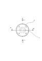
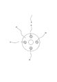
- It is a front schematic diagram of the assembly state of the shaft coupling assembly 1 which is one Embodiment of the shaft coupling assembly which concerns on this invention.
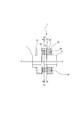
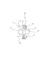
- It is a vertical longitudinal cross-sectional schematic diagram of the assembly state of the shaft coupling assembly 1 which is one Embodiment of the shaft coupling assembly which concerns on this invention.
- It is a horizontal longitudinal cross-sectional schematic diagram of the assembly state of the shaft coupling assembly 1 which is one Embodiment of the shaft coupling assembly which concerns on this invention.
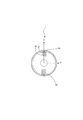
- 1 is a cross-sectional schematic diagram of a first hub 11 part in an assembled state of a shaft coupling assembly 1 which is an embodiment of a shaft coupling assembly according to the present invention. It is a 2nd hub 21 part cross-sectional schematic diagram of the assembly state of the shaft coupling assembly 1 which is one Embodiment of the shaft coupling assembly which concerns on this invention. 1 is a schematic cross-sectional view of a coupling disk 50 part in an assembled state of a shaft coupling assembly 1 which is an embodiment of a shaft coupling assembly according to the present invention. It is a disassembled perspective schematic diagram of the shaft coupling assembly 100 which is other embodiment of the shaft coupling assembly which concerns on this invention.
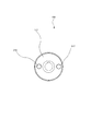
- FIG. 1 is a cross-sectional schematic diagram of a coupling disk 150 part in an assembled state of a shaft coupling assembly 100 which is an embodiment of a shaft coupling assembly according to the present invention.
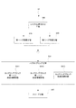
- 3 is a step basic flowchart S0 of a method for connecting two shafts by a shaft coupling assembly according to the present invention;
- 4 is a step flowchart S1 according to an embodiment of a method for connecting two shafts by a shaft coupling assembly according to the present invention.
- 6 is a step flowchart S2 according to another embodiment of a method for connecting two shafts by a shaft coupling assembly according to the present invention.
- 4 is a step integration flowchart S0 ′ of a method for connecting two shafts by a shaft coupling assembly according to the present invention;
- FIG. 1 shows an exploded perspective schematic view of one embodiment of a shaft coupling assembly according to the present invention
- FIG. 2 shows a perspective schematic view of an assembled state of one embodiment of a shaft coupling assembly according to the present invention
- FIG. 3 is a schematic front view of an assembled state of an embodiment of a shaft coupling assembly according to the present invention
- FIG. 4 is a schematic vertical longitudinal sectional view of an assembled state of an embodiment of a shaft coupling assembly according to the present invention.
- FIG. 5 shows a schematic diagram of a horizontal longitudinal section of an embodiment of a shaft coupling assembly according to the present invention
- FIG. 6 shows an assembly of an embodiment of a shaft coupling assembly according to the present invention.
- FIG. 7 is a schematic cross-sectional view of the first hub portion in a state
- FIG. 8 is a schematic cross-sectional view
- FIG. 8 is a schematic cross-sectional view of a coupling disk 50 part in an assembled state of the shaft coupling assembly 1 which is an embodiment of the shaft coupling assembly according to the present invention.
- the schematic cross-sectional view only the cross section of the coupling block is hatched.
- FIG. 15 shows a basic step flow chart S0 of a method of connecting two shafts by a shaft coupling assembly according to the present invention
- FIG. 16 shows a method coupling by the shaft coupling assembly according to the present invention
- FIG. 17 shows a step flowchart S1 according to an embodiment of a method for connecting two shafts
- FIG. 17 shows a step flowchart S2 according to another embodiment of a method for connecting two shafts by a shaft coupling assembly according to the present invention
- FIG. 18 shows a step integration flow chart S0 ′ of a method for connecting two shafts by a shaft coupling assembly according to the present invention.
- the hub coupling process includes a coupling block engagement and connection stage (S301) and a coupling block restraint / continuation stage (S302).
- Sleeve process (S40) including.
- the shaft coupling assembly according to the embodiment of the present invention used in the step basic flowchart S0 will be outlined.
- a shaft coupling assembly includes: The following parts connecting the two torque transmission shafts: A first hub that is matable with the first shaft; A second hub that is matable with the second shaft; And a pair of notches along the axial direction AX across the outer periphery of any one of the two members of the hub or the coupling disc with the shaft core sandwiched 180 ° therebetween. Including a sleeve that covers the outer peripheral surface of the member including the notch, and can seal the notch from the open space on the outer peripheral side of the member.
- the other kind of member that does not have the notch is a shaft coupling assembly that is a member that has an insert hole along the axial direction with 180 degrees facing the shaft core.
- FIG. 1 is an exploded perspective schematic view of an embodiment of a shaft coupling assembly according to the present invention
- FIG. 2 is a schematic perspective view of an assembled state of an embodiment of a shaft coupling assembly according to the present invention
- FIG. 3 is according to the present invention.
- FIG. 4 is a schematic front view of an assembled state of an embodiment of a shaft coupling assembly
- FIG. 4 is a schematic vertical vertical sectional view of an assembled state of an embodiment of a shaft coupling assembly according to the present invention
- FIG. 5 is a shaft coupling assembly according to the present invention.
- FIG. 6 is a schematic diagram of a horizontal longitudinal section in an assembled state of an embodiment of the present invention
- FIG. 6 is a schematic diagram of a transverse section of a first hub portion in an assembled state of an embodiment of a shaft coupling assembly according to the present invention
- FIG. FIG. 8 is a schematic cross-sectional view of the second hub portion in an assembled state according to an embodiment of the assembly
- FIG. Referring to the coupling disc 50 parts cross-sectional schematic view of the assembled state of the shaft coupling assembly 1 according to an embodiment of Li, detailing an embodiment of a shaft coupling assembly 1 according to the present invention.
- a shaft coupling assembly 1 includes: The following members connecting the two torque transmission shafts 10, 20: A first hub 11 that can be fitted to the first shaft 10; A second hub 21 that can be fitted to the second shaft 20; The first shaft 10 is fitted into the inner hole of the first hub 11 by a key, and the second shaft 20 is fitted into the inner hole of the first hub 21 by, for example, a key.
- the torque transmission structure is as follows: A first hub 11 that has a pair of notches 12 and 13 along the axial direction AX and is opposed to the outer peripheral surface by sandwiching the shaft core 4 at 180 °; A second hub 21 that has a pair of notches 22 and 23 along the axial direction AX and that faces the outer circumferential surface with the shaft core 2 sandwiched by 180 ° and that can be fitted to the second shaft 20; Two pairs of insert discs with two pairs of insert holes along the axial direction AX across the disc center 3 with 180 ° facing each other, (30, 31) (40, 41); and two sets of two Coupling blocks (32, 33) (42, 43); In addition, the following: A first sleeve 15 covering the first hub 11 from the first shaft 10 side to cover the notches 12 and 13; and a second hub 21 from the second shaft 20 side to the notches 22 and 23.
- a second sleeve 25 covering A shaft coupling assembly 1 comprising: One end of a set of coupling blocks (32, 33) out of two sets of coupling blocks 32, 33, 42, 43 in which the notches 12 and 13 of the first hub 11 are the two sets.
- the first yoke 34 can be formed after assembly by engaging with the portion, and the coupling blocks 32 and 33 are connected at one end to the pair of insert holes 30 and 31 facing the coupling disk 50 at the other end. Joining from the disk surface 51 side, allowing misalignment as the first yoke 34 integrated, and The notches 22 and 23 of the second hub 21 are engaged with one end of the remaining coupling blocks (42, 43) of the two sets of coupling blocks (32, 33) (42, 43).
- the second yoke 44 can be formed after the assembly, and the second yoke 44 is connected to the pair of insert holes 40, 41 facing the coupling disk 50 at the other end to the disk surface 52 side at the other end.
- the second yoke 44 is allowed to be misaligned, and
- the coupling blocks 32, 33, 42, 43 are movable in the axial direction AX in the notches 12, 13, 22, 23,
- the first sleeve 15 is fastened integrally with the hub 11 by a bolt 16. After assembly, the first sleeve 15 is engaged with the notches 12, 13 of the first hub 11.
- the second sleeve 25 is capable of sealing the coupling blocks 42 and 43 to the notches 22 and 23 by being fastened together with the hub 21 by bolts 26.
- a shaft coupling assembly 1 is shown.
- the coupling disk 50 is disposed between the hubs 11 and 21, and the four insert holes 30, 31, 40, and 41 of the coupling disk 50 are formed.
- Two coupling blocks engaged with the same hub are joined to two insert holes that are 180 ° opposite each other across the center as a set (32, 33) (42, 43).
- the hubs 11 and 21 are engaged with coupling blocks 32 and 33 and 42 and 43 from opposite surfaces 51 and 52 of the coupling disk 50.
- the two coupling blocks 32 and 33 are arranged so as to engage with the hub 11 on one side to form the first yoke 34.
- “so” means that the sleeve 15 covering the hub 11 is assembled by fastening the bolt 16 and is surrounded by the sleeve 15 and the notches 12 and 13 of the hub 11.
- the coupling block 32 similarly has the end surface 51 of the coupling disk 50, the inner surface of the notch, and the sleeve 15.
- it is expressed as “like” in the sense that the yoke shape 34 is constructed only after assembly, and this yoke 34 is used as a yoke as an independent form joined as a substance. Since it does not exist, here it is expressed as forming a yoke, functionally equivalent to a yoke It is characterized by exhibiting the use effect.
- the second hub 21 is the same, and the notches 22 and 23 are engaged to form coupling blocks 42 and 43 like the second yoke 44.
- the coupling blocks 42 and 43 are formed of sleeves. 25 and the end face 52 of the coupling disk 50 are joined to a pair of insert holes 40 and 41 facing each other with the axis 3 of the coupling disk 50 interposed therebetween.
- the coupling block 42 is In the space surrounded by the end surface 52 of the coupling disk 50, the inner surface 24 of the notch and the inner surface 27 of the sleeve 25, the coupling block 43 similarly has the end surface 52 of the coupling disk 50, the inner surface of the notch and the sleeve.
- the yoke 44 is allowed to be misaligned, and the shaft outside the yoke surface It can is restrained.
- the allowable misalignment direction of one yoke 34 is the X-axis direction, and the other yoke 44 surface crosses the X-axis in accordance with one yoke 34 surface and the insert holes 40 and 41 of the coupling disk 50 after assembly. If one of them is in the Y-axis direction, the misalignment allowed by the other yoke surface 44 is also allowed in the Y-axis direction, and both yokes 34 and 44 are misaligned in the plane of the XY axis, that is, in any direction. Exhibits the effect that is allowed.
- the coupling blocks 32, 33, 42, 43 can move in the axial direction in the notches 12, 13, 21, 22, and end play misalignment is also coupled in the notches 12, 13, 22, 23. It is acceptable in relation to the block. Insertion into the insert holes 30, 31, 40, 41 may be connected by engagement, in which case the engagement between the insert holes 30, 31, 40, 41 and the coupling blocks 32, 33, 42, 43. Thus, the rotational motion is restricted and the transmission is exhibited, and at the same time, the end play misalignment is allowed even in the engagement.
- a torque transmission structure can be constructed.
- FIG. 9 An exploded perspective schematic view of a shaft coupling assembly 100, which is another embodiment of the shaft coupling assembly according to the present invention, and FIG. 10 according to the present invention.
- FIG. 11 is a schematic perspective view of an assembled state of a shaft coupling assembly 100 as another embodiment of the shaft coupling assembly
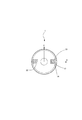
- FIG. 11 is a schematic front view of the assembled state of the shaft coupling assembly 100 according to the present invention
- FIG. 13 is a schematic vertical vertical sectional view of an assembled state of an embodiment of a shaft coupling assembly 100 according to the invention
- FIG. 13 is a schematic vertical vertical sectional view of an assembled state of an embodiment of the shaft coupling assembly 100 according to the present invention.
- 1 is an embodiment of a shaft coupling assembly according to the invention. Detail while showing the coupling disk 150 parts schematic cross-sectional view of the assembled state of the shaft coupling assembly 100.
- a shaft coupling assembly 100 includes: The torque transmission structure is as follows: A first hub 111 that can be fitted to the first shaft 10 having a pair of insert holes 116 and 117 that are 180 ° opposite to each other with the shaft core 101 sandwiched therebetween along the axial direction AX; A second hub 121 that can be fitted to the second shaft 20 having a pair of insert holes 226 and 227 that are opposed to each other by 180 ° along the axial direction with the shaft core 102 interposed therebetween; A coupling disk 150 having two pairs (112, 113) (122, 123) of a pair of notches along the axial direction AX with the disk center 103 sandwiched between the outer peripheral surfaces and 180 °; A sleeve 115 that covers the notches 112, 113, 122, 123 of the coupling disk 150; and two sets (132, 133) (142, 143) of coupling blocks, each of which includes two sets; A shaft coupling assembly 100 comprising: One set of coupling blocks 132, 133 out of two
- the first yoke 135 can be formed after assembly by screw fastening connection with one end and bolts 216, 217, and the coupling blocks 132, 133 are formed on the outer circumference of the pair of the cutting discs facing the coupling disk 150. Engaging the notches 112 and 113, allowing misalignment of the first yoke 135, and One end of the remaining pair of coupling blocks 142, 143 of the two sets of coupling blocks 132, 133, 142, 143 and bolts 126, 127 through the insert holes 226, 227 of the second hub 121.
- the second yoke 145 can be formed after assembly by screw fastening connection, and the coupling blocks 142 and 143 are formed on the pair of notches 123 and 124 facing the coupling disk 150 on the outer periphery thereof. Engaging and allowing misalignment of the second yoke 145; After the assembly, the sleeve 115 has the coupling blocks 132, 133, 142, and 143 in the notches 112, 113, 122, and 123, and the inner surfaces 114 and 124 of the end surfaces 151 and 152 of the coupling disk 150, respectively.
- the shaft coupling assembly 100 is sealed in a space surrounded by the inner surface 118 of the sleeve 115 and the like.
- the term “one set” means two, and each coupling block corresponds to one hub. That is, the coupling blocks (132, 133) correspond to the hubs 111, 121 as one set and the coupling blocks (142, 143) as another set, respectively.
- the hub that can be fitted to the first shaft 10 is the first hub 111, and the other is the second hub 121.
- the external shapes may be the same, and the diameters of the respective shafts are generally different. Therefore, the external appearance may be appropriately selected / designed in accordance with the shape of each drive shaft and the operation specification.
- a pair of insert holes (116, 117) (226, 227) along the axial direction AX are formed in the hubs 111, 121 so as to face each other by 180 ° with the shaft cores 101, 102 interposed therebetween.
- the coupling blocks 132, 133, 142, and 143 are fixedly connected by screw fastening with bolts 216, 217, 126, and 127 that pass through the insert holes (116, 117) (226 and 227).
- One coupling block 132, 133, 142, 143 is received in and engaged with one notch in each of them.
- the coupling disk 150 can be arranged between the hub 111 and the hub 121.
- the coupling disk 150 includes two sets of notches, and a total of four notches 112, 113, 122, 123 are formed, and are fastened to the same hub by a pair of notches (112, 1113) (122, 123) along the axial direction with the disc center 103 sandwiched on the outer peripheral surface and opposed to each other by 180 °.
- the coupling block of the first yoke 135 formed by the coupling blocks 132 and 133 that are screwed and connected through the insert holes 116 and 117 of the first hub 111 is a pair of notches facing the coupling disc 150.
- the sleeve 115 After assembling the sleeve 115 that engages with the portions 112 and 113 and covers the coupling disc 150, the sleeve 115 is sealed in a space formed by the inner surface 114 m 124 of the notches 112 and 113 and the opposing surface 151 of the sleeve 115. While misalignment of eccentricity, declination, and end play is allowed and the tilt and movement of the yoke 135 outside the notch depth direction are restricted, misalignment of one yoke 135 is performed in the X-axis direction (see FIG.
- the yoke surface of the other yoke 145 intersects with one yoke surface 135 in accordance with the phase difference around the disk center axis 103 of the notch of the coupling disk 150 after assembly.
- Misalignment in the Y-axis direction (the eccentricity in the north-south direction and the declination around the Y-axis with the Y axis in the vertical plane being north-south in the figure) is allowed.
- Both yokes allow the entire construction plane of the XY axis, that is, misalignment of eccentricity and declination in any direction.
- the coupling blocks 132, 133, 142, 143 engaged with the notches 112, 113, 122, 123 of the coupling disk 150 are allowed to move in the axial direction AX and end play, but the coupling disk Movement around the central axis 103 is constrained, one rotation constrains the other rotation, and both shafts are coupled for rotation and rotate together. That is, the rotation of the first hub 111 integrally coupled with the first shaft 10 is performed around the axial center 101 of the coupling blocks 132 and 133 engaged with the notches 112 and 113 of the coupling disk 150.
- the second hub 121 is rotated around the shaft center 102 as it is turned, and the first yoke 135 is allowed to be decentered in the notches 112 and 113 and misalignment of the declination and the second yoke 145 is in the notch 122.
- the above rigid member is a flexible member, especially a coupling block, a member made of a viscoelastic member having an intermediate property, which is an intermediate material with a flexible structure member such as a thin plate or a spring member, for example, engineering. It is also preferable to use plastic, and it provides an excellent effect that it is possible to achieve a high torque transmission to some extent and to make the engaging portion slippery and have a good sliding state.
- the notch may have any shape that allows the yoke to move in the radial direction. Even if the insert hole is allowed to move in the axial direction, the movement in the axial direction may be restricted as long as the notch is allowed to slide in the axial direction.
- the notches 12, 13, 22, and 23 are notches having a substantially rectangular cross section due to the combination of the coupling blocks 50, and the insert holes 30, 31, and 40 are arranged.
- 41 is a substantially circular hole
- the coupling blocks 32, 33, 42, 43 are a combination of coupling blocks having a shape in which a cylinder having a diameter smaller than the side length is combined with an honest rectangular body for the convenience of positioning. Is also advantageous and preferred. This configuration is simple and convenient for assembly and maintenance.
- a shaft coupling assembly having a novel structure that enables transmission of high torque and is easy to assemble and disassemble in a compact space. It provides substantially a shaft coupling assembly that can absorb all three misalignment elements that are inconvenient for the coupling. That is, (1) Capable of absorbing all three misalignment elements that are inconvenient for coupling, including eccentricity, declination, and end play. (2) Easy to attach and detach the coupling even when the shafts on both sides are installed and fixed. (3) A coupling with a large service torque can be provided (4) Provided is a shaft coupling assembly having a new structure that is easy to assemble and disassemble in a compact space.
- FIG. 16 depicts a step flow chart S1 including the steps constituting one embodiment of a method for connecting two shafts by a shaft coupling assembly according to the present invention.
- FIGS. 1 to 8 depict the shaft coupling assembly 1 in the form, it will be described in detail below.
- a method of connecting two shafts by a shaft coupling assembly includes: The following members connecting the two torque transmission shafts 10, 20: A first hub 11 that can be fitted to the first shaft 10; A second hub 21 that can be fitted to the second shaft 20; A coupling disc 50; A cup comprising a pair of coupling blocks (32, 33), a pair of (42, 43), each of which can be engaged with or connected to the hubs 11 and 21 and the coupling disk 50.
- a shaft coupling assembly comprising: A pair of notches (12, 13) and (22, 23) along the axial direction AX are arranged on the outer peripheral surface of each of the hubs 11 and 21 so as to be opposed to each other by 180 ° with the shaft core therebetween. There are two sets in total, and On the disk surface of the coupling disk 50, an insert hole, through which the coupling block 32, 33, 42, 43 paired with the notch can be inserted along the axial direction AX, is sandwiched by 180 °.
- Two sets (30, 31) (40, 41) are provided at opposite positions, A sleeve that covers the outer peripheral surface of the member including the notches 12 and 13, and can seal the notches 12 and 13 from the open space on the outer periphery side of the member, and the notch 22,
- the sleeve 25 covers the outer peripheral surface of a member including the sleeve 23 and can seal the notches 22 and 23 from the open space on the outer peripheral side of the member.
- a shaft alignment step S00 for roughly aligning the first shaft 10 and the second shaft 20 in advance;
- a first hub connection step S10 in which the first shaft 10 is inserted into the first hub 11 and the two members are coupled;
- a second hub connection step S20 in which the second shaft 20 is inserted into the second hub 21 and the two members are coupled; and the first hub 11 and the second hub 21 are connected by a coupling disk 50.
- the hub coupling step S31 includes the following steps:
- the coupling blocks (32, 33), (42, 43) have the notches (12, 13) (22, 23) and the hubs 11, 21 and the coupling disk 50 are connected to the notches (12, 12, 23).
- a coupling block first hub engagement connection step S311 and a coupling block second hub engagement connection step S312 which are engaged at (22, 23) and connect both members 11 and 21 via the coupling disk 50.
- the coupling blocks (32, 33), (42, 43) are coupled to the insert holes 30, 31, 40, 41 of the coupling disk member 50 in a coupling block restraining connection step S313;
- a hub coupling process comprising: afterwards, After assembly, the coupling block (32, 33) engaged with the notch (12, 13) is assembled with the notch (12, 13) by the sleeve 15 covering the notch (12, 13).
- Sleeve step S40 for sealing to the parts (22, 23); Further including After the sleeve step S40 and after assembling the sleeve, the notch is disposed in a region sealed from the outer peripheral side open space of the hub, and has the following configuration: A first yoke 34 substantially formed by the first hub 11 and the coupling block (32, 33), wherein the coupling block (32, 33) is movable in a radial direction within the notch.
- the coupling block can be tilted in the axial direction to allow misalignment of the deflection angle of the yoke 44, and the coupling block (42, 43) within the notch (22, 23).
- the first yoke 34 and the second yoke 44 are configured to allow misalignment of eccentricity and declination of each yoke, and in total, allow misalignment of decentering and declination in all directions.
- the two shafts are connected by a shaft coupling assembly, wherein the end play is also configured to be acceptable.
- the method S1 for connecting two shafts by the shaft coupling assembly of the present invention is easy to couple, and the shafts can be easily connected.
- the present invention allows for eccentricity, declination and end play. Even if the shaft coupling assembly 1 of the present invention is retrofitted after both shafts are installed, misalignment adjustment work is not necessarily required for connection with the shaft coupling assembly 1.
- the method S1 for connecting two shafts by the shaft coupling assembly of the present invention uses the hubs 11 and 21 provided with notches,
- the notch (12, 13) of the first hub 11 is engaged with one end of a pair of coupling blocks (32, 33) out of two sets of coupling blocks (32, 33) (42, 43).
- a virtual first yoke 34 is formed after assembly, and the coupling block (32, 33) is engaged or joined to the pair of insert holes 30, 31 opposed to the coupling disk 50 at the other end.
- a first hub 11 that can be fitted to a first shaft 10 that has a pair of left and right cutouts (12, 13) along the axial direction AX with the shaft core 4 sandwiched between the outer periphery and 180 °;
- a first sleeve 15 covering the hub 11 from the first shaft 10 side;
- a second hub 21 that can be fitted to a second shaft 20 having a pair of upper and lower notches (22, 23) that are opposed to each other by 180 ° along the axial direction AX with the shaft core 2 sandwiched between the outer peripheral surfaces;
- a second sleeve 25 covering the hub 21 from the second shaft 20 side;
- a coupling disk 50 having two pairs (30, 31) (40, 41) of a pair of insert holes along the axial direction AX across the disk center 103 and 180 ° opposite to each other; 32, 33) (42, 43) coupling blocks 32, 33, 42, 43;
- the first sleeve 15 seals the coupling block (32, 33) engaged with the notch (12, 13) of the first hub 11 in the notch, and the second sleeve 25 Coupling blocks (42, 43) engaged with the notches (22, 23) of the second hub 21 are sealed in the notches, and the coupling blocks 32, 33, 42, 43 are engaged with each other. Do not leave the state.
- the shaft coupling assembly 1 having a novel structure that allows easy transmission and assembly in a compact space while allowing transmission of high torque by these rigid members, is unavoidable for coupling of eccentricity, declination, and end play.
- a method for coupling two shafts by a shaft coupling assembly that is capable of absorbing all three misaligned elements is provided. That is, (1) It is possible to absorb all three misalignment elements that are inconvenient for coupling, including eccentricity, declination, and end play. (2) The coupling can be easily attached and detached even when the shafts on both sides are installed and fixed. 3) Capable of providing a coupling with a large ordinary torque
- the notch used in this method is an open notch, and an open space is formed in the radial direction of the member having the notch, and can be taken in and out for engagement from the open part to the notch.
- the shaft coupling assembly 1 used in the present method uses sleeve members 15 and 25 that cover members having notches, and the coupling blocks 32, 33, 42, and 43 are connected to the sleeve 15, 25, the notch and the coupling block are sandwiched between the coupling disc 50 and the hubs 11 and 21, and the shaft coupling assembly as a whole is dust-tight. It is shielded from the external environment such as moisture and salt.
- a method can also be provided.
- the sleeves 15 and 25 are disassembled and the coupling blocks 32, 33, 42, and 43 that slide and swing on the groove-shaped wall surfaces such as the bottom and side surfaces of the notch portions and the notch wall surfaces 14 and 24 are obtained.
- the shaft can be inspected for wear and the like, and the coupling blocks 32, 33, 42, and 43 can be exchanged, and can transmit high torque while being easily assembled and disassembled in a compact space.
- a method of connecting two shafts by a coupling assembly which is inconvenient for eccentricity, declination, and end play coupling, and a method of connecting two shafts that can absorb all the inevitable misalignment elements.
- the two shafts are connected by a shaft coupling assembly that provides the effect of providing them.
- the coupling disk 50 is preferably formed by stacking a plurality of disks. In this case, since each of the stacked disks may be inserted between the hubs, the coupling between the first shaft and the second shaft. It is possible to provide an apparatus or method that makes it easier to assemble / maintain the shaft coupling assembly compared to a single-plate configuration even when the separation distance is smaller, and facilitates assembly and disassembly in a compact space. And a method of connecting two shafts by the shaft coupling assembly.
- FIG. 9 is an exploded perspective schematic view of a shaft coupling assembly 100 which is another embodiment of the shaft coupling assembly according to the present invention
- FIG. 10 is another diagram of the shaft coupling assembly according to the present invention
- FIG. 11 is a schematic perspective view of the assembled state of the shaft coupling assembly 100 according to the embodiment
- FIG. 11 is a schematic front view of the assembled state of the shaft coupling assembly 100 according to one embodiment of the present invention.
- FIG. 13 depicts a vertical vertical cross-sectional schematic view of an assembled state of an embodiment of a shaft coupling assembly 100 according to the present invention, and FIG. 13 shows an assembled state of an embodiment of the shaft coupling assembly 100 according to the present invention.
- FIG. 14 is a schematic diagram of a horizontal longitudinal section, and FIG. 14 shows a shaft coupling assembly according to the present invention.
- a coupling disc 150 parts schematic cross-sectional view of the assembled state of the shaft coupling assembly 100 which is an embodiment of Nburi.
- the method of connecting two shafts by the shaft coupling assembly according to the present invention is as follows (FIG. 17).
- the following members connecting the two torque transmission shafts 10, 20 A first hub 111 that can be fitted to the first shaft 10; A second hub 121, which can be fitted to the second shaft 20; A coupling disc 150; A cup comprising a pair of two coupling blocks (132, 133) and a pair (142, 413), each of which can be engaged with or connected to the hub 111, 121 and the coupling disk 150.
- a shaft coupling assembly comprising:
- the coupling disc 150 is provided with two sets of notches (112, 113) and (122, 123) along the axial direction AX across the disc central axis on the outer peripheral surface facing 180 °, and
- the first hub 111 is provided with a set of insert holes (116, 117) into which the coupling blocks (132, 133) can be inserted along the axial direction at positions opposed to each other by 180 ° with the shaft core in between.
- the second hub 121 is provided with a set of insert holes (226, 227) into which the coupling blocks (142, 143) can be inserted along the axial direction at positions facing each other by 180 ° with the shaft core therebetween.
- a sleeve that covers the outer peripheral surface of the coupling disk 150 which is a member including the notches (112, 113) and (122, 123), and the notches (112, 113) and (122, 123).
- the hub coupling step S32 includes the following steps: Coupling block engaging connection for engaging the side surfaces of the two sets of the coupling blocks (132, 133) (142, 143) with the notches (112, 113) (122, 123) to the coupling disk 150. Step S323; A coupling block first hub restraint connection step S321 in which one surface of the coupling block (132, 133) is screwed to the first hub 111 with bolts 216, 217 penetrating the insert hole (116, 117). And a coupling block second hub restraint connection stage in which one surface of the coupling block (142, 143) is screwed to the second hub 121 with bolts 126, 127 penetrating the insert hole (226, 227).
- a coupling step S32 including:
- the sleeve 115 is a sleeve that covers the outer periphery of the coupling disk 150, and after the assembly by the sleeve 115 that covers the notches 112, 113, 122, 123, the notches 112, 113, 122, 123 is arranged in a region sealed against the outer circumferential side open space of the coupling disk 150, and has the following configuration: A first yoke 135 substantially formed by the first hub 111 and the coupling block (132, 133), wherein the coupling blocks 132, 133 are arranged in a radial direction in the notches 112, 113.
- the misalignment of the eccentricity of the yoke 135 is allowed to be movable, and the coupling blocks 132, 133 can be inclined and moved in the axial direction in the notches 112, 113.
- the first yoke configuration 135 in which the misalignment of the end play is allowed and the coupling blocks 132 and 133 are movable in the axial direction in the notches 112 and 113, and the misalignment of the end play is also allowed.
- the second hub 121 and the coupling blocks 142 and 143 are substantially formed.
- a second yoke 145 wherein the coupling blocks 142, 143 are movable in the radial direction in the notches 122, 123, and the misalignment of the eccentricity of the yoke 145 is allowed, and
- the coupling blocks 142 and 143 can be tilted in the axial direction in the notches 122 and 123 to allow misalignment of the deflection angle of the yoke 145, and in the notches 122 and 123.
- a second yoke configuration 145 in which the coupling blocks 142, 143 are movable in the axial direction and allow misalignment of the end play;
- the first yoke 135 and the second yoke 145 are configured so that each yoke can integrally accept eccentricity and declination misalignment, and as a whole, decentering and declination misalignment in all directions can be performed.
- the coupling can be easily assembled and the shafts can be easily connected.
- the present invention allows for eccentricity, declination and end play. Even if the shaft coupling assembly of the present invention is retrofitted after both shafts are installed, misalignment adjustment work is not necessarily required for connection with the shaft coupling assembly.
- the pair of couplings on the first hub 111 is used.
- One end face of each of the blocks 132 and 133 is screwed with a bolt penetrating the insert hole to form a first yoke 135, and the coupling blocks 132 and 133 are paired with a pair of cuts facing the coupling disk 150 on the side faces.
- the sleeve seals the coupling block engaged with the notch of the coupling disk in the notch, and the second sleeve is the cup engaged with the notch of the second hub.
- the ring block is sealed in the notch, and the coupling block is not separated from these engaged states.
- the surface is provided with a total of two pairs of notches that are opposed to each other by 180 ° along the axial direction with the shaft core interposed therebetween, and covers the outer peripheral surface of the member including the notches.
- a sleeve capable of sealing the notch with respect to the open space on the outer peripheral side of the member;
- a shaft coupling assembly comprising: The notch is a pair of notches along the axial direction facing the outer periphery of only one of the two components of the hub or the coupling disk, with the shaft core sandwiched by 180 °.
- the remaining two types of members that do not have the notch portion are shaft couplings that are 180 ° opposite each other and have an insert hole along the axial direction.
- the method of connecting two shafts by an assembly includes the following steps: A shaft alignment step S00 for roughly aligning the first shaft and the second shaft in advance; A first hub connection step S10 in which the first shaft is inserted into the first hub and the two members are coupled; A second hub connection step S20 in which the second shaft is inserted into the second hub and the two members are coupled; Coupling the first hub and the second hub, the following steps: The coupling block is engaged with a member having the cutout portion at the cutout portion, and a coupling block engaging / connecting step S301 for connecting both members; and the coupling block does not have the cutout portion.
- a hub coupling step S30 including: and a sleeve step S40 for sealing the coupling block engaged with the notch after the assembly by the sleeve covering the notch to the notch.
- a method of connecting two shafts by a shaft coupling assembly comprising: (I) when any one of the members provided with the notch is the hub; and (ii) when any one of the members provided with the notch is the coupling disk;
- the means used in is different, the contents of the coupling block engagement connection step S301 and the coupling block restraint connection step S302 are different, (I)
- the coupling step comprises the connecting means (1) and (2) shown in FIG. (1)
- the notch portions 12 and 13 that can engage the coupling blocks 32, 33, 42, and 43 along the axial direction AX are connected to the first hub 11, and 23 and 24 are connected to the second hub 21.
- a hub coupling comprising the steps S321, S322, and S323 included in the description of the flowchart S1 described above, using a pair of connecting means (3) and (4) on the disk surfaces that are 180 ° opposite to each other with the shaft core 103 interposed therebetween. Including step S32 and sleeve step 42; A method for connecting two shafts by a shaft coupling assembly.
- the shaft coupling assembly 100 removes the sleeve 115 from the coupling disk 150 in the reverse order of the assembly. Removing the fastening screws (not shown) between the coupling disk 150 and the sleeve 115) and sliding in the axial direction to expose the notches 112, 113, 122, 123; After the, The shaft coupling includes the steps of loosening the bolts 216, 217, 126, 127 and replacing the coupling blocks 132, 133, 142, 143 without disassembling each component of the shaft coupling assembly 1 other than the sleeve 115.
- a maintenance method is provided in which the coupling member can be replaced without removing both shafts by the maintenance method of the assembly.
- the sleeves 15 and 25 are removed from the hub (with the coupling disk 150). Removing a fastening screw (not shown) of the sleeve 115), exposing the notches 12, 13, 23, 24; After the, The components of the shaft coupling assembly 1 other than the sleeves 15 and 25 are not disassembled, and both shafts are installed by a maintenance method of the shaft coupling assembly including the step of replacing the coupling blocks 32, 33, 42 and 43.
- a maintenance method is provided that allows the coupling member to be exchanged without solving the problem. However, even when the coupling member is a consumable part due to wear, such as an engineered plastic, if the sleeve alone is removed, Even when the shafts on both sides are installed and fixed, the coupling can be easily attached and detached.
- the embodiments according to the present invention have been described above, the embodiments described herein are described in considerable detail. However, the applicant does not intend to limit or limit the appended claims to such detailed description in any way.
- the present invention is not limited to such an embodiment, and the part of the configuration of the invention expressed in one embodiment can be adopted in other embodiments, and Various modifications can be made without departing from the spirit of the invention.
- the shape of the engaging portion of the coupling block is preferably rectangular, but is not limited thereto, and the coupling disk is a single disk.
- the rigid member refers to a structural member made of a material suitable for transmitting high torque, and is not necessarily limited to metal, and may be engineering plastic, depending on circumstances. Is a member that is sufficient to achieve the object of the present invention even with a hard rubber having a thickness, and that does not have a special flexible structure component. To meet the God and scope. The effects of the invention taken up here are not limited to appearing in one embodiment at the same time, and it is sufficient that a part of them achieves the object of the invention even if only one part is expressed. It would be easy to judge. Accordingly, the invention is broadly limited to specific details, each device and method disclosed and described herein, or combinations thereof, examples, and the spirit of Applicant's general inventive concept. It is possible to deviate from these details without departing from the scope.
- the present invention can be used for a shaft coupling assembly for connecting two shafts, and can be used for any rotary power machine such as a vehicle, a ship, a device installed in a building, a factory power device, a power generation device, etc.
- the present invention can be used for a general-purpose shaft coupling assembly that can be used for a coupling for connecting a plurality of shafts.
Landscapes
- Engineering & Computer Science (AREA)
- General Engineering & Computer Science (AREA)
- Mechanical Engineering (AREA)
- Shafts, Cranks, Connecting Bars, And Related Bearings (AREA)
Abstract
Le problème décrit par la présente invention est de fournir un ensemble d'accouplement d'arbres dans lequel l'assemblage et la séparation sont faciles dans un espace compact tout en permettant une transmission de couple élevé, et avec lequel il est possible d'absorber les trois éléments inévitables de désalignement pendant l'accouplement, à savoir l'excentricité, la déclinaison et le jeu final.
Priority Applications (2)
| Application Number | Priority Date | Filing Date | Title |
|---|---|---|---|
| PCT/JP2016/061075 WO2017175293A1 (fr) | 2016-04-05 | 2016-04-05 | Ensemble d'accouplement d'arbres, procédé de raccordement de deux arbres avec un ensemble d'accouplement d'arbres, et procédé d'entretien |
| JP2016103698A JP6216410B2 (ja) | 2016-04-05 | 2016-05-24 | シャフトカップリングアセンブリ並びにシャフトカップリングアセンブリによって二つのシャフトを連結する方法及び保守方法 |
Applications Claiming Priority (1)
| Application Number | Priority Date | Filing Date | Title |
|---|---|---|---|
| PCT/JP2016/061075 WO2017175293A1 (fr) | 2016-04-05 | 2016-04-05 | Ensemble d'accouplement d'arbres, procédé de raccordement de deux arbres avec un ensemble d'accouplement d'arbres, et procédé d'entretien |
Publications (1)
| Publication Number | Publication Date |
|---|---|
| WO2017175293A1 true WO2017175293A1 (fr) | 2017-10-12 |
Family
ID=60000923
Family Applications (1)
| Application Number | Title | Priority Date | Filing Date |
|---|---|---|---|
| PCT/JP2016/061075 Ceased WO2017175293A1 (fr) | 2016-04-05 | 2016-04-05 | Ensemble d'accouplement d'arbres, procédé de raccordement de deux arbres avec un ensemble d'accouplement d'arbres, et procédé d'entretien |
Country Status (2)
| Country | Link |
|---|---|
| JP (1) | JP6216410B2 (fr) |
| WO (1) | WO2017175293A1 (fr) |
Cited By (3)
| Publication number | Priority date | Publication date | Assignee | Title |
|---|---|---|---|---|
| CN109737146A (zh) * | 2019-02-25 | 2019-05-10 | 上海埃依斯航天科技有限公司 | 一种长转轴偏心调节机构 |
| CN114060420A (zh) * | 2022-01-11 | 2022-02-18 | 南通启重润滑设备有限公司 | 一种联轴器润滑装置 |
| CN117537005A (zh) * | 2024-01-09 | 2024-02-09 | 大同市巴什卡机械制造有限公司 | 一种具有保护套结构的联轴器 |
Citations (5)
| Publication number | Priority date | Publication date | Assignee | Title |
|---|---|---|---|---|
| JPH034031A (ja) * | 1989-05-30 | 1991-01-10 | Nippon Seiko Kk | ステアリングシャフト用弾性継手 |
| JPH07127654A (ja) * | 1993-10-28 | 1995-05-16 | Nippon Piston Ring Co Ltd | 軸継手 |
| JPH11315846A (ja) * | 1998-03-02 | 1999-11-16 | Asa Denshi Kogyo Kk | 偏心軸継手 |
| JP2004060878A (ja) * | 2002-07-31 | 2004-02-26 | Yamada Seisakusho Co Ltd | 弾性軸継手装置 |
| JP2005147325A (ja) * | 2003-11-18 | 2005-06-09 | Kayseven Co Ltd | 軸継手 |
Family Cites Families (2)
| Publication number | Priority date | Publication date | Assignee | Title |
|---|---|---|---|---|
| JPS62194216U (fr) * | 1986-05-30 | 1987-12-10 | ||
| JPH0253528U (fr) * | 1988-10-12 | 1990-04-18 |
-
2016
- 2016-04-05 WO PCT/JP2016/061075 patent/WO2017175293A1/fr not_active Ceased
- 2016-05-24 JP JP2016103698A patent/JP6216410B2/ja active Active
Patent Citations (5)
| Publication number | Priority date | Publication date | Assignee | Title |
|---|---|---|---|---|
| JPH034031A (ja) * | 1989-05-30 | 1991-01-10 | Nippon Seiko Kk | ステアリングシャフト用弾性継手 |
| JPH07127654A (ja) * | 1993-10-28 | 1995-05-16 | Nippon Piston Ring Co Ltd | 軸継手 |
| JPH11315846A (ja) * | 1998-03-02 | 1999-11-16 | Asa Denshi Kogyo Kk | 偏心軸継手 |
| JP2004060878A (ja) * | 2002-07-31 | 2004-02-26 | Yamada Seisakusho Co Ltd | 弾性軸継手装置 |
| JP2005147325A (ja) * | 2003-11-18 | 2005-06-09 | Kayseven Co Ltd | 軸継手 |
Cited By (5)
| Publication number | Priority date | Publication date | Assignee | Title |
|---|---|---|---|---|
| CN109737146A (zh) * | 2019-02-25 | 2019-05-10 | 上海埃依斯航天科技有限公司 | 一种长转轴偏心调节机构 |
| CN114060420A (zh) * | 2022-01-11 | 2022-02-18 | 南通启重润滑设备有限公司 | 一种联轴器润滑装置 |
| CN114060420B (zh) * | 2022-01-11 | 2022-03-22 | 南通启重润滑设备有限公司 | 一种联轴器润滑装置 |
| CN117537005A (zh) * | 2024-01-09 | 2024-02-09 | 大同市巴什卡机械制造有限公司 | 一种具有保护套结构的联轴器 |
| CN117537005B (zh) * | 2024-01-09 | 2024-04-02 | 大同市巴什卡机械制造有限公司 | 一种具有保护套结构的联轴器 |
Also Published As
| Publication number | Publication date |
|---|---|
| JP6216410B2 (ja) | 2017-10-18 |
| JP2017187159A (ja) | 2017-10-12 |
Similar Documents
| Publication | Publication Date | Title |
|---|---|---|
| JP6426646B2 (ja) | ロボットの手首構造 | |
| JP4918052B2 (ja) | 偏心揺動型歯車装置 | |
| CA3017864C (fr) | Pompe a tube, piece limitant la rotation, arbre et structure de raccordement d'arbre | |
| WO2017175293A1 (fr) | Ensemble d'accouplement d'arbres, procédé de raccordement de deux arbres avec un ensemble d'accouplement d'arbres, et procédé d'entretien | |
| JP2018028307A (ja) | 両回転スクロール型圧縮機 | |
| KR101922557B1 (ko) | 통합구동장치 | |
| JP4647683B2 (ja) | フレキシブルカップリング構造及びそれを備える舶用スラスタ装置 | |
| JP2018071645A (ja) | 軸継手機構 | |
| JP6124583B2 (ja) | 偏心揺動型歯車装置 | |
| JP4783668B2 (ja) | 内接噛合遊星歯車装置 | |
| JP6007024B2 (ja) | 回転伝達装置 | |
| JP6502170B2 (ja) | 隙間調整部材および隙間調整部材の組付け方法並びに変速装置 | |
| CN103671597B (zh) | 联轴器 | |
| US20060163860A1 (en) | Steering apparatus | |
| JP3994654B2 (ja) | ラックピニオン式油圧パワーステアリング装置 | |
| JP2010196862A (ja) | 継手構造 | |
| KR20150024995A (ko) | 전동식 파워스티어링 시스템용 모터 샤프트와 웜 샤프트를 연결하기 위한 커플러 | |
| JPH0914291A (ja) | クラッチ装置 | |
| JP7538711B2 (ja) | トロイダル無段変速機 | |
| JPS6017569Y2 (ja) | 自動車用歯車変速機 | |
| JP2003113857A (ja) | 軸継手 | |
| JPH07248063A (ja) | アウトサイド型メカニカルシール装置 | |
| JP2006348992A (ja) | 撓み軸継手 | |
| JP4746958B2 (ja) | 作業工具 | |
| KR20210147389A (ko) | 스프링팩이 구비된 커플링 장치 |
Legal Events
| Date | Code | Title | Description |
|---|---|---|---|
| NENP | Non-entry into the national phase |
Ref country code: DE |
|
| 121 | Ep: the epo has been informed by wipo that ep was designated in this application |
Ref document number: 16897852 Country of ref document: EP Kind code of ref document: A1 |
|
| 122 | Ep: pct application non-entry in european phase |
Ref document number: 16897852 Country of ref document: EP Kind code of ref document: A1 |
|
| NENP | Non-entry into the national phase |
Ref country code: JP |