WO2017175332A1 - Dispositif d'alimentation en composants - Google Patents
Dispositif d'alimentation en composants Download PDFInfo
- Publication number
- WO2017175332A1 WO2017175332A1 PCT/JP2016/061242 JP2016061242W WO2017175332A1 WO 2017175332 A1 WO2017175332 A1 WO 2017175332A1 JP 2016061242 W JP2016061242 W JP 2016061242W WO 2017175332 A1 WO2017175332 A1 WO 2017175332A1
- Authority
- WO
- WIPO (PCT)
- Prior art keywords
- lead
- component
- gripping
- rotation
- fixed
- Prior art date
- Legal status (The legal status is an assumption and is not a legal conclusion. Google has not performed a legal analysis and makes no representation as to the accuracy of the status listed.)
- Ceased
Links
Images








Classifications
-
- H—ELECTRICITY
- H05—ELECTRIC TECHNIQUES NOT OTHERWISE PROVIDED FOR
- H05K—PRINTED CIRCUITS; CASINGS OR CONSTRUCTIONAL DETAILS OF ELECTRIC APPARATUS; MANUFACTURE OF ASSEMBLAGES OF ELECTRICAL COMPONENTS
- H05K13/00—Apparatus or processes specially adapted for manufacturing or adjusting assemblages of electric components
- H05K13/02—Feeding of components
-
- H—ELECTRICITY
- H05—ELECTRIC TECHNIQUES NOT OTHERWISE PROVIDED FOR
- H05K—PRINTED CIRCUITS; CASINGS OR CONSTRUCTIONAL DETAILS OF ELECTRIC APPARATUS; MANUFACTURE OF ASSEMBLAGES OF ELECTRICAL COMPONENTS
- H05K13/00—Apparatus or processes specially adapted for manufacturing or adjusting assemblages of electric components
- H05K13/04—Mounting of components, e.g. of leadless components
Definitions
- the present invention relates to a component supply apparatus that grips and supplies a lead of a lead component between a fixed member and a rotating member.
- a component supply apparatus is configured to supply an electronic component when mounting the electronic component on a circuit substrate.
- mounting lead components such as an axial component and a radial component
- mounting accuracy is improved.
- An apparatus is known in which the lead of the lead component is mechanically gripped and supplied for stabilization.
- the invention described in Patent Document 1 is known as an invention related to such a component supply apparatus.
- the electronic component mounting apparatus described in Patent Document 1 includes a gripping nozzle having a fixed piece and a movable piece, and the lead of the lead component is gripped by the fixed piece and the movable piece and mounted on the circuit board. It is configured.
- the gripping nozzle causes the lead of the lead component to be sandwiched between the end of the fixed piece and the end of the movable piece by rotating the movable piece around the pin by the movement of the shaft. It is configured to grip.
- the contact area with the lead may be reduced depending on the amount of rotation of the movable piece, and the lead component can be securely connected. There is a possibility that it cannot be gripped. In this case, although the lead of the lead component is being held, the posture of the lead component may easily change, reducing the work efficiency of subsequent work (for example, mounting work on the circuit board, etc.). It can be considered.
- the present invention has been made in view of the above problems, and relates to a component supply apparatus that grips and supplies a lead of a lead component between a fixing member and a rotating member, and ensures a contact area with the lead, It is an object of the present invention to provide a component supply device that can securely hold a lead component.
- a component supply apparatus having a gripping device for gripping the lead when supplying a lead component having a lead, and the gripping device Is arranged such that, when gripping the lead of the lead component, a fixing member having a first gripping surface at the end as a surface contacting from one surface side of the lead, and being rotatable with respect to the fixing member. And a rotating member having a planar second gripping surface that contacts from the other surface side of the lead when gripping the lead of the lead component. The second gripping surface is inclined so as to be parallel to the first gripping surface when the lead of the lead component is gripped with the first gripping surface of the fixing member.
- the gripping device of the component supply device is capable of rotating with respect to the fixing member having a first gripping surface at the end as a surface contacting from one surface side of the lead.
- a rotating member that has a planar second gripping surface disposed at the end and is in contact with the other surface side of the lead, between the first gripping surface and the second gripping surface, The lead of the lead component can be sandwiched and gripped.
- the second gripping surface of the rotating member is inclined so as to be parallel to the first gripping surface when the lead of the lead component is gripped with the first gripping surface of the fixing member. Therefore, a sufficient contact area between the first gripping surface and the second gripping surface with respect to the lead can be ensured, and the lead component can be securely gripped.
- the component mounting apparatus 10 is an apparatus for performing a mounting operation of a lead component (for example, a radial component 140) on the circuit substrate 130 conveyed to a predetermined position.
- a lead component for example, a radial component 140
- the conveyance direction of the circuit base material 130 is referred to as an X direction
- a horizontal direction perpendicular to the direction is referred to as a Y direction
- a vertical direction is referred to as a Z direction. That is, the width direction of the component mounting apparatus 10 corresponds to the X direction
- the front-rear direction of the component mounting apparatus 10 corresponds to the Y direction.
- FIG. 1 is a perspective view of the component mounting apparatus according to the present embodiment
- FIG. 2 is a perspective view of the component mounting apparatus according to the present embodiment.
- the component mounting apparatus 10 includes an apparatus main body 15, a substrate conveyance holding apparatus 20, a component mounting apparatus 25, a mark camera 35, a parts camera 40, a bulk component supply apparatus 45, and a component supply apparatus. 50 and a control device 120 (see FIG. 11).
- a circuit base material 130 in this embodiment a circuit board, a three-dimensional base material, etc. are mentioned, As a circuit board, a printed wiring board, a printed circuit board, etc. are mentioned.
- the apparatus main body 15 includes a frame portion 16 and a beam portion 17 placed on the frame portion 16.
- the base material transport and holding device 20 is disposed at the center in the front-rear direction of the frame portion 16 and includes a transport device 21 and a clamp device 22.
- the transport device 21 is a device that transports the circuit base material 130 in the X direction
- the clamp device 22 is a device that holds the circuit base material 130 at a predetermined position.
- the substrate conveyance holding device 20 conveys the circuit substrate 130 to a predetermined position, and holds the circuit substrate 130 fixedly at the predetermined position.
- the component mounting device 25 includes a work head 26, a work head 27, and a work head moving device 29, and is disposed in the beam unit 17. As shown in FIG. 2, suction nozzles 28 are disposed on the lower end surfaces of the working head 26 and the working head 27, respectively. Thus, the work head 26 and the work head 27 can suck and hold the components by using the suction nozzle 28.
- the work head moving device 29 includes an X direction moving device 30, a Y direction moving device 31, and a Z direction moving device 32. Then, the component mounting apparatus 10 can move the work head 26 and the work head 27 to arbitrary positions on the frame portion 16 by driving and controlling the X-direction moving device 30 and the Y-direction moving device 31, respectively. .
- the work head 26 is detachably attached to the slider 33, and the work head 27 is detachably attached to the slider 34.
- the Z-direction moving device 32 moves the slider 33 and the slider 34 individually in the vertical direction. That is, according to the component mounting apparatus 10, the work head 26 and the work head 27 can be individually moved in the vertical direction by the Z-direction moving device 32.
- the mark camera 35 is attached to the slider 33 so as to face downward, and is moved together with the work head 26 in the X, Y, and Z directions. Thereby, the mark camera 35 images an arbitrary position on the frame unit 16.
- the parts camera 40 is arrange
- the bulk component supply device 45 is disposed at one end of the frame portion 16 in the front-rear direction.
- the separated component supply device 50 is a device for aligning a plurality of components scattered in a separated state and supplying the components in an aligned state. That is, the bulk component supply device 45 is a device that aligns a plurality of components in an arbitrary posture in a predetermined posture and supplies the components in a predetermined posture.
- the component supply device 50 is disposed at the other end of the frame 16 in the front-rear direction, and includes a tray-type component supply device 51 and a feeder-type component supply device 52.
- the tray-type component supply device 51 is a device that supplies components placed on the tray.
- the feeder-type component supply device 52 is configured to have a tape feeder holding base 53 fixed to the other end of the frame portion 16, and a tape feeder 55 attached to the tape feeder holding base 53. This is a device for supplying parts. A specific configuration of the tape feeder 55 will be described in detail later with reference to the drawings.
- control device 120 performs drive control of each device (for example, the component mounting device 25, the component supply device 50, etc.) constituting the component mounting device 10, and imaging and image processing by the mark camera 35 and the parts camera 40. Do. A specific configuration of the control device 120 will be described later in detail with reference to FIG.
- the tape feeder 55 according to the present embodiment is a device for removing the radial component 140 from the taped component 135 and supplying the removed radial component 140. It has a cutting device 65, a driving device 105, and a tape discharge path 115. And the tape feeder 55 is comprised including the feeder main-body part 56, and the said feeder main-body part 56 is mounted
- the side on which the cutting device 65 of the tape feeder 55 is disposed may be referred to as a front side, and the opposite side to the front side may be referred to as a rear side.
- the taped component 135 is composed of a plurality of radial components 140 and a carrier tape 145.
- Each radial component 140 includes a generally cylindrical component main body portion 141 and two leads 142 extending from the bottom surface of the component main body portion 141.
- the lower end portions of the two leads 142 in each radial component 140 are taped with a carrier tape 145.
- the carrier tape 145 has a plurality of feed holes 146 formed at an equal pitch.
- the plurality of radial components 140 are taped to the carrier tape 145 at the same pitch as the feed holes 146 are formed.
- the taped part 135 extends along the upper surface of the feeder main body 56 in a standing state so as to reduce the size of the tape feeder 55 in the width direction. Specifically, the taped component 135 is placed in the groove 57 formed on the upper surface of the feeder main body 56 along the direction in which the tape feeder 55 extends (that is, the Y direction). Is housed in a standing state. Accordingly, each radial component 140 taped on the carrier tape 145 is held in a state of extending upward from the groove 57.
- the state in which the taped component 135 is erected is a state in which the carrier tape 145 and the upper surface of the tape feeder 55 intersect at a substantially right angle, and the lead 142 taped to the carrier tape 145 extends in the vertical direction. State. In this manner, the tape-formed component 135 is erected, whereby the width of the tape feeder 55 can be reduced.
- the groove 57 is formed on the upper surface of the feeder main body 56 of the tape feeder 55 along the direction in which the tape feeder 55 extends (that is, the Y direction).
- a carrier tape 145 for the component 135 is disposed.
- the feeding device 60 constituting the tape feeder 55 is a device for feeding the taped component 135 accommodated in the groove 57 toward the cutting device 65 located on the front side of the tape feeder 55. It is disposed below the groove 57 in which 135 carrier tapes 145 are accommodated.
- the delivery device 60 includes a holding unit 61, a pair of claw members 62, a contact block 63, and a swing mechanism 64.
- the holding unit 61 is held on the side of the groove 57 in the feeder main body 56 so as to be slidable in the front-rear direction.
- the holding unit 61 holds a pair of claw members 62 so as to be swingable in a state where they are aligned in the front-rear direction.
- the front end portion of the claw member 62 is supported so as to protrude by a predetermined amount from the side surface of the holding unit 61, and the front end portion of the claw member 62 is supported by the carrier tape 145 of the taped component 135 when the claw member 62 swings.
- the feed hole 146 may be engaged.
- the claw member 62 is configured to be disengaged from the feed hole 146 when the tip of the claw member 62 moves backward toward the inside of the holding unit 61 as the claw member 62 swings. Yes.
- a contact block 63 is fixed to the lower end surface of the holding unit 61.
- a transmission rod (not shown) is fixed to the rear end surface of the holding unit 61 in the Y direction so as to extend in the Y direction.
- a rod side stopper (not shown) is disposed on the outer peripheral surface of the transmission rod, and between the rod side stopper and a main body side stopper (not shown) formed in the feeder main body 56.
- a spring (not shown) is disposed in a compressed state. Accordingly, the transmission rod is urged forward together with the holding unit 61 and the contact block 63 by the elastic force of the spring.
- the swing mechanism 64 is a mechanism for swinging the pair of claw members 62.
- the swing mechanism 64 swings the claw member 62 in a direction in which the tip of the claw member 62 protrudes from the holding unit 61 when the holding unit 61 moves a predetermined amount toward the front.
- the swing mechanism 64 is configured so that the tip of the claw member 62 is located inside the holding unit 61 after the holding unit 61 moves a predetermined amount toward the front and when the holding unit 61 moves rearward.
- the claw member 62 is swung in the direction of retreating.
- the holding unit 61 moves forward by a predetermined amount by the elastic force of the spring, the claw member 62 is engaged with the feeding hole 146 of the carrier tape 145, and the tape is formed.
- the part 135 is fed forward.
- the claw member 62 with respect to the feed hole 146 of the carrier tape 145 is used. Is disengaged. Thereby, after the taped component 135 is fed forward by a predetermined amount, the holding unit 61 and the like are returned to their original positions.
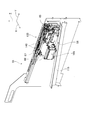
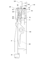
- the cutting device 65 constituting the tape feeder 55 is disposed on the front side of the feeding device 60 (that is, the downstream side in the feeding direction of the taped component 135), and includes a fixing member 70, a rotating member 80, and a roller. 85. Then, the cutting device 65 cuts the lead 142 and the carrier tape 145 taped to the carrier tape 145 to separate the radial component 140 from the carrier tape 145 and to hold the separated radial component 140 at a predetermined position. To do. Therefore, the cutting device 65 functions as a gripping device in the present invention. The specific configuration of the cutting device 65 will be described in detail later with reference to the drawings.
- the driving device 105 constituting the tape feeder 55 functions as a driving source for feeding the taped component 135 by the feeding device 60 and separating / holding the radial component 140 by the cutting device 65.
- the plate cam 106 and the cylinder 110 (see FIG. 11) and the like. including.
- the transmission rod in the drive device is disposed below the delivery device 60 and is held by the feeder main body 56 so as to be slidable in the front-rear direction in a state parallel to the transmission rod in the delivery device 60.
- the stopper in the driving device 105 is fitted on the outer peripheral surface of the transmission rod in the driving device 105. The stopper extends upward, and an upper end portion of the stopper is located in front of the contact block 63 constituting the delivery device 60.
- the contact block 63 biased forward by the elastic force of the spring comes into contact with the stopper of the drive device 105, so that the contact block 63 moves forward (i.e., The movement of the holding unit 61 to the front) is restricted by the stopper of the driving device 105.
- the plate cam 106 is formed in a plate shape extending in the front-rear direction, and includes a first portion 107 having a predetermined thickness, a second portion 108 having a thickness greater than the first portion 107, a first portion 107, and a second portion. And a third portion 109 for connecting the portion 108 with a smooth surface.
- the plate cam 106 is disposed such that the first portion 107 is located on the front side of the tape feeder 55 and the second portion 108 is located on the rear side of the tape feeder 55.
- a transmission rod in the driving device 105 is attached. Accordingly, the plate cam 106 is configured to be movable in the front-rear direction in conjunction with the transmission rod of the driving device 105.
- the plate cam 106 extends downward from the cutting device 65, and one surface of the plate cam 106 faces the roller 85 of the cutting device 65.
- the rotation member 80 of the cutting device 65 is urged by an elastic member (not shown) in a direction in which the roller 85 approaches the plate cam 106, the cutting device 80 is placed on one surface of the plate cam 106.
- a roller 85 constituting 65 is in close contact.
- the cylinder 110 is connected to the rear end portion of the transmission rod in the drive device 105 and is driven based on a control command of a controller 121 (see FIG. 11) constituting the control device 120.
- a controller 121 constituting the control device 120.
- the transmission rod of the driving device 105 slides in the front-rear direction in accordance with the operation of the cylinder 110, so that the plate cam 106 can also be moved in the front-rear direction (see FIGS. 8 to 10).
- the tape discharge path 115 is disposed below the feeder main body 56 so as to extend in the front-rear direction, and the carrier tape in a state where the radial part 140 is separated from the taped part 135 by the cutting device 65.
- 145 (hereinafter referred to as “exhaust tape”) is a discharge path for guiding the tape feeder 55 to the rear side of the tape feeder 55 and discharging the tape feeder 55 to the outside. Since the tape discharge path 115 is inclined so as to be positioned downward toward the rear side of the tape feeder 55, the discharged tape including the cut lead 142 is discharged to the outside of the tape feeder 55 by its own weight. be able to.
- the fixing device 70 includes a fixing member 70, a rotating member 80, and a roller 85.
- the fixing member 70 and the rotating member 80 sandwich the taped part 135 fed by the feeding device 60 on the downstream side in the feeding direction of the taped part 135, and X It is arranged side by side in the direction.
- the fixing member 70 is fixed in a state of being opposed to the surface on one side of the taped component 135, and includes a fixed-side cutter holding portion 71 as shown in FIG.
- the protrusion part 72 which protrudes toward the taped component 135 is formed in the upper end part of the stationary-side cutter holding
- the surface facing the tape-ized component 135 of the said protrusion 72 is fixed side holding
- a surface 73 is formed.
- the fixed-side gripping surface 73 is configured by a flat surface extending in the vertical direction and the front-rear direction of the tape feeder 55, and a fixed-side lead cutter 75 is provided at the lower edge of the fixed-side gripping surface 73. It is arranged.
- a fixed-side tape cutter 76 is disposed on the front side surface of the upper portion of the fixed-side cutter holding portion 71.
- the rotating member 80 is disposed to be rotatable about the shaft 100 with respect to the fixing member 70 in a state of being opposed to the surface on the other side of the taped component 135.
- the rotation-side cutter holding part 82, the lead holding part 90, and the lead contact member 95 are configured.
- the rotating main body 81 is disposed in a posture extending in the vertical direction, and is rotatably supported with respect to the fixed member 70 by a shaft 100 disposed so as to extend in the Y direction.
- a roller 85 is rotatably held by a shaft (not shown) extending in the vertical direction at the lower part of the rotating main body 81.
- the rotation-side cutter holding portion 82 is fixed to the upper end portion of the rotation main body portion 81 with the tip portion facing the taped component 135.
- a rotation-side lead cutter 83 is disposed at the tip of the rotation-side cutter holding portion 82.
- the rotation-side lead cutter 83 faces the fixed-side lead cutter 75 of the fixing member 70 with the lead 142 taped to the carrier tape 145 of the taped component 135 being sandwiched therebetween. Therefore, the rotation-side lead cutter 83 can cut the two leads 142 extending from the radial component 140 by cooperating with the fixed-side lead cutter 75 of the fixing member 70 when the rotation member 80 rotates. .
- a rotation-side tape cutter 84 is disposed on the front side surface of the rotation-side cutter holding portion 82.
- the rotation-side tape cutter 84 faces the fixed-side tape cutter 76 of the fixing member 70 in a state where the carrier tape 145 of the taped component 135 is sandwiched. Therefore, the rotation-side tape cutter 84 can cut the carrier tape 145 of the taped component 135 by cooperating with the fixed-side tape cutter 76 of the fixing member 70.
- the lead holding portion 90 is arranged in a posture extending in the vertical direction in a state of being overlapped with the rotation main body portion 81, and is rotated with respect to the fixing member 70 by the shaft 100. It is supported movably. Note that the lead holding portion 90 is biased toward the rotating main body portion 81 by an elastic member (not shown). For this reason, the lead holding part 90 rotates together with the rotation main body part 81.
- a lead contact member 95 is detachably attached to the upper end surface of the lead holding portion 90.
- the lead contact member 95 is configured to include a rotation-side grip surface 96, a positioning piece 97, and an attachment surface 99, and the attachment surface 99 comes into contact with the upper end surface of the lead holding portion 90. It is attached in this way.
- the lead abutting member 95 is attached so that the end portion on the fixing member 70 side protrudes from the upper end surface of the lead holding portion 90 to the fixing member 70, and the lead abutting member 95 is fixed to the rotation side cutter holding portion 82. It is located above the side lead cutter 83.
- a plurality of types of lead contact members 95 are attached to the upper end surface of the lead holding portion 90.
- the plurality of types of lead abutting members 95 have different configurations of the rotation-side gripping surface 96 and the positioning piece 97 according to the wire diameter of the lead 142 in the radial component 140 and the like.
- the lead contact member 95 may be used as a general term for a plurality of types of lead contact members.
- the rotation-side gripping surface 96 is constituted by an end surface of the lead contact member 95 on the fixing member 70 side, and is a tape positioned between the fixing member 70 and the rotation member. Opposite to the component 135. That is, the rotation-side gripping surface 96 faces the fixed-side gripping surface 73 of the fixing member 70 with the lead 142 taped to the carrier tape 145 of the taped component 135 interposed therebetween. The rotation-side grip surface 96 is located closer to the taped component 135 than the cutting edge of the rotation-side lead cutter 83 in a state where the lead holding portion 90 is rotated together with the rotation main body portion 81.
- the rotation-side gripping surface 96 is configured as a flat surface that is inclined with respect to the mounting surface 99 of the lead contact member 95 so as to form a predetermined inclination angle. It is determined according to the diameter. Specifically, the inclination angle of the rotation-side gripping surface 96 is determined as an angle that is parallel to the fixed-side gripping surface 73 when gripping the lead 142 with the fixed-side gripping surface 73.
- a positioning piece 97 is formed on the upper end surface of the lead contact member 95 so as to protrude from the rotating gripping surface 96 of the lead contact member 95 to the taped component 135 side. As shown in FIG. 5, a pair of notches 98 are formed at the edge of the positioning piece 97. The pair of notches 98 are formed according to the wire diameter and pitch of the pair of leads 142 in the radial part 140 of the taped part 135.
- the cutting device 65 cuts the lead 142 and the carrier tape 145 taped to the carrier tape 145 as the rotating member 80 rotates, and separates the radial component 140 from the carrier tape 145.
- the carrier tape 145 is placed inside the pair of notches 98 of the positioning piece 97.
- a pair of taped leads 142 enters.
- the taped radial component 140 is positioned between the fixing member 70 and the rotating member 80.
- the pair of leads 142 is sandwiched between the rotation-side grip surface 96 of the rotation member 80 and the fixed-side grip surface 73 of the fixing member 70.
- the radial component 140 having the pair of leads 142 is held at a predetermined position.
- the lead holding portion 90 is further prevented from rotating by contact of the rotating side holding surface 96 with the fixed holding surface 73 via the lead 142.
- the rotation main body 81 further rotates.
- the rotation-side lead cutter 83 of the rotation-side cutter holding portion 82 approaches the fixed-side lead cutter 75 of the fixing member 70 and is held between the rotation-side holding surface 96 and the fixed-side holding surface 73.
- the pair of leads 142 is cut by the rotation-side lead cutter 83 and the fixed-side lead cutter 75.
- the rotation-side tape cutter 84 of the rotation-side cutter holding portion 82 approaches the fixed-side tape cutter 76 of the fixing member 70, so that the carrier tape 145 of the taped component 135 rotates with the fixed-side tape cutter 76. It is cut by the side tape cutter 84.
- the radial component 140 is separated from the carrier tape 145, and the radial component 140 is supplied at the position positioned by the positioning piece 97. That is, the lead 142 of the radial component 140 is positioned by the notch 98 of the positioning piece 97 and is sandwiched between the rotation-side gripping surface 96 and the fixed-side gripping surface 73 so that it is supplied without falling down.
- the operation of the cylinder 110 causes the delivery device 60 and the cutting device 65 to operate in an integrated manner, so that the taped component 135 is delivered and the taped component 135 is removed.
- the radial parts 140 can be separated.
- the contact block 63 of the delivery device 60 is slid forward while being urged forward by the elastic force of the spring.
- the holding unit 61 that holds the claw member 62 also slides forward together with the contact block 63.
- the claw member 62 is engaged with the feed hole 146 of the taped part 135 when sliding forward by a predetermined amount, so that the claw member 62 slides forward,
- the taped component 135 is fed forward by a predetermined amount.
- the plate cam 106 also slides forward by the operation of the cylinder 110 in this case.
- the position of the plate cam 106 before the operation of the cylinder 110 is referred to as a neutral position, and the roller 85 is in close contact with the first portion 107 with respect to the plate cam 106 at the neutral position.
- the feeding device 60 The state where the claw member 62 is engaged with the feed hole 146 of the carrier tape 145 is maintained, and the engagement of the claw member 62 with the feed hole 146 is released at a predetermined timing. Thereby, the taped component 135 is stopped when a predetermined amount is sent to the front side of the tape feeder 55. During this time, since the contact surface with the roller 85 remains the first portion 107 of the plate cam 106 (see FIG. 8), the rotating member 80 of the cutting device 65 does not rotate, and the radial component 140 is not rotated. Is not gripped / separated.
- the plate cam 106 is further slid forward from the state shown in FIG. 8, and the contact surface of the roller 85 with respect to the plate cam 106 is moved from the first portion 107 to the third portion 109 (see FIG. 9). ). At this time, the contact surface with the roller 85 moves from the first portion 107 to the third portion 109, so that the roller 85 moves in a direction away from the plate cam 106. Thereby, in the cutting device 65, the rotation member 80 rotates about the shaft 100, and the upper end portion thereof approaches the taped component 135.
- the plate cam 106 is further slid forward from the state shown in FIG. 9, and the contact surface of the roller 85 with respect to the plate cam 106 is moved from the third portion 109 to the second portion 108 (FIG. 10).
- the roller 85 further moves in a direction away from the plate cam 106.
- the pair of leads 142 taped to the carrier tape 145 rotate with the fixed gripping surface 73.
- the pair of leads 142 is cut by the fixed-side lead cutter 75 and the rotating-side lead cutter 83 while being sandwiched by the side gripping surface 96.
- the carrier tape 145 of the taped component 135 is cut by the fixed side tape cutter 76 and the rotating side tape cutter 84. That is, while the delivery of the taped part 135 by the delivery device 60 is stopped, the pair of leads 142 taped to the carrier tape 145 are held in the cutting device 65, and the pair of leads 142 and the carrier tape 145 are retained. Disconnected.
- the plate cam 106 slides to the position shown in FIG. 10, the plate cam 106 is slid backward by the operation of the cylinder 110 and returned to the neutral position. At this time, the adhesion of the roller 85 to the plate cam 106 is maintained by an elastic force. For this reason, in the cutting device 65, the rotating member 80 rotates in a direction in which the upper end portion is separated from the taped part 135.
- the contact block 63 slides backward against the elastic force of the spring by the operation of the cylinder 110, and the holding unit 61 is also slid backward together with the contact block 63.
- the holding unit 61 is slid to the rear end position, the claw member 62 is engaged with the feed hole 146 of the taped component 135.
- the operation of the cylinder 110 causes the delivery device 60 and the cutting device 65 to operate in an integrated manner. That is, the cylinder 110 is shared as a drive source for the delivery device 60 and the cutting device 65. As a result, the number of drive sources can be minimized, and the space for arranging the drive sources, the cost required for the drive sources, and the like can be suppressed.
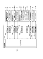
- the control system of the component mounting apparatus 10 according to the present embodiment includes the control device 120 that performs various controls for mounting components such as the radial component 140 on the circuit substrate 130.
- the control device 120 includes a controller 121, a plurality of drive circuits 122, and an image processing device 123.
- the plurality of drive circuits 122 include the transport device 21, the clamp device 22, the work head 26, the work head 27, the work head moving device 29, the tray-type component supply device 51, the cylinder 110, and the bulk component supply. It is connected to the device 50.
- the controller 121 includes a CPU, a ROM, a RAM, and the like, and is configured mainly with a computer.
- the controller 121 is connected to a plurality of drive circuits 122. Thereby, the operations of the substrate conveyance holding device 20, the component mounting device 25, the component supply device 50, the component supply device 45, and the like are controlled by the controller 121.
- the controller 121 is also connected to the image processing device 123.
- the image processing device 123 is a device for performing image processing on image data obtained by the mark camera 35 and the parts camera 40. Therefore, the controller 121 can acquire various types of information by performing image processing on the image data captured by the mark camera 35 and the parts camera 40.
- the lead abutting member 95 corresponding to the wire diameter of the lead 142 in the radial component 140 can be attached to the upper end surface of the lead holding portion 90, and thus the fixing member When the lead 142 of the radial component 140 is sandwiched and gripped by the 70 and the rotating member 80, the radial component 140 can be gripped more firmly.
- the first lead contact member 95a is one of the above-described plural types of lead contact members 95, and corresponds to the radial component 140 having the lead 142 having the first lead wire diameter Da.
- the rotation-side grip surface 96 of the first lead contact member 95a is constituted by the end surface of the first lead contact member 95a on the fixing member 70 side, and the lead taped on the carrier tape 145 of the taped component 135. In a state where 142 is sandwiched, the fixing member 70 faces the fixed-side gripping surface 73.
- the rotation-side grip surface 96 of the first lead contact member 95a is configured as a flat surface that is inclined with respect to the mounting surface 99, and has a first inclination angle ⁇ a. ing.
- the first inclination angle ⁇ a is a relative diameter between the shaft 100 and the diameter of the lead 142 in the radial component 140 (that is, the first lead wire diameter Da), the rotation-side grip surface 96 when the lead 142 is clamped, and the shaft 100.
- the first lead wire diameter Da the diameter of the lead 142 in the radial component 140
- the rotation-side grip surface 96 when the lead 142 is clamped and the shaft 100.
- a pair of notches 98 is formed in the positioning piece 97 of the first lead abutting member 95a, and the pair of notches 98 is a wire diameter of the pair of leads 142 in the radial component 140 (ie, It is formed according to the first lead wire diameter Da) and the pitch.
- the rotation-side grip surface 96 of the first lead contact member 95 a vertically cuts the rotation-side grip surface 96 along the lead 142. Will be in line contact.
- the fixed-side gripping surface 73 of the fixing member 70 contacts the lead 142 at a position facing the contact portion of the lead 142 on the rotation-side gripping surface 96 through the center of the lead 142. Along the line, line contact is made so as to cut the fixed-side gripping surface 73 vertically.
- the first lead contact member 95 a to grip the radial component 140 having the lead 142 having the first lead wire diameter Da, the fixed member 70 side and the rotating member In any of the 80 sides, a sufficient contact area with the lead 142 can be secured, and the pressure when the lead 142 is sandwiched can be applied substantially uniformly over a wide range.
- the posture of the radial component 140 having the lead 142 having the first lead wire diameter Da can be easily achieved. It can be firmly held without changing.
- the second lead contact member 95b is one of the above-described plural types of lead contact members 95, and corresponds to the radial component 140 having the lead 142 having the second lead wire diameter Db.
- the rotation-side grip surface 96 of the second lead contact member 95b is constituted by the end surface of the second lead contact member 95b on the fixing member 70 side, and the lead taped on the carrier tape 145 of the taped component 135. In a state where 142 is sandwiched, the fixing member 70 faces the fixed-side gripping surface 73.
- the rotation-side gripping surface 96 of the second lead contact member 95b is configured as a flat surface inclined with respect to the mounting surface 99, and is smaller than the first inclination angle ⁇ a.
- the second inclination angle ⁇ b is used.
- the second inclination angle ⁇ b is relative to the shaft 100 and the diameter of the lead 142 in the radial component 140 (that is, the second lead wire diameter Db), the rotation-side gripping surface 96 when the lead 142 is clamped, and the shaft 100.
- it is determined by the positional relationship and the like, and is parallel to the fixed-side holding surface 73 when holding the lead 142 having the second lead wire diameter Db with the fixed-side holding surface 73. It is determined to do.
- a pair of notches 98 is formed in the positioning piece 97 of the second lead abutting member 95b, and the pair of notches 98 has a wire diameter (that is, a pair of leads 142 in the radial component 140 (that is, The second lead wire diameter Db) and the pitch are formed.
- the rotation-side grip surface 96 of the second lead contact member 95 b vertically cuts the rotation-side grip surface 96 along the lead 142. Will be in line contact.
- the fixed-side gripping surface 73 of the fixing member 70 contacts the lead 142 at a position facing the contact portion of the lead 142 on the rotation-side gripping surface 96 through the center of the lead 142. Along the line, line contact is made so as to cut the fixed-side gripping surface 73 vertically.
- the radial component 140 having the lead 142 having the second lead wire diameter Db is gripped by using the second lead abutting member 95 b, so that the fixing member 70 side and the rotating member are arranged.
- a sufficient contact area with the lead 142 can be secured, and the pressure when the lead 142 is sandwiched can be applied substantially uniformly over a wide range.
- the posture of the radial component 140 having the lead 142 having the second lead wire diameter Db can be easily adjusted by attaching the second lead contact member 95 b to the rotating member 80. It can be firmly held without changing.
- the tape feeder 55 has the cutting device 65 that holds the lead 142 when supplying the radial component 140 having the lead 142 ( (See FIGS. 5 to 7).
- the fixing member 70 having a fixed-side gripping surface 73 at the end as a surface that contacts the one surface of the lead 142, and the fixing member 70
- the end portion has a flat rotation-side gripping surface 96 that comes into contact with the other surface of the lead 142 when gripping the lead 142 of the radial component 140.
- a rotating member 80 As shown in FIGS. 13 and 15, when the rotation-side gripping surface 96 grips the lead 142 of the radial component 140 with the fixed-side gripping surface 73 of the fixing member 70, It is inclined so as to be parallel to the fixed-side gripping surface 73.
- a fixing member having a first gripping surface at the end as a surface to be contacted from one surface side of the lead 142, a rotation member disposed so as to be rotatable with respect to the fixing member, And a rotating member having a planar second gripping surface that contacts from the other surface side at the end, and therefore, a fixed gripping surface 73 of the fixing member 70 and a rotating gripping surface of the rotating member 80 96, the lead 142 of the radial component 140 can be sandwiched and gripped.
- the rotation-side gripping surface 96 is Since it inclines so that it may become parallel, the contact area of the fixed side holding surface 73 and the rotation side holding surface 96 with respect to the lead 142 can be sufficiently secured, and the radial component 140 can be securely held.
- the lead-side grip surface 73 of the fixing member 70 grips the lead 142 with the rotation-side grip surface 96 of the rotation member 80, It has one or more parts which are in line contact with it.
- a sufficient contact area with the lead 142 can be ensured even on the fixed-side gripping surface 73 of the fixing member 70, and the rotation-side gripping surface 96 and the fixed-side gripping surface 73 are secured.
- the lead 142 can be securely held, and the radial component 140 can be firmly held without changing its posture.
- a plurality of types of lead contact members 95 including the rotation-side gripping surface 96 are attached to the end of the rotation member 80 in an exchangeable manner.
- the rotation-side gripping surface 96 of the plural types of lead contact members 95 (for example, the first lead contact member 95a and the second lead contact member 95b) is an attachment surface that contacts the upper end portion of the rotation member 80.
- the lead 142 is inclined at angles (for example, a first inclination angle ⁇ a and a second inclination angle ⁇ b) corresponding to the wire diameters (for example, the first lead wire diameter Da and the second lead wire diameter Db). (See FIGS. 12 to 15).
- the lead contact member 95 attached to the rotating member 80 is replaced with a corresponding type of lead contact.
- the radial component 140 can be reliably gripped. That is, according to the component mounting apparatus 10, by replacing the plural types of lead contact members 95 with the corresponding types of lead contact members 95, the component mounting apparatus 10 supports the radial components 140 having various lead 142 wire diameters. Thus, the radial component 140 can be securely gripped.
- the component supply device 50, the feeder-type component supply device 52, and the tape feeder 55 are examples of the component supply device in the present invention, and the cutting device 65 is an example of the gripping device in the present invention.
- the fixing member 70 is an example of a fixing member in the present invention, and the fixed-side gripping surface 73 is an example of a first gripping surface in the present invention.
- the rotation member 80 is an example of the rotation member in the present invention, and the rotation side holding surface 96 is an example of the second holding surface in the present invention.
- the lead contact member 95, the first lead contact member 95a, and the second lead contact member 95b are examples of the contact member in the present invention, and the mounting surface 99 is an example of the mounting surface in the present invention.
- the radial component 140 is an example of the lead component in the present invention, and the lead 142 is an example of the lead in the present invention.
- the fixed-side gripping surface 73 of the fixing member 70 is configured as a flat surface, but is not limited to this aspect.
- a predetermined shape is used so that two or more portions are in contact with the lead 142. It may be formed.
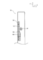
- a fixing groove 74 may be formed in each portion of the fixed-side gripping surface 73 that contacts the pair of leads 142.
- the fixed groove 74 is a groove having an isosceles cross section, and is formed so as to vertically cut the fixed-side gripping surface 73 in the vertical direction. If the fixing groove 74 is formed in this way, the lead 142 comes into line contact at two locations on the inner wall surface of the fixing groove 74, and even between the rotation-side gripping surface 96 and the lead 142. You can balance the power.
- the lead 142 is securely held between the rotation-side gripping surface 96 and the fixed-side gripping surface 73, so that the radial component 140 can be firmly fixed without changing its posture. Can be gripped.
- the rotation main body 81 and the lead holding portion 90 constituting the rotation member 80 are supported by the shaft 100 so as to be rotatable with respect to the fixed member 70. It is not limited.
- the shaft 100 is formed on another member different from the fixing member 70, and the rotation main body 81 and the lead holding portion 90 constituting the rotation member 80 are pivotally supported by the shaft 100. You can also
- the rotation-side grip surface 96 of the lead contact member 95 is fixed when the lead 142 of the radial component 140 is gripped between the rotation-side grip surface 96 and the fixed-side grip surface 73 of the fixing member 70. What is necessary is just to incline so that it may become parallel with respect to the side holding surface 73.
- the rotation-side gripping surface 96 in this case may be configured as a flat surface that is inclined with respect to the mounting surface 99 so as to form an acute angle.
- the radial component 140 has been described as the lead component.
- any component having a lead may be used.
- an axial component may be used as the lead component of the present invention.
- the cutting device 65 is cited as the gripping device that grips the lead component.
- the present invention is not limited to this mode.
- the gripping device according to the present invention only needs to be able to grip and hold the lead of the lead component between the fixing member and the rotating member, and has a function of cutting the lead 142 and the carrier tape 145 as in the above-described embodiment. You don't have to.
Landscapes
- Engineering & Computer Science (AREA)
- Manufacturing & Machinery (AREA)
- Microelectronics & Electronic Packaging (AREA)
- Supply And Installment Of Electrical Components (AREA)
Abstract
L'invention concerne un dispositif de montage de composants (10) dans lequel un dispositif d'alimentation de bande (55) comporte un dispositif de coupe (65) qui saisit un fil (142) lorsqu'un composant radial (140) comportant le fil (142) est fourni. Le dispositif de coupe (65) comprend : un élément fixe (70) comportant, au niveau d'une section d'extrémité, une surface de préhension côté fixe (73) servant de surface pour la mise en contact d'un côté de surface du fil (142), lorsque le fil (142) du composant radial (140) est saisi ; et un élément rotatif (80) qui est disposé de façon à pouvoir tourner par rapport à l'élément fixe (70), et qui comporte, au niveau d'une section d'extrémité, une surface de préhension côté rotation plane (96) servant à la mise en contact d'un autre côté de surface du fil (142), lorsque le fil (142) du composant radial (140) est saisi. La surface de préhension côté rotation (96) est inclinée de façon à être parallèle à la surface de préhension côté fixe (73) lors de la saisie du fil (142) du composant radial (140) entre celle-ci et la surface de préhension côté fixe (73) de l'élément fixe (70).
Priority Applications (2)
| Application Number | Priority Date | Filing Date | Title |
|---|---|---|---|
| JP2018510172A JP6738409B2 (ja) | 2016-04-06 | 2016-04-06 | 部品供給装置 |
| PCT/JP2016/061242 WO2017175332A1 (fr) | 2016-04-06 | 2016-04-06 | Dispositif d'alimentation en composants |
Applications Claiming Priority (1)
| Application Number | Priority Date | Filing Date | Title |
|---|---|---|---|
| PCT/JP2016/061242 WO2017175332A1 (fr) | 2016-04-06 | 2016-04-06 | Dispositif d'alimentation en composants |
Publications (1)
| Publication Number | Publication Date |
|---|---|
| WO2017175332A1 true WO2017175332A1 (fr) | 2017-10-12 |
Family
ID=60000341
Family Applications (1)
| Application Number | Title | Priority Date | Filing Date |
|---|---|---|---|
| PCT/JP2016/061242 Ceased WO2017175332A1 (fr) | 2016-04-06 | 2016-04-06 | Dispositif d'alimentation en composants |
Country Status (2)
| Country | Link |
|---|---|
| JP (1) | JP6738409B2 (fr) |
| WO (1) | WO2017175332A1 (fr) |
Cited By (1)
| Publication number | Priority date | Publication date | Assignee | Title |
|---|---|---|---|---|
| CN111886941A (zh) * | 2018-04-10 | 2020-11-03 | 株式会社富士 | 带式供料器 |
Citations (3)
| Publication number | Priority date | Publication date | Assignee | Title |
|---|---|---|---|---|
| JPS60109794U (ja) * | 1983-12-23 | 1985-07-25 | ホ−プ精機株式会社 | チヤツク機構 |
| JPH0362788U (fr) * | 1989-10-23 | 1991-06-19 | ||
| WO2015136600A1 (fr) * | 2014-03-10 | 2015-09-17 | 富士機械製造株式会社 | Dispositif d'alimentation de bande |
-
2016
- 2016-04-06 WO PCT/JP2016/061242 patent/WO2017175332A1/fr not_active Ceased
- 2016-04-06 JP JP2018510172A patent/JP6738409B2/ja active Active
Patent Citations (3)
| Publication number | Priority date | Publication date | Assignee | Title |
|---|---|---|---|---|
| JPS60109794U (ja) * | 1983-12-23 | 1985-07-25 | ホ−プ精機株式会社 | チヤツク機構 |
| JPH0362788U (fr) * | 1989-10-23 | 1991-06-19 | ||
| WO2015136600A1 (fr) * | 2014-03-10 | 2015-09-17 | 富士機械製造株式会社 | Dispositif d'alimentation de bande |
Cited By (3)
| Publication number | Priority date | Publication date | Assignee | Title |
|---|---|---|---|---|
| CN111886941A (zh) * | 2018-04-10 | 2020-11-03 | 株式会社富士 | 带式供料器 |
| EP3780927A4 (fr) * | 2018-04-10 | 2021-04-07 | Fuji Corporation | Dispositif d'alimentation de bande |
| CN111886941B (zh) * | 2018-04-10 | 2022-07-22 | 株式会社富士 | 带式供料器 |
Also Published As
| Publication number | Publication date |
|---|---|
| JPWO2017175332A1 (ja) | 2019-02-14 |
| JP6738409B2 (ja) | 2020-08-12 |
Similar Documents
| Publication | Publication Date | Title |
|---|---|---|
| US10342170B2 (en) | Electronic component supply apparatus, reel apparatus, tape processing apparatus, and method for resupplying component stored tape | |
| JP6554440B2 (ja) | 部品供給装置、部品供給方法および表面実装機 | |
| US10390470B2 (en) | Component supply device, component mounter, and component-mounted board manufacturing method | |
| JPWO2018198279A1 (ja) | リード線矯正装置 | |
| WO2016129069A1 (fr) | Dispositif d'introduction de composants | |
| WO2013179532A1 (fr) | Attache pour une installation de ligne d'alimentation et procédé pour une installation de ligne d'alimentation | |
| WO2016135909A1 (fr) | Dispositif de fourniture de composants et dispositif de montage | |
| WO2017175332A1 (fr) | Dispositif d'alimentation en composants | |
| JP7488159B2 (ja) | テープフィーダ、および部品実装装置 | |
| JP6940588B2 (ja) | 作業機、および装着方法 | |
| US20220161310A1 (en) | Bending device, component supply device, and bending method | |
| JPWO2018146740A1 (ja) | 作業機 | |
| JP2019140384A (ja) | 押さえ機能を備える部品実装機 | |
| JP7523025B2 (ja) | 切断装置、部品装着システム及びテープ切断方法 | |
| JP6765383B2 (ja) | テープフィーダ | |
| CN108605429B (zh) | 元件供给装置、元件供给方法及表面安装机 | |
| JPWO2018131139A1 (ja) | 部品実装装置 | |
| WO2017081724A1 (fr) | Appareil de cintrage | |
| JP7554274B2 (ja) | アキシャル部品供給装置、及び供給方法 | |
| JP7411841B2 (ja) | 切断・屈曲装置 | |
| JP7232848B2 (ja) | テープフィーダ | |
| CN105830553A (zh) | 对基板作业装置 | |
| US12167539B2 (en) | Tape feeder | |
| JP2020080438A (ja) | テープフィーダ、および部品実装装置 | |
| JP2019134191A (ja) | 部品供給装置 |
Legal Events
| Date | Code | Title | Description |
|---|---|---|---|
| WWE | Wipo information: entry into national phase |
Ref document number: 2018510172 Country of ref document: JP |
|
| NENP | Non-entry into the national phase |
Ref country code: DE |
|
| 121 | Ep: the epo has been informed by wipo that ep was designated in this application |
Ref document number: 16897890 Country of ref document: EP Kind code of ref document: A1 |
|
| 122 | Ep: pct application non-entry in european phase |
Ref document number: 16897890 Country of ref document: EP Kind code of ref document: A1 |