WO2017175362A1 - Batterie assemblée en forme de plaque - Google Patents
Batterie assemblée en forme de plaque Download PDFInfo
- Publication number
- WO2017175362A1 WO2017175362A1 PCT/JP2016/061447 JP2016061447W WO2017175362A1 WO 2017175362 A1 WO2017175362 A1 WO 2017175362A1 JP 2016061447 W JP2016061447 W JP 2016061447W WO 2017175362 A1 WO2017175362 A1 WO 2017175362A1
- Authority
- WO
- WIPO (PCT)
- Prior art keywords
- negative electrode
- bus bar
- positive electrode
- assembled battery
- plate
- Prior art date
- Legal status (The legal status is an assumption and is not a legal conclusion. Google has not performed a legal analysis and makes no representation as to the accuracy of the status listed.)
- Ceased
Links
Images





Classifications
-
- H—ELECTRICITY
- H01—ELECTRIC ELEMENTS
- H01M—PROCESSES OR MEANS, e.g. BATTERIES, FOR THE DIRECT CONVERSION OF CHEMICAL ENERGY INTO ELECTRICAL ENERGY
- H01M50/00—Constructional details or processes of manufacture of the non-active parts of electrochemical cells other than fuel cells, e.g. hybrid cells
- H01M50/20—Mountings; Secondary casings or frames; Racks, modules or packs; Suspension devices; Shock absorbers; Transport or carrying devices; Holders
- H01M50/218—Mountings; Secondary casings or frames; Racks, modules or packs; Suspension devices; Shock absorbers; Transport or carrying devices; Holders characterised by the material
- H01M50/22—Mountings; Secondary casings or frames; Racks, modules or packs; Suspension devices; Shock absorbers; Transport or carrying devices; Holders characterised by the material of the casings or racks
- H01M50/231—Mountings; Secondary casings or frames; Racks, modules or packs; Suspension devices; Shock absorbers; Transport or carrying devices; Holders characterised by the material of the casings or racks having a layered structure
-
- H—ELECTRICITY
- H01—ELECTRIC ELEMENTS
- H01M—PROCESSES OR MEANS, e.g. BATTERIES, FOR THE DIRECT CONVERSION OF CHEMICAL ENERGY INTO ELECTRICAL ENERGY
- H01M50/00—Constructional details or processes of manufacture of the non-active parts of electrochemical cells other than fuel cells, e.g. hybrid cells
- H01M50/10—Primary casings; Jackets or wrappings
- H01M50/102—Primary casings; Jackets or wrappings characterised by their shape or physical structure
- H01M50/103—Primary casings; Jackets or wrappings characterised by their shape or physical structure prismatic or rectangular
-
- H—ELECTRICITY
- H01—ELECTRIC ELEMENTS
- H01M—PROCESSES OR MEANS, e.g. BATTERIES, FOR THE DIRECT CONVERSION OF CHEMICAL ENERGY INTO ELECTRICAL ENERGY
- H01M50/00—Constructional details or processes of manufacture of the non-active parts of electrochemical cells other than fuel cells, e.g. hybrid cells
- H01M50/20—Mountings; Secondary casings or frames; Racks, modules or packs; Suspension devices; Shock absorbers; Transport or carrying devices; Holders
- H01M50/204—Racks, modules or packs for multiple batteries or multiple cells
- H01M50/207—Racks, modules or packs for multiple batteries or multiple cells characterised by their shape
- H01M50/209—Racks, modules or packs for multiple batteries or multiple cells characterised by their shape adapted for prismatic or rectangular cells
-
- H—ELECTRICITY
- H01—ELECTRIC ELEMENTS
- H01M—PROCESSES OR MEANS, e.g. BATTERIES, FOR THE DIRECT CONVERSION OF CHEMICAL ENERGY INTO ELECTRICAL ENERGY
- H01M50/00—Constructional details or processes of manufacture of the non-active parts of electrochemical cells other than fuel cells, e.g. hybrid cells
- H01M50/20—Mountings; Secondary casings or frames; Racks, modules or packs; Suspension devices; Shock absorbers; Transport or carrying devices; Holders
- H01M50/218—Mountings; Secondary casings or frames; Racks, modules or packs; Suspension devices; Shock absorbers; Transport or carrying devices; Holders characterised by the material
- H01M50/22—Mountings; Secondary casings or frames; Racks, modules or packs; Suspension devices; Shock absorbers; Transport or carrying devices; Holders characterised by the material of the casings or racks
- H01M50/222—Inorganic material
- H01M50/224—Metals
-
- H—ELECTRICITY
- H01—ELECTRIC ELEMENTS
- H01M—PROCESSES OR MEANS, e.g. BATTERIES, FOR THE DIRECT CONVERSION OF CHEMICAL ENERGY INTO ELECTRICAL ENERGY
- H01M50/00—Constructional details or processes of manufacture of the non-active parts of electrochemical cells other than fuel cells, e.g. hybrid cells
- H01M50/20—Mountings; Secondary casings or frames; Racks, modules or packs; Suspension devices; Shock absorbers; Transport or carrying devices; Holders
- H01M50/218—Mountings; Secondary casings or frames; Racks, modules or packs; Suspension devices; Shock absorbers; Transport or carrying devices; Holders characterised by the material
- H01M50/22—Mountings; Secondary casings or frames; Racks, modules or packs; Suspension devices; Shock absorbers; Transport or carrying devices; Holders characterised by the material of the casings or racks
- H01M50/227—Organic material
-
- H—ELECTRICITY
- H01—ELECTRIC ELEMENTS
- H01M—PROCESSES OR MEANS, e.g. BATTERIES, FOR THE DIRECT CONVERSION OF CHEMICAL ENERGY INTO ELECTRICAL ENERGY
- H01M50/00—Constructional details or processes of manufacture of the non-active parts of electrochemical cells other than fuel cells, e.g. hybrid cells
- H01M50/20—Mountings; Secondary casings or frames; Racks, modules or packs; Suspension devices; Shock absorbers; Transport or carrying devices; Holders
- H01M50/262—Mountings; Secondary casings or frames; Racks, modules or packs; Suspension devices; Shock absorbers; Transport or carrying devices; Holders with fastening means, e.g. locks
-
- H—ELECTRICITY
- H01—ELECTRIC ELEMENTS
- H01M—PROCESSES OR MEANS, e.g. BATTERIES, FOR THE DIRECT CONVERSION OF CHEMICAL ENERGY INTO ELECTRICAL ENERGY
- H01M50/00—Constructional details or processes of manufacture of the non-active parts of electrochemical cells other than fuel cells, e.g. hybrid cells
- H01M50/50—Current conducting connections for cells or batteries
-
- Y—GENERAL TAGGING OF NEW TECHNOLOGICAL DEVELOPMENTS; GENERAL TAGGING OF CROSS-SECTIONAL TECHNOLOGIES SPANNING OVER SEVERAL SECTIONS OF THE IPC; TECHNICAL SUBJECTS COVERED BY FORMER USPC CROSS-REFERENCE ART COLLECTIONS [XRACs] AND DIGESTS
- Y02—TECHNOLOGIES OR APPLICATIONS FOR MITIGATION OR ADAPTATION AGAINST CLIMATE CHANGE
- Y02E—REDUCTION OF GREENHOUSE GAS [GHG] EMISSIONS, RELATED TO ENERGY GENERATION, TRANSMISSION OR DISTRIBUTION
- Y02E60/00—Enabling technologies; Technologies with a potential or indirect contribution to GHG emissions mitigation
- Y02E60/10—Energy storage using batteries
Definitions
- the present invention relates to an assembled battery formed by combining a plurality of single-cell secondary batteries.
- Patent Document 1 a plurality of battery power generation elements each configured by stacking a positive electrode, a negative electrode, and a separator are respectively stored in a plurality of battery power generation element storage portions of a battery case, and these battery power generation elements are connected to a bus bar. After that, an assembled battery configured by a simple manufacturing process of sealing a battery case with a cover plate is described.
- the material of the bus bar of the assembled battery of Patent Document 1 is a conductive metal such as aluminum or nickel
- the material of the terminal portion of the positive electrode is a conductive metal such as aluminum, aluminum alloy, SUS, or titanium.
- the material of the negative electrode terminal portion is a conductive metal such as copper, nickel, silver, or SUS, different types of materials are used unless the bus bar, the positive electrode terminal portion, and the negative electrode terminal portion are all made of the same material. There has been a problem that, when metals are connected to each other, electric corrosion (electrochemical corrosion) due to moisture in the air occurs.
- Patent Document 2 discloses a bus bar for terminal connection used for a battery in which a plus terminal and a minus terminal are formed of different metals, and the same metal as the plus terminal of the battery.
- a positive electrode connecting portion formed and connectable to the positive terminal; and a negative electrode connecting portion formed of the same metal as the negative terminal of the battery and connectable to the negative terminal.
- a bus bar is described in which and are integrated by a metallic bond. This “metallic bond” forms a bonded interface in which different kinds of metals to be bonded are in close contact with each other at the metal structure level.
- the conductivity and mechanical bond strength are set to “values suitable for practical use as a bus bar”. It is described as saying that it has been raised.
- the present invention has been made in view of such conventional problems, and an object of the present invention is a plate that can be easily manufactured without using a large-scale facility and that prevents electric corrosion. It is to provide a battery pack. In addition to the above object, another object of the present invention is to provide a plate-shaped assembled battery that can be easily assembled equal to or more than the conventional one and that maintains high quality.
- the present inventor first electrically connected a copper negative electrode bus bar and an aluminum positive electrode bus bar to each other by caulking or bolt fastening.
- At least a part of the connection surface is configured to be disposed outside the plurality of storage portions, and at least a part of the connection part of the negative electrode bus bar and the connection part of the positive electrode bus bar in the direction along the connection surface.
- the outer periphery is seamlessly covered with the inner wall of the battery pack case over the entire circumference, and it is easy to manufacture without using large-scale equipment by blocking the inflow of moisture in the air to the connection surface. And it discovered that electric corrosion could be prevented.
- the present inventor attaches a caulking nut to at least one of the negative electrode bus bar and the positive electrode bus bar, injects the electrolytic solution from the hole, and then seals the hole with a screw, so that it is as easy as or more than the conventional one.
- the present inventors have found that they can be assembled and can maintain high quality, and have arrived at the present invention.
- the present invention electrically insulates a negative electrode element having a negative electrode battery active material and a negative electrode current collector, a positive electrode element having a positive electrode battery active material and a positive electrode current collector, and the negative electrode element and the positive electrode element.
- a plurality of unit cell elements each having a separator, and a flat plate assembly made of an insulating material, each having a same number of storage units as the plurality of unit cell elements, each storing a plurality of unit cell elements in each storage unit.
- a battery case a long negative electrode bus bar made of a conductive material, integrated with the assembled battery case to connect a plurality of single cell elements in series, and an integrated battery case integrally connected to the negative electrode bus bar
- a long positive electrode bus bar made of a conductive material different from the negative electrode bus bar
- a sealing plate for hermetically sealing a plurality of storage portions of the assembled battery case into which the electrolyte solution has been injected.
- Each of the cell elements of At least a part is in a state exposed in each storage portion, and the negative electrode bus bar is disposed in one end portion, and the unit cell in the storage portion in which one unit cell element connected in series is stored.
- the negative electrode current collector connected to the element is electrically connected to the negative electrode stacking connection part, and the negative electrode connecting part is arranged at the other end, and the positive electrode bus bar is arranged at one end and in series
- a positive electrode stacking connection part electrically connected to a positive electrode current collecting part provided in the single cell element in a storage part in which the other single battery element to be connected to is connected, and a positive electrode connection disposed at the other end part
- the negative electrode connecting portion and the positive electrode connecting portion are electrically connected to each other by caulking or bolt fastening, and at least a part of the electrical connection surface between the negative electrode connecting portion and the positive electrode connecting portion is any It is configured to be arranged outside the plurality of storage units There is provided a Jo battery pack.
- the assembled battery case covers the entire circumference of at least a part of the whole of the negative electrode connecting portion and the positive electrode connecting portion that are electrically connected to each other in the direction along the connection surface. It is preferable to have a connecting part fixing wall. Furthermore, it is preferable to include a sealant applied to the interface between the negative electrode bus bar and the connecting portion fixing wall and the interface between the positive electrode bus bar and the connecting portion fixing wall.
- a negative electrode terminal plate and a positive electrode terminal plate configured integrally with an assembled battery case for taking out electric power from the plate-shaped assembled battery, the negative electrode bus bar or the negative electrode terminal plate and the positive electrode bus bar arranged in the same storage unit, At least one of the positive electrode terminal plates preferably has a liquid injection hole for injecting an electrolytic solution.
- the liquid injection hole preferably has a liquid injection auxiliary member fixed to the liquid injection hole by caulking in order to assist sealing of the liquid injection hole. It is preferable that the negative electrode bus bar and the positive electrode bus bar have a plate shape bent stepwise. It is preferable that the negative electrode bus bar and the positive electrode bus bar have a plate shape bent in a U shape.
- the width of the bent portion of the negative electrode bus bar and the positive electrode bus bar is preferably equal to or less than the straight portion.
- the assembled battery case has a negative electrode bus bar protection part for covering one surface of a part of the negative electrode bus bar, and a positive electrode bus bar protection part for covering a part of one surface of the positive electrode bus bar.
- the thickness of the part and the positive electrode bus bar protection part is preferably 5 mm or less.
- the present invention can be easily manufactured without using a large-scale facility, and electric corrosion can be prevented. Further, according to the present invention, in addition to the above effects, it can be easily assembled equal to or higher than the conventional one and high quality can be maintained.
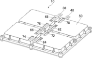
- FIG. 1 is a perspective view showing a plate-shaped assembled battery according to a first embodiment of the present invention from the sealing plate side.
- FIG. 2 is a perspective view showing the plate assembled battery of FIG. 1 from the opposite side of the sealing plate.
- FIG. 3 is a perspective view showing a state where the sealing plate and the single cell element are removed from the plate-shaped assembled battery of FIG.
- FIG. 4 is a side view schematically showing a stacked state of unit cell elements of the plate-like assembled battery of FIG.
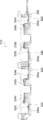
- FIG. 5 is a plan view showing a state in which the sealing plate is removed from the plate-shaped assembled battery of FIG. 6 is a cross-sectional view of the plate assembled battery of FIG. 1 cut along line A of FIG. FIG.
- FIG. 7 is a partially enlarged cross-sectional view showing the bus bar before caulking used in the plate-shaped assembled battery of FIG.
- FIG. 8 is a partial enlarged cross-sectional view showing the bus bar after caulking used in the plate-shaped assembled battery of FIG.
- FIG. 9 is a partially enlarged cross-sectional view showing a plate-shaped assembled battery of Modification 1 of the first embodiment of the present invention.
- FIG. 10 is a top view which shows the state which removed the sealing plate from the plate-shaped assembled battery of the modification 2 of the 1st Embodiment of this invention.
- FIG. 11 is a cross-sectional view of the plate assembled battery of FIG. 10 cut along line B of FIG.
- FIG. 12 is a cross-sectional view of a plate-shaped assembled battery according to Modification 3 of the first embodiment of the present invention.
- FIG. 13 is a cross-sectional view of the plate assembled battery according to the second embodiment of the present invention.
- FIG. 1 is a perspective view showing a plate-like assembled battery according to a first embodiment of the present invention from the sealing plate side
- FIG. 2 is a perspective view showing the plate-like assembled battery of FIG. 1 from the opposite side of the sealing plate.
- FIG. 3 is a perspective view showing a state in which the sealing plate and the single battery element are removed from the plate-like assembled battery of FIG.
- the plate-shaped assembled battery 10 of the present invention includes a plurality of single battery elements 20, a long negative electrode bus bar 30, a long positive electrode bus bar 40, a plate-shaped assembled battery case 50, and a sealing plate 80.
- the long negative electrode bus bar 30 is made of a conductive material, and is configured integrally with the assembled battery case 50 in order to connect the plurality of unit cell elements 20 in series.
- the elongated positive electrode bus bar 40 is made of a conductive material different from that of the negative electrode bus bar 30, and is configured integrally with the assembled battery case 50 while being connected to the negative electrode bus bar 30.
- the flat assembled battery case 50 is made of an insulating material, has the same number of storage parts 52 as the plurality of single battery elements 20, and stores the plurality of single battery elements 20 in each storage part 52.
- the sealing plate 80 hermetically seals the plurality of storage portions 52 of the assembled battery case 50 into which the electrolytic solution has been injected.
- this preferred embodiment demonstrates the number of the several cell elements 20 accommodated in the assembled battery case 50 as four, this invention is not limited to this.
- the storage portion 52 of the plate-shaped assembled battery 10 according to the first embodiment of the present invention is a recess composed of storage portions 52a to 52d, and the sealing plate 80 is screwed to the surface of the assembled battery case 50 where the recess is present.
- the sealing plate 80 is fixed to the upper surface of the assembled battery case 50 with screws. A fixing method other than screw fixing and a sealing method other than O-ring incorporation will be described later.
- each storage portion 52 of the assembled battery case 50 may be coated by, for example, aluminum vapor deposition in order to suppress the penetration of the electrolyte into the assembled battery case 50 and the intrusion of moisture in the outside air and the outside air. It may be covered with, for example, LCP (liquid crystal polymer), polyimide, aluminum foil, or aluminum laminate.
- LCP liquid crystal polymer
- polyimide polyimide
- aluminum foil aluminum laminate
- the material of the negative electrode bus bar 30 of the plate assembled battery 10 of the present invention is, for example, copper, nickel, SUS, etc., and is not particularly limited, but is preferably copper.
- the material of the positive electrode bus bar 40 is, for example, aluminum or SUS, and is not particularly limited, but is preferably aluminum.
- the material of the assembled battery case 50 is not particularly limited, but may be PPS (polyphenylene sulfide) resin, PES (polyethersulfone) resin, PEEK (polyetheretherketone) resin, PPSU (polyphenylsulfone) resin. preferable.
- the material of the sealing plate 80 is not particularly limited, but PPS (polyphenylene sulfide) resin, PES (polyethersulfone) resin, PEEK (polyetheretherketone) resin, PPSU (polyphenylsulfone) resin, aluminum, SUS Is preferred.
- PPS polyphenylene sulfide
- PES polyethersulfone
- PEEK polyetheretherketone
- PPSU polyphenylsulfone
- aluminum SUS Is preferred.
- resin you may use resin which added the composite material of a metal and ceramics and improved thermal conductivity.
- FIG. 4 is a side view schematically showing a stacked state of unit cell elements of the plate-like assembled battery of FIG.
- the plurality of single cell elements 20 includes a plurality of negative electrode elements 22, a plurality of positive electrode elements 24, and a plurality of separators 26, respectively.
- the negative electrode element 22 has a negative electrode battery active material 22b and a negative electrode current collector 22t.
- the positive electrode element 24 has a positive electrode battery active material 24b and a positive electrode current collector 24t. It electrically insulates from the positive electrode element 24.
- the negative electrode element 22 includes a negative electrode current collector 22t that is a part of the negative electrode foil 22a, and a negative electrode battery active material 22b formed on both sides of the negative electrode foil 22a other than the negative electrode current collector 22t.
- the positive electrode element 24 includes a positive electrode current collector 24t that is a part of the positive electrode foil 24a, and a positive battery active material 24b formed on both sides of the positive electrode foil 24a other than the positive electrode current collector 24t.
- the negative electrode element 22 and the positive electrode element 24 are alternately stacked via the separator 26, and the negative electrode element 22 having the negative electrode active material 22b formed on one side or both sides of the negative electrode foil 22a is disposed at both ends in the stacking direction. .
- the positive electrode element 24 in which the positive electrode battery active material 24b is formed on one side or both sides of the positive electrode foil 24a may be disposed at one end in the stacking direction.
- the unit cell element 20 may have a structure in which a negative electrode element 22 having a large aspect ratio, a separator 26, and a positive electrode element 24 are stacked in this order and wound in a roll shape.
- the plurality of negative electrode current collectors 22t that protrude with a gap from one of the long sides of the negative electrode element 22 and the gap that protrudes from one of the long sides of the positive electrode element 24
- the plurality of positive electrode current collectors 24t may be configured to overlap each other.
- the separator 26 may be integrated with one of the negative electrode element 22 or the positive electrode element 24 by, for example, applying to one of the negative electrode battery active material 22b or the positive electrode battery active material 24b. Can do.
- each of the plurality of unit cell elements 20 is exposed in each storage portion 52. That is, since each cell element 20 is not housed in a separate container, the negative foil 22a, the negative battery active material 22b, the negative current collector 22t, the positive foil 24a, the positive battery active material 24b, and the positive current collector 24t. For example, the side surface of the separator 26 is exposed in each storage portion 52.
- the material of the negative electrode foil 22a and the negative electrode current collector 22t of the plate assembled battery 10 of the present invention is, for example, copper, nickel and the like, and is not particularly limited, but is preferably copper.
- the material of the negative electrode battery active material 22b is not particularly limited, and examples thereof include carbon materials such as natural graphite, artificial graphite, amorphous carbon, coke and mesophase pitch carbon fiber, graphite, and hard carbon which is amorphous carbon.
- the main material is at least one selected.
- the material of the positive electrode foil 24a and the positive electrode current collector 24t is, for example, aluminum or SUS, and is not particularly limited, but is preferably aluminum.
- the material of the positive electrode battery active material 24b is not particularly limited, but for example, lithium-manganese composite oxide, lithium-nickel composite oxide, lithium-cobalt composite oxide, lithium-iron composite oxide, lithium-nickel- Cobalt composite oxide, lithium-manganese-cobalt composite oxide, lithium-nickel-manganese-cobalt composite oxide, lithium-metal phosphate compound, lithium-manganese phosphate, lithium-nickel phosphate, lithium-cobalt phosphorus Examples thereof include oxides, lithium-iron phosphorus oxides, and lithium-transition metal sulfate compounds.
- the material of the separator is not particularly limited, but as the material of the porous separator, for example, polyethylene (PE), polypropylene (PP), PP / PE / PP three-layer structure, polyimide, etc.
- a material for the separator for example, polyolefin such as cotton, rayon, acetate, nylon, polyester, polypropylene, polyethylene, polyimide, aramid, or the like can be used.
- Examples of the material of the separator 26 that can be integrated by coating are silica, alumina, titania, talc, diatomaceous earth, mica, vermiculite, and the like.
- the electrolytic solution is not particularly limited.
- an electrolyte using at least one lithium salt such as LiPF 6 , LiBF 4 , LiClO 4 , LiAsF 6 , ethylene carbonate (EC), ethyl methyl carbonate (EMC) is used.
- EC ethylene carbonate
- EMC ethyl methyl carbonate
- PC Propylene carbonate
- DEC diethyl carbonate
- FIG. 5 is a plan view showing a state in which the sealing plate is removed from the plate-like assembled battery of FIG. 1
- FIG. 6 is a cross-sectional view of the plate-like assembled battery of FIG. 1 cut along line A in FIG. .
- the single cell element 20 includes single cell elements 20a to 20d
- the negative electrode bus bar 30 includes negative electrode bus bars 32, 34, and 36
- the positive electrode bus bar 40 includes positive electrode bus bars 42, 44, and 46.
- the negative electrode bus bar 32 has negative electrode laminate connection portions 32a and 32b.
- the negative electrode stacking connection portions 32a and 32b are arranged at one end of the negative electrode bus bar 32 and are arranged in one end portion of the negative electrode bus bar 32.
- the electric part 22t is electrically connected. Since the negative electrode bus bars 34 and 36 are the same, the description thereof is omitted.
- the negative electrode bus bar 30 may have a shape on a flat plate without bending. In that case, you may provide the connection position of the negative electrode current collection part 22t of the cell element 20a in one place.
- the positive electrode bus bar 42 has positive electrode laminated connection portions 42a and 42b.
- the positive electrode stacking connection portions 42a and 42b are arranged at one end of the positive electrode bus bar 42, and the positive electrode assembly provided in the unit cell element 20b in the storage unit 52b in which the other unit cell element 20b connected in series is stored.
- the electric part 24t is electrically connected. Since the positive electrode bus bars 44 and 46 are the same, the description thereof is omitted.
- the positive electrode bus bar 40 may have a shape on a flat plate without bending. In that case, you may provide the connection position of the positive electrode current collection part 24t of the cell element 20a in one place.
- the negative electrode terminal plate 38 and the positive electrode terminal plate 48 are configured integrally with the assembled battery case 50.
- the negative electrode terminal plate 38 has negative electrode laminate connection portions 38a and 38b.
- the negative electrode stacking connection portions 38a and 38b are disposed at one end of the negative electrode terminal plate 38, and the negative electrode current collector 22t included in the unit cell element 20d is electrically connected to the storage unit 52d in which the unit cell element 20d is stored.
- the positive electrode terminal plate 48 has positive electrode laminated connection portions 48a and 48b.
- the positive electrode stacking connection portions 48a and 48b are disposed at one end of the positive electrode terminal plate 48, and the positive electrode current collector 24t included in the unit cell element 20a is electrically connected to the storage unit 52a in which the unit cell element 20a is stored.
- the assembled battery case 50 of the plate-like assembled battery 10 includes a terminal plate fixing wall 56d that seamlessly covers the outer periphery of the negative electrode terminal plate 38 over the entire circumference, and a terminal plate fixing wall 56a that seamlessly covers the outer periphery of the positive electrode terminal plate 48 over the entire circumference. And having.
- the negative electrode bus bar 30 and the positive electrode bus bar 40 of the plate-shaped assembled battery 10 of the present invention may have a plate shape bent in a U shape. That is, the shape of the negative electrode bus bar 32 is a plate shape bent in a U shape, and the purpose thereof is to connect the connection position of the negative electrode current collector 22t of the single cell element 20a to the negative electrode laminated connection portion 32a on the lower side of the U shape. This is for preventing the disconnection and poor connection of the negative electrode current collector 22t by reducing the number of connections per one point by halving the number of connections per one part.
- the shape of the positive electrode bus bar 42 is a plate shape bent into a U shape, and the purpose of the positive electrode bus bar 42 is also the same as that of the positive electrode current collector 24t of the unit cell element 20a.
- the reason is to prevent tearing and poor connection of the positive electrode current collector 24t by providing the stacked connection part 42a and the upper positive electrode stacked connection part 42b in two places and reducing the number of connections per one place by half.
- the remaining half of the positive electrode current collector parts 24t are ultrasonically welded. Since the positive electrode bus bars 44 and 46 and the positive electrode terminal plate 48 are the same, description thereof is omitted. Ultrasonic welding for the U-shaped lower negative electrode connecting portion 32a and the lower positive electrode connecting portion 42a, and ultrasonic welding for the U-shaped upper negative electrode connecting portion 32b and the upper positive electrode connecting portion 42b, Each may be executed simultaneously.
- the plate-like assembled battery of the present invention can maintain high quality as easily as or more than the conventional one.
- the width of the bent portion of the negative electrode bus bar 30 and the positive electrode bus bar 40 of the plate-like assembled battery 10 of the present invention may be equal to or less than the straight portion. That is, the width of the bent portion of the negative electrode bus bar 32 and the positive electrode bus bar 42 is narrower than the width of the straight portion, and the purpose thereof is to reduce the width of the bent portion in advance by processing the width of the bent portion in advance. This is to prevent excess dimensions. Since the negative electrode bus bars 34 and 36 and the positive electrode bus bars 44 and 46 are the same, the description thereof is omitted.
- the plate-like assembled battery of the present invention can be easily assembled to the same level as or higher than the conventional one.
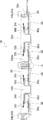
- FIG. 7 is a partial enlarged cross-sectional view showing the bus bar before caulking used in the plate assembled battery of FIG. 1, and FIG. 8 shows the bus bar after caulking used in the plate assembled battery of FIG. It is an expanded sectional view and shows the bus bar of the part C in FIG.
- the negative electrode bus bar 32 further includes a negative electrode connecting portion 32c disposed at the other end, and the positive electrode bus bar 42 further includes a positive electrode connecting portion 42c disposed at the other end, and the negative electrode connecting portion 32c.
- the positive electrode coupling portion 42c are electrically connected to each other by caulking or bolt fastening.
- the negative electrode bus bar 32 has a negative electrode connecting portion 32c at the end opposite to the negative electrode stacked connection portions 32a and 32b
- the positive electrode bus bar 42 has a positive electrode at the end opposite to the positive electrode stacked connection portions 42a and 42b.
- There is a connecting portion 42c, and the negative electrode connecting portion 32c and the positive electrode connecting portion 42c are electrically connected to each other by caulking or bolt fastening which can be connected more easily than the conventional “metallic coupling”.
- the negative electrode bus bar 34 further includes a negative electrode connecting portion 34c (not shown) disposed at the other end, and the positive electrode bus bar 44 further includes a positive electrode connecting portion 44c (not illustrated) disposed at the other end.
- the negative electrode connecting portion 34c and the positive electrode connecting portion 44c are electrically connected to each other in the same manner.
- the negative electrode bus bar 36 is the same as the negative electrode bus bars 32, 34, and the positive electrode bus bar 46 is the same as the positive electrode bus bars 42, 44, and thus the description thereof is omitted.
- caulking in this specification means not only that the rivets fitted to a plurality of parts are plastically deformed and joined, but also a part of a plurality of parts is plastically processed and joined together. To do.
- the electrical connection surfaces of the negative electrode coupling portions 32c, 34c, and 36c and the positive electrode coupling portions 42c, 44c, and 46c of the plate assembled battery 10 of the present invention are the longitudinal direction of the negative electrode bus bars 32, 34, and 36, and the positive electrode bus bar 42, They may be arranged so as to extend in the longitudinal direction of 44 and 46 and to face each other. That is, as shown in FIGS. 7 and 8, the side surface of the negative electrode connecting portion 32 c extending in the longitudinal direction of the negative electrode bus bar 32 and the side surface of the positive electrode connecting portion 42 c extending in the longitudinal direction of the positive electrode bus bar 42 are arranged to face each other. And an electrical connection surface is formed between them.
- a cylindrical member made of copper is attached to the negative electrode connecting portion 32c, and a through hole is provided in the positive electrode connecting portion 42c. After the cylindrical member and the through hole are fitted, the cylindrical member is crushed while opening the tip.
- the negative electrode coupling part 32c and the positive electrode coupling part 42c are electrically connected by plastic deformation.
- the negative electrode coupling part 32c and the positive electrode coupling part 42c may be electrically connected by bolt fastening. Since the negative electrode connecting portion 34c and the positive electrode connecting portion 44c, and the negative electrode connecting portion 36c and the positive electrode connecting portion 46c are the same, description thereof will be omitted.
- the electrical connection surfaces of the negative electrode coupling portions 32c, 34c, and 36c and the positive electrode coupling portions 42c, 44c, and 46c of the plate assembled battery 10 of the present invention are the longitudinal direction of the negative electrode bus bars 32, 34, and 36, and the positive electrode bus bar 42, They may be arranged so as to extend perpendicularly to the longitudinal direction of 44 and 46 and to face each other. That is, although not shown, the end surface of the negative electrode coupling portion 32c extending perpendicularly to the longitudinal direction of the negative electrode bus bar 32 and the end surface of the positive electrode coupling portion 42c extending perpendicularly to the longitudinal direction of the positive electrode bus bar 42 face each other. And an electrical connection surface is formed between them. Since the negative electrode connecting portion 34c and the positive electrode connecting portion 44c, and the negative electrode connecting portion 36c and the positive electrode connecting portion 46c are the same, description thereof will be omitted.
- the plate-like assembled battery of the present invention can be easily assembled equal to or higher than the conventional one and can maintain high quality.
- At least a part of the electrical connection surface between the negative electrode coupling portion 32c and the positive electrode coupling portion 42c is configured to be disposed outside any of the plurality of storage portions 52a to 52d. That is, at least a part of the electrical connection surface between the negative electrode coupling part 32 c and the positive electrode coupling part 42 c is arranged outside the storage part 52 so as not to touch the electrolyte injected into the storage part 52. .
- At least a part of the electrical connection surface between the negative electrode connecting portion 34c and the positive electrode connecting portion 44c is configured to be disposed outside any of the plurality of storage portions 52a to 52d.
- the electrical connection surface between the negative electrode coupling portion 36c (not shown) and the positive electrode coupling portion 46c (not shown) is the electrical connection surface between the negative electrode coupling portion 32c and the positive electrode coupling portion 42c, and the negative electrode coupling portion 34c. Since this is the same as the electrical connection surface of the positive electrode connecting portion 44c, description thereof is omitted.
- the assembled battery case 50 of the plate-shaped assembled battery 10 of the present invention may have connecting portion fixing walls 56ab, 56bc, 56cd.
- the connecting portion fixing walls 56ab, 56bc, 56cd are at least a part of the whole of the negative electrode connecting portions 32c, 34c, 36c and the positive electrode connecting portions 42c, 44c, 46c electrically connected to each other in the direction along the connecting surface.
- the outer circumference is seamlessly covered over the entire circumference. That is, the connecting portion fixing wall 56ab covers the entire circumference of the negative electrode connecting portion 32c and the positive electrode connecting portion 42c, which are electrically connected to each other, at least partially in the direction along the connecting surface. is there.
- the connecting portion fixing wall 56ab seamlessly covers the entire outer periphery of the negative electrode connecting portion 32c and the positive electrode connecting portion 42c over the entire circumference because of the shrinkage of the material after the battery pack case 50 is injection molded, This is because pressure is applied to the electrical connection surface with the connecting portion 42c to block inflow of moisture and electrolyte in the air to the connection surface.
- an inspection port for directly measuring the negative electrode connecting portion 32c and the positive electrode connecting portion 42c and measuring the voltage can be provided in a part of the connecting portion fixing wall 56ab in the direction along the connecting surface.
- the connecting portion fixing wall 56bc similarly covers the negative electrode connecting portion 34c and the positive electrode connecting portion 44c
- the connecting portion fixing wall 56cd similarly covers the negative electrode connecting portion 36c and the positive electrode connecting portion 46c. The description is omitted.
- the plate-like assembled battery of the present invention can be easily manufactured without using a large-scale facility and can prevent electric corrosion. As a result, it can be easily assembled and high quality can be maintained.
- the plate assembled battery 10 of the present invention may further include a sealant.
- the sealant is applied to the interface between the negative electrode bus bar 30 and the connecting portion fixing walls 56ab, 56bc, 56cd and the interface between the positive electrode bus bar 40 and the connecting portion fixing walls 56ab, 56bc, 56cd. That is, a sealant is applied to the interface between the negative electrode bus bar 32 and the connecting portion fixing wall 56ab and the interface between the positive electrode bus bar 42 and the connecting portion fixing wall 56ab.
- the purpose is to improve the adhesion of each interface. This is to block the inflow of moisture and electrolyte in the air to each interface.
- a sealing agent may be applied to the negative electrode bus bar 32 and the positive electrode bus bar 42 and then heated.
- the sealant is not particularly limited, but is preferably a thermoplastic polyester elastomer.
- the sealant is used for the interface between the negative electrode bus bar 34 and the connecting portion fixing wall 56bc, the interface between the positive electrode bus bar 44 and the connecting portion fixing wall 56bc, the interface between the negative electrode bus bar 36 and the connecting portion fixing wall 56cd, and the positive electrode bus bar 46.
- the connection portion fixing wall 56cd are applied in the same manner, and the description thereof is omitted.
- the plate-like assembled battery of the present invention can be easily manufactured without using a large-scale facility and can prevent electric corrosion. As a result, it can be easily assembled and high quality can be maintained.
- the assembled battery case 50 of the plate-like assembled battery 10 of the present invention includes a negative electrode bus bar protection part 62, 64, 66 for covering one surface of a part of the negative electrode bus bar 30, and a part of one surface of the positive electrode bus bar 40. And positive electrode bus bar protection portions 72, 74, and 76.
- the thickness of the negative electrode bus bar protection parts 62, 64, 66 and the positive electrode bus bar protection parts 72, 74, 76 is 5 mm or less.
- the thickness of the negative electrode bus bar protection part 62 for covering a part of the lower surface of the negative electrode bus bar 32 and the thickness of the positive electrode bus bar protection part 72 for covering a part of the lower surface of the positive electrode bus bar 42 are: The purpose is to enhance the heat dissipation of the negative electrode bus bar 32 during preliminary charging. Note that the negative electrode bus bar protection units 64 and 66 and the positive electrode bus bar protection units 74 and 76 are the same, and thus the description thereof is omitted.
- the assembled battery case 50 of the plate-like assembled battery 10 includes a terminal plate protection unit 68 for covering a part of one surface of the negative electrode terminal plate 38 and a terminal for covering a part of one surface of the positive electrode terminal plate 48. And a plate protection part 78. Since the thicknesses of the terminal plate protection part 68 and the terminal plate protection part 78 are the same as those of the negative electrode bus bar protection parts 62, 64, 66 and the positive electrode bus bar protection parts 72, 74, 76, the description thereof is omitted.
- the plate-like assembled battery of the present invention can maintain high quality as easily as or more than the conventional one.
- the plate-like assembled battery 10 of the present invention further includes a negative electrode terminal plate 38 and a positive electrode terminal plate 48 that are integrally formed with the assembled battery case 50 in order to extract power from the plate-like assembled battery 10.
- At least one of the negative electrode bus bar 30 or the negative electrode terminal plate 38 and the positive electrode bus bar 40 or the positive electrode terminal plate 48 disposed therein is an injection hole portion 32d, 34d, an injection hole portion 36d, 38d for injecting an electrolytic solution ( (Not shown).
- the liquid injection hole portion 32d is provided in one or both of the negative electrode bus bar 32 and the positive electrode terminal plate 48 disposed in the storage portion 52a, and the purpose thereof is that the wall surface of each storage portion 52a is made of synthetic resin or the like. This is because the liquid injection hole is easily and surely sealed by providing the liquid injection hole in a metal bus bar having a strength higher than that of the assembled battery case 50 made of an insulating material.
- a hole is provided at a position corresponding to the liquid injection hole 32d of the assembled battery case 50, and the electrolytic solution is injected from the liquid injection hole 32d exposed from the hole. In the case where there is no liquid injection hole 32d, it is necessary to inject the electrolyte before the sealing plate 80 is screwed.
- the plate-like assembled battery of the present invention can be easily assembled equal to or higher than the conventional one and can maintain high quality.
- the liquid injection holes 32d, 34d, 36d, and 38d of the plate assembled battery 10 of the present invention are fixed to the liquid injection holes 32d, 34d, 36d, and 38d by caulking to assist sealing of the liquid injection holes.
- a liquid filling auxiliary member may be included. That is, a caulking nut for assisting the sealing of the liquid injection hole is fixed to the liquid injection hole portion 32d, and the hole is sealed with a screw. This is because the plate-shaped bus bar is formed with higher strength than the direct processing.
- an O-ring integrated type may be used in order to improve the sealing performance.
- the liquid injection hole portions 34d, 36d, and 38d are the same, and thus the description thereof is omitted.
- the plate-like assembled battery of the present invention can be easily assembled equal to or higher than the conventional one and can maintain high quality.
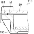
- FIG. 9 is a partially enlarged cross-sectional view showing a plate-shaped assembled battery of Modification 1 of the first embodiment of the present invention.
- the plate-like assembled battery 110 of Modification 1 is the same as the plate-like assembled battery 10 of the present invention except that the O-ring grooves 54a to 54d are not provided and the film 184 is provided instead of the O-rings 82a to 82d. Since it has a structure, description of the same component is abbreviate
- a film 184 for hermetically sealing each storage portion 52 may be mounted between the assembled battery case 150 and the sealing plate 80 of the plate-shaped assembled battery 110 of the present invention. That is, in order to hermetically seal each storage portion 52, a film 184 is mounted between the assembled battery case 150 and the sealing plate 80, and a surface having a concave portion of the assembled battery case 150 using a heat sealer or the like.
- the film 184 of the part M around each storage part 52 is thermally welded to the assembled battery case 150, and the sealing plate 80 is screw-fixed thereon, the purpose of which is more than when an O-ring is used. This is because the deflection due to the reaction force is small, so that the sealing plate 80 is made thin and the heat dissipation and assembling properties are improved.
- ultrasonic welding, adhesion or caulking may be used, and a gasket may be incorporated instead of the film 184.
- the plate-like assembled battery of the present invention can be easily assembled equal to or higher than the conventional one and can maintain high quality.
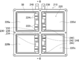
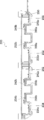
- FIG. 10 is a plan view showing a state in which the sealing plate is removed from the plate-shaped assembled battery of Modification 2 of the first embodiment of the present invention
- FIG. 11 shows the plate-shaped assembled battery of FIG. It is sectional drawing cut
- the plate-like assembled battery 210 of Modification 2 is different from the plate-like assembled battery 10 of the present invention in that the arrangement of the negative electrode current collectors 22t and the positive electrode current collectors 24t of the unit cell elements 20a to 20d is different. Since the bus bars 32, 34, and 36 and the positive electrode bus bars 42, 44, and 46 have the same configuration except that they have different shapes, description of the same components is omitted.
- the single cell element 220 includes single cell elements 220a to 220d, the negative electrode bus bar 230 includes negative electrode bus bars 232, 234, and 236, and the positive electrode bus bar 240 includes positive electrode bus bars 242, 244, and 246.
- the negative electrode bus bar 230 and the positive electrode bus bar 240 of the plate-shaped assembled battery 210 of the present invention may have a plate shape bent stepwise. That is, the shape of the negative electrode bus bar 232 is a plate bent in a staircase shape. The purpose of the negative electrode bus bar 232 is to connect the negative electrode current collector 222t of the unit cell element 220 to the lower layer negative electrode stack connection portion 232a and the upper step.
- the negative electrode current collector 222t is prevented from being broken and poorly connected, and the lower layer negative electrode stacking connection portion 232a and the upper negative electrode This is because the simultaneous assembly to the stacked connection portion 232b improves productivity as compared with the case where a bus bar bent in a U-shape is used.
- Half of the negative electrode current collectors 222t can be ultrasonically welded to the lower layer negative electrode connector 232a of the stairs, and at the same time, half of the negative electrode current collectors 222t can be ultrasonically welded to the upper electrode negative electrode layer connector 232b. . Since the negative electrode bus bars 234 and 236 and the negative electrode terminal plate 238 are the same, description thereof is omitted.
- the shape of the positive electrode bus bar 242 is also a plate shape bent in a staircase shape, and the purpose of the positive electrode bus bar 242 is also the same as that of the positive electrode stacking connection portion at the lower stage of the staircase.
- 242a and the upper positive electrode stacking connection part 242b are provided at two locations, and the number of connections per one point is halved to prevent tearing of the positive current collector 224t and poor connection, and at the lower step of the positive electrode stacking connection part 242a. This is because the simultaneous assembly into the upper positive electrode stacking connection portion 242b improves productivity more than when using a U-shaped bent bus bar.
- Half of the positive electrode current collectors 224t can be ultrasonically welded to the lower positive electrode layered connection 242a of the staircase, and half of the positive electrode current collectors 224t can be ultrasonically welded to the upper positive electrode layered connection 242b.
- the positive bus bars 244 and 246 and the positive terminal plate 248 are the same and will not be described. Ultrasonic welding of the lower layer negative electrode connection 232a and the upper negative electrode layer connection 232b and the ultrasonic welding of the lower layer positive electrode layer connection 242a and upper step positive electrode layer connection 242b are all performed simultaneously. May be.
- the plate-like assembled battery of the present invention can maintain high quality as easily as or more than the conventional one.
- FIG. 12 is a cross-sectional view of a plate-shaped assembled battery according to Modification 3 of the first embodiment of the present invention.
- the plate-like assembled battery 310 of Modification 3 is different from the plate-like assembled battery 210 of the present invention in that the upper negative electrode laminated connection portions 232b, 234b, 236b and the upper positive electrode laminated connection portions 242b, 244b of the positive electrode bus bar. Since the assembled battery case 250 has the same configuration except that the portions of the battery pack case 250 adjacent to the H.246b have different thicknesses, the description of the same components will be omitted.
- the thickness of the assembled battery case 350 at the portion adjacent to the upper negative electrode stacked connection portions 232b, 234b, 236b and the upper positive electrode stacked connection portions 242b, 244b, 246b of the negative electrode bus bar of the plate-shaped assembled battery 310 of the present invention Is approximately the same as the thickness of the assembled battery case 350 in the portion adjacent to the lower layer negative electrode stacking connections 232a, 234a, 236a and the lower layer positive electrode stacking connections 242a, 244a, 246a, respectively.
- concave portions 358a to 358d are provided from the lower side to the upper side of the assembled battery case 350.
- the purpose of the concave portions 358a to 358d is to reduce the weight of the assembled battery case and to the negative electrode laminated connection portions 232b, 234b, 236b, 238b in the upper stage.
- the negative electrode current collector 222t is ultrasonically welded, and the upper positive electrode laminate connection part 24 b, 244b, 246b, in order to prevent the attenuation of ultrasonic waves at the time of ultrasonic welding the positive electrode current collecting portion 224t to 248 b.
- the plate-like assembled battery of the present invention can maintain high quality as easily as or more than the conventional one.
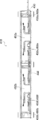
- FIG. 13 is a cross-sectional view of the plate assembled battery according to the second embodiment of the present invention.
- the plate-like assembled battery 410 according to the second embodiment is different from the plate-like assembled battery 10 of the present invention in that it has storage portions 452a to 452d that penetrate therethrough instead of the storage portions 52a to 52d that have bottoms. Except for the point having 486, the point having O-ring grooves 458a to 458h on the lower surface of the assembled battery case 450, and the point having O-rings 488a to 488h, the description of the same components is omitted. To do.
- the storage portions 452a to 452d of the plate-like assembled battery 410 according to the second embodiment of the present invention may be through holes.
- the sealing plates 80 and 486 may be screwed to a pair of opposed surfaces having through holes of the assembled battery case 450. That is, the storage portions 452a to 452d are through holes in which the bottom surface of the storage portion 52 of the plate-like battery pack 10 according to the first embodiment of the present invention is removed.
- O-ring grooves 458a to 458d are formed around the storage portions 452a to 452d on the lower surface of the assembled battery case 450, and O-rings 488a to 488d are formed therein.
- the O-ring groove 458e is formed around the holes provided at the positions corresponding to the liquid injection holes 32d, 34d, 36d, and 38d on the lower surface.
- the material and shape of the sealing plate 486 may be the same as that of the sealing plate 80. Further, when there is no liquid injection hole portion 32d, 34d, 36d, 38d, it is necessary to inject the electrolytic solution after screwing one of the sealing plates 80, 486 and before screwing the other. Further, instead of screwing the sealing plates 80 and 486 to the assembled battery case 450, ultrasonic welding or adhesion or caulking may be used, or the film or gasket of the first modification may be used instead of the O-ring. good.
- the plate assembled battery of the present invention is basically configured as described above.
- the plate-like assembled battery of the present invention can be easily manufactured without using a large-scale facility and can prevent electric corrosion, it can be easily assembled to be equal to or more than conventional. Can be maintained and high quality can be maintained, which is industrially useful.
Landscapes
- Chemical & Material Sciences (AREA)
- Chemical Kinetics & Catalysis (AREA)
- Electrochemistry (AREA)
- General Chemical & Material Sciences (AREA)
- Inorganic Chemistry (AREA)
- Connection Of Batteries Or Terminals (AREA)
Abstract
L'invention concerne une batterie assemblée en forme de plaque de telle sorte que la batterie peut être facilement produite sans utiliser d'équipement à grande échelle et de telle sorte qu'une corrosion galvanique est empêchée. La batterie assemblée en forme de plaque (10) comprend une pluralité de mono-éléments de batterie (20), une barre omnibus d'électrode négative allongée (30), une barre omnibus d'électrode positive allongée (40), un boîtier de batterie assemblée en forme de plaque plate (50) et une plaque d'étanchéité (80). La barre omnibus d'électrode négative allongée (30) qui comprend un matériau conducteur et la barre omnibus d'électrode positive allongée (40) qui comprend un matériau conducteur différent de celui de la barre omnibus d'électrode négative (30) sont conçues de façon à être intégrées au boîtier de batterie assemblée (50) dans un état de communication l'une avec l'autre. Le boîtier de batterie assemblée en forme de plaque plate comporte un matériau isolant et contient chacun des éléments de la pluralité de mono-éléments de batterie (20) dans chacune des parties de boîtier (52). Au moins une partie de chaque mono-élément de batterie de la pluralité de mono-éléments de batterie (20) est dans un état découvert à l'intérieur des parties de boîtier respectives (52). Une partie d'extrémité d'une barre omnibus d'électrode négative (32) et une partie d'extrémité d'une barre omnibus d'électrode positive (42) sont connectées électriquement l'une à l'autre par sertissage ou fixation par boulon, et au moins une partie de cette surface de connexion électrique est conçue de manière à être disposée à l'extérieur de l'une quelconque de la pluralité des parties de boîtier (52).
Priority Applications (1)
| Application Number | Priority Date | Filing Date | Title |
|---|---|---|---|
| PCT/JP2016/061447 WO2017175362A1 (fr) | 2016-04-07 | 2016-04-07 | Batterie assemblée en forme de plaque |
Applications Claiming Priority (1)
| Application Number | Priority Date | Filing Date | Title |
|---|---|---|---|
| PCT/JP2016/061447 WO2017175362A1 (fr) | 2016-04-07 | 2016-04-07 | Batterie assemblée en forme de plaque |
Publications (1)
| Publication Number | Publication Date |
|---|---|
| WO2017175362A1 true WO2017175362A1 (fr) | 2017-10-12 |
Family
ID=60001095
Family Applications (1)
| Application Number | Title | Priority Date | Filing Date |
|---|---|---|---|
| PCT/JP2016/061447 Ceased WO2017175362A1 (fr) | 2016-04-07 | 2016-04-07 | Batterie assemblée en forme de plaque |
Country Status (1)
| Country | Link |
|---|---|
| WO (1) | WO2017175362A1 (fr) |
Cited By (2)
| Publication number | Priority date | Publication date | Assignee | Title |
|---|---|---|---|---|
| CN108461802A (zh) * | 2018-04-09 | 2018-08-28 | 江西恒动新能源有限公司 | 一种储能模块电芯的摆置结构及摆置方法 |
| JP2023550165A (ja) * | 2021-08-23 | 2023-11-30 | 寧徳時代新能源科技股▲分▼有限公司 | 電池セル、電池及び電力消費装置 |
Citations (4)
| Publication number | Priority date | Publication date | Assignee | Title |
|---|---|---|---|---|
| JP2005116457A (ja) * | 2003-10-10 | 2005-04-28 | Nissan Motor Co Ltd | 組電池とその製造方法 |
| JP2006128009A (ja) * | 2004-10-29 | 2006-05-18 | Toyota Motor Corp | 蓄電モジュールと該モジュール用枠体 |
| WO2010087472A1 (fr) * | 2009-02-02 | 2010-08-05 | 株式会社Gsユアサ | Conducteur de connexion de bornes, batterie assemblée et procédé de fabrication d'une batterie assemblée |
| JP2015005488A (ja) * | 2013-05-23 | 2015-01-08 | Connexx Systems株式会社 | 板状組電池およびこれらを複数個組み合わせて構成される板状組電池群 |
-
2016
- 2016-04-07 WO PCT/JP2016/061447 patent/WO2017175362A1/fr not_active Ceased
Patent Citations (4)
| Publication number | Priority date | Publication date | Assignee | Title |
|---|---|---|---|---|
| JP2005116457A (ja) * | 2003-10-10 | 2005-04-28 | Nissan Motor Co Ltd | 組電池とその製造方法 |
| JP2006128009A (ja) * | 2004-10-29 | 2006-05-18 | Toyota Motor Corp | 蓄電モジュールと該モジュール用枠体 |
| WO2010087472A1 (fr) * | 2009-02-02 | 2010-08-05 | 株式会社Gsユアサ | Conducteur de connexion de bornes, batterie assemblée et procédé de fabrication d'une batterie assemblée |
| JP2015005488A (ja) * | 2013-05-23 | 2015-01-08 | Connexx Systems株式会社 | 板状組電池およびこれらを複数個組み合わせて構成される板状組電池群 |
Cited By (4)
| Publication number | Priority date | Publication date | Assignee | Title |
|---|---|---|---|---|
| CN108461802A (zh) * | 2018-04-09 | 2018-08-28 | 江西恒动新能源有限公司 | 一种储能模块电芯的摆置结构及摆置方法 |
| JP2023550165A (ja) * | 2021-08-23 | 2023-11-30 | 寧徳時代新能源科技股▲分▼有限公司 | 電池セル、電池及び電力消費装置 |
| JP7689574B2 (ja) | 2021-08-23 | 2025-06-06 | 香港時代新能源科技有限公司 | 電池セル、電池及び電力消費装置 |
| US12597682B2 (en) | 2021-08-23 | 2026-04-07 | Contemporary Amperex Technology (Hong Kong) Limited | Battery cell, battery, and electric apparatus |
Similar Documents
| Publication | Publication Date | Title |
|---|---|---|
| JP6315269B2 (ja) | 密閉型電池モジュール及びその製造方法 | |
| CN103180996B (zh) | 带电极端子的电池盖、带电极端子的电池盖的制造方法以及密闭型电池 | |
| JP5558569B2 (ja) | 電池及び組電池 | |
| CN106575721B (zh) | 方形二次电池 | |
| JP6363893B2 (ja) | 二次電池 | |
| US20170125778A1 (en) | Rectangular Secondary Battery | |
| US9698408B2 (en) | Secondary battery | |
| KR101675623B1 (ko) | 이차 전지 및 그 제조 방법 | |
| US20190319301A1 (en) | Nonaqueous electrolyte secondary battery and method of manufacturing the same | |
| US10158107B2 (en) | Battery comprising insulative films | |
| KR20190060779A (ko) | 배터리 | |
| EP3509126B1 (fr) | Batterie secondaire prismatique | |
| US7754379B2 (en) | Secondary battery | |
| JP5679271B2 (ja) | 電極端子付き電池蓋、電極端子付き電池蓋の製造方法および密閉型電池 | |
| WO2017175362A1 (fr) | Batterie assemblée en forme de plaque | |
| JP5470603B2 (ja) | 密閉型電池 | |
| JP2022014715A (ja) | 二次電池 | |
| US20130266850A1 (en) | Electrochemical cell and method for manufacturing same | |
| JP2020149935A (ja) | 電池モジュール | |
| KR20170006046A (ko) | 파우치형 이차전지 | |
| JP2022026712A (ja) | 蓄電セル及び蓄電装置 |
Legal Events
| Date | Code | Title | Description |
|---|---|---|---|
| NENP | Non-entry into the national phase |
Ref country code: DE |
|
| 121 | Ep: the epo has been informed by wipo that ep was designated in this application |
Ref document number: 16897919 Country of ref document: EP Kind code of ref document: A1 |
|
| 122 | Ep: pct application non-entry in european phase |
Ref document number: 16897919 Country of ref document: EP Kind code of ref document: A1 |
|
| NENP | Non-entry into the national phase |
Ref country code: JP |