WO2017175374A1 - Dispositif d'acquisition d'image - Google Patents
Dispositif d'acquisition d'image Download PDFInfo
- Publication number
- WO2017175374A1 WO2017175374A1 PCT/JP2016/061531 JP2016061531W WO2017175374A1 WO 2017175374 A1 WO2017175374 A1 WO 2017175374A1 JP 2016061531 W JP2016061531 W JP 2016061531W WO 2017175374 A1 WO2017175374 A1 WO 2017175374A1
- Authority
- WO
- WIPO (PCT)
- Prior art keywords
- light
- signal
- illumination light
- intensity
- illumination
- Prior art date
- Legal status (The legal status is an assumption and is not a legal conclusion. Google has not performed a legal analysis and makes no representation as to the accuracy of the status listed.)
- Ceased
Links
Images


Classifications
-
- G—PHYSICS
- G01—MEASURING; TESTING
- G01N—INVESTIGATING OR ANALYSING MATERIALS BY DETERMINING THEIR CHEMICAL OR PHYSICAL PROPERTIES
- G01N21/00—Investigating or analysing materials by the use of optical means, i.e. using sub-millimetre waves, infrared, visible or ultraviolet light
- G01N21/62—Systems in which the material investigated is excited whereby it emits light or causes a change in wavelength of the incident light
- G01N21/63—Systems in which the material investigated is excited whereby it emits light or causes a change in wavelength of the incident light optically excited
- G01N21/64—Fluorescence; Phosphorescence
-
- G—PHYSICS
- G02—OPTICS
- G02B—OPTICAL ELEMENTS, SYSTEMS OR APPARATUS
- G02B21/00—Microscopes
-
- G—PHYSICS
- G02—OPTICS
- G02B—OPTICAL ELEMENTS, SYSTEMS OR APPARATUS
- G02B21/00—Microscopes
- G02B21/06—Means for illuminating specimens
Definitions
- the present invention relates to an image acquisition device.
- the present invention has been made in view of the above-described circumstances, and an operator can accurately acquire a signal light image regardless of environmental changes without adjusting the intensity ratio of illumination light for each observation.
- An object of the present invention is to provide an image acquisition device capable of performing the above.
- a modulation unit that generates illumination light in which two different states are periodically switched by modulating light from a light source, and illumination that detects the illumination light generated by the modulation unit
- a light detection unit an illumination optical system that irradiates the sample with the illumination light generated by the modulation unit; and the signal light generated at the illumination light irradiation position on the sample by the illumination optical system is collected and detected.
- illumination light in which two different states are switched periodically is generated, and the generated illumination light is irradiated onto the sample by the illumination optical system. Is done.
- the signal light generated at the irradiation position of the illumination light on the sample is detected by the signal light detector.
- the intensity signal of the detected signal light is demodulated by the demodulator, and a signal light image is generated by the image generator based on the demodulated signal light intensity signal.
- the illumination light generated by the modulation unit is detected by the illumination light detection unit, and the intensity signal of the detected illumination light is demodulated by the demodulation unit.
- the intensity signal in each state of illumination light having two states can be compared by the modulation unit, and the intensity signal of the illumination light in two states can be obtained even when the modulation ratio by the modulation unit varies due to environmental changes. Correction can be performed in the modulation section so that the ratio is constant.
- the signal light image can be accurately acquired regardless of the environmental change without the operator adjusting the intensity ratio of the illumination light for each observation.
- the two states are states in which time integrated intensity is equal
- the demodulator outputs a difference in time integrated intensity of the illumination light demodulated for each state
- the modulator is The modulation intensity may be corrected so that the difference becomes zero.
- the modulation intensity is corrected by the modulation unit until the difference in time integration intensity of the illumination light output from the demodulation unit becomes zero, thereby making the time integration intensity of the illumination light in the two states equal. Can be maintained.
- the state where the time integrated intensities of the two states are equal includes not only the case where the intensity of the illumination light is equal but also the case where the intensities are different.
- the state which irradiates the said illumination light to the different position of a sample may be sufficient as said two states.
- it is applied to a scanning confocal microscope, and the illumination light in one state is condensed at a position optically conjugate with the pinhole in front of the detector, and the illumination light in the other state is condensed.
- the light is condensed at a position optically unconjugated with the pinhole.
- the focus signal light from the condensing position and the out-of-focus signal light from other than the condensing position pass through the pinhole, and in the other state, only the out-of-focus signal light passes through the pinhole.
- the out-of-focus fluorescence can be accurately removed by correcting the intensity of the illumination light applied to the sample in the two states in the modulation unit so as to match with high accuracy.
- the two states may be a state where the signal light generated in the sample is saturated and a state where the signal light is not saturated.
- SAX saturated Excitation
- the time integrated intensity of the illumination light is the same in the two states, but the signal light generated in the sample is saturated with the illumination light with the higher intensity.
- high-precision observation can be performed by accurately matching the time integrated intensities of the illumination light in the two states.
- the optical system includes a branching unit that branches the light from the light source into two optical paths, and the modulation unit modulates the light of each optical path branched by the branching unit with a different frequency, respectively.
- the modulation intensity of the illumination light may be corrected so that the intensity ratio of the two illumination lights demodulated by the demodulator has a preset value.
- the obtained signal light intensity is proportional to the square of the instantaneous intensity of the illumination light. Even if the intensities are matched, there is a difference in the intensity of the detected signal light. According to this aspect, it is possible to acquire a signal light image without color unevenness by correcting the modulation intensity of the illumination light so as to obtain a preset intensity ratio in consideration of the irradiation pattern.
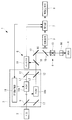
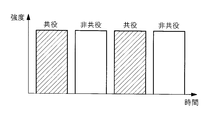
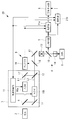
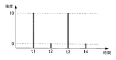
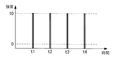
- FIG. 1 is an overall configuration diagram illustrating an image acquisition device according to a first embodiment of the present invention. It is a figure which shows an example of the illumination light modulated by the modulation part of the image acquisition apparatus of FIG. It is a figure which shows an example of the illumination light used for the modification of the image acquisition apparatus of FIG. It is a whole block diagram which shows the image acquisition apparatus which concerns on the 2nd Embodiment of this invention. It is a figure which shows an example of the illumination light modulated by the 1st modulator of the image acquisition apparatus of FIG. It is a figure which shows an example of the laser beam inject
- the image acquisition apparatus 1 includes a laser light source (light source) 2 that emits laser light having a constant intensity, and a modulation unit that modulates laser light from the laser light source 2.
- a laser light source (light source) 2 that emits laser light having a constant intensity
- a modulation unit that modulates laser light from the laser light source 2.
- a microscope optical system for condensing fluorescence (signal light) generated in the sample X while irradiating the illumination light modulated in the modulation unit 3 to the sample X (not shown), and the microscope
- a photodetector (signal light detection unit) 5 for detecting fluorescence that has passed through the pinhole 16 of the optical system 4
- a detector (illumination light detection unit) 6 for detecting the illumination lights L1 and L2 modulated by the modulation unit 3; Based on the fluorescence intensity signal detected by the photodetector 5 and the intensity signal of the illumination lights L1 and L2 detected by the detector 6, the demodulator 7 and the fluorescence intensity signal demodulated by the demodulator 7 To generate fluorescent images And an image generation unit 8 that.
- the modulation unit 3 is arranged on each optical path and a first beam splitter (branching unit) 9 that branches the laser light from the laser light source 2 into two optical paths, and turns on and off the laser light that passes through each optical path at alternate timings.
- Modulators 10a and 10b such as an acousto-optic modulator (AOM) that modulates in this way, a modulation control unit 11 that controls these modulators 10a and 10b, and illumination light L1 output from the modulators 10a and 10b
- AOM acousto-optic modulator
- the second beam splitter 12 is arranged at an angle slightly different from 45 ° with respect to the optical axis of one optical path, and the two illumination lights L1 and L2 after being combined are emitted at different angles. It is like that.
- the microscope optical system 4 is an optical system of a laser scanning fluorescence microscope, and includes a scanner 13 that scans two illumination lights L1 and L2 emitted from the modulation unit 3, and an illumination light L1 that is scanned by the scanner 13. , L2 on the sample X, a dichroic mirror 15 for branching the fluorescence condensed by the objective lens 14 from the optical path of the illumination light L1, L2, and a pinhole 16.
- reference numeral 17 denotes an optical path forming mirror.
- the two illumination lights L1 and L2 having different emission angles by the second beam splitter 12 of the modulation unit 3 are incident on the pupil of the objective lens 14 from different angles, thereby being condensed at different positions in the sample X.
- the fluorescent material existing in the sample X is excited to generate fluorescence. That is, the illumination light L1 that has passed through one optical path is condensed at a position optically conjugate with the pinhole 16 disposed in the front stage of the photodetector 5, while the illumination light L2 that has passed through the other optical path. Is condensed at a position optically unconjugated with the pinhole 16.
- the illumination light L1 and L2 passing through the two optical paths are alternately emitted by the operation of the modulation control unit 11, as shown in FIG. 2, the illumination light L1 that is condensed at the conjugate position and the non-conjugated light Illumination light is generated in which the illumination light L1, L2 in two states of the illumination light L2 condensed at the position is switched periodically.
- the modulation control unit 11 outputs a modulation signal to the demodulation unit 7.
- the photodetector 5 is, for example, a photomultiplier tube, and detects the intensity of the fluorescence condensed by the objective lens 14.
- the demodulating unit 7 modulates the intensity signals of the fluorescence generated by the illumination lights L1 and L2 in the two states detected by the photodetector 5 by the modulators 10a and 10b sent from the modulation control unit 11, respectively.
- the signal is demodulated in synchronization with the timing, and the difference between the fluorescence intensity signals is output.
- the image generator 8 generates a fluorescent image by arranging the difference value of the fluorescence intensity signal output from the demodulator 7 in association with the information of the scanning position by the scanner 13.
- the fluorescence detected by the photodetector 5 includes the focus fluorescence generated at the focus position and the path to the focus in the sample X. Part of the generated out-of-focus fluorescence is included.
- the fluorescence detected by the photodetector 5 when the illumination light L2 is condensed at a position unconjugated with the pinhole 16 includes the focus fluorescence generated at the focal position because it cannot pass through the pinhole 16. Only the out-of-focus fluorescence is included. Therefore, the difference between these fluorescence intensity signals output from the demodulator 7 includes only the focus fluorescence from which the out-of-focus fluorescence is removed, and a clear fluorescence image with less noise is generated. Will be able to.
- the detector 6 is disposed, for example, at the subsequent stage of the modulation unit 3, and includes a beam sampler 18 including a low-reflectance half mirror that separates part of the illumination lights L 1 and L 2 output from the modulation unit 3, and the beam sampler 18. And a single point detector 19 disposed at a position where the illumination lights L1 and L2 in the two states separated by (2) can be detected.
- the single point detector 19 may be arranged at a position conjugate with the pupil plane of the objective lens 14 by a relay lens (not shown), may be arranged at the focal position of a condenser lens (not shown), or two illuminations You may employ
- the output of the single point detector 19 is input to the demodulator 7, and the output from the demodulator 7 is input to the modulation controller 11.
- the modulation control unit 11 corrects the modulation intensity of the illumination lights L1 and L2 modulated by one of the modulators 10a and 10b in accordance with the difference value input from the demodulation unit 7. That is, based on the intensity of the illumination lights L1 and L2 in two states separated by the beam sampler 18, the modulation control unit 11 sets the intensity of any illumination light so that the output from the demodulation unit 7 becomes zero. Therefore, the intensities of the illumination lights L1 and L2 in the two states are adjusted with high accuracy.
- the laser light emitted from the laser light source 2 is branched into two optical paths by the first beam splitter 9 in the modulation unit 3 and passes through the optical paths. During this time, the light is modulated by the modulators 10a and 10b arranged in the respective optical paths, combined by the second beam splitter 12, and emitted at different angles.
- Illumination lights L1 and L2 output from the modulation unit 3 and that change in two states in terms of time are made incident on the microscope optical system 4, and a part of the illumination lights L1 and L2 are separated by the beam sampler 18 and single point detector 19 is used. Is detected.
- the illumination lights L1 and L2 in two states scanned by the scanner 13 in the microscope optical system 4 and condensed by the objective lens 14 are condensed at two different positions in the sample X, and fluorescent at each condensing position. Is generated.
- Fluorescence generated in the sample X by irradiation with the illumination lights L1 and L2 in two states is detected by the photodetector 5 and input to the demodulator 7.
- the difference between the fluorescence intensity signals generated by the illumination lights L 1 and L 2 in each state is output from the demodulator 7.
- the difference in the intensity signal of the fluorescence output from the demodulator 7 is an intensity signal of only the fluorescence from the focal position of the illumination light from which the out-of-focus fluorescence is removed.
- the intensities of the illumination lights L1 and L2 in the two states are required to be the same.
- the modulation control unit 11 is set so that the intensity of the illumination lights L1 and L2 in the two states output from the modulation unit 3 are the same, but the use environment such as temperature fluctuates, There may be a difference in the intensity of the illumination lights L1 and L2 output from the modulators 10a and 10b.
- part of the illumination lights L1 and L2 output from the modulation unit 3 are separated by the beam sampler 18, detected by the single point detector 19, and detected illumination light L1.
- L2 intensity signals are demodulated by the demodulator 7 so that the difference between the signal intensities of the two illumination lights L1 and L2 is output from the demodulator 7.
- the difference output from the demodulator 7 is input to the modulation control unit 11, so that the modulation intensity of the illumination lights L1 and L2 modulated by the modulators 10a and 10b according to the difference is modulated by the modulation control unit 11. It is corrected.
- the demodulator 7 that outputs the difference between the fluorescence intensity signals is used to obtain the difference between the intensity signals of the illumination lights L1 and L2, so that the beam sampler 18 and the single point detector 19
- a demodulator for illumination light may be prepared separately from the demodulator 7 for fluorescence.
- the image acquisition device 1 that uses modulation / demodulation to remove out-of-focus fluorescence has been described as an example, but instead, this is applied to a SAX microscope as shown in FIG. You may decide. That is, as shown in FIG. 3, the modulation unit 3 generates illumination lights L1 and L2 having two different peak values and equal time integration intensities, unlike the above embodiment. Yes.
- the modulators 10a and 10b may employ electro-optic modulators instead of the acousto-optic modulators.
- the illumination light L1 having a higher peak intensity saturates the fluorescence generated in the sample X and the illumination light L2 having a lower peak intensity does not saturate the fluorescence, even if the usage environment changes, two In this state, the time integrated intensities of the illumination lights L1 and L2 can be maintained in a highly accurate state, and high-precision observation can be performed.
- an image acquisition apparatus 20 according to a second embodiment of the present invention will be described below with reference to the drawings.
- the same reference numerals are given to portions having the same configuration as that of the image acquisition device 1 according to the first embodiment described above, and description thereof is omitted.
- the image acquisition device 20 is applied to a two-photon excitation microscope, and divides illumination light composed of ultrashort pulse laser light into two optical paths, The light is modulated at different frequencies by the arranged modulators 10a and 10b, condensed at two different points of the sample X, and the fluorescence emitted from each focal point is detected and demodulated to detect the fluorescence from the two points.
- the light is modulated at different frequencies by the arranged modulators 10a and 10b, condensed at two different points of the sample X, and the fluorescence emitted from each focal point is detected and demodulated to detect the fluorescence from the two points.
- the first modulator 10a in one optical path cuts every other pulse of the ultrashort pulse laser light from the laser light source 2 to become 50% duty. So that it can be modulated.
- the other second modulator 10b reduces the peak intensity of all pulses of the ultrashort pulse laser beam from the laser light source 2 shown in FIG. 5B to 70% as shown in FIG. 5C. Yes.
- the first modulator 10a modulates the ultrashort pulse laser light from the laser light source 2 to generate the 40 MHz illumination light L2. Yes.
- the illumination light L2 has an alternating current pattern whose intensity changes at 40 MHz.
- the second modulator 10b modulates the peak intensity of the ultrashort pulse laser light from the laser light source 2 to 70% to generate 80 MHz illumination light L1.
- the signals are subtracted and a fluorescent signal corresponding to L2 is output.
- the fluorescence intensity signals output from the two demodulation units 21a and 21b are substantially equal, and the occurrence of uneven brightness in the fluorescence image generated using these fluorescence intensities can be prevented.
- the intensity signals of the illumination lights L1 and L2 in the two states detected by the single point detector 19 and demodulated by the demodulation units 21a and 21b are output as a difference, unlike the first embodiment. And output as separate intensity signals.
- the modulation intensity in each of the modulators 10a and 10b controls so that correction is not performed. That is, the modulation control unit 11 multiplies the intensity signal of the illumination light L1 output from the first demodulation unit 21a by a preset ratio, 10/7 in the above example, and the second value.
- the two modulators 10a and 10b are controlled so that the difference from the intensity signal of the illumination light L2 output from the demodulator 21b becomes zero.
- the image acquisition device 20 even if the usage environment changes, two-point simultaneous detection is performed without the operator adjusting the intensity ratio of the illumination lights L1 and L2 for each observation. There is an advantage that a fluorescent image with little luminance unevenness can be acquired while improving the frame rate by the above.
- the present invention is applied to a light sheet microscope for photographing fluorescence generated by sheet-like illumination light incident on different positions along the optical axis of the objective lens 14 with a camera. May be.
- the sampling ratio by the beam sampler 18 may be different for each of the illumination lights L1 and L2. Can do. In such a case, even if the two illumination lights L1 and L2 have the same intensity, they are detected as having different intensities in the single point detector 19, so that the single point detector is detected by the correction coefficient obtained in advance.
- a signal correction unit (not shown) that corrects the intensity signals of the illumination lights L1 and L2 detected by the projector 19 may be provided.
- the modulation control unit 11 corrects the modulation intensity by the two modulators 10a and 10b, the modulation intensity may be corrected by only one modulator 10a.
- the timing of correcting the modulation intensity of the illumination lights L1 and L2 is not particularly limited. For example, it is automatically performed before the fluorescence observation of the sample X is performed. do it.
- the intensity correction of the illumination lights L1 and L2 can be performed without using the sample X, and can be performed without damaging the sample X.
Landscapes
- Physics & Mathematics (AREA)
- Chemical & Material Sciences (AREA)
- Analytical Chemistry (AREA)
- General Physics & Mathematics (AREA)
- Optics & Photonics (AREA)
- Health & Medical Sciences (AREA)
- Nuclear Medicine, Radiotherapy & Molecular Imaging (AREA)
- Life Sciences & Earth Sciences (AREA)
- Biochemistry (AREA)
- General Health & Medical Sciences (AREA)
- Immunology (AREA)
- Pathology (AREA)
- Microscoopes, Condenser (AREA)
Abstract
Dans le but d'acquérir précisément une image de lumière de signal indépendamment de la variation environnementale sans qu'un opérateur ajuste le rapport d'intensité de lumière d'éclairage à chaque observation, un dispositif d'acquisition d'image (1) selon la présente invention, est pourvu de : une unité de modulation (3) pour moduler la lumière provenant d'une source de lumière (2), de façon à générer une lumière d'éclairage qui bascule entre deux états différents au cours d'un cycle temporel ; une unité de détection de lumière d'éclairage (6) pour détecter la lumière d'éclairage générée (L1, L2) ; un système optique d'éclairage (4) pour irradier un échantillon (X) avec la lumière d'éclairage générée (L1, L2) ; une unité de détection de lumière de signal (5) pour focaliser et détecter la lumière de signal au moyen de la lumière d'éclairage (L1, L2) générée à la position d'éclairage de l'échantillon (X) ; une unité de démodulation (7) pour démoduler la modulation du signal d'intensité détecté de la lumière de signal et du signal d'intensité détecté de la lumière d'éclairage ; et une unité de génération d'image (8) pour générer une image de lumière de signal sur la base du signal d'intensité démodulé de la lumière de signal, l'unité de modulation (3) corrigeant l'intensité de modulation de la lumière d'éclairage sur la base du signal d'intensité de la lumière d'éclairage démodulé par l'unité de démodulation (8).
Priority Applications (1)
| Application Number | Priority Date | Filing Date | Title |
|---|---|---|---|
| PCT/JP2016/061531 WO2017175374A1 (fr) | 2016-04-08 | 2016-04-08 | Dispositif d'acquisition d'image |
Applications Claiming Priority (1)
| Application Number | Priority Date | Filing Date | Title |
|---|---|---|---|
| PCT/JP2016/061531 WO2017175374A1 (fr) | 2016-04-08 | 2016-04-08 | Dispositif d'acquisition d'image |
Publications (1)
| Publication Number | Publication Date |
|---|---|
| WO2017175374A1 true WO2017175374A1 (fr) | 2017-10-12 |
Family
ID=60000918
Family Applications (1)
| Application Number | Title | Priority Date | Filing Date |
|---|---|---|---|
| PCT/JP2016/061531 Ceased WO2017175374A1 (fr) | 2016-04-08 | 2016-04-08 | Dispositif d'acquisition d'image |
Country Status (1)
| Country | Link |
|---|---|
| WO (1) | WO2017175374A1 (fr) |
Cited By (3)
| Publication number | Priority date | Publication date | Assignee | Title |
|---|---|---|---|---|
| CN112507956A (zh) * | 2020-12-21 | 2021-03-16 | 北京百度网讯科技有限公司 | 信号灯识别方法、装置、电子设备、路侧设备和云控平台 |
| JP2022522168A (ja) * | 2019-03-25 | 2022-04-14 | エイアイ・バイオメッド・コーポレーション | 組織検出システムおよびその使用方法 |
| US12268470B2 (en) | 2019-02-26 | 2025-04-08 | Ai Biomed Corp. | Tissue detection system and methods for use thereof |
Citations (4)
| Publication number | Priority date | Publication date | Assignee | Title |
|---|---|---|---|---|
| JP2008012852A (ja) * | 2006-07-07 | 2008-01-24 | Konica Minolta Business Technologies Inc | 画像形成装置 |
| JP2011141427A (ja) * | 2010-01-07 | 2011-07-21 | Seiko Epson Corp | プロジェクター |
| JP2015168184A (ja) * | 2014-03-07 | 2015-09-28 | 株式会社リコー | 光書き込み装置、画像形成装置及び光書き込み方法 |
| WO2015163261A1 (fr) * | 2014-04-24 | 2015-10-29 | オリンパス株式会社 | Microscope et procédé d'observation microscopique |
-
2016
- 2016-04-08 WO PCT/JP2016/061531 patent/WO2017175374A1/fr not_active Ceased
Patent Citations (4)
| Publication number | Priority date | Publication date | Assignee | Title |
|---|---|---|---|---|
| JP2008012852A (ja) * | 2006-07-07 | 2008-01-24 | Konica Minolta Business Technologies Inc | 画像形成装置 |
| JP2011141427A (ja) * | 2010-01-07 | 2011-07-21 | Seiko Epson Corp | プロジェクター |
| JP2015168184A (ja) * | 2014-03-07 | 2015-09-28 | 株式会社リコー | 光書き込み装置、画像形成装置及び光書き込み方法 |
| WO2015163261A1 (fr) * | 2014-04-24 | 2015-10-29 | オリンパス株式会社 | Microscope et procédé d'observation microscopique |
Cited By (4)
| Publication number | Priority date | Publication date | Assignee | Title |
|---|---|---|---|---|
| US12268470B2 (en) | 2019-02-26 | 2025-04-08 | Ai Biomed Corp. | Tissue detection system and methods for use thereof |
| JP2022522168A (ja) * | 2019-03-25 | 2022-04-14 | エイアイ・バイオメッド・コーポレーション | 組織検出システムおよびその使用方法 |
| JP7536028B2 (ja) | 2019-03-25 | 2024-08-19 | エイアイ・バイオメッド・コーポレーション | 組織検出システムおよびその使用方法 |
| CN112507956A (zh) * | 2020-12-21 | 2021-03-16 | 北京百度网讯科技有限公司 | 信号灯识别方法、装置、电子设备、路侧设备和云控平台 |
Similar Documents
| Publication | Publication Date | Title |
|---|---|---|
| US9158100B2 (en) | Laser microscope using phase-modulation type spatial light modulator | |
| US9606341B2 (en) | Optical apparatus | |
| US11131630B2 (en) | Method of aligning a laser-scanning fluorescence microscope and laser-scanning fluorescence microscope having an automatic aligning system | |
| US9356413B2 (en) | Laser source apparatus and laser microscope | |
| US11487093B2 (en) | Method for scanning microscopy and scanning microscope | |
| WO2019069509A1 (fr) | Dispositif de microscope à fluorescence et système de microscope à fluorescence | |
| US7915575B2 (en) | Laser scanning microscope having an IR partial transmission filter for realizing oblique illumination | |
| JP6720165B2 (ja) | 画像取得装置および画像取得方法 | |
| JP5307418B2 (ja) | 走査型レーザ顕微鏡 | |
| JP2015517681A (ja) | 試料中の関心組織を高空間分解能で画像化するための顕微鏡 | |
| WO2017175374A1 (fr) | Dispositif d'acquisition d'image | |
| JP2009145826A (ja) | 走査型顕微鏡装置 | |
| US10942345B2 (en) | Image acquisition method and image acquisition device | |
| JP5058624B2 (ja) | レーザ顕微鏡 | |
| US10261299B2 (en) | Image-acquisition apparatus and image-acquisition method | |
| JP5191352B2 (ja) | レーザ走査型顕微鏡 | |
| KR102599457B1 (ko) | 구조조명을 생성하는 현미경 장치 및 이의 동작 방법 | |
| US20140111633A1 (en) | Wide field microscope and method for wide field microscopy | |
| JPH11237554A (ja) | 走査型光学顕微鏡 | |
| JP2012150331A (ja) | 共焦点顕微鏡 | |
| WO2018084268A1 (fr) | Dispositif d'observation de fluorescence | |
| US20240302637A1 (en) | Light microscopy method and light microscopy device | |
| JP2006189468A (ja) | 1光子励起型蛍光観察装置および方法 | |
| JP2004133011A (ja) | オートフォーカス装置 | |
| JP2004109327A (ja) | オートフォーカス検出装置 |
Legal Events
| Date | Code | Title | Description |
|---|---|---|---|
| NENP | Non-entry into the national phase |
Ref country code: DE |
|
| 121 | Ep: the epo has been informed by wipo that ep was designated in this application |
Ref document number: 16897930 Country of ref document: EP Kind code of ref document: A1 |
|
| 122 | Ep: pct application non-entry in european phase |
Ref document number: 16897930 Country of ref document: EP Kind code of ref document: A1 |
|
| NENP | Non-entry into the national phase |
Ref country code: JP |