WO2017175461A1 - Machine électrique tournante à entrefer axial - Google Patents
Machine électrique tournante à entrefer axial Download PDFInfo
- Publication number
- WO2017175461A1 WO2017175461A1 PCT/JP2017/003507 JP2017003507W WO2017175461A1 WO 2017175461 A1 WO2017175461 A1 WO 2017175461A1 JP 2017003507 W JP2017003507 W JP 2017003507W WO 2017175461 A1 WO2017175461 A1 WO 2017175461A1
- Authority
- WO
- WIPO (PCT)
- Prior art keywords
- magnet
- axial gap
- gap type
- rotating electrical
- type rotating
- Prior art date
- Legal status (The legal status is an assumption and is not a legal conclusion. Google has not performed a legal analysis and makes no representation as to the accuracy of the status listed.)
- Ceased
Links
Images


Classifications
-
- H—ELECTRICITY
- H02—GENERATION; CONVERSION OR DISTRIBUTION OF ELECTRIC POWER
- H02K—DYNAMO-ELECTRIC MACHINES
- H02K1/00—Details of the magnetic circuit
- H02K1/06—Details of the magnetic circuit characterised by the shape, form or construction
- H02K1/22—Rotating parts of the magnetic circuit
-
- H—ELECTRICITY
- H02—GENERATION; CONVERSION OR DISTRIBUTION OF ELECTRIC POWER
- H02K—DYNAMO-ELECTRIC MACHINES
- H02K1/00—Details of the magnetic circuit
- H02K1/06—Details of the magnetic circuit characterised by the shape, form or construction
- H02K1/22—Rotating parts of the magnetic circuit
- H02K1/27—Rotor cores with permanent magnets
-
- H—ELECTRICITY
- H02—GENERATION; CONVERSION OR DISTRIBUTION OF ELECTRIC POWER
- H02K—DYNAMO-ELECTRIC MACHINES
- H02K21/00—Synchronous motors having permanent magnets; Synchronous generators having permanent magnets
- H02K21/12—Synchronous motors having permanent magnets; Synchronous generators having permanent magnets with stationary armatures and rotating magnets
- H02K21/24—Synchronous motors having permanent magnets; Synchronous generators having permanent magnets with stationary armatures and rotating magnets with magnets axially facing the armatures, e.g. hub-type cycle dynamos
Definitions
- the present invention relates to an axial gap type rotating electric machine, and more particularly to a structure of a rotor of the rotating electric machine.
- An axial gap type rotating electrical machine includes a stator and a rotor arranged in the direction of the rotation axis via the stator and a predetermined gap (gap).
- the rotor includes a plurality of permanent magnets arranged in the circumferential direction and a holding member that holds the magnets.
- ⁇ Axial gap type rotating electrical machines increase output by widening the facing area between the stator and the rotor.
- the output can be increased by increasing the magnetic force of the permanent magnet.
- the holding structure described in Patent Document 1 since the taper or notch is provided, the surface area of the magnet facing the stator is reduced, which causes a reduction in torque and efficiency of the rotating electrical machine.
- the holding structure described in Patent Document 2 has a structure in which a protrusion is provided in the gap portion to hold the magnet, and the gap length increases by the thickness of the protrusion. Incurring a decrease is a problem.
- the present invention provides an axial gap type rotating electrical machine that can reduce the magnet surface area and increase the gap length, and can secure the holding strength against the axial attractive force of the magnet. With the goal.
- the magnet arranged on the rotor A notch is provided on the inner diameter side or the outer periphery side and in the middle of the axial direction, and a projection that fits the notch of the magnet is provided on a yoke that holds the magnet.
- the present invention it is possible to reduce the possibility of causing a decrease in the magnet surface area and an increase in the gap length, and it is possible to hold the magnet against the axial attractive force while suppressing a decrease in the torque and efficiency of the motor. .
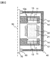
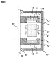
- the perspective view of the axial gap type rotary electric machine of embodiment of this invention Sectional drawing of the axial gap type rotary electric machine of embodiment of this invention.
- FIGS. 1 and 2 are perspective views for explaining the basic configuration of a two-rotor type axial gap rotating electrical machine to which the present invention is applied.
- the axial gap type rotating electrical machine 1 is arranged so that a pair of disk-shaped rotors 10 face each other in the direction of the rotation axis 50, and a predetermined gap is interposed between the pair of rotors 10.
- the stator 20 is sandwiched.
- the stator 20 includes a plurality of cores 22 arranged in the circumferential direction and coils 21 wound around the cores, and is held on the housing 40 by, for example, a resin mold or a mechanical part (not shown).
- the core 21 is composed of a laminated body of magnetic thin plates such as electromagnetic steel plates and amorphous foil strips, and the magnetic thin plates are insulated by insulating layers.
- the rotor 10 includes a yoke 12 having a recess in the axial direction, and a rotor core 13 disposed in each recess.
- the rotor core 13 is installed in the concave portion of the yoke 12 by adhesion, for example.
- the present invention is not limited to the above-described two-rotor axial gap type rotating electrical machine.
- a pair of stators are arranged so as to face each other in the axial direction, and the rotor is interposed through a predetermined gap.
- It can also be applied to a two-stator type axial gap type rotating electrical machine in which a stator is arranged and a one-rotor one-stator type axial gap type rotating electrical machine in which one stator and a rotor are arranged with a predetermined gap. Needless to say.
- embodiments relating to the rotor structure will be described.
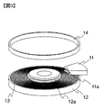
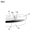
- Example (1) 2 to 4 show the rotor structure of the axial gap type rotating electric machine according to the first embodiment.
- the protrusion 12 a is provided on the inner diameter side of the yoke 12, and the notch 11 a is provided on the inner diameter side of the magnet 11.
- the magnet 11 is inserted from the outer diameter side and arranged so that the notch 11a fits into the protrusion 12a.
- an outer ring 14 is provided on the outer diameter side of the magnet 11.
- the magnet 11 and the rotor core 13 may be fixed by an adhesive force of an adhesive, for example, in addition to the attractive force of the magnet.
- the notch 11a of the magnet 11 is fitted to the protrusion 12a provided on the yoke 12, so that the rotating electrical machine is driven. It is possible to prevent the magnet from being pulled off in the axial direction (stator direction). Further, the positioning accuracy in the axial direction can be increased by fitting the protrusion 12a and the notch 11a. Furthermore, since the protrusion 12a and the notch 11a are provided in the middle of the side surface along the direction of the rotation axis 50 of the magnet 11, a larger facing area between the magnet 11 and the core 22 is secured, and high output is maintained. The holding strength against the axial attractive force of the magnet can be ensured.
- the position where the protrusion 12a and the notch 11a are provided is preferably approximately in the middle of the side surface along the direction of the rotation axis 50 of the magnet 11 from the viewpoint of holding strength, but the present invention is not limited to this.
- the protrusions 12a are provided on the entire circumference, the holding strength against the axial attractive force of the magnet can be further ensured.
- this invention is not restricted to this, You may provide the protrusion 12a partially in the circumferential direction.
- independent protrusions 12 a may be provided in accordance with the number of divisions of the magnet 11, the notches 11 a corresponding to the protrusions 12 may be provided, and the notches 11 a of the magnet 11 may be fitted into the protrusions 12 a. Good. Thereby, the positioning accuracy in the axial direction can be increased.
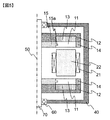
- FIG. 5 shows a rotor structure of the axial gap type rotating electric machine according to the second embodiment.
- an inner peripheral ring 15 is provided on the inner peripheral side.
- a protrusion 15 a is provided on the inner ring 15, and a notch 11 a provided in the magnet 11 is fitted and arranged.
- the inner ring 15 and the protrusion 15a can be configured by separate members, the manufacturability when the protrusion 15a is manufactured is improved.
- the inner ring 15 and the protrusion 15a are formed of separate members, for example, by using a high-strength member, it is possible to improve the strength against tensile force in the axial direction.
- the inner ring 15 and the protrusion 15a as a low-loss member, it is possible to reduce the loss caused by the leakage magnetic flux of the magnet 11 or the magnetic flux generated by the coil 21.
- the material of the member can be changed according to the characteristics of the rotating electrical machine.
- FIG. 6 shows a rotor structure of an axial gap type rotating electric machine according to the third embodiment.
- the notch 11a is provided on the outer diameter side of the magnet 11, and the protrusion 14a for fitting with the notch 11a is provided on the outer ring 14.
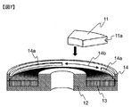
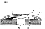
- FIGS. 7 to 9 show an example of an assembling method that makes it possible to assemble all the magnets and realize this embodiment without dividing the outer ring.
- a part of the protrusion 14a provided on the outer peripheral ring 14 is removed (the portion shown in FIG. 14b).
- the width of the protrusion removing portion 14b is configured to be the same as or larger than the width of the magnet 11 on the outer diameter side.
- the magnet 11 is inserted into the protrusion removal portion 14b from the axial direction, and then slid in the circumferential direction with the notch 11a and the protrusion 14a fitted. It is possible to install all the magnets by repeating the same method for all the magnets.
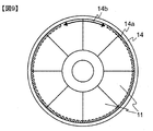
- FIG. 9 shows the structure of the rotor assembled as described above. As shown in the figure, when all the magnets are assembled, by arranging the two magnets 11 in the protrusion removing portion 14b, the protrusions 14a are fitted to all the magnets 11.
- the magnet 11 can be assembled without dividing the outer ring 14. Further, by fitting the notch 11a and the protrusion 14a on the outer diameter side of the magnet 11, it is possible to secure a large area for fitting compared to the structures shown in the first and second embodiments. The holding strength against the tensile force in the axial direction can be improved.
Landscapes
- Engineering & Computer Science (AREA)
- Power Engineering (AREA)
- Permanent Field Magnets Of Synchronous Machinery (AREA)
- Permanent Magnet Type Synchronous Machine (AREA)
- Iron Core Of Rotating Electric Machines (AREA)
Abstract
L'invention concerne une structure de rotor pour une machine électrique tournante à entrefer axial capable de fixer la résistance pour maintenir un aimant contre une force d'attraction axiale sans provoquer de réduction de la surface de l'aimant et d'augmentation de la longueur de l'entrefer. La présente invention concerne une machine électrique tournante à entrefer axial dans laquelle sont agencés un stator et un rotor dans la direction de l'axe de rotation, un entrefer étant prévu entre eux, une encoche étant ménagée du côté diamètre interne ou du côté circonférentiel externe d'un aimant disposé dans le rotor, et étant ménagée dans une position intermédiaire dans l'aimant dans la direction axiale, et une saillie devant être ajustée dans l'encoche de l'aimant est ménagée dans un étrier qui maintient l'aimant.
Applications Claiming Priority (2)
| Application Number | Priority Date | Filing Date | Title |
|---|---|---|---|
| JP2016076266A JP6685166B2 (ja) | 2016-04-06 | 2016-04-06 | アキシャルギャップ型回転電機 |
| JP2016-076266 | 2016-04-06 |
Publications (1)
| Publication Number | Publication Date |
|---|---|
| WO2017175461A1 true WO2017175461A1 (fr) | 2017-10-12 |
Family
ID=60000301
Family Applications (1)
| Application Number | Title | Priority Date | Filing Date |
|---|---|---|---|
| PCT/JP2017/003507 Ceased WO2017175461A1 (fr) | 2016-04-06 | 2017-02-01 | Machine électrique tournante à entrefer axial |
Country Status (3)
| Country | Link |
|---|---|
| JP (1) | JP6685166B2 (fr) |
| TW (1) | TWI648939B (fr) |
| WO (1) | WO2017175461A1 (fr) |
Families Citing this family (1)
| Publication number | Priority date | Publication date | Assignee | Title |
|---|---|---|---|---|
| JP7139138B2 (ja) * | 2018-04-18 | 2022-09-20 | 株式会社日立産機システム | アキシャルギャップ型回転電機 |
Citations (2)
| Publication number | Priority date | Publication date | Assignee | Title |
|---|---|---|---|---|
| JPS617275U (ja) * | 1984-06-18 | 1986-01-17 | 三洋電機株式会社 | 小型モ−タのロ−タ |
| JP2006304592A (ja) * | 2005-04-22 | 2006-11-02 | Isa Innovation Sa | 永久磁石を固定するシステム |
Family Cites Families (4)
| Publication number | Priority date | Publication date | Assignee | Title |
|---|---|---|---|---|
| JP2006014520A (ja) * | 2004-06-28 | 2006-01-12 | Toshiba Corp | 回転電機の外転型回転子 |
| EP2081276A1 (fr) * | 2008-01-21 | 2009-07-22 | Marco Cipriani | Dispositif électromagnétique doté d'un fonctionnement réversible générateur/moteur |
| WO2009133941A1 (fr) * | 2008-04-30 | 2009-11-05 | 日本電産コパル株式会社 | Moteur oscillant |
| CN106464111B (zh) * | 2014-04-14 | 2019-09-27 | 株式会社日立产机系统 | 轴向气隙型旋转电机 |
-
2016
- 2016-04-06 JP JP2016076266A patent/JP6685166B2/ja active Active
-
2017
- 2017-02-01 WO PCT/JP2017/003507 patent/WO2017175461A1/fr not_active Ceased
- 2017-03-08 TW TW106107593A patent/TWI648939B/zh not_active IP Right Cessation
Patent Citations (2)
| Publication number | Priority date | Publication date | Assignee | Title |
|---|---|---|---|---|
| JPS617275U (ja) * | 1984-06-18 | 1986-01-17 | 三洋電機株式会社 | 小型モ−タのロ−タ |
| JP2006304592A (ja) * | 2005-04-22 | 2006-11-02 | Isa Innovation Sa | 永久磁石を固定するシステム |
Also Published As
| Publication number | Publication date |
|---|---|
| TW201737596A (zh) | 2017-10-16 |
| TWI648939B (zh) | 2019-01-21 |
| JP6685166B2 (ja) | 2020-04-22 |
| JP2017189019A (ja) | 2017-10-12 |
Similar Documents
| Publication | Publication Date | Title |
|---|---|---|
| CN107408852B (zh) | 转子、旋转电机以及转子的制造方法 | |
| CN107005103B (zh) | 旋转电机用定子铁芯、旋转电机及旋转电机的制造方法 | |
| JP5958502B2 (ja) | 回転子およびそれを用いた回転電機 | |
| JP6640621B2 (ja) | 電動機用ロータ、およびブラシレスモータ | |
| JP6055725B2 (ja) | 回転子および回転子を用いたアキシャル型回転電機 | |
| US9143014B2 (en) | Rotor, dynamo-electric machine having the rotor and rotor manufacturing method | |
| WO2014034344A1 (fr) | Machine électrique tournante | |
| US9190878B2 (en) | Rotor including anti-rotation feature for multi-pole structure | |
| CN102457114A (zh) | 旋转电机 | |
| JPWO2017061305A1 (ja) | 回転子および回転電機 | |
| CN107112831A (zh) | 电机 | |
| CN112542905A (zh) | 轴向间隙电机 | |
| WO2017212575A1 (fr) | Moteur à aimants permanents | |
| JP2014045634A (ja) | ロータ及びこのロータを備える回転電機 | |
| JP2018057155A (ja) | 回転電機の回転子 | |
| JPWO2018131402A1 (ja) | 永久磁石埋込型の回転子およびこれを備えた電動機 | |
| JP2014220879A (ja) | 永久磁石回転電機 | |
| JP6685166B2 (ja) | アキシャルギャップ型回転電機 | |
| JP2022011327A (ja) | 永久磁石回転電機および回転子 | |
| JP2010011621A (ja) | 回転電機用エンドプレート | |
| JP2015220950A (ja) | 回転電機 | |
| JP2012244808A (ja) | 回転電機のロータ | |
| JP2017046386A (ja) | 永久磁石電動機 | |
| KR20140118806A (ko) | 박형 모터 | |
| JP2013169131A (ja) | ブラシレスモータ用ロータ及び電動パワーステアリング装置 |
Legal Events
| Date | Code | Title | Description |
|---|---|---|---|
| NENP | Non-entry into the national phase |
Ref country code: DE |
|
| 121 | Ep: the epo has been informed by wipo that ep was designated in this application |
Ref document number: 17778840 Country of ref document: EP Kind code of ref document: A1 |
|
| 122 | Ep: pct application non-entry in european phase |
Ref document number: 17778840 Country of ref document: EP Kind code of ref document: A1 |