WO2017175678A1 - 異常検出装置、異常検出方法及び異常検出システム - Google Patents
異常検出装置、異常検出方法及び異常検出システム Download PDFInfo
- Publication number
- WO2017175678A1 WO2017175678A1 PCT/JP2017/013639 JP2017013639W WO2017175678A1 WO 2017175678 A1 WO2017175678 A1 WO 2017175678A1 JP 2017013639 W JP2017013639 W JP 2017013639W WO 2017175678 A1 WO2017175678 A1 WO 2017175678A1
- Authority
- WO
- WIPO (PCT)
- Prior art keywords
- opening
- opening degree
- value
- vehicle
- abnormality
- Prior art date
- Legal status (The legal status is an assumption and is not a legal conclusion. Google has not performed a legal analysis and makes no representation as to the accuracy of the status listed.)
- Ceased
Links
Images



Classifications
-
- F—MECHANICAL ENGINEERING; LIGHTING; HEATING; WEAPONS; BLASTING
- F02—COMBUSTION ENGINES; HOT-GAS OR COMBUSTION-PRODUCT ENGINE PLANTS
- F02D—CONTROLLING COMBUSTION ENGINES
- F02D41/00—Electrical control of supply of combustible mixture or its constituents
- F02D41/22—Safety or indicating devices for abnormal conditions
- F02D41/221—Safety or indicating devices for abnormal conditions relating to the failure of actuators or electrically driven elements
-
- F—MECHANICAL ENGINEERING; LIGHTING; HEATING; WEAPONS; BLASTING
- F02—COMBUSTION ENGINES; HOT-GAS OR COMBUSTION-PRODUCT ENGINE PLANTS
- F02B—INTERNAL-COMBUSTION PISTON ENGINES; COMBUSTION ENGINES IN GENERAL
- F02B39/00—Component parts, details, or accessories relating to, driven charging or scavenging pumps, not provided for in groups F02B33/00 - F02B37/00
- F02B39/16—Other safety measures for, or other control of, pumps
-
- F—MECHANICAL ENGINEERING; LIGHTING; HEATING; WEAPONS; BLASTING
- F02—COMBUSTION ENGINES; HOT-GAS OR COMBUSTION-PRODUCT ENGINE PLANTS
- F02D—CONTROLLING COMBUSTION ENGINES
- F02D29/00—Controlling engines, such controlling being peculiar to the devices driven thereby, the devices being other than parts or accessories essential to engine operation, e.g. controlling of engines by signals external thereto
- F02D29/02—Controlling engines, such controlling being peculiar to the devices driven thereby, the devices being other than parts or accessories essential to engine operation, e.g. controlling of engines by signals external thereto peculiar to engines driving vehicles; peculiar to engines driving variable pitch propellers
-
- F—MECHANICAL ENGINEERING; LIGHTING; HEATING; WEAPONS; BLASTING
- F02—COMBUSTION ENGINES; HOT-GAS OR COMBUSTION-PRODUCT ENGINE PLANTS
- F02M—SUPPLYING COMBUSTION ENGINES IN GENERAL WITH COMBUSTIBLE MIXTURES OR CONSTITUENTS THEREOF
- F02M26/00—Engine-pertinent apparatus for adding exhaust gases to combustion-air, main fuel or fuel-air mixture, e.g. by exhaust gas recirculation [EGR] systems
- F02M26/45—Sensors specially adapted for EGR systems
- F02M26/48—EGR valve position sensors
-
- F—MECHANICAL ENGINEERING; LIGHTING; HEATING; WEAPONS; BLASTING
- F02—COMBUSTION ENGINES; HOT-GAS OR COMBUSTION-PRODUCT ENGINE PLANTS
- F02M—SUPPLYING COMBUSTION ENGINES IN GENERAL WITH COMBUSTIBLE MIXTURES OR CONSTITUENTS THEREOF
- F02M26/00—Engine-pertinent apparatus for adding exhaust gases to combustion-air, main fuel or fuel-air mixture, e.g. by exhaust gas recirculation [EGR] systems
- F02M26/49—Detecting, diagnosing or indicating an abnormal function of the EGR system
-
- G—PHYSICS
- G05—CONTROLLING; REGULATING
- G05B—CONTROL OR REGULATING SYSTEMS IN GENERAL; FUNCTIONAL ELEMENTS OF SUCH SYSTEMS; MONITORING OR TESTING ARRANGEMENTS FOR SUCH SYSTEMS OR ELEMENTS
- G05B19/00—Program-control systems
- G05B19/02—Program-control systems electric
- G05B19/04—Program control other than numerical control, i.e. in sequence controllers or logic controllers
- G05B19/048—Monitoring; Safety
-
- G—PHYSICS
- G07—CHECKING-DEVICES
- G07C—TIME OR ATTENDANCE REGISTERS; REGISTERING OR INDICATING THE WORKING OF MACHINES; GENERATING RANDOM NUMBERS; VOTING OR LOTTERY APPARATUS; ARRANGEMENTS, SYSTEMS OR APPARATUS FOR CHECKING NOT PROVIDED FOR ELSEWHERE
- G07C5/00—Registering or indicating the working of vehicles
- G07C5/008—Registering or indicating the working of vehicles communicating information to a remotely located station
-
- G—PHYSICS
- G07—CHECKING-DEVICES
- G07C—TIME OR ATTENDANCE REGISTERS; REGISTERING OR INDICATING THE WORKING OF MACHINES; GENERATING RANDOM NUMBERS; VOTING OR LOTTERY APPARATUS; ARRANGEMENTS, SYSTEMS OR APPARATUS FOR CHECKING NOT PROVIDED FOR ELSEWHERE
- G07C5/00—Registering or indicating the working of vehicles
- G07C5/08—Registering or indicating performance data other than driving, working, idle, or waiting time, with or without registering driving, working, idle or waiting time
- G07C5/0816—Indicating performance data, e.g. occurrence of a malfunction
-
- F—MECHANICAL ENGINEERING; LIGHTING; HEATING; WEAPONS; BLASTING
- F02—COMBUSTION ENGINES; HOT-GAS OR COMBUSTION-PRODUCT ENGINE PLANTS
- F02D—CONTROLLING COMBUSTION ENGINES
- F02D41/00—Electrical control of supply of combustible mixture or its constituents
- F02D41/22—Safety or indicating devices for abnormal conditions
- F02D2041/228—Warning displays
-
- F—MECHANICAL ENGINEERING; LIGHTING; HEATING; WEAPONS; BLASTING
- F02—COMBUSTION ENGINES; HOT-GAS OR COMBUSTION-PRODUCT ENGINE PLANTS
- F02D—CONTROLLING COMBUSTION ENGINES
- F02D2200/00—Input parameters for engine control
- F02D2200/02—Input parameters for engine control the parameters being related to the engine
- F02D2200/04—Engine intake system parameters
- F02D2200/0404—Throttle position
-
- F—MECHANICAL ENGINEERING; LIGHTING; HEATING; WEAPONS; BLASTING
- F02—COMBUSTION ENGINES; HOT-GAS OR COMBUSTION-PRODUCT ENGINE PLANTS
- F02D—CONTROLLING COMBUSTION ENGINES
- F02D41/00—Electrical control of supply of combustible mixture or its constituents
- F02D41/0025—Controlling engines characterised by use of non-liquid fuels, pluralities of fuels, or non-fuel substances added to the combustible mixtures
- F02D41/0047—Controlling exhaust gas recirculation [EGR]
- F02D41/0077—Control of the EGR valve or actuator, e.g. duty cycle, closed loop control of position
-
- Y—GENERAL TAGGING OF NEW TECHNOLOGICAL DEVELOPMENTS; GENERAL TAGGING OF CROSS-SECTIONAL TECHNOLOGIES SPANNING OVER SEVERAL SECTIONS OF THE IPC; TECHNICAL SUBJECTS COVERED BY FORMER USPC CROSS-REFERENCE ART COLLECTIONS [XRACs] AND DIGESTS
- Y02—TECHNOLOGIES OR APPLICATIONS FOR MITIGATION OR ADAPTATION AGAINST CLIMATE CHANGE
- Y02T—CLIMATE CHANGE MITIGATION TECHNOLOGIES RELATED TO TRANSPORTATION
- Y02T10/00—Road transport of goods or passengers
- Y02T10/10—Internal combustion engine [ICE] based vehicles
- Y02T10/40—Engine management systems
Definitions
- the present disclosure relates to an abnormality detection device, an abnormality detection method, and an abnormality detection system that detect an abnormality of a valve of a vehicle.
- Patent Document 1 discloses a technique for determining that a failure has occurred when the terminal voltage of a valve greatly deviates from a predetermined normal value.
- the presence / absence of abnormality is determined by comparing one measurement result with a normal value. Therefore, if the measurement results vary due to the influence of the vehicle running condition or the surrounding environment, there is a problem that it may be erroneously determined that an abnormality has occurred even though no abnormality has occurred. It was.
- the present disclosure provides an abnormality detection device, an abnormality detection method, and an abnormality detection system that can improve the accuracy of valve abnormality detection.
- the abnormality detection device acquires a plurality of opening degree data indicating opening degrees of valves provided in a vehicle, which are measured in a predetermined period, and the acquisition part acquires An integration unit that calculates an integrated value of the difference by integrating a plurality of differences between a plurality of actual opening values indicated by the plurality of opening data and a target opening value of the valve, and the integration unit integrates And a determination unit that determines that the vehicle is abnormal when the integrated value is greater than a predetermined value.
- the integration unit calculates the integrated value obtained by integrating the difference between the plurality of opening actual values measured in the predetermined period and the opening target value as a reference period.
- the normalized integrated value may be calculated by converting to the integrated value, and the determination unit may determine that the vehicle is abnormal when the normalized integrated value is greater than the predetermined value.
- the abnormality detection device calculates an integrated value calculated based on a plurality of differences between the plurality of opening actual values and the opening target values measured in a plurality of the predetermined periods.
- the vehicle further includes a storage unit that stores the plurality of opening actual values in association with the measured periods, and the determination unit is configured to change the vehicle based on a change tendency of the plurality of integrated values in the plurality of predetermined periods. The abnormality may be determined.
- the acquisition unit acquires the opening degree data in association with state information indicating the state of the vehicle, and the integration unit corresponds to the plurality of opening actual values and the state information.
- the integrated value of the differences may be calculated by integrating the plurality of differences with the opening target value.
- the abnormality detection method includes a step of acquiring a plurality of opening degree data indicating an opening degree of a valve provided in a vehicle, which is measured in a predetermined period, and is acquired by a computer.
- a step of calculating an integrated value of the difference by integrating a plurality of differences between a plurality of actually measured opening values indicated by the plurality of opening data and the target opening value of the valve; and the integrated integrated value Determining that there is an abnormality in the vehicle.
- An abnormality detection system includes an opening degree detection device mounted on a vehicle, an abnormality detection device that detects an abnormality of the valve based on the opening degree of the valve detected by the opening degree detection device, and
- the opening detection device includes a detection unit for detecting the opening of the valve and opening data indicating the opening to the abnormality detection device via a wireless communication line.
- a communication unit for transmitting, an acquisition unit for acquiring a plurality of opening degree data indicating an opening degree of a valve provided in the vehicle, measured in a predetermined period, and the plurality of acquisition units acquired by the acquisition unit
- An integration unit that calculates an integrated value of the difference by integrating a plurality of differences between a plurality of actual opening values indicated by the opening data and a target opening value of the valve, and the integration integrated by the integration unit If the value is greater than the predetermined value, Serial having a determination section for determining that there is an abnormality in the vehicle.
- FIG. 1 is a diagram illustrating a configuration of an abnormality detection system according to the present embodiment.
- FIG. 2 is a diagram showing the configuration of the intake / exhaust system of the vehicle.
- FIG. 3 is a diagram illustrating a configuration of the abnormality detection apparatus.
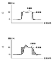
- FIG. 4A and FIG. 4B are diagrams for explaining the integrated value of the differences.
- FIG. 5A and FIG. 5B are diagrams for explaining a method in which the determination unit performs determination based on the change tendency of the integrated value.
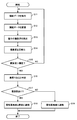
- FIG. 6 is a flowchart of an operation in which the abnormality detection device detects an abnormality of the EGR valve.
- FIG. 1 is a diagram illustrating a configuration of an abnormality detection system S according to the present embodiment.
- the abnormality detection system S is a system that detects an abnormality of the vehicle T in conjunction with the abnormality detection device 1 and the vehicle T.
- the abnormality detection device 1 is installed in a data collection center C that collects data indicating various vehicle T states.
- the abnormality detection device 1 is connected to a plurality of vehicles T via wireless communication lines, and receives data indicating the state of the vehicle T from each vehicle T at a predetermined time interval.
- the abnormality detection device 1 detects an abnormality of the vehicle T based on various data received from the vehicle T.
- the anomaly detection device 1 is connected to a computer installed in a management base station M that manages the vehicle T via a network (for example, the Internet).
- the management base station M is a facility of a company that owns the vehicle T or a company that maintains the vehicle T, for example.
- the staff of the management base station M receives a notification that an abnormality has occurred in the vehicle T from the abnormality detection device 1, it notifies the driver of the vehicle T that an abnormality has occurred, or the maintenance of the vehicle T. By doing this, you can prevent serious accidents.
- valves are mounted on the vehicle T of the present embodiment.
- the vehicle T includes an intake throttle valve, an EGR valve (Exhaust Gas Recirculation valve), a blow-off valve mounted on a turbocharger, and a rail pressure control valve mounted on an intake / exhaust system.
- EGR valve Exhaust Gas Recirculation valve
- blow-off valve mounted on a turbocharger
- rail pressure control valve mounted on an intake / exhaust system.
- an operation when an abnormality of the EGR valve is detected among the valves mounted on the vehicle T will be described.
- the present disclosure can be applied to any valve mounted on the vehicle T.
- FIG. 2 is a diagram showing the configuration of the intake / exhaust system 2 of the vehicle T.
- An intake passage 21 is connected to the intake manifold 20a of the engine 20, and an exhaust passage 22 is connected to the exhaust manifold 20b.
- a compressor 30 a of the variable nozzle turbo 30, a throttle valve 23, and an intercooler 24 are provided in order from the upstream side, and a turbine 30 b of the variable nozzle turbo 30 is provided in the exhaust passage 22.
- An intake air flow sensor 40 is provided on the intake upstream side of the compressor 30a.
- An intake pressure sensor 41 is provided in the intake manifold 20a.
- the detected value (hereinafter referred to as intake air amount) of the intake flow sensor 40 and the detected value (hereinafter referred to as intake pressure) of the intake pressure sensor 41 are input to an electrically connected ECU (Engine Control Unit) 60.
- the variable nozzle turbo 30 includes a compressor 30a provided in the intake passage 21, a turbine 30b provided in the exhaust passage 22, and a variable nozzle 30c provided in the turbine 30b.
- the compressor 30a and the turbine 30b are connected via a rotating shaft.
- the EGR device 50 includes an EGR passage 51 that connects the exhaust passage 22 upstream of the turbine 30b and the intake passage 21 upstream of the intercooler 24, an EGR valve 52 that adjusts the flow rate of EGR gas, An EGR cooler 53 that cools the EGR gas and an opening degree sensor 54 that detects the opening degree of the EGR valve 52 are provided.
- the flow rate of EGR gas in the EGR device 50 is adjusted by controlling the opening degree of the EGR valve 52 according to the opening degree control signal output from the ECU 60.
- the ECU 60 performs various controls such as fuel injection of the engine 20 and control of the opening degree of the EGR valve 52 included in the EGR device 50.
- the ECU 60 includes a CPU (Central Processing Unit), a ROM (Read Only Memory), a RAM (Random Access Memory), an input port, an output port, and the like.
- CPU Central Processing Unit
- ROM Read Only Memory
- RAM Random Access Memory
- the ECU 60 associates the opening degree data indicating the opening degree of the EGR valve 52 detected by the opening degree sensor 54 with the time when the opening degree is measured and the value of the opening degree control signal when the opening degree is measured. To be stored in the RAM. For example, the ECU 60 measures the opening degree data measured at the timing when the opening degree of the EGR valve 52 is instructed to be 0% and the timing when the opening degree of the EGR valve 52 is instructed to be 100%. The opening degree data is distinguished and stored in the RAM.
- the communication unit 70 is a wireless communication unit for transmitting and receiving data via a wireless communication line.
- the communication unit 70 transmits various data acquired from the ECU 60 to the abnormality detection device 1, and receives various data transmitted by the abnormality detection device 1 and notifies the ECU 60 of the various data.
- the communication unit 70 transmits, for example, opening degree data temporarily stored by the ECU 60 and indicating the opening degree detected by the opening degree sensor 54 over a predetermined period to the abnormality detection device 1 at predetermined time intervals. At this time, the communication unit 70 transmits the opening degree data in association with the control content (for example, the set value of the opening degree) indicated by the opening degree control information at the time when the opening degree is measured.
- the opening degree sensor 54, the ECU 60, and the communication unit 70 work together to function as an opening degree detection device.
- the communication unit 70 transmits the opening degree data to the abnormality detecting device 1 at a predetermined time interval so that the abnormality detecting device 1 can measure the actual opening value over a predetermined period. It is possible to detect that an abnormality has occurred in the EGR valve 52 based on the integrated value of the difference between the target value and the target value.
- FIG. 3 is a diagram illustrating a configuration of the abnormality detection apparatus 1.
- the abnormality detection device 1 includes a first communication unit 11, a second communication unit 12, a storage unit 13, and a control unit 14.
- the control unit 14 includes an opening degree acquisition unit 141, an integration unit 142, a determination unit 143, and an abnormality notification unit 144.
- the first communication unit 11 is a wireless communication unit for transmitting and receiving data to and from the intake / exhaust system 2 via a wireless communication line.
- the 1st communication part 11 receives the electromagnetic wave containing various data, such as opening degree data, from the several vehicle T registered previously, for example via the computer of a packet communication network.
- the first communication unit 11 extracts the opening degree data included in the received radio wave, and inputs the opening degree data to the opening degree obtaining unit 141.
- the second communication unit 12 is a communication controller for transmitting and receiving data to and from the computer of the management base station M via the Internet.
- the determination unit 143 detects an abnormality of the EGR valve 52 of the vehicle T
- the second communication unit 12 transmits a message notifying the abnormality to the computer of the management base station M that manages the vehicle T.
- the storage unit 13 is a storage medium including a ROM, a RAM, a hard disk, and the like.
- the storage unit 13 stores a program executed by the control unit 14.
- the storage unit 13 stores a target value of the opening used by the determination unit 143 to detect an abnormality of the EGR valve 52. Since the target value of the opening degree differs for each vehicle type of the vehicle T, the storage unit 13 stores the target value in association with the vehicle type of the vehicle T, for example.
- storage part 13 may update the target value of an opening regularly based on the opening degree data acquired from many vehicles T of the same vehicle type.
- the storage unit 13 stores the transmitted opening degree data in association with the identification information unique to each vehicle T and the time when the opening degree is measured.
- the storage unit 13 stores an integrated value that is calculated every predetermined period (for example, one day) by an integration unit 142 described later.
- the control unit 14 is, for example, a CPU, and functions as an opening degree acquisition unit 141, an integration unit 142, a determination unit 143, and an abnormality notification unit 144 by executing a program stored in the storage unit 13.
- the opening degree acquisition unit 141 displays opening degree data that is measured at a plurality of different times and indicates an actual value of the opening degree in a state where the EGR valve 52 is set to a predetermined opening degree. get. Since the opening data is sent from the vehicle T in association with the value of the opening control information at the time when the opening is measured, the opening acquisition unit 141 uses the acquired opening data as the opening.
- the measured time and opening are stored in the storage unit 13 in association with the value of the opening control information at the time when the opening is measured.
- the integrating unit 142 calculates the integrated value of the difference by integrating the difference between the plurality of actual opening values indicated by the plurality of opening data acquired by the opening acquiring unit 141 and the opening target value of the EGR valve 52. To do.
- the above-mentioned difference may be calculated as an absolute value of the difference between the opening actual measurement value and the opening target value, or may be calculated as a difference including a negative sign.
- FIG. 4A and FIG. 4B are diagrams for explaining the integrated value of the differences.
- the horizontal axis in FIG. 4 indicates the date and time when the opening is measured, and the vertical axis indicates the opening.
- the target opening degree value corresponds to the value of the opening degree control information. In FIG. 4, the target value changes from the opening degree 0% (completely closed state) to the opening degree 50% (half open state). is doing.
- the EGR valve 52 requires a response time from when the value of the opening degree control information changes until the opening degree actually changes. As a result, there is a difference between the actually measured opening value and the target opening value in the hatched region in FIGS. 4 (a) and 4 (b).
- the integration unit 142 calculates, for each opening degree data, a difference value between the actual opening degree value indicated by the opening degree data and the opening degree target value, and adds the difference value with respect to the actual opening degree value measured within a predetermined period. As a result, an integrated value of the difference is calculated.
- the integrated value calculated in this way by the integrating unit 142 corresponds to the area of the region indicated by the oblique lines in FIG.
- FIG. 4B Comparing FIG. 4A and FIG. 4B, it can be seen that the area of the hatched area in FIG. 4B is larger than the area of the hatched area in FIG. In FIG. 4B, it is estimated that the response time with respect to the change in the value of the opening degree control information is longer than the response time in FIG. 4A, and the EGR valve 52 is deteriorated. In such a case, the integrated value in FIG. 4B is larger than the integrated value in FIG.
- the integration unit 142 inputs the calculated integration value to the determination unit 143.
- the period during which the accumulating unit 142 accumulates the difference is arbitrary.
- the integration unit 142 integrates the difference in units of one day, and notifies the determination unit 143 of the integration value in units of one day. Then, when the day changes, the integration unit 142 initializes the integration value and calculates a new integration value.
- the determination unit 143 detects an abnormality of the EGR valve 52 based on the integrated value of the differences between the plurality of actual measured opening values and the target opening value measured during a predetermined period. For example, the determination unit 143 compares the integrated value with a predetermined threshold, and determines that an abnormality has occurred in the EGR valve 52 when the integrated value is larger than the threshold.
- the abnormality notification unit 144 notifies the computer of the management base station M that an abnormality has occurred when the determination unit 143 determines that an abnormality has occurred in the EGR valve 52.
- the abnormality notification unit 144 includes an abnormality including identification information of the vehicle T in which the abnormality has occurred, the address of the computer of the management base station M that manages the vehicle T, and the fact that the abnormality has occurred.
- a notification message is created and transmitted via the second communication unit 12 to notify the computer of the management base station M that an abnormality has occurred in the EGR valve 52.
- the abnormality detection device 1 determines the presence or absence of abnormality based on the integrated value of the difference between the actually measured opening value and the opening target value.
- the time that can be measured is not constant. For example, when the vehicle T travels a long distance, the abnormality detection device 1 can acquire an actual opening degree value measured over a long time. However, when the vehicle T travels only a short distance, an abnormality detection is performed. The device 1 can only acquire the actual opening value for a short time. As described above, if the number of actually measured opening values to be integrated varies, the accuracy of abnormality detection decreases.
- the integrating unit 142 calculates the integrated value obtained by integrating the differences between the plurality of actually measured opening values measured during the period in which the vehicle T is traveling and the opening target value as the integrated value of the reference period.
- the normalized integrated value is calculated by converting to.
- the determination unit 143 determines that the vehicle is abnormal when the normalized integrated value is greater than a predetermined threshold value. For example, when the reference period is 30 minutes and the opening degree acquisition unit 141 acquires the actual opening value for 2 hours, the integrating unit 142 calculates the integrated value obtained from the actual opening value for 2 hours for 4 minutes. Therefore, the normalized integrated value converted into the reference period is calculated.
- the abnormality detection device 1 not only determines the presence / absence of abnormality for each predetermined period (for example, one day) for which the integration unit 142 calculates the integrated value, but also includes a plurality of integrated values calculated by the integration unit 142 over a plurality of periods. The presence or absence of an abnormality may be determined based on the change tendency.
- the storage unit 13 uses the integrated values calculated based on the plurality of differences between the plurality of actually measured opening values measured in the plurality of periods and the target opening value as the plurality of actually measured opening values. The value is stored in association with the measured period.
- the determination part 143 determines the abnormality of a vehicle based on the change tendency of several integrated value in several periods (for example, the last one month).
- FIG. 5A and FIG. 5B are diagrams for explaining a method in which the determination unit 143 performs determination based on the change tendency of the integrated value.
- the horizontal axis in FIG. 5 indicates the day on which the integrated value is calculated, and the vertical axis indicates the integrated value.
- FIG. 5A shows how the integrated value changes in a state where no abnormality has occurred in the EGR valve 52.
- the determination unit 143 receives the notification of the integrated value from the integration unit 142
- the determination unit 143 reads the integrated value calculated within the latest determination period from the storage unit 13 and identifies the change tendency of the integrated value.
- the determination unit 143 specifies the amount of change in the integrated value within the determination period, that is, the slope of the straight line L1 shown in FIG.
- the determination unit 143 can determine the straight line L1 by, for example, obtaining a regression line based on a plurality of integrated values within the determination period.
- the determination unit 143 detects an abnormality by comparing the change tendency of the integrated value within the latest determination period with the normal range. Specifically, the determination unit 143 determines whether or not the identified change tendency is included in the normal range indicated by the normal range information stored in the storage unit 13. For example, the determination unit 143 determines that the EGR valve 52 is normal when the slope of the straight line L1 specified as the change tendency is within a predetermined range, and the EGR valve 52 is abnormal when the slope of the straight line L1 is outside the normal range. It is determined that
- FIG. 5B shows how the integrated value changes in a state where the EGR valve 52 is abnormal.
- the slope of the straight line L2 specified by the determination unit 143 based on the integrated value within the determination period is larger than the slope of the straight line L1 shown in FIG.
- the determination unit 143 determines that an abnormality has occurred in the EGR valve 52. If the determination unit 143 determines that an abnormality has occurred, the determination unit 143 notifies the abnormality notification unit 144 of the identification information of the vehicle T that is associated with the integrated value that has been determined that an abnormality has occurred and that the abnormality has occurred.
- the determination unit 143 determines the presence / absence of abnormality based on the tendency of the integrated value to change over a long period of time as described above, the influence of component variation and temporary value change is suppressed, so that abnormality detection accuracy is achieved. Will improve.
- FIG. 6 is a flowchart of an operation in which the abnormality detection device 1 detects an abnormality of the EGR valve 52.
- the opening degree obtaining unit 141 obtains opening degree data transmitted from the vehicle T (S11). Whenever the opening degree data is obtained, the opening degree obtaining unit 141 associates the opening degree data with the identification information of the vehicle T and stores it in the storage unit 13 (S12).
- the integration unit 142 calculates the difference between the actual opening degree value indicated by the opening degree data and the opening degree target value stored in the storage unit 13. An integrated value is calculated (S13). Furthermore, the integrating unit 142 normalizes the calculated integrated value by converting it into an integrated value for a predetermined period (S14). Subsequently, the determination unit 143 determines whether or not there is an abnormality by comparing the integrated value with a predetermined threshold value (S15).
- determination unit 143 determines that no abnormality has occurred, returns the process to step S11, and waits until the next opening degree data is transmitted. If the integrated value is greater than the threshold value (YES in S15), determination unit 143 determines that an abnormality has occurred in EGR valve 52 (S16).
- the determination unit 143 determines whether the level of abnormality is a level that requires emergency response or a level that does not require emergency response.
- the level is notified to the abnormality notifying unit 144 (S17).
- the abnormality notification unit 144 receives a notification of occurrence of an urgent abnormality (for example, an abnormality that hinders driving)
- the abnormality notification unit 144 notifies both the management base station M and the vehicle T that the abnormality has occurred ( S18).
- the abnormality notification unit 144 receives a notification of occurrence of an abnormality that is not urgent (for example, an abnormality in which deterioration of a component is estimated)
- the abnormality notification unit 144 notifies only the management base station M that the abnormality has occurred ( S19).
- the opening sensor 54 measures the opening of the EGR valve 52, but means for measuring the opening of the EGR valve 52 is not limited to this. Since the intake air amount changes depending on the opening degree of the EGR valve 52, the vehicle T specifies the opening degree based on the intake air amount detected by the intake flow sensor 40, and the opening degree data indicating the specified opening degree is the abnormality detection device 1. May be sent to. Further, the vehicle T may transmit intake air amount data indicating the intake air amount to the abnormality detection device 1, and the abnormality detection device 1 may specify the opening degree based on the intake air amount data.
- the state of the vehicle when the opening degree data is measured is not considered, but the vehicle T indicates the state information indicating the state of the vehicle when the opening degree data is measured as the opening degree.
- the data may be transmitted to the abnormality detection device 1 in association with the data.
- the vehicle state includes, for example, a vehicle speed, an accelerator opening, a vehicle inclination, and the like.
- the storage unit 13 stores an opening target value in association with the state of the vehicle.
- the opening degree obtaining unit 141 obtains opening degree data in association with the state information indicating the state of the vehicle T.
- the integrating unit 142 calculates an integrated value by integrating the difference between the plurality of actual opening values received from the vehicle T and the target opening value corresponding to the state information.
- the integrating unit 142 calculates the normalized integrated value by converting the integrated value into the reference period.
- the integrating unit may normalize based on the number of times the opening degree control information has changed by a predetermined amount.
- the storage unit 13 stores the reference number of times when the opening degree changes from 0% to 50% and the reference number of times when the opening degree changes from 50% to 0%.
- the normalized integrated value is calculated by multiplying the calculated integrated value by the reference number / the actual number of times. Since the integrated value of the difference increases immediately after the opening degree is changed, the abnormality detection accuracy is improved by normalizing based on the number of times the opening degree is changed.
- the abnormality detection device 1 receives the opening degree data indicating the actual opening degree values measured at a plurality of different times from the vehicle T, and integrates the difference between the actual opening degree value and the target opening value. Calculate the value. And the abnormality detection apparatus 1 determines the presence or absence of abnormality by comparing an integrated value with a predetermined threshold value. By doing in this way, since the possibility that an abnormality is erroneously detected due to a temporary change in the opening degree is reduced, the detection accuracy of the abnormality can be improved.
- the abnormality detection device 1 normalizes the integrated value based on the period during which the opening is measured and the reference period. By doing so, the abnormality detection device 1 can determine the presence or absence of an abnormality by converting to the same reference period even if there is a variation in the period during which the opening is measured. Further improvement can be achieved.
- the abnormality detection device 1 can also determine the presence or absence of abnormality based on a change tendency of a plurality of integrated values calculated by the integrating unit 142 over a plurality of periods. By doing so, the influence of component variations and temporary value changes can be suppressed, so that the abnormality detection accuracy can be further improved.
- the abnormality detection device 1 installed in the data collection center C detects an abnormality in the EGR valve 52.
- the vehicle T is in an abnormality equivalent to the abnormality detection device 1 in the first embodiment.
- a detection device may be included to detect abnormality of various valves such as the EGR valve 52 in the vehicle T.
- the abnormality detection device of the vehicle T displays on the instrument panel that the abnormality has occurred and notifies the driver or an abnormality to the management base station. Or report the occurrence of
- the abnormality detection device According to the abnormality detection device, the abnormality detection method, and the abnormality detection system of the present disclosure, it is possible to improve the detection accuracy of the valve abnormality.
Landscapes
- Engineering & Computer Science (AREA)
- Chemical & Material Sciences (AREA)
- Combustion & Propulsion (AREA)
- Mechanical Engineering (AREA)
- General Engineering & Computer Science (AREA)
- General Physics & Mathematics (AREA)
- Physics & Mathematics (AREA)
- Analytical Chemistry (AREA)
- Automation & Control Theory (AREA)
- Testing And Monitoring For Control Systems (AREA)
- Combined Controls Of Internal Combustion Engines (AREA)
- Exhaust-Gas Circulating Devices (AREA)
- Control Of Vehicle Engines Or Engines For Specific Uses (AREA)
Abstract
異常検出装置(1)は、所定の期間において計測された、車両(T)に備えられたバルブの開度を示す複数の開度データを取得する開度取得部(141)と、開度取得部(141)が取得した複数の開度データが示す複数の開度実測値とバルブの開度目標値との複数の差分を積算することにより、差分の積算値を算出する積算部(142)と、積算部(142)が積算した積算値が所定の値より大きい場合、車両(T)に異常があると判定する判定部(143)と、を有する。
Description
本開示は、車両のバルブの異常を検出する異常検出装置、異常検出方法及び異常検出システムに関する。
車両のバルブの開度の測定値を判定値と比較することにより、バルブの不具合を検出する故障診断システムが知られている。特許文献1においては、バルブの端子電圧が、予め定められている正常値から大きく乖離している場合に、故障していると判断する技術が開示されている。
従来の技術においては、1回の測定結果を正常値と比較することにより、異常の有無を判定していた。したがって、車両の走行状態や周辺環境等の影響で測定結果にばらつきが発生した場合、異常が発生していないにもかかわらず、異常が発生したと誤判定してしまう場合があるという問題があった。
そこで、本開示は、バルブの異常の検出精度を向上させることができる異常検出装置、異常検出方法及び異常検出システムを提供する。
本開示の第1の態様の異常検出装置は、所定の期間において計測された、車両に備えられたバルブの開度を示す複数の開度データを取得する取得部と、前記取得部が取得した前記複数の開度データが示す複数の開度実績値と前記バルブの開度目標値との複数の差分を積算することにより、前記差分の積算値を算出する積算部と、前記積算部が積算した前記積算値が所定の値より大きい場合、前記車両に異常があると判定する判定部と、を有する。
上述の異常検出装置において、前記積算部は、前記所定の期間において計測された前記複数の開度実績値と前記開度目標値との差分を積算することにより得た前記積算値を、基準期間の積算値に変換することにより正規化積算値を算出し、前記判定部は、前記正規化積算値が前記所定の値より大きい場合、前記車両に異常があると判定してもよい。
上述の異常検出装置において、異常検出装置は、複数の前記所定の期間において計測された前記複数の開度実績値と前記開度目標値との複数の差分に基づいて算出された積算値を、前記複数の開度実績値が計測された期間に関連付けて記憶する記憶部をさらに有し、前記判定部は、前記複数の所定の期間における複数の前記積算値の変化傾向に基づいて、前記車両の異常を判定してもよい。
上述の異常検出装置において、前記取得部は、前記車両の状態を示す状態情報に関連付けて前記開度データを取得し、前記積算部は、前記複数の開度実績値と、前記状態情報に対応する前記開度目標値との間の前記複数の差分を積算することにより、前記差分の積算値を算出してもよい。
本開示の第2の態様の異常検出方法は、コンピュータによって実行される、所定の期間において計測された、車両に備えられたバルブの開度を示す複数の開度データを取得するステップと、取得した前記複数の開度データが示す複数の開度実測値と前記バルブの開度目標値との複数の差分を積算することにより、前記差分の積算値を算出するステップと、積算した前記積算値が所定の値より大きい場合、前記車両に異常があると判定するステップと、を有する。
本開示の第3の態様の異常検出システムは、車両に搭載された開度検出装置と、前記開度検出装置において検出したバルブの開度に基づいて前記バルブの異常を検出する異常検出装置と、を備える異常検出システムであって、前記開度検出装置は、前記バルブの開度を検出する検出部と、前記開度を示す開度データを、無線通信回線を介して前記異常検出装置に送信する通信部と、を有し、所定の期間において計測された、車両に備えられたバルブの開度を示す複数の開度データを取得する取得部と、前記取得部が取得した前記複数の開度データが示す複数の開度実測値と前記バルブの開度目標値との複数の差分を積算することにより、前記差分の積算値を算出する積算部と、前記積算部が積算した前記積算値が所定の値より大きい場合、前記車両に異常があると判定する判定部と、を有する。
本開示によれば、バルブの異常の検出精度を向上させることができるという効果を奏する。
<第1の実施形態>
図1は、本実施形態に係る異常検出システムSの構成を示す図である。異常検出システムSは、異常検出装置1と車両Tとが連動して車両Tの異常を検出するシステムである。異常検出装置1は、各種の車両Tの状態を示すデータを収集するデータ収集センターCに設置されている。異常検出装置1は、無線通信回線を介して複数の車両Tと接続されており、それぞれの車両Tから所定の時間間隔で、車両Tの状態を示すデータを受信する。異常検出装置1は、車両Tから受信した各種のデータに基づいて車両Tの異常を検出する。
図1は、本実施形態に係る異常検出システムSの構成を示す図である。異常検出システムSは、異常検出装置1と車両Tとが連動して車両Tの異常を検出するシステムである。異常検出装置1は、各種の車両Tの状態を示すデータを収集するデータ収集センターCに設置されている。異常検出装置1は、無線通信回線を介して複数の車両Tと接続されており、それぞれの車両Tから所定の時間間隔で、車両Tの状態を示すデータを受信する。異常検出装置1は、車両Tから受信した各種のデータに基づいて車両Tの異常を検出する。
異常検出装置1は、ネットワーク(例えばインターネット)を介して、車両Tを管理する管理基地局Mに設置されたコンピュータと接続されている。管理基地局Mは、例えば車両Tを所有する会社や車両Tを整備する会社の施設である。管理基地局Mの職員は、異常検出装置1から、車両Tに異常が発生したことの通知を受けると、車両Tの運転者に異常が発生していることを通知したり、車両Tの整備を行ったりすることで、重大な事故を未然に防ぐことができる。
本実施形態の車両Tには、各種のバルブが搭載されている。例えば、車両Tは、吸気排気系に搭載されているインテーク・スロットル・バルブ、EGRバルブ(Exhaust Gas Recirculation bulb:排気還流弁)、ターボチャージャーに搭載されているブローオフバルブ、レール圧制御用のバルブを有している。以下の説明では、車両Tに搭載されたバルブのうち、EGRバルブの異常を検出する場合の動作について説明するが、本開示は、車両Tに搭載された任意のバルブに適用することができる。
[吸気排気系2の構成]
図2は、車両Tの吸気排気系2の構成を示す図である。エンジン20の吸気マニホールド20aには吸気通路21が接続され、排気マニホールド20bには排気通路22が接続されている。吸気通路21には、上流側から順に、可変ノズルターボ30のコンプレッサ30a、スロットルバルブ23、インタークーラ24が設けられ、排気通路22には可変ノズルターボ30のタービン30bが設けられている。
図2は、車両Tの吸気排気系2の構成を示す図である。エンジン20の吸気マニホールド20aには吸気通路21が接続され、排気マニホールド20bには排気通路22が接続されている。吸気通路21には、上流側から順に、可変ノズルターボ30のコンプレッサ30a、スロットルバルブ23、インタークーラ24が設けられ、排気通路22には可変ノズルターボ30のタービン30bが設けられている。
コンプレッサ30aの吸気上流側には吸気流量センサ40が設けられている。また、吸気マニホールド20aには吸気圧センサ41が設けられている。吸気流量センサ40の検出値(以下、吸気量)及び、吸気圧センサ41の検出値(以下、吸気圧)は、電気的に接続されたECU(Engine Control Unit)60に入力される。
可変ノズルターボ30は、吸気通路21に設けられたコンプレッサ30aと、排気通路22に設けられたタービン30bと、タービン30bに設けられた可変ノズル30cとを備えている。コンプレッサ30aとタービン30bとは、回転軸を介して連結されている。
EGR装置50は、タービン30bよりも排気上流側の排気通路22とインタークーラ24よりも吸気上流側の吸気通路21とを連通するEGR通路51と、EGRガスの流量を調整するEGRバルブ52と、EGRガスを冷却するEGRクーラ53と、EGRバルブ52の開度を検出する開度センサ54とを備えている。ECU60から出力される開度制御信号に応じてEGRバルブ52の開度が制御されることで、EGR装置50におけるEGRガスの流量が調整される。
ECU60は、エンジン20の燃料噴射、及びEGR装置50が有するEGRバルブ52の開度の制御等の各種の制御を行う。ECU60は、CPU(Central Processing Unit)、ROM(Read Only Memory)、RAM(Random Access Memory)、入力ポート、出力ポート等を備えている。
また、ECU60は、開度センサ54が検出したEGRバルブ52の開度を示す開度データを、開度が計測された時刻、及び開度が計測された時点における開度制御信号の値に関連付けてRAMに記憶させる。ECU60は、例えば、EGRバルブ52の開度を0%とすることを指示したタイミングにおいて計測された開度データと、EGRバルブ52の開度を100%とすることを指示したタイミングにおいて計測された開度データとを区別してRAMに記憶させる。
通信部70は、無線通信回線を介してデータを送受信するための無線通信ユニットである。通信部70は、ECU60から取得した各種のデータを異常検出装置1に送信するとともに、異常検出装置1が送信した各種のデータを受信してECU60に通知する。通信部70は、例えば、ECU60が一時的に蓄積した、開度センサ54が所定の期間にわたって検出した開度を示す開度データを、所定の時間間隔で異常検出装置1に送信する。この際、通信部70は、開度が計測された時点での開度制御情報が示す制御内容(例えば開度の設定値)に関連付けて、開度データを送信する。このように、開度センサ54、ECU60及び通信部70が連動することにより、開度検出装置として機能する。
EGRバルブ52が劣化すると、開度制御情報の変化に対するEGRバルブ52の開度の変化の応答時間が大きくなったり、開度の実測値が正常値から乖離したりする。そこで、本実施形態の吸気排気系2は、通信部70が開度データを所定の時間間隔で異常検出装置1に送信することにより、異常検出装置1が、所定の期間にわたる開度の実測値と目標値との差分の積算値に基づいて、EGRバルブ52に異常が発生していることを検出できるようにする。
[異常検出装置1の構成]
図3は、異常検出装置1の構成を示す図である。
異常検出装置1は、第1通信部11と、第2通信部12と、記憶部13と、制御部14とを有する。制御部14は、開度取得部141と、積算部142と、判定部143と、異常通知部144とを有する。
図3は、異常検出装置1の構成を示す図である。
異常検出装置1は、第1通信部11と、第2通信部12と、記憶部13と、制御部14とを有する。制御部14は、開度取得部141と、積算部142と、判定部143と、異常通知部144とを有する。
第1通信部11は、無線通信回線を介して、吸気排気系2との間でデータを送受信するための無線通信ユニットである。第1通信部11は、例えばパケット通信網のコンピュータを介して、予め登録された複数の車両Tから開度データ等の各種データを含む電波を受信する。第1通信部11は、受信した電波に含まれる開度データを抽出し、開度データを開度取得部141に入力する。
第2通信部12は、インターネットを介して管理基地局Mのコンピュータとの間でデータを送受信するための通信コントローラである。第2通信部12は、判定部143が車両TのEGRバルブ52の異常を検出した場合に、車両Tを管理する管理基地局Mのコンピュータに対して、異常を通知するメッセージを送信する。
記憶部13は、ROM、RAM、ハードディスク等を含む記憶媒体である。記憶部13は、制御部14が実行するプログラムを記憶している。また、記憶部13は、判定部143がEGRバルブ52の異常を検出するために用いる開度の目標値を記憶している。開度の目標値は車両Tの車種ごとに異なるので、記憶部13は、例えば車両Tの車種に関連付けて目標値を記憶している。記憶部13は、多数の同じ車種の車両Tから取得された開度データに基づいて、定期的に開度の目標値を更新してもよい。
記憶部13は、車両Tから開度データが送られてくると、送信された開度データを、各車両Tに固有の識別情報、及び開度が計測された時刻に関連付けて記憶する。また、記憶部13は、後述する積算部142が、所定の期間(例えば1日)ごとに算出する積算値を記憶する。
制御部14は、例えばCPUであり、記憶部13に記憶されたプログラムを実行することにより、開度取得部141、積算部142、判定部143及び異常通知部144として機能する。
開度取得部141は、複数の異なる時刻において計測された、EGRバルブ52が所定の開度に設定された状態における開度の実測値を示す開度データを、第1通信部11を介して取得する。車両Tからは、開度が計測された時点での開度制御情報の値に関連付けて開度データが送られてくるので、開度取得部141は、取得した開度データを、開度が計測された時刻及び開度が計測された時刻における開度制御情報の値に関連付けて、記憶部13に記憶させる。
開度取得部141は、複数の異なる時刻において計測された、EGRバルブ52が所定の開度に設定された状態における開度の実測値を示す開度データを、第1通信部11を介して取得する。車両Tからは、開度が計測された時点での開度制御情報の値に関連付けて開度データが送られてくるので、開度取得部141は、取得した開度データを、開度が計測された時刻及び開度が計測された時刻における開度制御情報の値に関連付けて、記憶部13に記憶させる。
積算部142は、開度取得部141が取得した複数の開度データが示す複数の開度実測値とEGRバルブ52の開度目標値との差分を積算することにより、差分の積算値を算出する。なお、上述の差分は開度実測値と開度目標値との差分の絶対値として算出されてもよいし、負号を含む差分として算出されてもよい。
図4(a)と図4(b)は、差分の積算値について説明するための図である。図4における横軸は、開度が計測された日時を示しており、縦軸は開度を示している。図4における実線は開度取得部141が取得した開度データが示す開度の実測値であり、破線は開度目標値である。開度目標値は、開度制御情報の値に対応しており、図4においては、開度0%(完全に閉じた状態)から開度50%(半分開いた状態)まで目標値が変化している。
図4(a)と図4(b)は、差分の積算値について説明するための図である。図4における横軸は、開度が計測された日時を示しており、縦軸は開度を示している。図4における実線は開度取得部141が取得した開度データが示す開度の実測値であり、破線は開度目標値である。開度目標値は、開度制御情報の値に対応しており、図4においては、開度0%(完全に閉じた状態)から開度50%(半分開いた状態)まで目標値が変化している。
EGRバルブ52は、開度制御情報の値が変化してから実際に開度が変化するまでに応答時間を必要とする。その結果、図4(a)と図4(b)における斜線で示す領域において、開度実測値と開度目標値との間に差分が生じている。積算部142は、開度データごとに、開度データが示す開度実測値と開度目標値との差分値を算出し、所定の期間内に計測された開度実測値に対する差分値を合算することにより、差分の積算値を算出する。積算部142がこのようにして算出した積算値は、図4における斜線で示す領域の面積に相当する。
図4(a)と図4(b)とを比較すると、図4(b)における斜線領域の面積が、図4(a)における斜線領域の面積よりも大きいことがわかる。図4(b)においては、開度制御情報の値の変化に対する応答時間が、図4(a)における応答時間よりも長く、EGRバルブ52が劣化していると推定される。このような場合、図4(b)のおける積算値は、図4(a)における積算値よりも大きくなる。積算部142は、算出した積算値を判定部143に入力する。
なお、積算部142が差分を積算する期間は任意である。積算部142は、例えば1日単位で差分を積算し、1日単位で判定部143に積算値を通知する。そして、積算部142は、日が変わると積算値を初期化して、新たな積算値を算出する。
判定部143は、所定の期間に計測された複数の開度実測値と開度目標値との差分の積算値に基づいて、EGRバルブ52の異常を検出する。判定部143は、例えば、積算値を所定の閾値と比較し、積算値が閾値よりも大きい場合にEGRバルブ52に異常が発生したと判定する。
異常通知部144は、判定部143がEGRバルブ52に異常が発生していると判定した場合に、異常が発生したことを管理基地局Mのコンピュータに通知する。具体的には、異常通知部144は、異常が発生した車両Tの識別情報と、当該車両Tを管理している管理基地局Mのコンピュータのアドレスと、異常が発生した旨と、を含む異常通知メッセージを作成して、第2通信部12を介して送信することにより、EGRバルブ52に異常が発生したことを管理基地局Mのコンピュータに通知する。
[積算値の正規化処理]
以上説明したように、異常検出装置1は、継続的に計測された開度の実測値と開度目標値との差分の積算値に基づいて異常の有無を判定するが、開度の実測値を計測できる時間は一定ではない。例えば、車両Tが長距離を走行する場合は、異常検出装置1が、長時間にわたって計測された開度実測値を取得することができるが、車両Tが近距離しか走行しない場合は、異常検出装置1が、短時間分の開度実測値しか取得できない。このように、積算の対象となる開度実測値の数にばらつきがあると、異常検出の精度が低下してしまう。
以上説明したように、異常検出装置1は、継続的に計測された開度の実測値と開度目標値との差分の積算値に基づいて異常の有無を判定するが、開度の実測値を計測できる時間は一定ではない。例えば、車両Tが長距離を走行する場合は、異常検出装置1が、長時間にわたって計測された開度実測値を取得することができるが、車両Tが近距離しか走行しない場合は、異常検出装置1が、短時間分の開度実測値しか取得できない。このように、積算の対象となる開度実測値の数にばらつきがあると、異常検出の精度が低下してしまう。
そこで、積算部142は、車両Tが走行している期間中に計測された複数の開度実測値と開度目標値との差分を積算することにより得た積算値を、基準期間の積算値に変換することにより正規化積算値を算出する。そして、判定部143は、正規化積算値が所定の閾値よりも大きい場合に、車両に異常があると判定する。積算部142は、例えば基準期間が30分であり、開度取得部141が2時間分の開度実測値を取得した場合、2時間分の開度実測値により得られた積算値を4分の1にすることにより、基準期間に換算した正規化積算値を算出する。
[積算値の変化傾向に基づく判定]
異常検出装置1は、積算部142が積算値を算出する所定の期間(例えば1日)ごとに異常の有無を判定するだけでなく、複数の期間にわたって積算部142が算出する複数の積算値の変化傾向に基づいて、異常の有無を判定してもよい。このようにするために、記憶部13は、複数の期間において計測された複数の開度実測値と開度目標値との複数の差分に基づいて算出される積算値を、複数の開度実測値が計測された期間に関連付けて記憶する。そして、判定部143は、複数の期間(例えば直近の1ヶ月間)における複数の積算値の変化傾向に基づいて、車両の異常を判定する。
異常検出装置1は、積算部142が積算値を算出する所定の期間(例えば1日)ごとに異常の有無を判定するだけでなく、複数の期間にわたって積算部142が算出する複数の積算値の変化傾向に基づいて、異常の有無を判定してもよい。このようにするために、記憶部13は、複数の期間において計測された複数の開度実測値と開度目標値との複数の差分に基づいて算出される積算値を、複数の開度実測値が計測された期間に関連付けて記憶する。そして、判定部143は、複数の期間(例えば直近の1ヶ月間)における複数の積算値の変化傾向に基づいて、車両の異常を判定する。
図5(a)と図5(b)は、判定部143が積算値の変化傾向に基づく判定をする方法について説明するための図である。図5における横軸は、積算値が算出された日を示しており、縦軸は積算値を示している。図5(a)は、EGRバルブ52に異常が発生していない状態における積算値の変化の様子を示している。判定部143は、積算部142から積算値の通知を受けると、直近の判定期間内に算出された積算値を記憶部13から読み出して、積算値の変化傾向を特定する。判定部143は、判定期間内の積算値の変化量、すなわち図5(a)に示す直線L1の傾きを変化傾向として特定する。判定部143は、例えば判定期間内の複数の積算値に基づく回帰直線を求めることにより、直線L1を決定することができる。
判定部143は、直近の判定期間内の積算値の変化傾向を正常範囲と比較することにより、異常を検出する。具体的には、判定部143は、特定した変化傾向が、記憶部13に記憶されている正常範囲情報が示す正常範囲に含まれているかどうかを判定する。判定部143は、例えば、変化傾向として特定した直線L1の傾きが所定の範囲内である場合にEGRバルブ52が正常であり、直線L1の傾きが正常範囲外である場合にEGRバルブ52が異常であると判定する。
図5(b)は、EGRバルブ52に異常が発生している状態における積算値の変化の様子を示している。図5(b)においては、判定部143が判定期間内の積算値に基づいて特定した直線L2の傾きが、図5(a)に示した直線L1の傾きよりも大きい。直線L2の傾きが正常範囲に含まれていない場合、判定部143は、EGRバルブ52に異常が発生していると判定する。判定部143は、異常が発生したと判定した場合、異常が発生したと判定した積算値に関連付けられている車両Tの識別情報と、異常が発生した旨を異常通知部144に通知する。
判定部143が、このように長期間にわたる積算値の変化傾向に基づいて異常の有無を判定することにより、部品のばらつきや一時的な値の変化の影響が抑制されるので、異常の検出精度が向上する。
[異常検出動作のフローチャート]
図6は、異常検出装置1がEGRバルブ52の異常を検出する動作のフローチャートである。
まず、開度取得部141は、車両Tから送信された開度データを取得する(S11)。開度取得部141は、開度データを取得するたびに、開度データと車両Tの識別情報とを関連付けて、記憶部13に記憶させる(S12)。
図6は、異常検出装置1がEGRバルブ52の異常を検出する動作のフローチャートである。
まず、開度取得部141は、車両Tから送信された開度データを取得する(S11)。開度取得部141は、開度データを取得するたびに、開度データと車両Tの識別情報とを関連付けて、記憶部13に記憶させる(S12)。
開度取得部141が新たな開度データを取得したことに応じて、積算部142は、開度データが示す開度実測値と記憶部13に記憶されている開度目標値との差分の積算値を算出する(S13)。さらに、積算部142は、算出した積算値を所定の期間の積算値に換算することにより正規化する(S14)。続いて、判定部143は、積算値を所定の閾値と比較することにより、異常の有無を判定する(S15)。
判定部143は、積算値が閾値以下である場合(S15においてNO)、異常が発生していないと判定して処理をステップS11に戻し、次の開度データが送信されてくるまで待機する。判定部143は、積算値が閾値よりも大きい場合(S15においてYES)、EGRバルブ52に異常が発生したと判定する(S16)。
ここで、判定部143は、異常のレベルが、緊急対応が必要なほどのレベルであるか、緊急対応は要しない程度のレベルであるかを判定し、異常が発生した旨とともに、緊急性のレベルを異常通知部144に通知する(S17)。異常通知部144は、緊急性がある異常(例えば運転に支障を生じさせる異常)の発生の通知を受けた場合、管理基地局Mと車両Tの両方に、異常が発生したことを通報する(S18)。異常通知部144は、緊急性がない異常(例えば、部品の劣化が推定される異常)の発生の通知を受けた場合、管理基地局Mに対してのみ、異常が発生したことを通報する(S19)。
[変形例1]
以上の説明において、車両Tは、開度センサ54がEGRバルブ52の開度を計測するものとしたが、EGRバルブ52の開度を計測する手段はこれに限らない。EGRバルブ52の開度によって吸気量が変化するので、車両Tは、吸気流量センサ40が検出した吸気量に基づいて開度を特定し、特定した開度を示す開度データを異常検出装置1に送信してもよい。また、車両Tは吸気量を示す吸気量データを異常検出装置1に送信し、異常検出装置1において、吸気量データに基づいて開度を特定してもよい。
以上の説明において、車両Tは、開度センサ54がEGRバルブ52の開度を計測するものとしたが、EGRバルブ52の開度を計測する手段はこれに限らない。EGRバルブ52の開度によって吸気量が変化するので、車両Tは、吸気流量センサ40が検出した吸気量に基づいて開度を特定し、特定した開度を示す開度データを異常検出装置1に送信してもよい。また、車両Tは吸気量を示す吸気量データを異常検出装置1に送信し、異常検出装置1において、吸気量データに基づいて開度を特定してもよい。
[変形例2]
以上の説明において、開度データが計測された時の車両の状態については考慮されていなかったが、車両Tは、開度データが計測された時の車両の状態を示す状態情報を、開度データに関連付けて異常検出装置1に送信してもよい。車両の状態とは、例えば、車速、アクセル開度、車両の傾き等である。
以上の説明において、開度データが計測された時の車両の状態については考慮されていなかったが、車両Tは、開度データが計測された時の車両の状態を示す状態情報を、開度データに関連付けて異常検出装置1に送信してもよい。車両の状態とは、例えば、車速、アクセル開度、車両の傾き等である。
この場合、記憶部13は、車両の状態に関連付けて開度目標値を記憶しているものとする。そして、開度取得部141は、車両Tの状態を示す状態情報に関連付けて開度データを取得する。そして、積算部142は、車両Tから受信した複数の開度実測値と状態情報に対応する開度目標値との差分を積算することにより、積算値を算出する。このようにすることで、異常検出装置1は、車両の状態によるEGRバルブ52の特性の違いを考慮して異常の有無を判定できるので、異常の検出精度が向上する。
[変形例3]
以上の説明において、積算部142が、開度が計測された期間が基準期間と異なっている場合に、積算値を基準期間に換算して正規化積算値を算出した。これに対して、積算部は、開度制御情報が所定の量の変化をした回数に基づいて正規化してもよい。例えば、記憶部13が、開度が0%から50%に変化する基準回数、及び50%から0%に変化する基準回数を記憶しており、積算部142は、計測期間中に開度が変化した実測回数が基準回数未満である場合、又は基準回数より多い場合に、算出した積算値に基準回数/実測回数を乗算することにより、正規化積算値を算出する。差分の積算値は、開度が変化した直後に大きくなるので、開度が変化した回数に基づいて正規化することにより、異常の検出精度が向上する。
以上の説明において、積算部142が、開度が計測された期間が基準期間と異なっている場合に、積算値を基準期間に換算して正規化積算値を算出した。これに対して、積算部は、開度制御情報が所定の量の変化をした回数に基づいて正規化してもよい。例えば、記憶部13が、開度が0%から50%に変化する基準回数、及び50%から0%に変化する基準回数を記憶しており、積算部142は、計測期間中に開度が変化した実測回数が基準回数未満である場合、又は基準回数より多い場合に、算出した積算値に基準回数/実測回数を乗算することにより、正規化積算値を算出する。差分の積算値は、開度が変化した直後に大きくなるので、開度が変化した回数に基づいて正規化することにより、異常の検出精度が向上する。
[本実施形態の異常検出装置1による効果]
以上説明したように、異常検出装置1は、複数の異なる時刻において計測された開度実測値を示す開度データを車両Tから受信し、開度実測値と開度目標値との差分の積算値を算出する。そして、異常検出装置1は、積算値を所定の閾値と比較することにより異常の有無を判定する。このようにすることで、一時的な開度の変化によって異常を誤検出する可能性が低くなるので、異常の検出精度を向上させることができる。
以上説明したように、異常検出装置1は、複数の異なる時刻において計測された開度実測値を示す開度データを車両Tから受信し、開度実測値と開度目標値との差分の積算値を算出する。そして、異常検出装置1は、積算値を所定の閾値と比較することにより異常の有無を判定する。このようにすることで、一時的な開度の変化によって異常を誤検出する可能性が低くなるので、異常の検出精度を向上させることができる。
また、異常検出装置1は、開度が計測された期間と基準期間とに基づいて、積算値を正規化する。このようにすることで、異常検出装置1は、開度が計測された期間にばらつきがある場合であっても、同じ基準期間に換算して異常の有無を判定できるので、異常の検出精度をさらに向上させることができる。
また、異常検出装置1は、複数の期間にわたって積算部142が算出する複数の積算値の変化傾向に基づいて、異常の有無を判定することもできる。このようにすることで、部品のばらつきや一時的な値の変化の影響が抑制されるので、異常の検出精度をさらに向上させることができる。
<第2の実施形態>
第1の実施形態においては、データ収集センターCに設置された異常検出装置1において、EGRバルブ52の異常を検出したが、車両Tが、第1の実施形態の異常検出装置1と同等の異常検出装置を有し、車両TにおいてEGRバルブ52等の各種のバルブの異常を検出してもよい。この場合、車両Tの異常検出装置が異常を検出した場合、車両Tの異常検出装置は、異常が発生したことをインスツルメントパネルに表示して運転者に通知したり、管理基地局に異常の発生を通報したりする。
第1の実施形態においては、データ収集センターCに設置された異常検出装置1において、EGRバルブ52の異常を検出したが、車両Tが、第1の実施形態の異常検出装置1と同等の異常検出装置を有し、車両TにおいてEGRバルブ52等の各種のバルブの異常を検出してもよい。この場合、車両Tの異常検出装置が異常を検出した場合、車両Tの異常検出装置は、異常が発生したことをインスツルメントパネルに表示して運転者に通知したり、管理基地局に異常の発生を通報したりする。
以上、本開示を実施の形態を用いて説明したが、本開示の技術的範囲は上記実施の形態に記載の範囲には限定されない。上記実施の形態に、多様な変更又は改良を加えることが可能であることが当業者に明らかである。そのような変更又は改良を加えた形態も本開示の技術的範囲に含まれ得ることが、特許請求の範囲の記載から明らかである。
本出願は、2016年4月4日付で出願された日本国特許出願(特願2016-075411)に基づくものであり、その内容はここに参照として取り込まれる。
本開示の異常検出装置、異常検出方法及び異常検出システムによれば、バルブの異常の検出精度を向上させることができる。
1 異常検出装置
2 吸気排気系
11 第1通信部
12 第2通信部
13 記憶部
14 制御部
20 エンジン
20a 吸気マニホールド
20b 排気マニホールド
21 吸気通路
22 排気通路
23 スロットルバルブ
24 インタークーラ
30 可変ノズルターボ
30a コンプレッサ
30b タービン
30c 可変ノズル
40 吸気流量センサ
41 吸気圧センサ
50 EGR装置
51 EGR通路
52 EGRバルブ
53 EGRクーラ
54 開度センサ
60 ECU
70 通信部
141 開度取得部
142 積算部
143 判定部
144 異常通知部
2 吸気排気系
11 第1通信部
12 第2通信部
13 記憶部
14 制御部
20 エンジン
20a 吸気マニホールド
20b 排気マニホールド
21 吸気通路
22 排気通路
23 スロットルバルブ
24 インタークーラ
30 可変ノズルターボ
30a コンプレッサ
30b タービン
30c 可変ノズル
40 吸気流量センサ
41 吸気圧センサ
50 EGR装置
51 EGR通路
52 EGRバルブ
53 EGRクーラ
54 開度センサ
60 ECU
70 通信部
141 開度取得部
142 積算部
143 判定部
144 異常通知部
Claims (6)
- 所定の期間において計測された、車両に備えられたバルブの開度を示す複数の開度データを取得する取得部と、
前記取得部が取得した前記複数の開度データが示す複数の開度実測値と前記バルブの開度目標値との複数の差分を積算することにより、前記差分の積算値を算出する積算部と、
前記積算部が積算した前記積算値が所定の値より大きい場合、前記車両に異常があると判定する判定部と、
を有する異常検出装置。 - 前記積算部は、前記所定の期間において計測された前記複数の開度実測値と前記開度目標値との差分を積算することにより得た前記積算値を、基準期間の積算値に変換することにより正規化積算値を算出し、
前記判定部は、前記正規化積算値が前記所定の値より大きい場合、前記車両に異常があると判定する、
請求項1に記載の異常検出装置。 - 複数の所定の期間において計測された前記複数の開度実測値と前記開度目標値との複数の差分に基づいて算出された積算値を、前記複数の開度実測値が計測された期間に関連付けて記憶する記憶部をさらに有し、
前記判定部は、前記複数の所定の期間における複数の前記積算値の変化傾向に基づいて、前記車両の異常を判定する、
請求項1又は2に記載の異常検出装置。 - 前記取得部は、前記車両の状態を示す状態情報に関連付けて前記開度データを取得し、
前記積算部は、前記複数の開度実測値と、前記状態情報に対応する前記開度目標値との間の前記複数の差分を積算することにより、前記差分の積算値を算出する、
請求項1から3のいずれか1項に記載の異常検出装置。 - コンピュータによって実行される、
所定の期間において計測された、車両に備えられたバルブの開度を示す複数の開度データを取得するステップと、
取得した前記複数の開度データが示す複数の開度実測値と前記バルブの開度目標値との複数の差分を積算することにより、前記差分の積算値を算出するステップと、
積算した前記積算値が所定の値より大きい場合、前記車両に異常があると判定するステップと、
を有する異常検出方法。 - 車両に搭載された開度検出装置と、前記開度検出装置において検出したバルブの開度に基づいて前記バルブの異常を検出する異常検出装置と、を備える異常検出システムであって、
前記開度検出装置は、
前記バルブの開度を検出する検出部と、
前記開度を示す開度データを、無線通信回線を介して前記異常検出装置に送信する通信部と、
を有し、
所定の期間において計測された、車両に備えられたバルブの開度を示す複数の開度データを取得する取得部と、
前記取得部が取得した前記複数の開度データが示す複数の開度実測値と前記バルブの開度目標値との複数の差分を積算することにより、前記差分の積算値を算出する積算部と、
前記積算部が積算した前記積算値が所定の値より大きい場合、前記車両に異常があると判定する判定部と、
を有する異常検出システム。
Priority Applications (3)
| Application Number | Priority Date | Filing Date | Title |
|---|---|---|---|
| EP17779057.3A EP3441599B1 (en) | 2016-04-04 | 2017-03-31 | Abnormality detection device, abnormality detection method, and abnormality detection system |
| CN201780022030.4A CN109072807B (zh) | 2016-04-04 | 2017-03-31 | 异常检测装置、异常检测方法以及异常检测系统 |
| US16/091,487 US10526991B2 (en) | 2016-04-04 | 2017-03-31 | Abnormality detection device, abnormality detection method, and abnormality detection system |
Applications Claiming Priority (2)
| Application Number | Priority Date | Filing Date | Title |
|---|---|---|---|
| JP2016075411A JP6699301B2 (ja) | 2016-04-04 | 2016-04-04 | 異常検出装置、異常検出方法及び異常検出システム |
| JP2016-075411 | 2016-04-04 |
Publications (1)
| Publication Number | Publication Date |
|---|---|
| WO2017175678A1 true WO2017175678A1 (ja) | 2017-10-12 |
Family
ID=60000396
Family Applications (1)
| Application Number | Title | Priority Date | Filing Date |
|---|---|---|---|
| PCT/JP2017/013639 Ceased WO2017175678A1 (ja) | 2016-04-04 | 2017-03-31 | 異常検出装置、異常検出方法及び異常検出システム |
Country Status (5)
| Country | Link |
|---|---|
| US (1) | US10526991B2 (ja) |
| EP (1) | EP3441599B1 (ja) |
| JP (1) | JP6699301B2 (ja) |
| CN (1) | CN109072807B (ja) |
| WO (1) | WO2017175678A1 (ja) |
Families Citing this family (8)
| Publication number | Priority date | Publication date | Assignee | Title |
|---|---|---|---|---|
| FR3081550B1 (fr) * | 2018-05-28 | 2020-06-26 | Psa Automobiles Sa | Procede de diagnostic de fonctionnement d'un turbocompresseur adapte a la gravite de la defaillance |
| KR102654838B1 (ko) * | 2018-10-30 | 2024-04-05 | 현대자동차주식회사 | 주행 데이터 분석 장치 및 방법, 그리고 차량 시스템 |
| EP4151372B1 (en) * | 2019-04-16 | 2026-01-28 | Yujin Robot Co., Ltd. | Method and system for initialization diagnosis of mobile robot |
| CN112943465B (zh) * | 2019-12-11 | 2023-01-06 | 联合汽车电子有限公司 | 用于废气涡轮增压器的故障诊断方法及装置 |
| JP7310754B2 (ja) * | 2020-08-21 | 2023-07-19 | いすゞ自動車株式会社 | 診断装置 |
| JP2022074325A (ja) * | 2020-11-04 | 2022-05-18 | 日野自動車株式会社 | クローズドベンチレータ診断装置及びクローズドベンチレータ診断システム |
| JP7452396B2 (ja) * | 2020-11-27 | 2024-03-19 | 株式会社デンソー | 電池システム |
| CN114705414B (zh) * | 2022-03-22 | 2024-07-19 | 潍柴动力股份有限公司 | 电控阀位置可信性的确定方法、确定装置和车辆 |
Citations (5)
| Publication number | Priority date | Publication date | Assignee | Title |
|---|---|---|---|---|
| JPH0774623B2 (ja) * | 1986-12-01 | 1995-08-09 | 日本電装株式会社 | スロツトル弁制御装置 |
| JPH0854924A (ja) * | 1994-06-30 | 1996-02-27 | Caterpillar Inc | 故障状態指示方法と装置 |
| JP2000516374A (ja) * | 1997-06-05 | 2000-12-05 | キャタピラー インコーポレイテッド | 故障状態予測方法と装置 |
| JP2005188501A (ja) | 2003-12-03 | 2005-07-14 | Toyota Motor Corp | 車両の故障診断システム |
| JP2005188309A (ja) * | 2003-12-24 | 2005-07-14 | Denso Corp | スロットル系の異常判定装置 |
Family Cites Families (11)
| Publication number | Priority date | Publication date | Assignee | Title |
|---|---|---|---|---|
| US4854283A (en) * | 1986-11-28 | 1989-08-08 | Nippondenso Co., Ltd. | Throttle valve control apparatus |
| JP2956456B2 (ja) * | 1993-12-21 | 1999-10-04 | 三菱自動車工業株式会社 | 内燃機関の燃焼状態制御方法 |
| JPH11190218A (ja) * | 1997-12-25 | 1999-07-13 | Hitachi Ltd | 内燃機関の制御装置 |
| JP4067769B2 (ja) * | 2001-01-15 | 2008-03-26 | 本田技研工業株式会社 | ベルト式自動変速機のベルト交換時期報知装置 |
| JP2011185727A (ja) | 2010-03-08 | 2011-09-22 | Fujitsu Ten Ltd | 車両診断システム、車両診断装置および車両診断方法 |
| JP5187409B2 (ja) | 2011-04-28 | 2013-04-24 | トヨタ自動車株式会社 | 空燃比ばらつき異常検出装置 |
| GB2497977B (en) * | 2011-12-23 | 2014-02-12 | Perkins Engines Co Ltd | Fault detection and correction in valve assemblies |
| JP5915360B2 (ja) * | 2012-04-27 | 2016-05-11 | 日産自動車株式会社 | 車両の制御装置 |
| JP6228763B2 (ja) * | 2013-07-03 | 2017-11-08 | 日野自動車株式会社 | 異常判定システム及び異常判定方法 |
| JP6435641B2 (ja) * | 2014-05-21 | 2018-12-12 | いすゞ自動車株式会社 | 管理システム |
| JP6132952B1 (ja) * | 2016-04-07 | 2017-05-24 | 三菱電機株式会社 | 車載エンジン制御装置 |
-
2016
- 2016-04-04 JP JP2016075411A patent/JP6699301B2/ja active Active
-
2017
- 2017-03-31 US US16/091,487 patent/US10526991B2/en active Active
- 2017-03-31 WO PCT/JP2017/013639 patent/WO2017175678A1/ja not_active Ceased
- 2017-03-31 CN CN201780022030.4A patent/CN109072807B/zh active Active
- 2017-03-31 EP EP17779057.3A patent/EP3441599B1/en active Active
Patent Citations (5)
| Publication number | Priority date | Publication date | Assignee | Title |
|---|---|---|---|---|
| JPH0774623B2 (ja) * | 1986-12-01 | 1995-08-09 | 日本電装株式会社 | スロツトル弁制御装置 |
| JPH0854924A (ja) * | 1994-06-30 | 1996-02-27 | Caterpillar Inc | 故障状態指示方法と装置 |
| JP2000516374A (ja) * | 1997-06-05 | 2000-12-05 | キャタピラー インコーポレイテッド | 故障状態予測方法と装置 |
| JP2005188501A (ja) | 2003-12-03 | 2005-07-14 | Toyota Motor Corp | 車両の故障診断システム |
| JP2005188309A (ja) * | 2003-12-24 | 2005-07-14 | Denso Corp | スロットル系の異常判定装置 |
Non-Patent Citations (1)
| Title |
|---|
| See also references of EP3441599A4 |
Also Published As
| Publication number | Publication date |
|---|---|
| JP6699301B2 (ja) | 2020-05-27 |
| US10526991B2 (en) | 2020-01-07 |
| US20190120158A1 (en) | 2019-04-25 |
| EP3441599B1 (en) | 2021-06-23 |
| EP3441599A4 (en) | 2019-04-17 |
| CN109072807A (zh) | 2018-12-21 |
| EP3441599A1 (en) | 2019-02-13 |
| JP2017186939A (ja) | 2017-10-12 |
| CN109072807B (zh) | 2021-09-17 |
Similar Documents
| Publication | Publication Date | Title |
|---|---|---|
| JP6699301B2 (ja) | 異常検出装置、異常検出方法及び異常検出システム | |
| WO2017175683A1 (ja) | 異常検出装置、異常検出方法及び異常検出システム | |
| US20090024295A1 (en) | System and method for remotely monitoring a turbocharged engine | |
| CN102692248B (zh) | 在变送器中实现的劣化传感器检测 | |
| US10152834B1 (en) | Combustion engine airflow management systems and methods | |
| EP3052792B1 (en) | Method and device for monitoring the operation of a nox-sensor | |
| US20090013687A1 (en) | System and method for monitoring operation of a turbocharged engine | |
| EP3173600B1 (en) | Surge determination device, surge determination method, and program | |
| US10352265B2 (en) | Method of detecting defeat devices | |
| CN113221056A (zh) | 故障监测方法、曲轴箱通风系统及存储介质 | |
| US7930876B2 (en) | Method and device for monitoring a particle filter in the exhaust line of an internal combustion engine | |
| CN118779742A (zh) | 一种管廊内轴流风机温振检测装置与故障特征识别系统 | |
| KR20170087182A (ko) | 차량 상태 인지 장치 및 방법 | |
| CN116066266B (zh) | 废气再循环系统故障检测方法、装置、存储介质及车辆 | |
| EP3961316A1 (en) | Control system with diagnostics monitoring for engine control | |
| WO2018025804A1 (ja) | 異常検出装置及び異常検出方法 | |
| CN218117877U (zh) | 机油品质检测系统和车辆 | |
| US20180306089A1 (en) | Method and arrangement for correcting for error of particulate matter sensors | |
| EP2295761B1 (en) | Method of and apparatus for monitoring the operation of an internal combustion engine | |
| US11624332B2 (en) | Control system with diagnostics monitoring for engine control | |
| WO2014079633A1 (fr) | Systeme de surveillance de pression des pneumatiques d'un vehicule automobile | |
| WO2018025802A1 (ja) | 異常通知装置及び異常通知方法 | |
| US6827069B1 (en) | Detection of fuel dynamical steady state | |
| US12394260B2 (en) | Signal expected range for a vehicle | |
| JP7373380B2 (ja) | 湿度センサ診断装置及び湿度センサ診断方法 |
Legal Events
| Date | Code | Title | Description |
|---|---|---|---|
| NENP | Non-entry into the national phase |
Ref country code: DE |
|
| WWE | Wipo information: entry into national phase |
Ref document number: 2017779057 Country of ref document: EP |
|
| ENP | Entry into the national phase |
Ref document number: 2017779057 Country of ref document: EP Effective date: 20181105 |
|
| 121 | Ep: the epo has been informed by wipo that ep was designated in this application |
Ref document number: 17779057 Country of ref document: EP Kind code of ref document: A1 |