WO2017175768A1 - Dispositif de détection de rupture de rail - Google Patents
Dispositif de détection de rupture de rail Download PDFInfo
- Publication number
- WO2017175768A1 WO2017175768A1 PCT/JP2017/014136 JP2017014136W WO2017175768A1 WO 2017175768 A1 WO2017175768 A1 WO 2017175768A1 JP 2017014136 W JP2017014136 W JP 2017014136W WO 2017175768 A1 WO2017175768 A1 WO 2017175768A1
- Authority
- WO
- WIPO (PCT)
- Prior art keywords
- rail
- waveform
- vibration
- vibration sensor
- detection device
- Prior art date
- Legal status (The legal status is an assumption and is not a legal conclusion. Google has not performed a legal analysis and makes no representation as to the accuracy of the status listed.)
- Ceased
Links
Images




Classifications
-
- B—PERFORMING OPERATIONS; TRANSPORTING
- B61—RAILWAYS
- B61L—GUIDING RAILWAY TRAFFIC; ENSURING THE SAFETY OF RAILWAY TRAFFIC
- B61L23/00—Control, warning or like safety means along the route or between vehicles or trains
- B61L23/04—Control, warning or like safety means along the route or between vehicles or trains for monitoring the mechanical state of the route
- B61L23/042—Track changes detection
- B61L23/044—Broken rails
-
- B—PERFORMING OPERATIONS; TRANSPORTING
- B61—RAILWAYS
- B61L—GUIDING RAILWAY TRAFFIC; ENSURING THE SAFETY OF RAILWAY TRAFFIC
- B61L27/00—Central railway traffic control systems; Trackside control; Communication systems specially adapted therefor
- B61L27/50—Trackside diagnosis or maintenance, e.g. software upgrades
- B61L27/53—Trackside diagnosis or maintenance, e.g. software upgrades for trackside elements or systems, e.g. trackside supervision of trackside control system conditions
-
- G—PHYSICS
- G01—MEASURING; TESTING
- G01H—MEASUREMENT OF MECHANICAL VIBRATIONS OR ULTRASONIC, SONIC OR INFRASONIC WAVES
- G01H1/00—Measuring characteristics of vibrations in solids by using direct conduction to the detector
-
- G—PHYSICS
- G01—MEASURING; TESTING
- G01M—TESTING STATIC OR DYNAMIC BALANCE OF MACHINES OR STRUCTURES; TESTING OF STRUCTURES OR APPARATUS, NOT OTHERWISE PROVIDED FOR
- G01M5/00—Investigating the elasticity of structures, e.g. deflection of bridges or air-craft wings
- G01M5/0033—Investigating the elasticity of structures, e.g. deflection of bridges or air-craft wings by determining damage, crack or wear
-
- G—PHYSICS
- G01—MEASURING; TESTING
- G01M—TESTING STATIC OR DYNAMIC BALANCE OF MACHINES OR STRUCTURES; TESTING OF STRUCTURES OR APPARATUS, NOT OTHERWISE PROVIDED FOR
- G01M5/00—Investigating the elasticity of structures, e.g. deflection of bridges or air-craft wings
- G01M5/0066—Investigating the elasticity of structures, e.g. deflection of bridges or air-craft wings by exciting or detecting vibration or acceleration
-
- G—PHYSICS
- G01—MEASURING; TESTING
- G01M—TESTING STATIC OR DYNAMIC BALANCE OF MACHINES OR STRUCTURES; TESTING OF STRUCTURES OR APPARATUS, NOT OTHERWISE PROVIDED FOR
- G01M7/00—Vibration-testing of structures; Shock-testing of structures
- G01M7/02—Vibration-testing by means of a shake table
Definitions
- the present invention relates to a rail breakage detection device.
- Patent Document 1 which is a conventional technique discloses a technique for detecting breakage of a rail by determining a threshold value of vibration information of a vibration sensor installed on the rail.
- the rail resonance frequency is used for rail breakage detection. Therefore, there has been a problem that threshold values for determination must be set for each rail installation environment.
- the present invention has been made in view of the above, and an object thereof is to obtain a rail breakage detection device that can be realized regardless of the installation environment of the rail.
- the present invention provides a rail breakage detection device to which output waveforms of a plurality of vibration sensors respectively mounted at different locations on a rail are input, the plurality of vibrations
- a waveform similarity determination unit that compares the impulse waveform separated from the output waveform output from the sensor or compares the continuous waveform separated from the output waveform to determine similarity; It is characterized by detecting the breakage of.
- FIG. 1 is a diagram showing a rail breakage detection apparatus and peripheral configuration according to a third embodiment.
- FIG. 2 shows a rail breakage detection apparatus and peripheral configuration according to the third embodiment.
- FIG. 1 is a diagram showing a rail breakage detection apparatus and peripheral configuration according to a fourth embodiment.
- FIG. 2 is a diagram showing a rail breakage detection apparatus and peripheral configuration according to a fourth embodiment.
- FIG. 1 is a diagram showing a rail breakage detection apparatus and peripheral configuration according to a fifth embodiment;
- FIG. 2 shows a rail breakage detection apparatus and peripheral configuration according to the fifth embodiment.
- FIG. 1 is a diagram illustrating a rail breakage detection device 4 and a peripheral configuration according to the first embodiment of the present invention.
- FIG. 1 shows a vibration sensor 1 which is a first vibration sensor mounted on one of two rails, and a second vibration sensor mounted on a position facing the other vibration sensor 1 of the two rails.
- a vibration sensor 2, a train 3 traveling on two rails, and a rail breakage detection device 4 are shown. That is, the vibration sensors 1 and 2 are mounted on different rails parallel to each other.
- the vibration sensors 1 and 2 measure rail vibration.
- the train 3 travels on two rails in a direction approaching the vibration sensors 1 and 2.
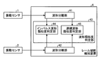
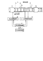
- FIG. 2 is a diagram illustrating a configuration of the rail breakage detection device 4 and the vibration sensors 1 and 2 according to the first embodiment.
- the rail breakage detection device 4 shown in FIG. 2 includes waveform separation units 41 and 42 and a waveform similarity determination unit 43.
- the waveform similarity determination unit 43 includes an impulse waveform similarity determination unit 44 and a continuous waveform similarity determination unit 45.
- the waveform separation unit 41 which is the first waveform separation unit, separates the output waveform of the vibration sensor 1 into an impulse waveform and a continuous waveform and outputs them.
- the impulse waveform that is the forced vibration component is referred to as a first impulse waveform for convenience, and the continuous waveform that is the free vibration component is referred to as a first continuous waveform for convenience.
- a waveform separation unit 42 as a second waveform separation unit separates the output waveform of the vibration sensor 2 into an impulse waveform and a continuous waveform and outputs the separated waveform.
- This impulse waveform is referred to as a second impulse waveform for convenience, and this continuous waveform is referred to as a second continuous waveform for convenience.
- examples of the method for performing waveform separation include waveform analysis, time-frequency analysis, Fourier analysis, wavelet analysis, and sparse analysis.
- the waveform similarity determination unit 43 uses the impulse waveform similarity determination unit 44 or the continuous waveform similarity determination unit 45 to compare the output waveform from the waveform separation unit 41 with the output waveform from the waveform separation unit 42 and to make similarity The degree of the degree is determined, and the rail breakage is detected from the degree of similarity.
- the waveform similarity determination unit 43 compares the impulse waveforms using the impulse waveform similarity determination unit 44, and when the train 3 moves away from the vibration sensors 1 and 2.
- the continuous waveform similarity determination unit 45 is used to compare continuous waveforms. When the train 3 approaches the vibration sensors 1 and 2, the impulse waveform component is large, so the impulse waveform is used. When the train 3 moves away from the vibration sensors 1 and 2, the impulse waveform component is attenuated and the continuous waveform component is used. The similarity is determined.
- the impulse waveform similarity determination unit 44 compares the first impulse waveform from the waveform separation unit 41 with the second impulse waveform from the waveform separation unit 42 and determines the similarity of the impulse waveform.
- the continuous waveform similarity determination unit 45 compares the first continuous waveform from the waveform separation unit 41 and the second continuous waveform from the waveform separation unit 42 to determine the similarity of the continuous waveforms.
- a method of comparing RMS (Root Mean Square) values can be exemplified.
- RMS Root Mean Square
- the strongest value of the impulse vibration may be compared, or the cross-correlation values of the time series data may be compared.
- FIG. 3 is a flowchart showing the operation of the rail breakage detection device 4 in the first embodiment.
- the waveform separation units 41 and 42 separate the waveforms from the two vibration sensors 1 and 2 into an impulse waveform that is a forced vibration component and a continuous waveform that is a free vibration component, respectively (S11).
- the impulse waveform similarity determination unit 44 determines whether or not the two impulse waveforms of the separated waveforms are similar (S12).
- the continuous waveform similarity determination unit 45 determines whether the two continuous waveforms of the separated waveforms are similar (S13).
- the waveform similarity determination unit 43 determines that there is no rail fracture (S14), and ends the process.
- the waveform similarity determination unit 43 determines that there is a rail break (S15), and performs processing. finish.
- the waveform similarity determination unit 43 shown in FIG. 2 includes both the impulse waveform similarity determination unit 44 and the continuous waveform similarity determination unit 45, but the present invention is not limited to this, and the waveform similarity The determination unit 43 only needs to include at least one of the impulse waveform similarity determination unit 44 and the continuous waveform similarity determination unit 45.
- the waveform similarity determination unit 43 includes the continuous waveform similarity determination unit 45 without including the impulse waveform similarity determination unit 44, the waveform similarity determination is performed when the train 3 moves away from the vibration sensors 1 and 2. Just do it.
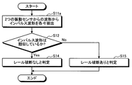
- FIG. 4 is a flowchart illustrating the operation of the rail breakage detection device 4 when the waveform similarity determination unit 43 does not include the continuous waveform similarity determination unit 45 in the first embodiment.
- the waveform separators 41 and 42 respectively extract impulse waveforms that are forced vibration components from the waveforms from the two vibration sensors (S11a).
- the impulse waveform similarity determination unit 44 determines whether or not the extracted impulse waveforms are similar (S12). When the impulse waveforms are similar (S12: Yes), the waveform similarity determination unit 43 determines that there is no rail break (S14) and ends the process.
- the impulse waveforms are not similar (S12: No)
- the waveform similarity determination unit 43 determines that there is a rail break (S15) and ends the process.
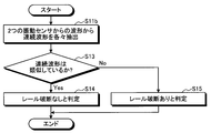
- FIG. 5 is a flowchart showing the operation of the rail breakage detection device 4 when the waveform similarity determination unit 43 does not include the impulse waveform similarity determination unit 44 in the first embodiment.
- the processing is started, and the waveform separators 41 and 42 respectively extract continuous waveforms as free vibration components from the waveforms from the two vibration sensors (S11b).
- the continuous waveform similarity determination unit 45 determines whether or not the extracted continuous waveforms are similar (S13). When the continuous waveforms are similar (S13: Yes), the waveform similar (S13: Yes), the waveform similarity determination unit 43 determines that there is no rail fracture (S14), and ends the process. If the continuous waveforms are not similar (S13: No), the waveform similarity determination unit 43 determines that there is a rail break (S15), and ends the process.
- the detection result of the presence or absence of the rail breakage is output to, for example, a route map, a display device, or a signal
- the user can know the presence or absence of the rail breakage. is there.
- the notification information to the user by a route map, a display device, a signal, or the like may be train travel availability information instead of the presence or absence of a rail break.
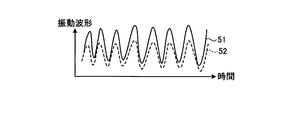
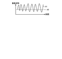
- FIG. 6 is a diagram showing a vibration waveform when the two rails are not broken in the first embodiment.
- FIG. 7 is a diagram illustrating a vibration waveform when one of the two rails is broken in the first embodiment.
- the output waveform 51 of the vibration sensor 1 and the output waveform 52 of the vibration sensor 2 have similar waveform shapes.
- the output waveform 61 of the vibration sensor 1 and the output waveform 62 of the vibration sensor 2 have dissimilar waveform shapes.
- each rail installation environment is determined. Since the difference in the state of the two rails is detected without setting the threshold values for determination one by one, the breakage of the rails can be detected regardless of the rail installation environment. Further, the detection accuracy can be improved by separating the output waveform of the vibration sensor into an impulse waveform and a continuous waveform.
- the rail breakage detection device 4 includes at least a processor, a memory, and an input unit, and the operation of each device is realized by software.
- FIG. 8 is a diagram showing a general configuration of hardware for realizing the rail breakage detection device 4 according to the present embodiment.
- the apparatus shown in FIG. 8 includes a processor 46, a memory 47, and an input unit 48.
- the processor 46 performs calculation and control by software using the received data.
- the memory 47 stores received data, stores data necessary for the processor 46 to perform calculation and control, and stores software for the processor 46 to perform calculation and control.
- the input unit 48 receives the output waveforms of the vibration sensors 1 and 2 as input.
- the waveform separation units 41 and 42 are realized by the processor 46, the memory 47, and the input unit 48, and the waveform similarity determination unit 43 is realized by the processor 46 and the memory 47.
- a plurality of processors 46 and memories 47 may be provided.
- Embodiment 2 the mode in which the two vibration sensors are mounted on different rails has been described.
- the present invention is not limited to this.
- two vibration sensors may be mounted on the same rail.
- this Embodiment about the point already demonstrated in Embodiment 1, the description which overlaps Embodiment 1 and abbreviate
- FIG. 9 is a diagram showing the rail breakage detection device 4 and the peripheral configuration according to the second embodiment of the present invention.
- FIG. 9 shows a vibration sensor 1 that is a first vibration sensor mounted on one of the two rails, and a second vibration sensor mounted on the same rail as the rail on which the vibration sensor 1 is mounted.
- a vibration sensor 2a, a train 3 traveling on two rails, and a rail breakage detection device 4 are shown.
- the vibration sensors 1 and 2a measure rail vibration.
- the train 3 travels on two rails in a direction approaching the vibration sensors 1 and 2a.
- the rails that can be detected by the vibration sensors 1 and 2a are rails on which the vibration sensors 1 and 2a are mounted.
- the vibration sensor is mounted on the rail on which the vibration sensors 1 and 2a are not mounted in the same manner as the vibration sensors 1 and 2a.
- the output waveform 51 of the vibration sensor 1 and the vibration The output waveform 52 of the sensor 2a has a similar waveform shape, and when the rail to which the vibration sensor 2a is attached is broken, the output waveform of the vibration sensor 1 and the output waveform of the vibration sensor 2a are not similar. It becomes a shape.
- the rail has a break, the propagation time of the propagating wave changes. Also, by performing within the propagation time width set in advance when calculating the similarity of the waveform, the vibration sensor 1 The output waveform and the output waveform of the vibration sensor 2a have a dissimilar waveform shape.
- one of the two vibration sensors 1 and 2a has a waveform that is attenuated by the other waveform.
- the deterioration here refers to a state in which no breakage is observed in the appearance of the rail, but an abnormality has occurred in the rail.
- a threshold for judgment must be set for each rail installation environment.
- rail breakage is detected from the similarity of vibration of rails at two or more different locations, and therefore affected by the rail material, the rail laying method, and the ground on which the rails are installed. Therefore, it is not necessary to set a threshold value for each installation environment for detecting rail breakage.
- the technology that detects the breakage of the rail by referring to the current value cannot detect the case where the rail is partially broken.
- partial rail breakage can be detected.
- the vibration waveform when there is a rail break shown in FIG. 7 is dissimilar to the vibration waveform when there is no rail break shown in FIG. 6, but when the rail break is partial, it is shown in FIG. A vibration waveform similar to the vibration waveform when there is no rail breakage is obtained with a low RMS value.
- vibration information measured by a plurality of vibration sensors is compared, vibration generated due to crossing of the vehicle, etc. is canceled out by comparison. Therefore, no erroneous detection occurs.
- this invention is not limited to this, The vibration sensor should just be provided with two or more.
- Embodiment 1, 2 it is preferable to apply Embodiment 1, 2 to the area containing the curve part on a route. That is, it is preferable that any one of the detection sections of the vibration sensor includes a curved portion on the route. This is because the rail breakage is likely to occur in the curved portion on the route due to friction with the wheel. It is particularly preferable to apply to a portion where the radius of curvature of the curved portion on the route is small.
- Embodiments 1 and 2 are also preferably applied to a section including a weld on a route. That is, it is preferable that any one of the detection sections of the vibration sensor includes a weld on the route. This is because rail breakage tends to occur at the welded portion on the route.
- Embodiment 3 FIG.
- the present invention is not limited to the embodiments described in Embodiments 1 and 2, and can also be applied to a radio train control system called CBTC (Communications Based Train Control).
- CBTC Common Train Control
- an application example to CBTC will be described.
- omits is abbreviate
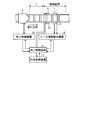
- FIG. 10 is a first diagram showing the rail breakage detection device 4 and the peripheral configuration according to the third embodiment of the present invention.
- the vibration sensor 1 which is the first vibration sensor mounted on one of the two rails and the other vibration sensor 1 of the two rails are mounted at positions facing each other.
- a vibration sensor 2 that is a second vibration sensor, a train 3 that travels on two rails, and a rail breakage detection device 4 are shown.
- the vibration sensors 1 and 2 measure rail vibration.
- the train 3 travels on two rails in a direction approaching the vibration sensors 1 and 2.
- the same detection section is set for the vibration sensors 1 and 2 on the rails to which the vibration sensors 1 and 2 are attached.
- the distance from the end of the detection section to the vibration sensors 1 and 2 is a distance at which the vibration sensors 1 and 2 can detect the rail breakage.
- a plurality of vibration sensors are provided on each rail on which the vibration sensors 1 and 2 are mounted so that the rail breakage in the adjacent section can be detected, and the adjacent sections are detected.
- the detection sections of the vibration sensor may overlap. If a part of the detection section of the vibration sensor that detects the sections adjacent to each other overlaps, it is possible to detect the rail breakage without generating a section that cannot be detected on the rail.
- the vibration sensors 1 and 2 are preferably arranged at the center of the detection section, but the place where the vibration sensors 1 and 2 are arranged is not limited as long as they are within the detection section.
- the terrestrial wireless device 6 acquires position information and speed information of the train 3 by communicating with an on-vehicle wireless device (not shown) mounted on the train 3 and transmits it to the ground control device 5.
- the rail break detection device 4 transmits the rail break detection result to the ground control device 5.
- the central control device 7 is connected to the ground control device 5.
- the central control device 7 receives the position information, speed information, and rail breakage detection result of the train 3 from the ground control device 5 and manages the operation of the train 3.
- the rail breakage detection result indicates that there is a rail breakage
- a command for stopping the train 3 is sent to the train 3 via the ground control device 5 and the ground radio device 6 and the train 3 is stopped.
- the rail breakage detection device 4 is at a timing at which the train 3 travels a point more than the braking distance L of the train 3 from the end of the direction in which the train 3 travels in the detection section of the vibration sensors 1 and 2.
- the rail breakage in the detection section of the vibration sensors 1 and 2 is detected, and the detection result is transmitted to the ground control device 5.
- This braking distance L can be calculated from the speed information of the train 3 and the rolling friction coefficient.
- the train 3 can be stopped by detecting the rail break before the train 3 passes the rail break portion.
- the rail breakage detection device 4 can calculate the braking distance L of the train 3. The calculation of the braking distance L may be performed by the ground control device 5 or the central control device 7.
- FIG. 11 is a second diagram showing the rail breakage detection device 4 and the peripheral configuration according to the third embodiment of the present invention.
- the vibration sensor 1 that is the first vibration sensor mounted on one of the two rails and the first rail mounted on the same rail as the rail on which the vibration sensor 1 is mounted.
- a vibration sensor 2a which is a vibration sensor 2, a train 3 traveling on two rails, and a rail breakage detection device 4 are shown.
- the vibration sensors 1 and 2a measure rail vibration.
- the train 3 travels on two rails in a direction approaching the vibration sensors 1 and 2a.
- the area between the vibration sensor 1 and the vibration sensor 2a is set as a detection section. That is, the installation position of the vibration sensor 1 and the vibration sensor 2a is the end of the detection section, and the distance between the vibration sensor 1 and the vibration sensor 2a is a distance at which the vibration sensors 1 and 2a can detect rail breakage.
- a vibration sensor is similarly provided on the rail where the vibration sensors 1 and 2a are not mounted.
- another vibration sensor is provided on the near side of the vibration sensor 1, and the detection sections of the vibration sensors that detect the sections adjacent to each other are arranged continuously on the rail as in FIG. Rail breakage can be detected without producing an undetectable section.
- the terrestrial radio device 6 acquires position information and speed information of the train 3 by communicating with an on-vehicle radio device (not shown) mounted on the train 3 as in FIG. 10, and transmits it to the ground control device 5.
- the rail break detection device 4 transmits the rail break detection result to the ground control device 5.
- the central control device 7 is connected to the ground control device 5.
- the central control device 7 receives the position information, speed information, and rail breakage detection result of the train 3 from the ground control device 5 and manages the operation of the train 3.
- the rail breakage detection result indicates that there is a rail breakage
- a command for stopping the train 3 is sent to the train 3 via the ground control device 5 and the ground radio device 6 and the train 3 is stopped.
- the rail breakage detection device 4 is a rail in a detection section formed by the vibration sensor 1 and the vibration sensor 2a at a timing when the train 3 travels a point before the braking distance L of the train 3 from the vibration sensor 2a.
- the fracture is detected and the detection result is transmitted to the ground control device 5.
- the central control device 7 performs control to stop the train 3 via the ground control device 5 and the ground radio device 6, so that the train 3 has the vibration sensor 1 and the vibration sensor. It is possible to stop the train 3 before entering the detection zone formed by 2a. Therefore, according to the configuration of FIG. 11, the train 3 can be stopped by detecting the rail break before the train 3 passes the rail break portion.
- the rail breakage detection device 4 can calculate the braking distance L of the train 3.
- the calculation of the braking distance L may be performed by the ground control device 5 or the central control device 7.
- Embodiment 4 When vibration generated by train travel is used as an excitation source for rail vibration, or when vibration due to train travel is small, such as when the train speed is low, rail breakage may not be detected. Therefore, in the present invention, a vibration device may be provided adjacent to the vibration sensor.
- a vibration exciter is provided adjacent to the vibration sensor in the configuration of the third embodiment.
- Embodiment 1 to 3 about the point already demonstrated in Embodiment 1-3, Embodiment 1 to 3 is used and the overlapping description is abbreviate
- the configuration in which the vibration device is provided adjacent to the vibration sensor in the configuration of the third embodiment will be described, but the configurations of the first and second embodiments and the present embodiment May be combined.
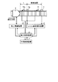
- FIG. 12 is a first diagram illustrating the rail breakage detection device 4 and the peripheral configuration according to the fourth embodiment of the present invention.
- the vibration sensor 1 which is the first vibration sensor mounted on one of the two rails, and the position opposite to the other vibration sensor 1 of the two rails are mounted.
- a vibration sensor 2 that is a second vibration sensor, a train 3 that travels on two rails, and a rail breakage detection device 4 are shown.
- the vibration sensors 1 and 2 measure rail vibration.
- the train 3 travels on two rails in a direction approaching the vibration sensors 1 and 2.
- a vibration device 71 is provided on the front side in the traveling direction of the train 3 of the vibration sensor 1, and a vibration device 72 is provided on the front side of the vibration sensor 2 in the traveling direction of the train 3.
- the vibration devices 71 and 72 vibrate the rails on which the train 3 is installed at a timing at which the position of the train 3 is a point before the braking distance L from the end of the detection section.
- the rail breakage detection device 4 detects rail breakage using vibrations generated by the vibration generators 71 and 72.
- Exciters 71 and 72 only need to be able to apply vibration to the rail. For example, a configuration in which a piston strikes the rail using electromagnetic force can be used.
- FIG. 13 is a second diagram showing the rail breakage detection device 4 and the peripheral configuration according to the fourth embodiment of the present invention.
- the vibration sensor 1 which is the first vibration sensor mounted on one of the two rails, and the first rail mounted on the same rail as the rail on which the vibration sensor 1 is mounted.
- a vibration sensor 2a which is a vibration sensor 2, a train 3 traveling on two rails, and a rail breakage detection device 4 are shown.
- the vibration sensors 1 and 2a measure rail vibration.
- the train 3 travels on two rails in a direction approaching the vibration sensors 1 and 2a.
- a vibration device 71 is provided on the front side in the traveling direction of the train 3 of the vibration sensor 1, and a vibration device 72 a is provided on the front side of the vibration sensor 2 a in the traveling direction of the train 3.
- the vibration devices 71 and 72 a are timings at which the position of the train 3 is a point before the braking distance L from the end of the detection section by a command from the central control device 7 via the ground control device 5.
- the vibration is applied to each installed rail.
- the rail breakage detection device 4 detects rail breakage using vibrations generated by the vibration generators 71 and 72a.
- the vibration devices 71, 72, 72a perform vibration according to a command from the central control device 7, but the present invention is not limited to this. You may output the command which vibrates to the vibration apparatus 71,72,72a at the timing which the rail breakage detection apparatus 4 or the ground control apparatus 5 detects a rail breakage.
- the vibration devices 71, 72, 72a are provided in front of the vibration sensors 1, 2, 2a.
- the present invention is not limited to this. It is not something. For example, when the route is a single line, the traveling direction of the train is switched, so that a vibration device may be provided on both sides of the vibration sensor.
- the rail breaks by using the vibration by the vibration generator. Before passing through the location, the train can be stopped by detecting a rail break.
- Embodiment 5 FIG.
- the rail breakage is detected using the vibration generated by the train 3, but the present invention is not limited to this.
- the rail breaks using both the vibration generated by the train 3 existing on the front side of the vibration sensor with respect to the train traveling direction and the vibration generated by the train 3a existing on the traveling direction side beyond the vibration sensor. Can also be detected.
- Embodiment 1 to 4 is used and the overlapping description is abbreviate
- the train 3 in the configuration of the third embodiment, is present on the front side in the traveling direction with respect to the train traveling direction with respect to the traveling direction of the train, and exceeds the vibration sensor in the configuration of the third embodiment.
- the form in which the train 3a exists on the traveling direction side will be described.
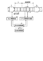
- FIG. 14 is a first diagram illustrating the rail breakage detection device 4 and the peripheral configuration according to the fifth embodiment of the present invention.
- the vibration sensor 1 which is the first vibration sensor mounted on one of the two rails and the other vibration sensor 1 of the two rails are mounted at positions facing each other.
- a train 3a that travels on two rails on the traveling direction side beyond and a rail breakage detection device 4 are shown.
- the vibration sensors 1 and 2 measure rail vibration.
- the train 3 travels on two rails in a direction approaching the vibration sensors 1 and 2
- the train 3 a travels on two rails in a direction approaching the vibration sensors 1 and 2.
- the vibration waveform generated by the train 3 is a vibration generated when approaching the vibration sensors 1 and 2, an impulse waveform is used.
- the vibration waveform generated by the train 3a is a vibration generated when moving away from the vibration sensors 1 and 2, a continuous waveform is used.
- the rail breakage detection device 4 determines the similarity between the two impulse waveforms separated by the waveform separation units 41 and 42 by the impulse waveform similarity judgment unit 44 and the two separated by the waveform separation units 41 and 42.
- the continuous waveform similarity determination unit 45 determines the similarity of the continuous waveforms.
- the method for determining the similarity of waveforms has been described in the first embodiment, and thus the description thereof is omitted.
- FIG. 15 is a second diagram showing the rail breakage detection device 4 and the peripheral configuration according to the fifth embodiment of the present invention.
- the vibration sensor 1 which is the first vibration sensor mounted on one of the two rails, and the first rail mounted on the same rail as the rail on which the vibration sensor 1 is mounted.
- the train 3 traveling on the two rails closer to the traveling direction than the vibration sensors 1 and 2a, and the vibration sensors 1 and 2a.
- a train 3a traveling on two rails on the traveling direction side and a rail breakage detection device 4 are shown.
- the vibration sensors 1 and 2a measure rail vibration.
- the train 3 travels on two rails in a direction approaching the vibration sensors 1 and 2a, and the train 3a travels on two rails in a direction away from the vibration sensors 1 and 2a.
- the determination is performed in the same manner as in FIG. 14. If the two impulse waveforms or the two continuous waveforms are dissimilar as a result of this determination, a rail fracture occurs between the vibration sensor 1 and the vibration sensor 2 a. Is determined. In this manner, rail breakage can be detected using vibration waveforms generated by a plurality of knitting.
- rail breakage can be detected using vibration waveforms generated by a plurality of knitting.
- Embodiment 6 FIG.
- the form in which the rail breakage is detected using the vibration generated by exciting the rail with the vibration apparatus has been described, but in this embodiment, the vibration by the vibration apparatus is performed a plurality of times. To calculate an average of a plurality of vibration waveforms generated by a plurality of vibrations.
- the last vibration of a plurality of vibrations is performed at a timing when the position of the train 3 is a point before the braking distance L from the end of the detection section.
- the configuration described in the above embodiment shows an example of the contents of the present invention, and can be combined with another known technique, and can be combined with other configurations without departing from the gist of the present invention. It is also possible to omit or change the part.
Landscapes
- Engineering & Computer Science (AREA)
- Physics & Mathematics (AREA)
- General Physics & Mathematics (AREA)
- Mechanical Engineering (AREA)
- Aviation & Aerospace Engineering (AREA)
- Health & Medical Sciences (AREA)
- Biomedical Technology (AREA)
- General Health & Medical Sciences (AREA)
- Train Traffic Observation, Control, And Security (AREA)
- Measurement Of Mechanical Vibrations Or Ultrasonic Waves (AREA)
- Testing Of Devices, Machine Parts, Or Other Structures Thereof (AREA)
Abstract
Priority Applications (3)
| Application Number | Priority Date | Filing Date | Title |
|---|---|---|---|
| EP17779146.4A EP3441280B1 (fr) | 2016-04-04 | 2017-04-04 | Dispositif de détection de rupture de rail |
| JP2018510619A JP6490302B2 (ja) | 2016-04-04 | 2017-04-04 | レール破断検知装置 |
| US16/079,696 US11572088B2 (en) | 2016-04-04 | 2017-04-04 | Rail break detection device |
Applications Claiming Priority (2)
| Application Number | Priority Date | Filing Date | Title |
|---|---|---|---|
| PCT/JP2016/061033 WO2017175276A1 (fr) | 2016-04-04 | 2016-04-04 | Dispositif de détection de rupture de rail |
| JPPCT/JP2016/061033 | 2016-04-04 |
Publications (1)
| Publication Number | Publication Date |
|---|---|
| WO2017175768A1 true WO2017175768A1 (fr) | 2017-10-12 |
Family
ID=60000982
Family Applications (2)
| Application Number | Title | Priority Date | Filing Date |
|---|---|---|---|
| PCT/JP2016/061033 Ceased WO2017175276A1 (fr) | 2016-04-04 | 2016-04-04 | Dispositif de détection de rupture de rail |
| PCT/JP2017/014136 Ceased WO2017175768A1 (fr) | 2016-04-04 | 2017-04-04 | Dispositif de détection de rupture de rail |
Family Applications Before (1)
| Application Number | Title | Priority Date | Filing Date |
|---|---|---|---|
| PCT/JP2016/061033 Ceased WO2017175276A1 (fr) | 2016-04-04 | 2016-04-04 | Dispositif de détection de rupture de rail |
Country Status (4)
| Country | Link |
|---|---|
| US (1) | US11572088B2 (fr) |
| EP (1) | EP3441280B1 (fr) |
| JP (1) | JP6490302B2 (fr) |
| WO (2) | WO2017175276A1 (fr) |
Families Citing this family (9)
| Publication number | Priority date | Publication date | Assignee | Title |
|---|---|---|---|---|
| WO2017175276A1 (fr) * | 2016-04-04 | 2017-10-12 | 三菱電機株式会社 | Dispositif de détection de rupture de rail |
| US11433929B2 (en) * | 2017-04-04 | 2022-09-06 | Loram Technologies, Inc. | Railroad track guidance systems and methods |
| BR102017026315B1 (pt) * | 2017-12-06 | 2023-05-16 | Rumo Logística Operadora Multimodal S.A | Método para detecção de quebra de trilho ferroviário, sistema de detecção de quebra de trilho ferroviário e dispositivo detector de quebra de trilho ferroviário |
| FR3105148B1 (fr) * | 2019-12-23 | 2023-10-06 | Commissariat Energie Atomique | Systeme et procede pour la detection d’un defaut dans un rail d’une voie ferree |
| SE545220C2 (sv) * | 2020-06-03 | 2023-05-30 | Luleaa Tekniska Univ Avd Foer Drift Och Underhaallsteknik | Metod för att i omläggningsanordning mäta skador på spårväxlar och tåghjul |
| FR3114206B1 (fr) * | 2020-09-11 | 2023-01-06 | Commissariat Energie Atomique | Système et Procédé pour la détection de défauts dans des guides d’ondes allongés. |
| CN112945372A (zh) * | 2021-01-26 | 2021-06-11 | 深圳中慧轨道智能科技有限公司 | 一种滑床板断裂监测装置 |
| KR102671392B1 (ko) * | 2023-04-28 | 2024-05-31 | 한국철도기술연구원 | 복합 방식 레일절손 판단시스템 및 이를 이용한 레일절손 판단방법 |
| CN117184175A (zh) * | 2023-08-22 | 2023-12-08 | 北京交通大学 | 基于列车自激励与无线物联技术的断轨检测方法及系统 |
Citations (4)
| Publication number | Priority date | Publication date | Assignee | Title |
|---|---|---|---|---|
| JPH07333054A (ja) * | 1994-06-06 | 1995-12-22 | West Japan Railway Co | レールのき裂検知装置 |
| JPH11118770A (ja) * | 1997-10-20 | 1999-04-30 | Tokimec Inc | 超音波探傷方法及び装置 |
| JP2008151560A (ja) * | 2006-12-15 | 2008-07-03 | Univ Nagoya | 振動特性推定方法及び振動特性推定装置 |
| US20150068296A1 (en) * | 2012-04-06 | 2015-03-12 | The Regents Of The University Of California | Air-Coupled Ultrasonic Inspection Of Rails |
Family Cites Families (17)
| Publication number | Priority date | Publication date | Assignee | Title |
|---|---|---|---|---|
| DE4116650A1 (de) | 1991-05-22 | 1992-11-26 | Gerd R Dipl Ing Wetzler | Verfahren zur erkennung von schienenunterbrechungen bei endlos verschweissten eisenbahnschienen |
| US5743495A (en) * | 1997-02-12 | 1998-04-28 | General Electric Company | System for detecting broken rails and flat wheels in the presence of trains |
| GB0104688D0 (en) * | 2001-02-26 | 2001-04-11 | Roke Manor Research | Active rail health monitoring system |
| US6911914B2 (en) * | 2002-03-29 | 2005-06-28 | General Electric Company | Method and apparatus for detecting hot rail car surfaces |
| US6951132B2 (en) * | 2003-06-27 | 2005-10-04 | General Electric Company | Rail and train monitoring system and method |
| WO2006030786A1 (fr) * | 2004-09-13 | 2006-03-23 | Nsk Ltd. | Dispositif de diagnostic d’anomalie et procede de diagnostic d’anomalie |
| US20060076461A1 (en) * | 2004-10-12 | 2006-04-13 | General Electric Company | System and method for self powered wayside railway signaling and sensing |
| JP4569437B2 (ja) * | 2005-08-31 | 2010-10-27 | 日本精工株式会社 | 異常診断装置 |
| JP2010096541A (ja) * | 2008-10-14 | 2010-04-30 | Thk Co Ltd | 損傷検査装置、方法 |
| US20120279308A1 (en) * | 2011-05-04 | 2012-11-08 | Fbs, Inc. | Elastic wave rail defect detection system |
| CZ23860U1 (cs) * | 2012-04-18 | 2012-05-21 | Jaluvka@Otakar | Zařízení k monitoringu, detekci a diagnostice drážních vozidel pozemních, podzemních i nadzemních drah a jejich komponentů za jízdy |
| WO2014027977A1 (fr) * | 2012-08-14 | 2014-02-20 | ENEKOM ENERJI EKOLOJI BILIŞIM VE MUHENDISLIK SANAYI TICARET LIMITED ŞlRKETI | Procédé de détection de fractures et de fissures de rail |
| JP6297280B2 (ja) | 2013-08-09 | 2018-03-20 | 日本信号株式会社 | レール破断検知装置 |
| JP6465034B2 (ja) * | 2013-12-27 | 2019-02-06 | 日本電気株式会社 | 信号解析装置、加振力測定システム、信号解析方法および信号解析プログラム |
| CN107406090B (zh) * | 2015-01-16 | 2020-11-20 | 国际电子机械公司 | 异常车辆动态检测 |
| WO2017175276A1 (fr) * | 2016-04-04 | 2017-10-12 | 三菱電機株式会社 | Dispositif de détection de rupture de rail |
| CA3200604A1 (fr) * | 2017-03-24 | 2018-09-24 | Canadian Pacific Railway Company | Entretien de roulements a rouleaux de wagon fonde sur l'etat employant les alertes predictives de bordure de voie fondees sur les mesures de detection acoustique de palier |
-
2016
- 2016-04-04 WO PCT/JP2016/061033 patent/WO2017175276A1/fr not_active Ceased
-
2017
- 2017-04-04 JP JP2018510619A patent/JP6490302B2/ja not_active Expired - Fee Related
- 2017-04-04 WO PCT/JP2017/014136 patent/WO2017175768A1/fr not_active Ceased
- 2017-04-04 EP EP17779146.4A patent/EP3441280B1/fr not_active Not-in-force
- 2017-04-04 US US16/079,696 patent/US11572088B2/en active Active
Patent Citations (4)
| Publication number | Priority date | Publication date | Assignee | Title |
|---|---|---|---|---|
| JPH07333054A (ja) * | 1994-06-06 | 1995-12-22 | West Japan Railway Co | レールのき裂検知装置 |
| JPH11118770A (ja) * | 1997-10-20 | 1999-04-30 | Tokimec Inc | 超音波探傷方法及び装置 |
| JP2008151560A (ja) * | 2006-12-15 | 2008-07-03 | Univ Nagoya | 振動特性推定方法及び振動特性推定装置 |
| US20150068296A1 (en) * | 2012-04-06 | 2015-03-12 | The Regents Of The University Of California | Air-Coupled Ultrasonic Inspection Of Rails |
Non-Patent Citations (1)
| Title |
|---|
| See also references of EP3441280A4 * |
Also Published As
| Publication number | Publication date |
|---|---|
| WO2017175276A1 (fr) | 2017-10-12 |
| US20190300032A1 (en) | 2019-10-03 |
| EP3441280B1 (fr) | 2021-12-29 |
| JPWO2017175768A1 (ja) | 2018-08-09 |
| JP6490302B2 (ja) | 2019-03-27 |
| US11572088B2 (en) | 2023-02-07 |
| EP3441280A4 (fr) | 2019-05-15 |
| EP3441280A1 (fr) | 2019-02-13 |
Similar Documents
| Publication | Publication Date | Title |
|---|---|---|
| JP6490302B2 (ja) | レール破断検知装置 | |
| KR102423390B1 (ko) | 열차 내 힘 모니터링을 위한 분산형 광섬유 감지 | |
| CN106662483B (zh) | 铁轨轮组中的异常检测 | |
| CN108474674B (zh) | 使用分布式光纤传感进行追踪 | |
| EP3792142B1 (fr) | Dispositif et methode ferroviaire faisant appel à une surveillance acoustique | |
| CN105549017B (zh) | 物体检测装置 | |
| US10451734B2 (en) | Object detecting apparatus | |
| KR101382656B1 (ko) | V2x 통신을 이용한 교차로 접근차량 경보 장치 및 방법 | |
| JP2021507223A (ja) | 電気音響トランスデューサを備えるwimセンサー | |
| WO2016042697A1 (fr) | Dispositif de détection d'obstacle | |
| WO2013125110A1 (fr) | Dispositif de détermination d'obstacle | |
| JP6327297B2 (ja) | 交通情報取得装置、交通情報取得方法、および交通情報取得プログラム | |
| JPH11342845A (ja) | 列車検知装置及び列車位置検知システム、並びに列車接近警報発生装置 | |
| JP7027810B2 (ja) | 物体検知装置 | |
| US20220032981A1 (en) | Railroad monitoring system, railroad monitoring device, railroad monitoring method, and non-transitory computer-readable medium | |
| KR101970010B1 (ko) | 복수 개 초음파 센서를 이용한 차량 검출장치 및 그 검출방법 | |
| JP6365633B2 (ja) | 車長推定装置、交通管制システム、車長推定方法、および車長推定プログラム | |
| US10515545B2 (en) | Position determining device and operating method thereof | |
| JP2017081257A (ja) | 移動体位置検出システム | |
| JP6426586B2 (ja) | 物体検知装置 | |
| KR101537335B1 (ko) | 진동 분석 장치, 및 이를 이용한 진동 패턴 인식 방법 | |
| JP2020132064A (ja) | 検知方法、警報制御方法、検知装置および警報制御装置 | |
| JP2016014537A (ja) | センサ | |
| JPH0628595A (ja) | 交通流計測方法 | |
| JP4652410B2 (ja) | 運転支援システム、運転支援装置、運転支援方法、運転支援プログラムおよび記録媒体 |
Legal Events
| Date | Code | Title | Description |
|---|---|---|---|
| ENP | Entry into the national phase |
Ref document number: 2018510619 Country of ref document: JP Kind code of ref document: A |
|
| NENP | Non-entry into the national phase |
Ref country code: DE |
|
| WWE | Wipo information: entry into national phase |
Ref document number: 2017779146 Country of ref document: EP |
|
| ENP | Entry into the national phase |
Ref document number: 2017779146 Country of ref document: EP Effective date: 20181105 |
|
| 121 | Ep: the epo has been informed by wipo that ep was designated in this application |
Ref document number: 17779146 Country of ref document: EP Kind code of ref document: A1 |