WO2017175795A1 - Dispositif de mesure de facteur de diffusion thermique, procédé de mesure de facteur de diffusion thermique et programme - Google Patents
Dispositif de mesure de facteur de diffusion thermique, procédé de mesure de facteur de diffusion thermique et programme Download PDFInfo
- Publication number
- WO2017175795A1 WO2017175795A1 PCT/JP2017/014223 JP2017014223W WO2017175795A1 WO 2017175795 A1 WO2017175795 A1 WO 2017175795A1 JP 2017014223 W JP2017014223 W JP 2017014223W WO 2017175795 A1 WO2017175795 A1 WO 2017175795A1
- Authority
- WO
- WIPO (PCT)
- Prior art keywords
- thermal diffusivity
- detection
- temperature
- measurement object
- heating
- Prior art date
- Legal status (The legal status is an assumption and is not a legal conclusion. Google has not performed a legal analysis and makes no representation as to the accuracy of the status listed.)
- Ceased
Links
Images




Classifications
-
- G—PHYSICS
- G01—MEASURING; TESTING
- G01N—INVESTIGATING OR ANALYSING MATERIALS BY DETERMINING THEIR CHEMICAL OR PHYSICAL PROPERTIES
- G01N25/00—Investigating or analyzing materials by the use of thermal means
- G01N25/18—Investigating or analyzing materials by the use of thermal means by investigating thermal conductivity
-
- G—PHYSICS
- G01—MEASURING; TESTING
- G01N—INVESTIGATING OR ANALYSING MATERIALS BY DETERMINING THEIR CHEMICAL OR PHYSICAL PROPERTIES
- G01N33/00—Investigating or analysing materials by specific methods not covered by groups G01N1/00 - G01N31/00
- G01N33/0003—Composite materials
-
- G—PHYSICS
- G01—MEASURING; TESTING
- G01N—INVESTIGATING OR ANALYSING MATERIALS BY DETERMINING THEIR CHEMICAL OR PHYSICAL PROPERTIES
- G01N33/00—Investigating or analysing materials by specific methods not covered by groups G01N1/00 - G01N31/00
Definitions
- the present invention relates to a thermal diffusivity measuring apparatus, a thermal diffusivity measuring method and a program used for measuring the thermal diffusivity of a sample.
- carbon fiber reinforced composite materials have been widely used in electronic devices and the like as materials having high thermal conductivity, anisotropy and high specific rigidity.
- a large difference occurs in thermal diffusivity due to anisotropy generated by the orientation of carbon fibers.
- Carbon fiber reinforced composite materials generally have a high thermal diffusivity in the in-plane direction because the fibers are oriented in the in-plane direction of the material. Also, due to the downsizing of electronic devices, heat-dissipating carbon fiber reinforced composite materials are used for heat dissipation of CPUs and batteries, but these heat-dissipating materials also have strong atomic bonds arranged in the in-plane direction. The thermal diffusivity in the in-plane direction is high.
- an isotropic sample having the same thermal diffusivity in both the in-plane direction and the thickness direction is targeted, and it does not take into account that it takes time for the thermal diffusion in the thickness direction. Therefore, in the conventional general thermal diffusivity measurement method, a correct value cannot be measured in the case of an anisotropic sample having a thickness of 100 ⁇ m or more.
- Non-Patent Document 1 discloses a method using the AC calorimetry method. In this thermal diffusivity measuring method, the three-dimensional theory is applied, and the thermal diffusivity in the in-plane direction and the thickness direction is analyzed simultaneously by fitting the solution of the heat conduction equation to the measurement result.
- Patent Document 1 discloses a thermal diffusivity measuring device developed by the inventors of the present application.
- the thermal diffusivity measuring device disclosed in Patent Document 1 heats the surface of a plate-like object to be measured by laser spot periodic heating, detects the temperature change of the back surface of the object to be measured by infrared thermography, and changes the temperature. And the heating cycle are calculated, and the thermal diffusivity of the measurement object is calculated based on the calculated phase delay.
- thermocouple used for this type of measurement is very thin and requires great care in handling the thermocouple itself. As a result, sample adjustment and measurement error by the operator are also large.
- thermocouple instead of a thermocouple, a configuration using a radiation thermometer using InSb or the like that can measure the sample temperature in a non-contact manner as a detection element is conceivable.
- a radiation thermometer is arranged at a distance from the sample, the measurement of the AC temperature of the sample is performed on a region having a spread due to the configuration of the optical system, resulting in a decrease in accuracy. There was a problem that.
- the thermal diffusivity measuring device described in Patent Document 1 can accurately measure the thermal diffusivity in the in-plane direction and the thermal diffusivity in the thickness direction of a carbon fiber reinforced composite material having a thickness of about 130 ⁇ m.
- measurement of a thicker measurement object has been demanded, and even the thermal diffusivity measuring device described in Patent Document 1 may be difficult to cope with.
- an object of the present invention is to provide a thermal diffusivity measuring apparatus, a thermal diffusivity measuring method, and a program that can suppress a decrease in accuracy even if temperature is detected without contact. Furthermore, another object of the present invention is to provide a thermal diffusivity with high accuracy even for a measurement object having anisotropy that has a large difference in thermal diffusivity between the in-plane direction and the thickness direction and is thick. An object of the present invention is to provide a thermal diffusivity measuring device, a thermal diffusivity measuring method, and a program that can be measured.
- the thermal diffusivity measuring device of the present invention comprises a heating means for periodically heating a heating location on the surface of a measurement object having a front surface and a back surface, and the back surface of the measurement object.
- a non-contact temperature sensor that detects the temperature of the detected portion in a non-contact manner, and calculates a phase lag of a detection temperature cycle by the non-contact temperature sensor with respect to a heating cycle by the heating means, and the measurement based on the calculated phase lag
- Thermal diffusivity calculating means for calculating the thermal diffusivity of the object, wherein the thermal diffusivity calculating means obtains the intensity of the detection sensitivity distribution at the detection location for the detection temperature of the non-contact temperature sensor, and the detection location
- the phase of the detected temperature cycle and the intensity of the obtained detection sensitivity distribution are integrated to calculate the phase lag at the detection location and calculate the heat of the measurement object. Characterized by calculating the Chiritsu.
- the thermal diffusivity measuring method of this invention measures the thermal diffusivity of the said measurement object by heating the surface of the measurement object which has a surface and a back surface, and detecting the temperature of the back surface of the said measurement object.
- the intensity of the detection sensitivity distribution at the detection location is obtained for the temperature detected in the temperature detection step, and the phase of the detection temperature cycle at the detection location and the strength of the detected detection sensitivity distribution are obtained.
- the inventors of the present application calculate the thermal diffusivity using the value obtained by integrating not only the temperature of a specific measurement point, but also the detected temperature of the surroundings, to detect the temperature of the measurement object. It has been found that the thermal diffusivity in the in-plane direction and the thickness direction can be accurately measured even for a measurement object having anisotropy that is greatly different from that in the thickness direction and having a large thickness.
- the thermal diffusivity measuring device and the measuring method of the present invention obtain the detection temperature in a range of detection sensitivity distribution centered on the detection location, and the phase of the detection temperature cycle at the detection location and the measurement temperature By integrating the detection temperature within the detection sensitivity distribution, the phase lag at the detection location is calculated, and the thermal diffusivity of the measurement object is calculated.
- the measurement object may have a plate shape, a rod shape, or another shape.
- the detected temperature in the detection sensitivity distribution is obtained from the full width at half maximum of the detected temperature at the detection location. According to the knowledge of the inventors of the present application, the thermal diffusivity in the in-plane direction and the thickness direction of the measurement object can be measured more accurately by adopting this configuration.
- the heating means is a laser irradiation unit that heats by laser irradiation
- the laser irradiation unit is a Gaussian beam whose intensity is modulated at a predetermined angular frequency. It is preferable to heat.
- the heated portion is heated with a Gaussian beam whose intensity is modulated at a predetermined angular frequency.
- the measurement object was irradiated in the case of laser irradiation. Since the intensity distribution in the in-plane direction was close to a Gaussian distribution, a Gaussian beam in which laser irradiation was intensity-modulated at a predetermined angular frequency was used. With this configuration, the thermal diffusivity in the in-plane direction and the thickness direction of the measurement object can be measured more accurately.
- the thermal diffusion measurement program of the present invention is executed by a computer, and uses the thermal diffusivity measuring device to heat the surface of the measurement object having the front surface and the back surface, and detects the temperature of the back surface of the measurement object.
- a thermal diffusion measurement program for measuring the thermal diffusivity of the measurement object by periodically heating the surface of the measurement object in a non-contact manner by a thermal diffusivity measurement device; Detect the temperature of the detection location on the back surface in a non-contact manner, obtain the intensity of the detection sensitivity distribution at the detection location for the detected temperature, and integrate the phase of the detection temperature cycle at the detection location and the intensity of the detection sensitivity distribution
- the thermal diffusivity of the measurement object is calculated by calculating the phase lag between the heating cycle and the detection temperature cycle at the detection location.
- the program makes it possible to execute the thermal diffusivity measuring apparatus and the thermal diffusivity measuring method.
- Explanatory drawing which shows the structure of the thermal diffusivity measuring apparatus of this embodiment.
- Explanatory drawing which shows the state of a heating location and a detection location when a temperature wave is produced in the heating location of a sample.
- (A) is explanatory drawing which shows the state of the temperature wave in a sample at the time of irradiating the laser beam to the heating location of a sample.
- (B) is explanatory drawing which shows the image of the phase delay of the temperature wave detected at a detection location, and a heating wave.
- Explanatory drawing which shows the phase delay of a temperature wave, and the intensity
- (A) And (B) is explanatory drawing which shows the data at the time of calculating
- the thermal diffusivity measuring apparatus 1 of this embodiment includes a laser irradiation unit 2 as a heating unit, an infrared thermography 3 as a non-contact temperature sensor, and a computer 4 as a thermal diffusivity calculating unit.
- the computer 4 stores a program for operating the thermal diffusivity measuring device 1 to execute the thermal diffusivity measuring method.
- the thermal diffusivity measuring apparatus 1 includes a holder 6 for holding a plate-like sample 5 as a measurement object, the holder 6 in the X direction and the Y direction (both in-plane directions of the sample 5), and further in the Z direction.
- An XYZ stage 7 that moves in the thickness direction of the sample 5 is provided.
- the laser irradiation unit 2 uses a semiconductor laser device in this embodiment, and is arranged so as to heat the surface of the sample 5 (the left side surface of the sample 5 in FIG. 1).
- the laser irradiation unit 2 changes the intensity by changing the current supplied to the apparatus when irradiating the laser beam.
- the heating unit includes a first mirror 8, an acoustooptic device 9, a second mirror 10, a beam expander 11, and a microscope 12.
- the first mirror 8 and the second mirror 10 reflect the laser beam emitted from the laser irradiation unit 2 and guide it to the beam expander 11.
- the acoustooptic device 9 is connected to a periodic signal generator 13 and receives a periodic signal transmitted from the periodic signal generator 13 and converts a laser beam emitted from the laser irradiation unit 2 into a periodic signal. It is.
- the frequency of the laser beam emitted from the laser irradiation unit 2 is set to 0.005 Hz to 300 Hz.
- the beam expander 11 expands the beam diameter of the laser beam guided by the second mirror 10.
- the laser beam is irradiated as a spot on the heating spot H on the surface of the sample 5 through the microscope 12 provided on the XY stage 14 (see FIG. 2).
- the laser beam applied to the heated portion H of the sample 5 is configured to be a so-called Gaussian beam.
- the Gaussian beam in the present embodiment is formed by modulating the intensity of the laser beam at a predetermined angular frequency in the laser irradiation unit 2.
- this angular frequency is 2 ⁇ f.
- the infrared thermography 3 is a device that can acquire heat generated from the surface of a measurement object in a non-contact manner as an image and measure the temperature from the image.
- the infrared thermography 3 is arranged so as to measure the temperature of the detection portion S on the back surface of the sample 5.
- the infrared thermography 3 is connected to the periodic signal generator 13 and the lock-in amplifier 15, and transmits temperature data to the computer 4 through the lock-in amplifier 15 as a periodic signal.
- the lock-in amplifier 15 is a phase of the heating cycle obtained by the infrared thermography 3 with respect to the heating cycle by the laser irradiation unit 2 from the temperature modulation signal transmitted from the infrared thermography 3 and the reference signal transmitted from the periodic signal generator 13. It is a device that detects a delay.
- the periodic signal generator 13 is a so-called function generator that can generate an AC signal having an arbitrary frequency and waveform.
- a periodic signal is transmitted to the acoustooptic device 9 and the infrared thermography 3 under the control of the computer 4.
- the LED 16 and the CCD camera 17 are configured to visually check the surface state of the sample 5 through the microscope 12.
- the XYZ stage 7 and the XY stage 14 are mounted on a rail 18 provided in the thermal diffusivity measuring apparatus 1.
- the thermal diffusivity measuring method of this embodiment is comprised from each process of a heating process, a temperature detection process, and a calculation process.
- a user who performs measurement inputs parameters necessary for measuring the thermal diffusivity into the thermal diffusivity measuring apparatus 1. For example, the frequency of the laser, the laser power, the distance between the microscope 12 and the sample 5, the interval between measurement points by the infrared thermography 3, the thickness of the sample, the external dimensions of the sample, and the like.
- the sample 5 that is a measurement object for measuring the thermal diffusivity is a graphite sheet (carbon fiber reinforced composite material) or CFRTP (carbon fiber reinforced thermoplastic resin), and has an anisotropic thermal diffusivity.
- the thermal diffusivity ax, ay in the in-plane direction (X direction and Y direction) is different from the thermal diffusivity az in the thickness direction (z direction).
- the sample 5 in this embodiment has the same thermal diffusivity in the X direction and the Y direction.
- the sample 5 is 50 mm in length (Len in FIG. 2) ⁇ 50 mm in width (Wid in FIG. 2) and has a thickness d of 400 ⁇ m.
- the size of the sample 5 can be 10 mm or more in a size that can be attached to the thermal diffusivity measuring apparatus 1.
- the sample 5 having a thickness of 0.01 mm to 2 mm can be used.
- a laser beam is irradiated from the laser irradiation unit 2, reflected by the first mirror 8, and introduced into the acoustooptic device 9.
- the laser beam is converted into a periodic heating wave by a periodic signal from the periodic signal generator 13 controlled by the computer 4.
- the laser beam that has passed through the acoustooptic device 9 is reflected by the second mirror 10, the beam diameter is enlarged by the beam expander 11, and the heated portion H on the surface of the sample 5 is irradiated from the microscope 12.
- the temperature of the detection portion S on the back surface of the sample 5 is detected by the infrared thermography 3 in a non-contact manner.
- the temperature of the detection location S of the sample 5 is acquired as an image.
- the image data since the heating location H is periodically heated by the laser beam, and the temperatures of the heating location H and the detection location S change periodically, the image data changes periodically. It becomes.
- a periodic signal is input to the infrared thermography 3 from the periodic signal generator 13 and transmitted to the computer 4 via the lock-in amplifier 15 together with the acquired image data.
- the image data acquired in the infrared thermography 3 is continuously fetched and calculated based on a frame rate at a predetermined interval, and the temperature changes every moment. Image data averaged from the amount of change is created.
- the computer 4 calculates the heating cycle of the laser beam that heated the sample 5 in the heating step and the detection temperature cycle of the image data detected by the infrared thermography 3 in the temperature detection step and passed through the lock-in amplifier 15.
- the phase delay ⁇ ′ is calculated. Further, the computer 4 obtains the thermal diffusivity of the sample 5 from the phase delay ⁇ ′.
- the laser beam L irradiated from the microscope 12 is irradiated to the heating spot H on the surface side of the sample 5.
- the laser beam L is a periodic heating wave, and as shown in FIGS. 2 and 3, the temperature wave TW propagates inside the sample 5 and spreads around.
- the temperature wave TW propagated from the heating location H is detected at the detection location S.
- the temperature wave TW generated by heating at the heating location H is detected with a phase delay.
- a signal is detected within a detection sensitivity distribution DS in the detection location S.
- FIG. 4 is a diagram schematically showing the relationship between the phase delay ⁇ of the temperature wave TW and the intensity P of the detection sensitivity distribution in the X direction.
- the temperature wave TW generated at the heating location H attenuates as it propagates through the sample 5 and is detected at the detection location S.
- the detection location S is detected.
- the temperature wave TW is detected in a certain range instead of one point.
- the range is the detection sensitivity distribution DS shown in FIG. 4, and as shown in FIG. 4, the level of the detected temperature signal has a mountain shape with the center of the detection location S as the apex.
- the center coordinates (x ′, y ′, z ′) of the heating location H are the origin, and the coordinates of the center of the detection location S are (x, y, z).
- the term “heating location H” or “detection location S” includes the case of each center.
- the sample 5 having the same thermal diffusivity is used in the X direction and the Y direction. Therefore, the thermal diffusivity ax in the X direction is the same as the thermal diffusivity ay in the Y direction.
- the temperature T at a certain time point t at which the detection point is present can be expressed by the following equation (1).
- Equation (1) is a thermal distance from the center coordinate of the heating location H to the center coordinate of the detection location S, and is represented by the following equation (2).
- k in the equation (1) is the wave number of the temperature wave having the frequency f propagating inside the sample 5, and is represented by the following equation. Further, ⁇ is an angular frequency (2 ⁇ f) at the time of heating modulation.
- phase ⁇ of the detection temperature cycle at the detection location S is expressed by the following equation (5).
- l is the distance in the in-plane direction from the center coordinates (x ′, y ′, z ′) of the heating location H, and is r in this embodiment.
- k shows a wave number in (5) Formula.
- the intensity P of the detection sensitivity distribution DS at the detection location S is expressed by the following equation (6).
- R in equation (6) is the standard deviation of the normal distribution of the detected temperature signal, and is represented by the following equation (7). Further, W in Expression (7) is obtained from the full width at half maximum of the detection sensitivity distribution DS.
- phase delay ⁇ ′ considering the detection sensitivity distribution is obtained by the following equation (8) by convolving and integrating the phase delay ⁇ and the intensity P of the detection sensitivity distribution.
- the above calculation is performed by the program stored in the computer 4 as the calculation means.
- the computer 4 performs the calculation at a plurality of measurement points, and plots the result on the graph shown in FIG. 5 (AR in FIG. 5).
- FIG. 5 AR in FIG. 5
- fitting to a graph showing the relationship between the distance r in the X direction and the measured phase delay ⁇ ′ is performed. Determine the thermal diffusivity ar in the direction.
- curves a (H) and a (L) are obtained by storing the results of measurement using a sample having a known thermal diffusivity in the thermal diffusivity measuring apparatus 1.
- a curve a (H) shows a state where the thermal diffusivity in the in-plane direction is high
- a curve a (L) shows a state where the thermal diffusivity in the in-plane direction is low.
- the arrow in the vicinity of the curve a (H) indicates a state of fitting so that the thermal diffusivity in the in-plane direction is low
- the arrow in the vicinity of the curve a (L) has a high thermal diffusivity in the in-plane direction.
- a state of fitting so as to be in a state is shown.
- the calculation for any of the above-mentioned fittings is performed by the computer 4, and the thermal diffusivity of the straight line that fits the plotted measurement result is set as the thermal diffusivity of the sample 5.
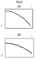
- FIG. 6A and 6 (B) are explanatory diagrams showing data when the thermal diffusivity of CFRTP is obtained by fitting in the procedure shown in FIG.
- the measurement is performed with the frequency of the laser emitted from the laser irradiation unit 2 set to 0.01 Hz.
- FIG. 6B measurement is performed with the frequency set to 0.05 Hz.
- the black dots are actual measured values, and the solid line is the fitting result.
- the thermal diffusivity measuring apparatus 1 of the present embodiment is able to normally fit the results of measuring the same sample at a plurality of frequencies. confirmed.
- the measurement method for the sample 5 having the same thermal diffusivity ax and ay in the in-plane direction has been described, but in the case of a sample having anisotropy of the thermal diffusivity in the in-plane direction, By considering this anisotropy in the above calculation formula, the same calculation as in the above embodiment can be performed.
- the thermal diffusivity ay in the Y direction can be calculated as a value obtained by multiplying ax by an anisotropic ratio.
- the graphite sheet and CFRTP were used as the sample 5, it is not restricted to this, Even if it measures thermal diffusivity about the sample which has anisotropy or does not have anisotropy Good.
- the Gaussian beam has an angular frequency of 2 ⁇ f.
- the present invention is not limited to this and may have other values.
- SYMBOLS 1 Thermal diffusivity measuring apparatus, 2 ... Laser irradiation part, 3 ... Infrared thermography (non-contact temperature sensor), 4 ... Computer, 5 ... Sample, 6 ... Holder, 8 ... 1st mirror, 7 ... XYZ stage, 9 ... Acousto-optic element, 10 ... second mirror, 11 ... beam expander, 12 ... microscope, 13 ... periodic signal generator, 14 ... XY stage, 15 ... lock-in amplifier, 16 ... LED, 17 ... CCD camera, 18 ... Rail, H ... heating location, L ... laser beam, S ... detection location, TW ... temperature wave.
Landscapes
- Chemical & Material Sciences (AREA)
- Health & Medical Sciences (AREA)
- Life Sciences & Earth Sciences (AREA)
- General Health & Medical Sciences (AREA)
- Analytical Chemistry (AREA)
- Biochemistry (AREA)
- Physics & Mathematics (AREA)
- General Physics & Mathematics (AREA)
- Immunology (AREA)
- Pathology (AREA)
- Engineering & Computer Science (AREA)
- Food Science & Technology (AREA)
- Medicinal Chemistry (AREA)
- Investigating Or Analyzing Materials Using Thermal Means (AREA)
- Radiation Pyrometers (AREA)
Abstract
[Problème] Fournir un dispositif de mesure de facteur de diffusion thermique, un procédé de mesure de facteur de diffusion thermique et un programme capables de mesurer une diffusion thermique avec une précision élevée, même lorsqu'un objet à mesurer a une anisotropie dans laquelle des facteurs de diffusion thermique diffèrent considérablement entre la direction dans le plan et la direction de l'épaisseur, et une épaisseur élevée. [Solution] La présente invention concerne un procédé de mesure de facteur de diffusion thermique, dans lequel un emplacement de chauffage H sur un échantillon tabulaire est amené à générer périodiquement des ondes thermiques variables et les ondes thermiques à un emplacement de détection S sur l'échantillon sont détectées par un capteur de température sans contact. En outre, le retard de phase des ondes thermiques à l'emplacement de détection S est détecté en tenant compte d'une distribution de sensibilité de détection DS du capteur de température sans contact et le facteur de diffusion thermique dans la direction dans le plan de l'échantillon est mesuré au moyen du retard de phase.
Priority Applications (3)
| Application Number | Priority Date | Filing Date | Title |
|---|---|---|---|
| CN201780021953.8A CN109416332B (zh) | 2016-04-06 | 2017-04-05 | 热扩散率测定装置、热扩散率测定方法以及程序 |
| US16/091,805 US11035809B2 (en) | 2016-04-06 | 2017-04-05 | Thermal diffusion factor measurement device, thermal diffusion factor measurement method and program |
| JP2018510636A JP6601748B2 (ja) | 2016-04-06 | 2017-04-05 | 熱拡散率測定装置、熱拡散率測定方法およびプログラム |
Applications Claiming Priority (2)
| Application Number | Priority Date | Filing Date | Title |
|---|---|---|---|
| JP2016076616 | 2016-04-06 | ||
| JP2016-076616 | 2016-04-06 |
Publications (1)
| Publication Number | Publication Date |
|---|---|
| WO2017175795A1 true WO2017175795A1 (fr) | 2017-10-12 |
Family
ID=60001249
Family Applications (1)
| Application Number | Title | Priority Date | Filing Date |
|---|---|---|---|
| PCT/JP2017/014223 Ceased WO2017175795A1 (fr) | 2016-04-06 | 2017-04-05 | Dispositif de mesure de facteur de diffusion thermique, procédé de mesure de facteur de diffusion thermique et programme |
Country Status (4)
| Country | Link |
|---|---|
| US (1) | US11035809B2 (fr) |
| JP (1) | JP6601748B2 (fr) |
| CN (1) | CN109416332B (fr) |
| WO (1) | WO2017175795A1 (fr) |
Families Citing this family (2)
| Publication number | Priority date | Publication date | Assignee | Title |
|---|---|---|---|---|
| DE102021127596A1 (de) | 2021-10-22 | 2023-04-27 | Linseis Messgeräte Gesellschaft mit beschränkter Haftung | Temperaturleitfähigkeitsmessgerät |
| US11796496B1 (en) * | 2022-08-29 | 2023-10-24 | Arrigo Enterprises, Llc | Instrument and method for measuring thermal diffusivity of materials |
Citations (2)
| Publication number | Priority date | Publication date | Assignee | Title |
|---|---|---|---|---|
| JP2014160038A (ja) * | 2013-02-20 | 2014-09-04 | Ibaraki Univ | 熱拡散率測定装置 |
| JP2015108546A (ja) * | 2013-12-04 | 2015-06-11 | 国立大学法人名古屋大学 | 熱拡散率測定装置 |
Family Cites Families (8)
| Publication number | Priority date | Publication date | Assignee | Title |
|---|---|---|---|---|
| JP2688012B2 (ja) * | 1995-05-12 | 1997-12-08 | 工業技術院長 | 熱拡散率測定方法 |
| US6595685B2 (en) * | 1998-10-13 | 2003-07-22 | National Research Laboratory Of Metrology | Method and apparatus for measuring thermophysical properties |
| EP1450155A1 (fr) * | 2001-11-19 | 2004-08-25 | The Circle for the Promotion of Science and Engineering | Methode et systeme d'analyse thermique |
| US7409313B2 (en) * | 2005-12-16 | 2008-08-05 | General Electric Company | Method and apparatus for nondestructive evaluation of insulative coating |
| CN101929968B (zh) * | 2009-10-30 | 2012-07-18 | 中国计量科学研究院 | 热扩散率测量装置 |
| CN101706463B (zh) * | 2009-11-25 | 2011-11-23 | 东华大学 | 一种多相多孔材料热传导性能的非稳态测量装置及方法 |
| US9291510B2 (en) * | 2012-06-19 | 2016-03-22 | Levex Corporation | Measuring apparatus |
| EP2840385A1 (fr) * | 2013-08-23 | 2015-02-25 | DCG Systems, Inc. | Procédé et système de thermographie lock-in permettant de déterminer les paramètres de couche de matériau d'un échantillon |
-
2017
- 2017-04-05 CN CN201780021953.8A patent/CN109416332B/zh not_active Expired - Fee Related
- 2017-04-05 US US16/091,805 patent/US11035809B2/en active Active
- 2017-04-05 WO PCT/JP2017/014223 patent/WO2017175795A1/fr not_active Ceased
- 2017-04-05 JP JP2018510636A patent/JP6601748B2/ja active Active
Patent Citations (2)
| Publication number | Priority date | Publication date | Assignee | Title |
|---|---|---|---|---|
| JP2014160038A (ja) * | 2013-02-20 | 2014-09-04 | Ibaraki Univ | 熱拡散率測定装置 |
| JP2015108546A (ja) * | 2013-12-04 | 2015-06-11 | 国立大学法人名古屋大学 | 熱拡散率測定装置 |
Non-Patent Citations (1)
| Title |
|---|
| SHINOHARA ET AL, THE JAPAN INSTITUTE OF METALS 2016 NEN (DAI 158 KAI) SHUNKI KOEN TAIKAI KOEN GAIYOSHU, 9 March 2016 (2016-03-09), pages 133 * |
Also Published As
| Publication number | Publication date |
|---|---|
| CN109416332B (zh) | 2021-07-06 |
| JPWO2017175795A1 (ja) | 2019-02-14 |
| JP6601748B2 (ja) | 2019-11-06 |
| US11035809B2 (en) | 2021-06-15 |
| US20190162683A1 (en) | 2019-05-30 |
| CN109416332A (zh) | 2019-03-01 |
Similar Documents
| Publication | Publication Date | Title |
|---|---|---|
| Sun | Analysis of pulsed thermography methods for defect depth prediction | |
| JP6545765B2 (ja) | 熱拡散率測定装置 | |
| JP2015108546A (ja) | 熱拡散率測定装置 | |
| JP5058180B2 (ja) | 基板上に構成された薄層材料を、能動的高温測定を使用して特性化する方法および装置 | |
| TWI613437B (zh) | 發熱點檢測方法及發熱點檢測裝置 | |
| US9874440B2 (en) | Method for assessing the depth of a crack | |
| US11022574B2 (en) | Method and apparatus for rapid measurement of thermal conductivity of a thin film material | |
| Lison et al. | Hyperspectral and thermal temperature estimation during laser cladding | |
| US20240219175A1 (en) | Thickness measurement method, thickness measurement device, defect detection method, and defect detection device | |
| Dong et al. | Infrared sequence transformation technique for in situ measurement of thermal diffusivity and monitoring of thermal diffusion | |
| JP2015225034A (ja) | 半透明材料の熱拡散率の測定方法 | |
| JP6601748B2 (ja) | 熱拡散率測定装置、熱拡散率測定方法およびプログラム | |
| WO2015008632A1 (fr) | Dispositif de mesure de la diffusivité thermique | |
| JP4980147B2 (ja) | 熱物性測定装置、熱物性測定方法 | |
| CN107843616A (zh) | 快速测量薄膜材料的热导率的装置和方法 | |
| JP7100880B2 (ja) | 含有率情報取得装置、密度情報取得装置、含有率情報取得方法、密度情報取得方法、およびプログラム | |
| JP7538517B2 (ja) | 密度情報取得装置、含侵情報取得装置、密度情報取得方法、およびプログラム | |
| JP6399329B1 (ja) | 物性値測定装置、物性値測定方法及びプログラム | |
| JP2012002758A (ja) | 光加熱法を用いた熱定数の測定方法 | |
| JP4761547B2 (ja) | レーザフラッシュ法を用いた熱定数の測定方法 | |
| CN117980731A (zh) | 界面信息确定装置、界面信息确定方法、程序、内部信息确定装置以及光加热装置 | |
| JP5015581B2 (ja) | 熱物性測定方法 | |
| Wilcox et al. | Active microwave-thermographic signal reconstruction with adaptive polynomial regression | |
| JP2019049417A (ja) | 配向状態特定装置、配向状態特定方法およびプログラム | |
| US20250130187A1 (en) | Systems and methods for in-plane characterization of isotropic and anisotropic materials |
Legal Events
| Date | Code | Title | Description |
|---|---|---|---|
| WWE | Wipo information: entry into national phase |
Ref document number: 2018510636 Country of ref document: JP |
|
| NENP | Non-entry into the national phase |
Ref country code: DE |
|
| 121 | Ep: the epo has been informed by wipo that ep was designated in this application |
Ref document number: 17779173 Country of ref document: EP Kind code of ref document: A1 |
|
| 122 | Ep: pct application non-entry in european phase |
Ref document number: 17779173 Country of ref document: EP Kind code of ref document: A1 |