WO2017177465A1 - Mise au point par détection de contraste à l'aide d'une étape adaptative - Google Patents
Mise au point par détection de contraste à l'aide d'une étape adaptative Download PDFInfo
- Publication number
- WO2017177465A1 WO2017177465A1 PCT/CN2016/079506 CN2016079506W WO2017177465A1 WO 2017177465 A1 WO2017177465 A1 WO 2017177465A1 CN 2016079506 W CN2016079506 W CN 2016079506W WO 2017177465 A1 WO2017177465 A1 WO 2017177465A1
- Authority
- WO
- WIPO (PCT)
- Prior art keywords
- optical device
- image
- contrast
- image sensor
- step size
- Prior art date
- Legal status (The legal status is an assumption and is not a legal conclusion. Google has not performed a legal analysis and makes no representation as to the accuracy of the status listed.)
- Ceased
Links
Images


Classifications
-
- H—ELECTRICITY
- H04—ELECTRIC COMMUNICATION TECHNIQUE
- H04N—PICTORIAL COMMUNICATION, e.g. TELEVISION
- H04N23/00—Cameras or camera modules comprising electronic image sensors; Control thereof
- H04N23/60—Control of cameras or camera modules
- H04N23/67—Focus control based on electronic image sensor signals
- H04N23/673—Focus control based on electronic image sensor signals based on contrast or high frequency components of image signals, e.g. hill climbing method
-
- B—PERFORMING OPERATIONS; TRANSPORTING
- B64—AIRCRAFT; AVIATION; COSMONAUTICS
- B64D—EQUIPMENT FOR FITTING IN OR TO AIRCRAFT; FLIGHT SUITS; PARACHUTES; ARRANGEMENT OR MOUNTING OF POWER PLANTS OR PROPULSION TRANSMISSIONS IN AIRCRAFT
- B64D47/00—Equipment not otherwise provided for
- B64D47/08—Arrangements of cameras
-
- G—PHYSICS
- G02—OPTICS
- G02B—OPTICAL ELEMENTS, SYSTEMS OR APPARATUS
- G02B7/00—Mountings, adjusting means, or light-tight connections, for optical elements
- G02B7/28—Systems for automatic generation of focusing signals
- G02B7/36—Systems for automatic generation of focusing signals using image sharpness techniques, e.g. image processing techniques for generating autofocus signals
- G02B7/38—Systems for automatic generation of focusing signals using image sharpness techniques, e.g. image processing techniques for generating autofocus signals measured at different points on the optical axis, e.g. focussing on two or more planes and comparing image data
-
- G—PHYSICS
- G03—PHOTOGRAPHY; CINEMATOGRAPHY; ANALOGOUS TECHNIQUES USING WAVES OTHER THAN OPTICAL WAVES; ELECTROGRAPHY; HOLOGRAPHY
- G03B—APPARATUS OR ARRANGEMENTS FOR TAKING PHOTOGRAPHS OR FOR PROJECTING OR VIEWING THEM; APPARATUS OR ARRANGEMENTS EMPLOYING ANALOGOUS TECHNIQUES USING WAVES OTHER THAN OPTICAL WAVES; ACCESSORIES THEREFOR
- G03B13/00—Viewfinders; Focusing aids for cameras; Means for focusing for cameras; Autofocus systems for cameras
- G03B13/32—Means for focusing
- G03B13/34—Power focusing
- G03B13/36—Autofocus systems
-
- G—PHYSICS
- G03—PHOTOGRAPHY; CINEMATOGRAPHY; ANALOGOUS TECHNIQUES USING WAVES OTHER THAN OPTICAL WAVES; ELECTROGRAPHY; HOLOGRAPHY
- G03B—APPARATUS OR ARRANGEMENTS FOR TAKING PHOTOGRAPHS OR FOR PROJECTING OR VIEWING THEM; APPARATUS OR ARRANGEMENTS EMPLOYING ANALOGOUS TECHNIQUES USING WAVES OTHER THAN OPTICAL WAVES; ACCESSORIES THEREFOR
- G03B15/00—Special procedures for taking photographs; Apparatus therefor
- G03B15/006—Apparatus mounted on flying objects
-
- G—PHYSICS
- G06—COMPUTING OR CALCULATING; COUNTING
- G06T—IMAGE DATA PROCESSING OR GENERATION, IN GENERAL
- G06T7/00—Image analysis
- G06T7/50—Depth or shape recovery
- G06T7/55—Depth or shape recovery from multiple images
-
- G—PHYSICS
- G06—COMPUTING OR CALCULATING; COUNTING
- G06T—IMAGE DATA PROCESSING OR GENERATION, IN GENERAL
- G06T7/00—Image analysis
- G06T7/80—Analysis of captured images to determine intrinsic or extrinsic camera parameters, i.e. camera calibration
-
- H—ELECTRICITY
- H04—ELECTRIC COMMUNICATION TECHNIQUE
- H04N—PICTORIAL COMMUNICATION, e.g. TELEVISION
- H04N23/00—Cameras or camera modules comprising electronic image sensors; Control thereof
- H04N23/57—Mechanical or electrical details of cameras or camera modules specially adapted for being embedded in other devices
-
- G—PHYSICS
- G06—COMPUTING OR CALCULATING; COUNTING
- G06T—IMAGE DATA PROCESSING OR GENERATION, IN GENERAL
- G06T2207/00—Indexing scheme for image analysis or image enhancement
- G06T2207/20—Special algorithmic details
- G06T2207/20024—Filtering details
-
- G—PHYSICS
- G06—COMPUTING OR CALCULATING; COUNTING
- G06T—IMAGE DATA PROCESSING OR GENERATION, IN GENERAL
- G06T2207/00—Indexing scheme for image analysis or image enhancement
- G06T2207/30—Subject of image; Context of image processing
- G06T2207/30248—Vehicle exterior or interior
- G06T2207/30252—Vehicle exterior; Vicinity of vehicle
Definitions
- the disclosed embodiments relate generally to focusing an image and more particularly, but not exclusively, to a contrast detection focusing operation that iteratively adjusts the amount by which a distance between an optical device and an image sensor is increased.
- Contrast detection autofocus techniques typically rely on adjusting camera focus until an optimal focus point is passed in order to home in on the optical focus point.
- adjusting camera focus presents unique challenges, particularly if the adjustment is to be made while the UAV is in flight. Reducing the movement of an optical component of a UAV is beneficial for image stability and flight control.
- a method for moving an optical device relative to an image sensor to focus an image comprises: acquiring, by the image sensor, a first image when the optical device is at a first position relative to the image sensor; obtaining a first contrast value of the first image and a first contrast variation rate at the first position; and determining whether the first contrast variation rate meets a first threshold criterion.
- a first step size is determined, wherein the first step size is greater than a previous step size used for moving the optical device to the first position, and the optical device is moved from the first position to a second position according to the first step size.
- a second step size is determined, wherein the second step size is smaller than the previous step size used for moving the optical device to the first position, and the optical device is moved from the first position to the second position according to the second step size.
- the aforementioned operations are repeated until a second contrast variation rate for a second image meets a second threshold criterion, wherein the second image is acquired when the optical device is at the second position.
- a system for moving an optical device relative to an image sensor to focus an image comprises one or more processors and an imaging device comprising an image sensor and an optical device.
- the one or more processors are configured for: acquiring, by the image sensor, a first image when the optical device is at a first position relative to the image sensor; obtaining a first contrast value of the first image and a first contrast variation rate at the first position; and determining whether the first contrast variation rate meets a first threshold criterion.
- the one or more processors are further configured for, in accordance with a determination that the contrast variation rate meets the first threshold criterion: determining a first step size, wherein the first step size is greater than a previous step size used for moving the optical device to the first position, and moving the optical device from the first position to a second position according to the first step size.
- the one or more processors are further configured for, in accordance with a determination that the first contrast variation rate does not meet the first threshold criterion: determining a second step size, wherein the second step size is smaller than the previous step size used for moving the optical device to the first position, and moving the optical device from the first position to the second position according to the second step size.
- the one or more processors are further configured for repeating the aforementioned operations until a second contrast variation rate for a second image meets a second threshold criterion, wherein the second image is acquired when the optical device is at the second position.
- an unmanned aerial vehicle comprises a propulsion system, an imaging device comprising an image sensor and an optical device, and one or more processors.
- the one or more processors are configured for: acquiring, by the image sensor, a first image when the optical device is at a first position relative to the image sensor; obtaining a first contrast value of the first image and a first contrast variation rate at the first position; and determining whether the first contrast variation rate meets a first threshold criterion.
- the one or more processors are further configured for, in accordance with a determination that the contrast variation rate meets the first threshold criterion: determining a first step size, wherein the first step size is greater than a previous step size used for moving the optical device to the first position, and moving the optical device from the first position to a second position according to the first step size.
- the one or more processors are further configured for, in accordance with a determination that the first contrast variation rate does not meet the first threshold criterion: determining a second step size, wherein the second step size is smaller than the previous step size used for moving the optical device to the first position, and moving the optical device from the first position to the second position according to the second step size.
- the one or more processors are further configured for repeating the aforementioned operations until a second contrast variation rate for a second image meets a second threshold criterion, wherein the second image is acquired when the optical device is at the second position.
- a computer readable storage medium stores one or more programs, the one or more programs comprising instructions, which when executed, cause an imaging device to: acquire, by an image sensor, a first image when an optical device is at a first position relative to the image sensor; obtain a first contrast value of the first image and a first contrast variation rate at the first position; and determine whether the first contrast variation rate meets a first threshold criterion.
- the one or more programs further cause the imaging device to, in accordance with a determination that the contrast variation rate meets the first threshold criterion: determine a first step size, wherein the first step size is greater than a previous step size used for moving the optical device to the first position, and move the optical device from the first position to a second position according to the first step size.
- the one or more programs further cause the imaging device to, in accordance with a determination that the first contrast variation rate does not meet the first threshold criterion: determine a second step size, wherein the second step size is smaller than the previous step size used for moving the optical device to the first position, and move the optical device from the first position to the second position according to the second step size.
- the one or more programs further cause the imaging device to repeat the aforementioned operations until a second contrast variation rate for a second image meets a second threshold criterion, wherein the second image is acquired when the optical device is at the second position.
- Figure 1A-1B illustrate movable object environments, in accordance with some embodiments.
- Figure 2A illustrates a movable object in the movable object environment of Figure 1A, in accordance with some embodiments.
- Figure 2B illustrates a movable object in the movable object environment of Figure 1B, in accordance with some embodiments.
- Figure 3 illustrates an exemplary movable object sensing system, in accordance with some embodiments.
- Figure 4 is a cross sectional view of an exemplary imaging device, in accordance with some embodiments.
- Figure 5 illustrates contrast variation determination for an exemplary image captured by an image sensor, in accordance with some embodiments.
- Figures 6A-6C illustrate a simplified representation of locations at which light rays corresponding to an object converge based on various separation distances between an optical device and an image sensor, in accordance with some embodiments.
- Figures 6D-6F illustrate contrast distributions corresponding to the respective separation distances illustrated in Figures 6A-6C, in accordance with some embodiments.
- Figure 6G-6I illustrate pixel arrays corresponding to the respective separation distances illustrated in Figures 6A-6C, in accordance with some embodiments.
- Figure 7 illustrates exemplary contrast values obtained for images captured at various distances between an optical device and an image sensor, in accordance with some embodiments.
- Figure 8A illustrates a cubic Bézier curve determined for obtained contrast values, in accordance with some embodiments.
- Figure 8B illustrates determined values corresponding to an estimated distance between an optical device and an image sensor at which an image captured by image sensor will be focused, in accordance with some embodiments.
- Figure 8C illustrates a contrast value determined after the distance between an optical device and an image sensor has been increased by a determined step size, in accordance with some embodiments.
- Figure 8D illustrates various threshold values to which determined contrast variation rates are compared, in accordance with various embodiments.
- Figures 9A-9C are a flow diagram illustrating a method for moving an optical device relative to an image sensor to focus an image, in accordance with some embodiments.
- Figures 10A and 10B illustrate exemplary contrast distributions over a range from a minimum distance between an optical device and an image sensor to a maximum distance between the optical device and the image sensor.
- Figures 11A-11D are a flow diagram illustrating a method for moving an optical device relative to an image sensor to focus an image, in accordance with some embodiments.
- UAV unmanned aerial vehicle
- UAVs include, e.g., fixed-wing aircrafts and rotary-wing aircrafts such as helicopters, quadcopters, and aircraft having other numbers and/or configurations of rotors. It will be apparent to those skilled in the art that other types of movable objects may be substituted for UAVs as described below.
- FIG. 1A illustrates a movable object environment 100, in accordance with some embodiments.
- the movable object environment 100 includes a movable object 102.
- the movable object 102 includes a carrier 104 and/or a payload 106.
- the carrier 104 is used to couple a payload 106 to movable object 102.
- the carrier 104 includes an element (e.g., a gimbal and/or damping element) to isolate the payload 106 from movement of the movable object 102 and/or the movement mechanism 114.
- the carrier 104 includes an element for controlling movement of the payload 106 relative to the movable object 102.
- the payload 106 is coupled (e.g., rigidly coupled) to the movable object 102 (e.g., coupled via carrier 104) such that the payload 106 remains substantially stationary relative to movable object 102.
- the carrier 104 is coupled to the payload 106 such that the payload is not movable relative to the movable object 102.
- the payload 106 is mounted directly to the movable object 102 without requiring the carrier 104.
- the payload 106 is located partially or fully within the movable object 102.
- control unit 108 communicates with the movable object 102, e.g., to provide control instructions to the movable object 102 and/or to display information received from the movable object 102.
- control unit 108 is typically a portable (e.g., handheld) device, control unit 108 need not be portable.
- the control unit 108 is a dedicated control device (e.g., for the movable object 102) , a laptop computer, a desktop computer, a tablet computer, a gaming system, a wearable device (e.g., glasses, a glove, and/or a helmet) , a microphone, a portable communication device (e.g., a mobile telephone) and/or a combination thereof.
- an input device of the control unit 108 receives user input to control aspects of the movable object 102, the carrier 104, the payload 106, and/or a component thereof. Such aspects include, e.g., attitude, position, orientation, velocity, acceleration, navigation, and/or tracking.
- a position of an input device of the control unit 108 e.g., a position of a component of input device
- the input device is manipulated by a user to input control instructions for controlling the navigation of the movable object 102.
- an input device of control unit 108 is used to input a flight mode for the movable object 102, such as auto pilot or navigation according to a predetermined navigation path.
- a display of the control unit 108 displays information generated by the movable object sensing system 210, the memory 204, and/or another system of the movable object 102.
- the display displays information about the movable object 102, the carrier 104, and/or the payload 106, such as position, attitude, orientation, movement characteristics of the movable object 102, and/or distance between the movable object 102 and another object (e.g., a target and/or an obstacle) .
- information displayed by a display of control unit 108 includes images captured by the imaging device 302, tracking data (e.g., a graphical tracking indicator applied to a representation of a target) , and/or indications of control data transmitted to the movable object 102.
- information displayed by the display of the control unit 108 is displayed in substantially real-time as information is received from the movable object 102 and/or as image data is acquired.
- the display of the control unit 108 is a touchscreen display.
- the computing device 110 is, e.g., a server computer, desktop computer, a laptop computer, a tablet, or another portable electronic device (e.g., a mobile telephone) .
- the computing device 110 is a base station that communicates (e.g., wirelessly) with the movable object 102 and/or the control unit 108.
- the computing device 110 provides data storage, data retrieval, and/or data processing operations, e.g., to reduce the processing power and/or data storage requirements of the movable object 102 and/or the control unit 108.
- the computing device 110 is communicatively connected to a database and/or the computing device 110 includes a database.
- the computing device 110 is used in lieu of or in addition to the control unit 108 to perform any of the operations described with regard to the control unit 108.
- the movable object 102 communicates with a control unit 108 and/or a computing device 110, e.g., via wireless communications 112.
- the movable object 102 receives information from the control unit 108 and/or the computing device 110.
- information received by the movable object 102 includes, e.g., control instructions for controlling parameters of movable object 102.
- the movable object 102 transmits information to the control unit 108 and/or the computing device 110.
- information transmitted by the movable object 102 includes, e.g., images and/or video captured by the movable object 102.
- communications between the computing device 110, the control unit 108 and/or the movable object 102 are transmitted via a network (e.g., Internet 116) and/or a wireless signal transmitter (e.g., a long range wireless signal transmitter) such as a cellular tower 118.
- a network e.g., Internet 116
- a wireless signal transmitter e.g., a long range wireless signal transmitter
- a satellite (not shown) is a component of Internet 116 and/or is used in addition to or in lieu of the cellular tower 118.
- control instructions include, e.g., navigation instructions for controlling navigational parameters of the movable object 102 such as position, orientation, attitude, and/or one or more movement characteristics of the movable object 102, the carrier 104, and/or the payload 106.
- control instructions include instructions directing movement of one or more of the movement mechanisms 114. For example, control instructions are used to control flight of a UAV.
- control instructions include information for controlling operations (e.g., movement) of the carrier 104.
- control instructions are used to control an actuation mechanism of the carrier 104 so as to cause angular and/or linear movement of the payload 106 relative to the movable object 102.
- control instructions adjust movement of the movable object 102 with up to six degrees of freedom.
- control instructions are used to adjust one or more operational parameters for the payload 106.
- control instructions include instructions for adjusting an optical parameter (e.g., an optical parameter of an imaging device 302) .
- control instructions include instructions for adjusting imaging properties and/or image device functions, such as adjusting a distance between an image sensor 304 and an optical device 306, instructions for capturing an image, initiating/ceasing video capture, powering an imaging device 302 on or off, adjusting an imaging mode (e.g., capturing still images or capturing video) , adjusting a distance between left and right components of a stereographic imaging system, and/or adjusting a position, orientation, and/or movement (e.g., pan rate, pan distance) of a carrier 104, a payload 106 and/or an imaging device 302.
- an imaging mode e.g., capturing still images or capturing video
- adjusting a position, orientation, and/or movement e.g., pan rate, pan distance
- control instructions when control instructions are received by movable object 102, the control instructions change parameters of and/or are stored by the memory 204.
- Figure 1B illustrates a movable environment 150, in accordance with some embodiments.
- the movable object 102 is moved by a movement mechanism 114 that is remote from the movable object 102, e.g., a person, animal, vehicle, dolly, and/or other moving device.
- the movable object 102 is a device that is handheld and/or wearable.
- movable object is coupled (e.g., via the carrier 104) to a support structure 152 that is handheld and/or wearable.
- a carrier 104 is coupled to the movable object 102.
- the carrier 104 includes one or more mechanisms that allow the movable object 102 to move relative to a movement mechanism 114 and/or relative to the support structure 152.
- the movable object 102 is coupled to the support structure 152 via a carrier 104 that includes a gimbal.
- the movable object 102 is communicatively coupled to the control unit 108 via a wired and/or wireless connection.
- information transmitted from the control unit 108 to movable object includes, e.g., control instructions for altering one or more operating parameters of the movable object 102.
- the movable object 102 receives control instructions for altering an optical parameter of an imaging device 302 of the movable object 102.
- information transmitted from the movable object 102 to the control unit 108 includes, e.g., image and/or video data captured by movable object 102.
- FIG. 2A illustrates an exemplary movable object 102 in a movable object environment 100, in accordance with some embodiments.
- the movable object 102 typically includes one or more processing units 202, a memory 204, a communication system 206, a movable object sensing system 210, and a communication bus 208 for interconnecting these components.
- the movable object 102 is a UAV and includes components to enable flight and/or flight control.
- the movable object 102 includes the communication system 206 with one or more network or other communications interfaces, the movement mechanisms 114, and/or the movable object actuators 212, which are optionally interconnected with one or more other components of the movable object 102 via the communication bus 208.
- the movable object 102 is depicted as an aircraft, this depiction is not intended to be limiting, and any suitable type of movable object can be used.
- the movable object 102 includes movement mechanisms 114 (e.g., propulsion mechanisms) .
- movement mechanisms 114 refers to a single movement mechanism (e.g., a single propeller) or multiple movement mechanisms (e.g., multiple rotors) .
- the movement mechanisms 114 include one or more movement mechanism types such as rotors, propellers, blades, engines, motors, wheels, axles, magnets, nozzles, and so on.
- the movement mechanisms 114 are coupled to movable object 102 at, e.g., the top, bottom, front, back, and/or sides.
- the movement mechanisms 114 of a single movable object 102 include multiple movement mechanisms of the same type. In some embodiments, the movement mechanisms 114 of a single movable object 102 include multiple movement mechanisms with different movement mechanism types.
- the movement mechanisms 114 are coupled to movable object 102 (or vice-versa) using any suitable means, such as support elements (e.g., drive shafts) and/or other actuating elements (e.g., the movable object actuators 212) .
- a movable object actuator 212 receives control signals from the processor (s) 202 (e.g., via the control bus 208) that activates the movable object actuator 212 to cause movement of a movement mechanism 114.
- the processor (s) 202 include an electronic speed controller that provides control signals to a movable object actuator 212.
- the movement mechanisms 114 enable the movable object 102 to take off vertically from a surface or land vertically on a surface without requiring any horizontal movement of the movable object 102 (e.g., without traveling down a runway) .
- the movement mechanisms 114 are operable to permit the movable object 102 to hover in the air at a specified position and/or orientation.
- one or more of the movement mechanisms 114 are controllable independently of one or more of the other movement mechanisms 114. For example, when the movable object 102 is a quadcopter, each rotor of the quadcopter is controllable independently of the other rotors of the quadcopter.
- multiple movement mechanisms 114 are configured for simultaneous movement.
- the movement mechanisms 114 include multiple rotors that provide lift and/or thrust to the movable object 102.
- the multiple rotors are actuated to provide, e.g., vertical takeoff, vertical landing, and hovering capabilities to the movable object 102.
- one or more of the rotors spin in a clockwise direction, while one or more of the rotors spin in a counterclockwise direction.
- the number of clockwise rotors is equal to the number of counterclockwise rotors.
- the rotation rate of each of the rotors is independently variable, e.g., for controlling the lift and/or thrust produced by each rotor, and thereby adjusting the spatial disposition, velocity, and/or acceleration of the movable object 102 (e.g., with respect to up to three degrees of translation and/or up to three degrees of rotation) .
- the memory 204 stores one or more programs (e.g., sets of instructions) , modules, and/or data structures. One or more elements described with regard to the memory 204 are optionally stored by the control unit 108, the computing device 110, and/or another device.
- imaging device 302 includes memory that stores one or more parameters described with regard to the memory 204.
- the memory 204 stores a system configuration that includes one or more system settings (e.g., as configured by a manufacturer, administrator, and/or user) .
- identifying information for the movable object 102 is stored as a system setting of the system configuration.
- the system configuration includes an imaging device configuration.
- the imaging device configuration stores parameters for the optical device 306 such as initial position, initial step size, zoom level and/or focus parameters (e.g., amount of focus, selecting autofocus or manual focus, and/or adjusting an autofocus target in an image) .
- Imaging property parameters stored by the imaging device configuration include, e.g., image resolution, image size (e.g., image width and/or height) , aspect ratio, pixel count, quality, focus distance, depth of field, exposure time, shutter speed, and/or white balance.
- parameters stored by the imaging device configuration are updated in response to control instructions (e.g., received by the movable object 102 from control unit 108 and/or the computing device 110) .
- parameters stored by the imaging device configuration are updated in response to information received from the movable object sensing system 210 and/or the imaging device 302.
- the memory 204 includes an imaging device adjustment module.
- the imaging device adjustment module stores, e.g., instructions for adjusting a distance between an image sensor 304 and an optical device 306 of an imaging device 302.
- the memory 204 may store a subset of the modules and data structures identified above. Furthermore, the memory 204 may store additional modules and data structures not described above.
- the programs, modules, and data structures stored in the memory 204, or a non-transitory computer readable storage medium of memory 204 provide instructions for implementing respective operations in the methods described below. In some embodiments, some or all of these modules may be implemented with specialized hardware circuits that subsume part or all of the module functionality.
- One or more of the above identified elements may be executed by one or more processors 202 of the movable object 102. In some embodiments, one or more of the above identified elements is executed by one or more processors of a device remote from the movable object 102, such as processor (s) of control unit 108 and/or processor (s) of computing device 110.
- the communication system 206 enables communication with the control unit 108 and/or the computing device 110, e.g., via wireless signals 112.
- the communication system 206 includes, e.g., transmitters, receivers, and/or transceivers for wireless communication.
- the communication is one-way communication, such that data is only received by the movable object 102 from the control unit 108 and/or the computing device 110, or vice-versa.
- communication is two-way communication, such that data is transmitted in both directions between the movable object 102 and the control unit 108 and/or the computing device 110.
- the movable object 102, the control unit 108, and/or the computing device 110 are connected to the Internet 116 or other telecommunications network, e.g., such that data generated by the movable object 102, the control unit 108, and/or the computing device 110 is transmitted to a server for data storage and/or data retrieval (e.g., for display by a website) .
- the sensing system 210 of the movable object 102 includes one or more sensors.
- one or more sensors of the movable object sensing system 210 are mounted to the exterior, located within, or otherwise coupled to the movable object 102.
- one or more sensors of the movable object sensing system 210 are components of the carrier 104, the payload 106, and or the imaging device 302. Where sensing operations are described herein as being performed by the movable object sensing system 210, it will be recognized that such operations are optionally performed by one or more sensors of the carrier 104, the payload 106, and or the imaging device 302 in addition to or in lieu of one or more sensors of the movable object sensing system 210.
- the movable object sensing system 210 generates static sensing data (e.g., a single image captured in response to a received instruction) and/or dynamic sensing data (e.g., a series of images captured at a periodic rate, such as a video) .
- static sensing data e.g., a single image captured in response to a received instruction
- dynamic sensing data e.g., a series of images captured at a periodic rate, such as a video
- the movable object sensing system 210 includes an image sensor 304.
- the movable object sensing system 210 includes an image sensor 304 that is a component of an imaging device 302, such as a camera ( Figure 3) .
- the movable object sensing system 210 includes multiple image sensors, such as a pair of image sensors for stereographic imaging (e.g., a left stereographic image sensor and a right stereographic image sensor) .
- the movable object sensing system 210 includes one or more audio transducers.
- an audio detection system includes an audio output transducer (e.g., a speaker) and/or an audio input transducer (e.g., a microphone, such as a parabolic microphone) .
- microphone and a speaker are used as components of a sonar system.
- a sonar system is used, for example, to provide a three-dimensional map of the surroundings of the movable object 102.
- the movable object sensing system 210 includes one or more infrared sensors.
- a distance measurement system for measuring a distance from the movable object 102 to an object or surface includes one or more infrared sensors, such a left infrared sensor and a right infrared sensor for stereoscopic imaging and/or distance determination.
- the movable object sensing system 210 includes one or more global positioning system (GPS) sensors, motion sensors (e.g., accelerometers) , rotation sensors (e.g., gyroscopes) , inertial sensors, proximity sensors (e.g., infrared sensors) and/or weather sensors (e.g., pressure sensor, temperature sensor, moisture sensor, and/or wind sensor) .
- GPS global positioning system
- motion sensors e.g., accelerometers
- rotation sensors e.g., gyroscopes
- inertial sensors e.g., inertial sensors
- proximity sensors e.g., infrared sensors
- weather sensors e.g., pressure sensor, temperature sensor, moisture sensor, and/or wind sensor
- sensing data generated by one or more sensors of the movable object sensing system 210 and/or information determined using sensing data from one or more sensors of the movable object sensing system 210 is used as a depth sensor for depth detection, e.g., the image sensor, the audio sensor, and/or the infrared sensor are used to determine a distance from the movable object 102 to another object, such as a target, an obstacle, and/or terrain.
- sensing data generated by one or more sensors of the movable object sensing system 210 and/or information determined using sensing data from one or more sensors of the movable object sensing system 210 are transmitted to the control unit 108 and/or the computing device 110 (e.g., via the communication system 206) .
- data generated by one or more sensors of the movable object sensing system 210 and/or information determined using sensing data from one or more sensors of the movable object sensing system 210 is stored by the memory 204.
- the movable object 102, the control unit 108, and/or the computing device 110 use sensing data generated by sensors of the sensing system 210 to determine information such as a position of the movable object 102, an orientation of the movable object 102, movement characteristics of the movable object 102 (e.g., angular velocity, angular acceleration, translational velocity, translational acceleration and/or direction of motion along one or more axes) , and/or proximity of the movable object 102 to potential obstacles, targets, weather conditions, locations of geographical features and/or locations of manmade structures.
- sensing data generated by sensors of the sensing system 210 to determine information such as a position of the movable object 102, an orientation of the movable object 102, movement characteristics of the movable object 102 (e.g., angular velocity, angular acceleration, translational velocity, translational acceleration and/or direction of motion along one or more axes) , and/or proximity of the movable object 102 to potential obstacles,
- Figure 2B illustrates an exemplary movable object 102 in a movable object environment 150, in accordance with some embodiments.
- a movable object 102 in the movable object environment 150 is moved by a movement mechanism 114 that is remote from the movable object 102 (e.g., as described with regard to Figure 1B) .
- the movable object 102 of the movable object environment 150 includes, e.g., one or more processing units 202, a memory 204, a sensing system 210, and/or a communication bus 208 for interconnecting these components.
- the movable object 102 is communicatively coupled to a control unit 108, e.g., via a communication system 206.
- Figure 3 illustrates an exemplary sensing system 210 of the movable object 102, in accordance with some embodiments.
- the movable object sensing system 210 includes an imaging device 302 (e.g., a camera) .
- the imaging device 302 is a component of the payload 106.
- the imaging device 302 includes an image sensor 304 and an optical device 306.
- the optical device 306 is moved relative to the imaging device 302 by an imaging device actuator 308.
- the image sensor 304 is, e.g., a sensor that detects light, such as visible light, infrared light, and/or ultraviolet light.
- the image sensor 304 includes, e.g., semiconductor charge-coupled devices (CCD) , active pixel sensors using complementary metal–oxide–semiconductor (CMOS) and/or N-type metal-oxide-semiconductors (NMOS, Live MOS) .
- CCD semiconductor charge-coupled devices
- CMOS complementary metal–oxide–semiconductor
- NMOS N-type metal-oxide-semiconductors
- the optical device 306 affects the focus of light that arrives at the image sensor 304.
- the optical device 306 is a lens or a device including multiple lenses (e.g., a compound lens) .
- a lens is, e.g., a material having curved surfaces that give rise to lens properties, such as causing light rays to converge (e.g., at a focal length) and/or diverge.
- the imaging device actuator 308 is, e.g., a motor, such as a hydraulic, pneumatic, electric, thermal, magnetic, and/or mechanical motor. In some embodiments, imaging device actuator 308 translates an optical device 306 along one or more axes relative to the image sensor 304 of the imaging device 302. In some embodiments, the imaging device actuator 308 moves the optical device 306 in response to optical control instructions received from a processor (e.g., processor (s) 202) . For example, the imaging device actuator 308 moves the optical device 306 in response to optical control instructions generated in response to user input (e.g., user input received via an input device of the control unit 108 to initiate an image capture and/or autofocus process) .
- a processor e.g., processor (s) 202
- the imaging device actuator 308 moves the optical device 306 in response to optical control instructions generated in response to user input (e.g., user input received via an input device of the control unit 108 to initiate an image capture and/or autofocus process) .
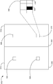
- FIG. 4 is a cross sectional view of an exemplary imaging device 302, in accordance with some embodiments.
- the imaging device 302 includes a camera body 402.
- the camera body 402 is, e.g., a body of the movable object 102, a body mounted on and/or inside of the movable object 102, a body coupled to the carrier 104 (e.g., as a payload 106) , and/or a body coupled to a payload 106.
- the camera body 402 is, e.g., a structure to which an image sensor 304 is coupled.
- the camera body 402 includes a camera body opening that admits light into the camera body 402.
- the camera body 402 is fabricated from a material that reduces or eliminates light penetration such that the camera body 402 admits light only at the camera body opening (e.g., via the optical device 306 and/or the camera lens 404) .
- the optical device 306 and/or the camera lens 404 is mounted over an opening of camera body 402.
- an optical device 306 is coupled (e.g., fixedly, movably, and/or interchangeably mounted) to camera body 402.
- the optical device 306 is depicted as a single lens that moves relative to the camera body 402
- the optical device 306 is a camera lens 404 (e.g., an optical device that is fixedly and/or detachably mounted to the camera body 402) that includes one or more optical elements (e.g., lenses) that move relative to the image sensor 304.
- the optical device 306 is mounted on the interior of the camera body 402.
- the optical device 306 moves relative to the image sensor 304 along an x-axis.
- the optical device 306 is shown (with dotted lines indicating past positions of the optical device 306) at a first position x 0 that is at a first separation distance between the optical device 306 and the image sensor 304, a second position x 1 that is at a second separation distance between optical device 306 and the image sensor 304, and a third position x 2 that is at a third separation distance between the optical device 306 and the image sensor 304.
- Optical device 306 is shown (with solid lines indicating a current position of the optical device 306) at a fourth position x 3 that is at a fourth separation distance between the optical device 306 and the image sensor 304.
- a first image is captured at first position x 0
- a second image is captured at second position x 1
- a third image is captured at first position x 2
- a fourth image is captured at first position x 3 , and so on.
- the optical device 306 is moved relative to the image sensor 304 to focus an image captured by the image sensor 304.
- the optical device 306 is moved relative to the image sensor 304 during an autofocus operation.
- the autofocus operation is a contrast detection autofocus operation.
- the contrast detection autofocus operation includes, e.g., determining a contrast variation rate for an image captured by the image sensor 304. As the contrast variation rate increases, the focus of the image captured by the image sensor 304 improves.
- a contrast variation rate is determined (e.g., based on an image captured by the image sensor 304 and at least one previous captured image) .
- the contrast variation rate is used to determine a step size for approaching a separation distance between the image sensor 304 and the optical device 306 at which the image is focused.
- autofocus can be achieved by gradually approaching a focus separation distance (e.g., an estimated separation distance between the image sensor 304 and the optical device 306 at which focus is achieved, substantially achieved, and/or maximized) .
- the new step size is, e.g., an increased step size (e.g., when the current separation distance is relatively far from the focus separation distance) or a decreased step size (e.g., when the current separation is relatively close to the focus separation distance) .
- the focus of the image captured by the image sensor 304 is iteratively improved such that the focus separation distance is approached and/or reached without the need to overshoot the focus separation distance. In this way, movement of components of the movable object 102, such as the optical device 306 and/or the image sensor 304, is reduced in comparison with autofocus techniques that rely on less precise movements and/or overshoot of a focus separation distance.
- Figure 5 illustrates contrast variation determination for an exemplary image 502 captured by the image sensor 304, in accordance with some embodiments.
- a contrast gradient is captured across one or more portions of the image 502.
- a portion of the image 502 is, e.g., a subset of pixels of the image 502, such as a 16x16 array of pixels or a 4x4 array of pixels.
- an image is divided into four quadrants and subsets of pixels are selected from one or more quadrants of the image.
- the image 502 includes subsets of pixels 504, 506, 508, and 510 corresponding to quadrants 514, 516, 518 and 520, respectively, of the image 502.
- the pixel array 512 illustrates a 4x4 array of pixels corresponding to the subset of pixels 510.
- the pixel array 512 includes pixels with a variety of luminance values.
- the pixel 522 has a low luminance value relative to the pixel 524.
- a luminance gradient across the pixels of the pixel array 512 is determined based on a variation in luminance across the pixel array 512.
- a luminance gradient value for the pixel subset 510 is determined as follows:
- determining a contrast value for the image 502 includes determining an average of luminance gradients for the pixel subsets 504, 506, 508, and 510. For example, a contrast value for the image 502 is determined as follows:
- a contrast value is determined using a pixel subset at a position corresponding to a location in the image 502 designated by a user (e.g., designated by input provided via the control unit 108 and/or the computing device 110) . In some embodiments, a contrast value is determined using a pixel subset at a position corresponding to a target or a portion of a target being tracked by the movable object 102 as captured in the image 502 (e.g., a target designated by input provided via the control unit 108 and/or the computing device 110) . In some embodiments, a contrast value is determined using luminance values of all pixels of the image 502.
- Figures 6A-6C illustrate a simplified representation of locations at which light rays corresponding to the object 602 converge based on various separation distances between the optical device 306 and the image sensor 304, in accordance with some embodiments.
- Figures 6D-6F illustrate contrast distributions corresponding to the respective separation distances illustrated in Figures 6A-6C, in accordance with some embodiments.
- Figures 6G-6I illustrate pixel arrays corresponding to the respective separation distances illustrated in Figures 6A-6C, in accordance with some embodiments.
- an autofocus operation that uses contrast value determination includes iteratively adjusting a separation distance between the optical device 306 and the image sensor 304 as a contrast value reaches a maximum value.
- an image 502 of an object 602 captured by the image sensor 304 is out of focus.
- light rays 604 corresponding to the object 602 converge at a position 606 in front of the image sensor 304 (e.g., to the right of the image sensor 304 as illustrated in Figure 6A) .
- light rays 602 converge at a position 608 behind the image sensor 304 (e.g., to the left of the image sensor 304 as illustrated in Figure 6C) .
- an image 502 captured by the image sensor 304 is in focus because light rays 604 converge at a position corresponding to the position of the image sensor 304.
- Figure 6D illustrates a contrast distribution 612 across a portion of an image 502 (e.g., at a pixel array 512) .
- the contrast distribution 612 of Figure 6D corresponds to the separation distance of the optical device 306 and the image sensor 304 shown in Figure 6A.
- Figure 6E illustrates a contrast distribution 614 across a portion of an image 502 captured when the separation distance of the optical device 306 and the image sensor 304 are as shown in Figure 6B.
- Figure 6F illustrates a contrast distribution 616 across a portion of an image 502 captured when the separation distance of the optical device 306 and the image sensor 304 is as shown in Figure 6C.
- Figure 6G illustrates a subset of pixels 618 from an image 502 captured by the image sensor 304, corresponding to the separation distance of the optical device 306 and the image sensor 304 shown in Figure 6A.
- Figure 6H illustrates a subset of pixels 620 from an image captured by the image sensor 304, corresponding to the separation distance of the optical device 306 and the image sensor 304 shown in Figure 6B.
- Figure 6I illustrates a subset of pixels 622 from an image captured by the image sensor 304, corresponding to the separation distance of the optical device 306 and the image sensor 304 shown in Figure 6C.
- the contrast value of the pixel array 620 is high, demonstrating that the difference between the highest-luminance pixels and lowest-luminance pixels increases as focus improves. This is also demonstrated by the steepness of the slope of the contrast distribution 614 relative to contrast distributions 612 and 616.
- Figure 7 illustrates contrast values y 0 , y 1 , y 2 , and y 3 obtained from images captured at separation distances x 0 , x 1 , x 2 , and x 3 , respectively, between the optical device 306 and the image sensor 304.
- separation distances x 0 , x 1 , x 2 , and x 3 of Figure 7 are separation distances x 0 , x 1 , x 2 , and x 3 , described with regard to Figure 4.
- a curve is generated based on determined contrast values y 0 , y 1 , y 2 , and y 3 .
- a generated curve is used to estimate a peak contrast value (e.g., an estimated contrast value y peak corresponding to a focus separation distance x peak between the optical device 306 and the image sensor 304.
- the generated curve is a Bézier curve, such as a cubic Bézier curve.
- a generated cubic Bézier curve is determined for (x 0 , y 0 ) , (x 1 , y 1 ) , (x 2 , y 2 ) , (x 3 , y 3 ) as follows:
- a nonlinear least squares analysis is used to find a best fit curve to (x 0 , y 0 ) , (x 1 , y 1 ) , (x 2 , y 2 ) , (x 3 , y 3 ) ... (x n , y n ) .
- Figure 8A illustrates a cubic Bézier curve 802 determined for (x 0 , y 0 ) , (x 1 , y 1 ) , (x 2 , y 2 ) , (x 3 , y 3 ) .
- An estimated point at which the contrast value is at a maximum y peak corresponds to a point at which the derivative of the curve 802 is equal to zero.
- the value t peak e.g., the value of t when y’ (t) of the cubic Bézier curve is equal to zero
- x(t peak ) x 0 (1-t peak ) 3 +3x 1 t peak (1-t peak ) 2 +3x 2 t peak 2 (1-t peak ) +x 3 t peak 3 (5)
- Figure 8B illustrates determined values (x peak , y peak ) corresponding to an estimated focus separation distance between the optical device 306 and the image sensor 304, in accordance with some embodiments.
- the determined x peak value is used for determining an increased next step value s n , as indicated below:
- total length is, for example, a maximum separation distance between the optical device 306 and the image sensor 304 (e.g., as constrained by the camera body 402 and/or the camera lens 404)
- a current separation distance between the optical device 306 and the image sensor 304 is indicated by x c .
- the separation distance between the optical device 306 and the image sensor 304 is increased from x c by the value s n , such that the distance between the optical device 306 and the image sensor 304 is increased to x n (e.g., as shown in Figure 8C) .
- x n e.g., as shown in Figure 8C
- the separation distance between the optical device 306 and the image sensor 304 has been increased to a next distance x n
- an image 502 is captured and a next contrast value y n is determined.
- Figure 8C illustrates a contrast value y n determined after the distance between the optical device 306 and the image sensor 304 has been increased to a distance x n .
- a contrast variation rate 804 (e.g., dy/dx) is determined at the point x n .
- the contrast variation rate 804 is determined as follows:
- x previous is x 3 and y previous is y 3 .
- the contrast variation rate is compared with one or more threshold values. For example, a contrast variation rate is compared with a first threshold value (e.g., threshold A) to determine whether a next step size will be an increased step size or a decreased step size. In accordance with a determination that the contrast variation rate meets a first threshold criterion (e.g., the contrast variation rate is greater than threshold A) , the next step size will be an increased step size.
- a first threshold value e.g., threshold A
- the next step size will be an increased step size.
- the next step size will be an decreased step size determined as follows:
- Figure 8D illustrates various threshold values to which determined contrast variation rates are compared, in accordance with various embodiments.
- a first threshold 806 e.g., threshold A
- a second threshold 808 e.g., threshold B
- a third threshold 810 has a third gradient.
- the absolute value of the gradient of threshold B is lower than the absolute value of the gradient of threshold A and the absolute value of the gradient of threshold C is lower than the absolute value of the gradient of threshold C.
- the contrast variation rate 804 as shown in Figure 8C is compared with the first threshold 806 as shown in Figure 8D.
- the next step size will be an increased step size determined using (6) .
- the contrast variation rate 804 (e.g., the dy/dx value of 804) is less than or equal to (e.g., as steep or less steep than) the first threshold 806 (threshold A) slope value
- the contrast variation rate 804 is compared with the second threshold 808 (threshold B) slope value.
- the next step size will be a decreased step size determined using (8) .
- a low pass filter is applied to (x 0 , y 0 ) , (x 1 , y 1 ) , (x 2 , y 2 ) , (x 3 , y 3 ) ... (x n , y n ) to obtain a filtered contrast distribution, and a gradient of the filtered contrast distribution is determined at the point x n as follows:
- the gradient of the filtered contrast distribution is compared with the third threshold 810 (threshold C) slope value. In accordance with a determination that the gradient of the filtered contrast distribution is greater than (steeper than) the third threshold 810 (threshold C) slope value, one or more of the operations described with regard to Figures 4-8D are repeated. In accordance with a determination that the gradient of the filtered contrast distribution is less than or equal to (e.g., as steep or less steep than) the third threshold 810 (threshold C) slope value, it is determined that the focus separation distance has been achieved.
- Figures 9A-9C are a flow diagram illustrating a method 900 for moving an optical device relative to an image sensor to focus an image, in accordance with some embodiments.
- the method 900 is performed at a device, such as the movable object 102, the imaging device 302, the control unit 108 and/or the computing device 110.
- instructions for performing the method 900 are stored in the memory 204 and executed by processor (s) 202.
- the device determines (902) whether the optical device 306 is at an initial position (e.g., a position x 0 at which a separation distance between the optical device 306 and the image sensor 304 is x 0 ) .
- the device captures (906) an image 502 via the image sensor 304.
- the device provides instructions to the imaging device actuator 308 to move (908) the optical device 306 to the initial position.
- the device determines (910) an initial contrast value (e.g., y 0 ) at the initial position. For example, initial contrast value y 0 is determined in accordance with equations (1) - (2) above.
- the device provides instructions to the imaging device actuator 308 to move (912) the optical device 306 to a second position (e.g., a position x 1 at which a separation distance between the optical device 306 and the image sensor 304 is x 1 ) .
- the device captures (914) a second image 502 via image sensor 304 when optical device 306 is at the second position.
- the device determines (916) a contrast value (e.g., y 1 ) at the second position.
- second contrast value y 1 is determined in accordance with equations (1) - (2) above.
- the device provides instructions to imaging device actuator 308 to move (918) the optical device 306 to a next position (e.g., a position x i at which a separation distance between the optical device 306 and the image sensor 304 is x i ) .
- a next position e.g., a position x i at which a separation distance between the optical device 306 and the image sensor 304 is x i
- the device captures (920) a next image 502 via image sensor 304 when optical device 306 is at the next position x i .
- the device determines (922) a next contrast value (e.g., y i ) at the next position.
- contrast value y i is determined in accordance with equations (1) - (2) above.
- a target number positions e.g., a predefined target number of positions
- the device In accordance with a determination that the number of positions has reached the target number of positions (e.g., contrast values y 0 , y 1 , y 2 , y 3 have been obtained) , the device generates (928) a curve. For example, the device generates a cubic Bézier curve (e.g., 802) as indicated at equation (3) .
- a cubic Bézier curve e.g. 802
- the device proceeds from operation 928 of Figure 9A to operation 930 of Figure 9B.
- the device determines (930) a peak value t peak e.g., using equation (4) .
- the device determines (932) a distance x peak based on t peak , e.g., using equation (5) .
- the device determines (934) a next step size s n , e.g., using equation (6) for an increased next step size or, (e.g., in later iterations and/or in accordance with a determination to use a decreased step size) , using equation (8) for a decreased next step size.
- the device captures (938) a next image 502 when the separation distance between the optical device 306 and the image sensor 304 is x n .
- the device determines (940) a next contrast value (e.g., y n ) at the next position.
- a next contrast value e.g., y n
- contrast value y n is determined in accordance with equations (1) - (2) above.
- the device determines (942) a contrast variation rate (e.g., as indicated at 804) at position x n .
- a contrast variation rate dy/dx is determined in accordance with equation (7) above.
- the device compares (944) the contrast variation rate determined at (942) with a threshold A (806) .
- the device proceeds from operation 944 of Figure 9B to decision diamond 946 of Figure 9C.
- the device determines (946) whether the contrast variation rate (e.g., 804) exceeds the threshold A 806 gradient value. In accordance with a determination that the contrast variation rate exceeds the threshold A gradient value, the device (948) will determine the next step size s n (e.g., at an next iteration of the operation 934) using increased next step size equation (6) . In accordance with a determination that the contrast variation rate does not exceed the threshold A slope value, the device determines (950) whether the contrast variation rate (e.g., 804) exceeds the gradient of the threshold B 808. In accordance with a determination that the contrast variation rate exceeds the threshold B gradient value, the device (952) will determine the next step size s n (e.g., at an next iteration of the operation 934) using decreased next step size equation (8) .
- the device determines (946) whether the contrast variation rate (e.g., 804) exceeds the threshold A 806 gradient value. In accordance with a determination that the contrast variation rate exceeds the
- the device proceeds from operations 948 and/or 952 of Figure 9C to the operation 954 of Figure 9B.
- the device generates a new curve using x 0 , y 0 ) , (x 1 , y 1 ) , (x 2 , y 2 ) , (x 3 , y 3 ) ... (x n , y n ) .
- a nonlinear least squares analysis is used to find a best fit curve to (x 0 , y 0 ) , (x 1 , y 1 ) , (x 2 , y 2 ) , (x 3 , y 3 ) ...
- the device applies (956) a low pass filter to (x 0 , y 0 ) , (x 1 , y 1 ) , (x 2 , y 2 ) , (x 3 , y 3 ) ... (x n , y n ) to obtain a filtered contrast distribution.
- the device determines (958) a gradient value dy/dx of the filtered contrast distribution, e.g., using equation (9) at the most recent position of the optical device 306 relative to the image sensor 304 (e.g., at x n ) .
- the device compares (960) the determined gradient value dy/dx of the filtered contrast distribution at the position x n to threshold C (810) .
- the device in accordance with a determination that the determined gradient value dy/dx of the filtered contrast distribution exceeds the threshold C gradient value, the device proceeds to operation 902 of Figure 9A, as indicated at D.
- the focus separation distance is determined to have been reached and the flow ends.
- Figures 10A and 10B illustrate exemplary contrast distributions over a range from a minimum separation distance x min between the optical device 306 and the image sensor 304 to a maximum separation distance x max between the optical device 306 and the image sensor 304.
- Figure 10A illustrates an example of a contrast distribution obtained in a high contrast setting
- Figure 10B illustrates an example of a contrast distribution obtained in a low contrast setting (e.g., a low light setting) .
- the presence of noise in a contrast distribution e.g., as demonstrated in Figure 10B, particularly in comparison with Figure 10A
- due to, e.g., low light conditions, light flicker, and/or movement of the imaging device during the autofocus process has the potential to reduce the accuracy with which a focus separation distance is determined.
- Figures 11A-11D are a flow diagram illustrating a method 1100 for moving an optical device 306 relative to an image sensor 304 to focus an image 502, in accordance with some embodiments.
- the method 1100 is performed at a device, such as the movable object 102, the imaging device 302, the control unit 108 and/or the computing device 110.
- instructions for performing the method 1100 are stored in the memory 204 and executed by the processor (s) 202.
- the device acquires (1102) , by the image sensor 304, a first image 502 when the optical device 306 is at a first position relative to the image sensor 304 (e.g., at a separation distance x n between the optical device 306 and the image sensor 304) .
- the device obtains (1104) a first contrast value y n of the first image 502 (e.g., a contrast value determined in accordance with equations (1) and/or (2) ) and a first contrast variation rate dy/dx at the first position x n (e.g., a contrast variation rate determined in accordance with equation (7) , such as the contrast variation rate illustrated at 804) .
- a first contrast value y n of the first image 502 e.g., a contrast value determined in accordance with equations (1) and/or (2)
- a first contrast variation rate dy/dx at the first position x n e.g., a contrast variation rate determined in accordance with equation (7) ,
- the device determines (1106) whether the first contrast variation rate dy/dx meets a first threshold criterion. For example, the device determines whether the first contrast variation rate dy/dx is greater than a first threshold gradient value (e.g., a threshold A gradient value as illustrated at 806 of Figure 8D) .
- a first threshold gradient value e.g., a threshold A gradient value as illustrated at 806 of Figure 8D
- the device (1108) determines a first step size s n , the first step size greater than a previous step size used for moving the optical device to the first position (e.g., equation (6) for determining an increased step size is used to determine the first step size s n ) ; and the device moves the optical device 306 from the first position to a second position according to the first step size s n (e.g., the optical device 306 is moved to a separation distance x n from the image sensor 304) .
- the device determines a second step size s n , the second step size smaller than the previous step size used for moving the optical device 306 to the first position (e.g., equation (8) for determining an decreased step size is used to determine the second step size s n ) ; and the device moves the optical device 306 from the first position to the second position according to the second step size s n (e.g., the optical device 306 is moved to a separation distance x n from the image sensor 304) .
- the first threshold gradient value such as a gradient value of threshold A as illustrated at 806 of Figure 8D
- the device repeats (1112) the aforementioned operations (e.g., 1102, 1104, 1106, 1108, and/or 1110) until a second contrast variation rate dy/dx meets a second threshold criterion (e.g., the second contrast variation dy/dx is less than (or equal to) a second threshold gradient value such as threshold B (808) ) .
- the second image 502 is acquired when the optical device 306 is at the second position (separation distance) x n+1 .
- determining that the first contrast variation rate meets the first threshold criterion includes (1114) comparing the first contrast variation rate to a first threshold gradient value.
- the first threshold gradient value is a gradient value indicating the slope of the line corresponding to threshold A, as shown at 806 of Figure 8D.
- the first contrast variation rate meets the first threshold criterion when (1116) the first contrast variation rate exceeds a first threshold gradient value.
- the first contrast variation rate meets the first threshold criterion when contrast variation rate dy/dx as determined in accordance with equation (7) exceeds a gradient value indicating the threshold A gradient value, as shown at 806 of Figure 8D.
- determining that the second contrast variation rate meets the second threshold criterion includes (1118) comparing the second contrast variation rate to a second threshold gradient value, wherein the second threshold gradient value is less than (e.g., less steep than) the first threshold gradient value.
- the second contrast variation rate meets the second threshold criterion when contrast variation rate dy/dx as determined in accordance with equation (7) exceeds a threshold B gradient value, as shown at 808 of Figure 8D.
- determining at least one of the first step size and the second step size includes (1120) : generating a curve based on a plurality of contrast values including the first contrast value (e.g., generating a curve based on y 0 , y 1 , y 2 , y 3 , y n as described with regard to 954 of Figure 9B) , determining a position (e.g., separation distance) of the optical device 306 relative to the image sensor 304 at which the curve has a peak value (e.g., determining a position x peak , as described with regard to 932) and determining the first step size s n using the determined position (e.g., x peak ) of the optical device 306 relative to the image sensor 304 at which the curve has a peak value.
- the determined x peak value is used to determine an increased step size s n as indicated in equation (6) .
- the curve in at least one iteration of the repeating operation, is a Bézier curve (1122) .
- the Bézier curve is a quadradic or higher-order Bézier curve.
- the Bézier curve is a cubic Bézier curve (1124) , e.g., the Bézier curve as defined at (3) .
- the curve is determined (1126) using a non-linear least squares analysis.
- a non-linear least squares analysis is applied to find a best fit curve to (x 0 , y 0 ) , (x 1 , y 1 ) , (x 2 , y 2 ) , (x 3 , y 3 ) ... (x n , y n ) .
- the device determines (1128) the first contrast value using at least one luminance gradient value from the first image 502, wherein a respective luminance gradient value is a luminance gradient across a portion (e.g., a 4 pixel x 4 pixel array 512, or a 16 pixel x 16 pixel array) of the first image 502.
- a contrast value is determined in accordance with equations (1) and/or (2) above.
- the device determines (1130) the first contrast value using an average of a plurality of luminance gradient values from the first image 502 (e.g., four luminance gradient values corresponding to pixel arrays 504, 506, 508, 510 from quadrants 514, 516, 518, 520, respectively, of first image 502) , as described with regard to equation (2) .
- a plurality of luminance gradient values from the first image 502 e.g., four luminance gradient values corresponding to pixel arrays 504, 506, 508, 510 from quadrants 514, 516, 518, 520, respectively, of first image 502 , as described with regard to equation (2) .
- the device in response to determining that the second contrast variation rate meets a second threshold criterion (e.g., the second contrast variation rate is less than (or equal to) the slope of second threshold B gradient value, as indicated at 808) , the device applies (1132) a filter to a plurality of obtained contrast values (x 0 , y 0 ) , (x 1 , y 1 ) , (x 2 , y 2 ) , (x 3 , y 3 ) ... (x n , y n ) . to generate a filtered curve.
- a second threshold criterion e.g., the second contrast variation rate is less than (or equal to) the slope of second threshold B gradient value, as indicated at 808
- the filter (1134) is a low pass filter.
- the low pass filter is (1136) a one-dimensional Gaussian filter.
- the device determines (1138) whether the filtered curve at the current position of the optical device 306 relative to the image sensor 304 satisfies an end criterion, and, in response to determining that the filtered curve does not satisfy the end criterion, the device initializes the optical device 306 at an initial position (e.g., x 0 ) relative to the image sensor 304 and repeats the aforementioned operations (e.g. repeats operations 1102-1112. In other words, the current autofocus attempt is aborted and the autofocus process is restarted from the initial position of the optical device 306 relative to the image sensor 304 (e.g., separation distance x 0 ) .
- various aspects of the captured images may change rapidly over time, such that if a current autofocus attempt fails it is more efficient to restart the autofocus process by collecting new contrast values rather than continuing to try to achieve focus based on previously collected contrast values.
- determining whether the filtered curve at the current position of the optical device 306 relative to the image sensor 304 satisfies the end criterion includes (1140) determining whether a gradient of the filtered curve at the current position of the optical device (e.g., as determined using equation 9) relative to the image sensor meets a third threshold criterion.
- the gradient of the filtered curve at the current position of the optical device meets a third threshold criterion when the gradient of the filtered curve at the current position of the optical device is less than (or equal to) a threshold C gradient value (e.g., as indicated at 810) .
- the second contrast variation rate dy/dx is determined (1142) using a second contrast value y n+1 obtained for a second image 502.
- the first contrast variation rate dy/dx is a gradient value indicating (1144) a rate of change of a contrast value from a previous image to a current image.
- a contrast variation rate difference is a difference (1146) between the first contrast value y n of the first image and a contrast value y previous of a previous image;
- a distance difference is a difference between a first distance x n between the optical device and the image sensor at which the first image is captured and a second distance x previous between the optical device and the image sensor at which the second image is captured;
- the rate of change of the contrast value is the contrast variation rate difference divided by the distance difference, e.g., as indicated in equation (7) .
- initializing the optical device 306 at an initial position (e.g., x 0 ) relative to the image sensor 304 includes using data generated by a depth sensor of the movable object 102 to determine an initialization distance.
- the initial position is determined based on output from a depth sensor (e.g., an image sensor, an audio sensor, and/or an infrared sensor) of the movable object sensing system 210.
- processors 202 include, without limitation, one or more general purpose microprocessors (for example, single or multi-core processors) , application-specific integrated circuits, application-specific instruction-set processors, field-programmable gate arrays, graphics processing units, physics processing units, digital signal processing units, coprocessors, network processing units, audio processing units, encryption processing units, and the like.
- general purpose microprocessors for example, single or multi-core processors
- application-specific integrated circuits for example, application-specific instruction-set processors, field-programmable gate arrays
- graphics processing units for example, single or multi-core processors
- physics processing units for example, digital signal processing units, coprocessors, network processing units, audio processing units, encryption processing units, and the like.
- FIG. 1 A block diagram illustrating an exemplary computing environment in accordance with the present invention.
- FIG. 1 A block diagram illustrating an exemplary computing environment in accordance with the present invention.
- FIG. 1 A block diagram illustrating an exemplary computing environment in accordance with the present invention.
- FIG. 1 A block diagram illustrating an exemplary computing environment in accordance with the present invention.
- FIG. 1 A block diagram illustrating an exemplary computing environment in accordance with the present inventions.
- FIG. 1 A block diagram illustrating an exemplary computing environment in accordance with the present invention.
- FIG. 1 A block diagram illustrating an exemplary computing environment in accordance with the present invention.
- FIG. 1 A block diagram illustrating an exemplary computing environment in accordance with the present invention.
- FIG. 1 A block diagram illustrating an exemplary computing environment in accordance with the present invention.
- FIG. 1 A block diagram illustrating an exemplary computing environment in accordance with the present invention.
- FIG. 1 A block diagram illustrating an exemplary computing environment in accordance with the present invention.
- the storage medium (e.g., the memory 204) can include, but is not limited to, any type of disk including floppy disks, optical discs, DVD, CD-ROMs, microdrive, and magneto-optical disks, ROMs, RAMs, EPROMs, EEPROMs, DRAMs, VRAMs, DDR RAMs, flash memory devices, magnetic or optical cards, nanosystems (including molecular memory ICs) , or any type of media or device suitable for storing instructions and/or data.
- any type of disk including floppy disks, optical discs, DVD, CD-ROMs, microdrive, and magneto-optical disks, ROMs, RAMs, EPROMs, EEPROMs, DRAMs, VRAMs, DDR RAMs, flash memory devices, magnetic or optical cards, nanosystems (including molecular memory ICs) , or any type of media or device suitable for storing instructions and/or data.
- features of the present invention can be incorporated in software and/or firmware for controlling the hardware of a processing system, and for enabling a processing system to interact with other mechanism utilizing the results of the present invention.
- software or firmware may include, but is not limited to, application code, device drivers, operating systems, and execution environments/containers.
- Communication systems as referred to herein optionally communicate via wired and/or wireless communication connections.
- communication systems optionally receive and send RF signals, also called electromagnetic signals.
- RF circuitry of the communication systems convert electrical signals to/from electromagnetic signals and communicate with communications networks and other communications devices via the electromagnetic signals.
- RF circuitry optionally includes well-known circuitry for performing these functions, including but not limited to an antenna system, an RF transceiver, one or more amplifiers, a tuner, one or more oscillators, a digital signal processor, a CODEC chipset, a subscriber identity module (SIM) card, memory, and so forth.
- SIM subscriber identity module
- Communication systems optionally communicate with networks, such as the Internet, also referred to as the World Wide Web (WWW) , an intranet and/or a wireless network, such as a cellular telephone network, a wireless local area network (LAN) and/or a metropolitan area network (MAN) , and other devices by wireless communication.
- networks such as the Internet, also referred to as the World Wide Web (WWW)
- WWW World Wide Web
- a wireless network such as a cellular telephone network, a wireless local area network (LAN) and/or a metropolitan area network (MAN)
- LAN wireless local area network
- MAN metropolitan area network
- Wireless communication connections optionally use any of a plurality of communications standards, protocols and technologies, including but not limited to Global System for Mobile Communications (GSM) , Enhanced Data GSM Environment (EDGE) , high-speed downlink packet access (HSDPA) , high-speed uplink packet access (HSUPA) , Evolution, Data-Only (EV-DO) , HSPA, HSPA+, Dual-Cell HSPA (DC-HSPDA) , long term evolution (LTE) , near field communication (NFC) , wideband code division multiple access (W-CDMA) , code division multiple access (CDMA) , time division multiple access (TDMA) , Bluetooth, Wireless Fidelity (Wi-Fi) (e.g., IEEE 102.11a, IEEE 102.11ac, IEEE 102.11ax, IEEE 102.11b, IEEE 102.11g and/or IEEE 102.11n) , voice over Internet Protocol (VoIP) , Wi-MAX, a protocol for e-mail
- the term “if” may be construed to mean “when” or “upon” or “in response to determining” or “in accordance with a determination” or “in response to detecting, ” that a stated condition precedent is true, depending on the context.
- the phrase “if it is determined [that a stated condition precedent is true] ” or “if [a stated condition precedent is true] ” or “when [a stated condition precedent is true] ” may be construed to mean “upon determining” or “in response to determining” or “in accordance with a determination” or “upon detecting” or “in response to detecting” that the stated condition precedent is true, depending on the context.
Landscapes
- Physics & Mathematics (AREA)
- Engineering & Computer Science (AREA)
- General Physics & Mathematics (AREA)
- Computer Vision & Pattern Recognition (AREA)
- Multimedia (AREA)
- Signal Processing (AREA)
- Theoretical Computer Science (AREA)
- Aviation & Aerospace Engineering (AREA)
- Optics & Photonics (AREA)
- Studio Devices (AREA)
Abstract
Des systèmes, des procédés et/ou des dispositifs sont utilisés pour déplacer un dispositif optique par rapport à un capteur d'image pour mettre au point une image. Le capteur d'image acquiert une première image. Une première vitesse de variation du contraste est obtenue. Conformément à une détermination selon laquelle la vitesse de variation du contraste satisfait à un premier critère de seuil, le dispositif optique est déplacé d'une première taille de pas qui est supérieure à une taille de pas précédente, à une seconde position. Conformément à une détermination selon laquelle le premier taux de variation de contraste ne satisfait pas au premier critère de seuil, le dispositif optique est déplacé d'une seconde taille de pas qui est inférieure à la taille de pas précédente jusqu'à la seconde position. Les opérations mentionnées ci-dessus sont répétées jusqu'à ce qu'une seconde vitesse de variation de contraste déterminée pour une seconde image acquise lorsque le dispositif optique se trouve à la seconde position satisfasse à un second critère de seuil.
Priority Applications (6)
| Application Number | Priority Date | Filing Date | Title |
|---|---|---|---|
| CN201680082952.XA CN108780261B (zh) | 2016-04-15 | 2016-04-15 | 使用自适应步长的对比度检测自动聚焦 |
| CN202011182650.4A CN112312018B (zh) | 2016-04-15 | 2016-04-15 | 使用自适应步长的对比度检测自动聚焦 |
| PCT/CN2016/079506 WO2017177465A1 (fr) | 2016-04-15 | 2016-04-15 | Mise au point par détection de contraste à l'aide d'une étape adaptative |
| US16/113,852 US10798286B2 (en) | 2016-04-15 | 2018-08-27 | Contrast detection autofocus using adaptive step |
| US17/025,949 US10944897B2 (en) | 2016-04-15 | 2020-09-18 | Contrast detection autofocus using adaptive step |
| US17/194,204 US20210211581A1 (en) | 2016-04-15 | 2021-03-05 | Contrast detection autofocus using adaptive step |
Applications Claiming Priority (1)
| Application Number | Priority Date | Filing Date | Title |
|---|---|---|---|
| PCT/CN2016/079506 WO2017177465A1 (fr) | 2016-04-15 | 2016-04-15 | Mise au point par détection de contraste à l'aide d'une étape adaptative |
Related Child Applications (1)
| Application Number | Title | Priority Date | Filing Date |
|---|---|---|---|
| US16/113,852 Continuation US10798286B2 (en) | 2016-04-15 | 2018-08-27 | Contrast detection autofocus using adaptive step |
Publications (1)
| Publication Number | Publication Date |
|---|---|
| WO2017177465A1 true WO2017177465A1 (fr) | 2017-10-19 |
Family
ID=60041285
Family Applications (1)
| Application Number | Title | Priority Date | Filing Date |
|---|---|---|---|
| PCT/CN2016/079506 Ceased WO2017177465A1 (fr) | 2016-04-15 | 2016-04-15 | Mise au point par détection de contraste à l'aide d'une étape adaptative |
Country Status (3)
| Country | Link |
|---|---|
| US (3) | US10798286B2 (fr) |
| CN (2) | CN108780261B (fr) |
| WO (1) | WO2017177465A1 (fr) |
Cited By (2)
| Publication number | Priority date | Publication date | Assignee | Title |
|---|---|---|---|---|
| CN110337609A (zh) * | 2017-10-30 | 2019-10-15 | 深圳市大疆创新科技有限公司 | 控制装置、镜头装置、摄像装置、飞行体以及控制方法 |
| WO2021080524A1 (fr) * | 2019-10-23 | 2021-04-29 | Aselsan Elektroni̇k Sanayi̇ Ve Ti̇caret Anoni̇m Şi̇rketi̇ | Procédé d'optimisation de mise au point passive et adaptative pour un système optique |
Families Citing this family (7)
| Publication number | Priority date | Publication date | Assignee | Title |
|---|---|---|---|---|
| JP6735917B2 (ja) * | 2017-05-16 | 2020-08-05 | 富士フイルム株式会社 | 撮像装置及び画像合成装置 |
| JP6798072B2 (ja) * | 2019-04-24 | 2020-12-09 | エスゼット ディージェイアイ テクノロジー カンパニー リミテッドSz Dji Technology Co.,Ltd | 制御装置、移動体、制御方法、及びプログラム |
| CN110381261B (zh) * | 2019-08-29 | 2020-11-03 | 重庆紫光华山智安科技有限公司 | 聚焦方法、装置、计算机可读存储介质及电子设备 |
| CN112525909B (zh) * | 2020-12-03 | 2025-01-14 | 湖南伊鸿健康科技有限公司 | 一种电子显微镜的自动对焦方法 |
| CN114354630B (zh) | 2022-01-07 | 2025-03-25 | 京东方科技集团股份有限公司 | 一种图像获取系统、方法及显示面板加工设备 |
| CN114544004A (zh) * | 2022-02-25 | 2022-05-27 | 浙江天铂云科光电股份有限公司 | 一种用于红外热像仪的自动聚焦方法 |
| CN119012010B (zh) * | 2024-10-25 | 2025-01-24 | 四川国创新视超高清视频科技有限公司 | 一种自动聚焦控制方法及其控制系统 |
Citations (4)
| Publication number | Priority date | Publication date | Assignee | Title |
|---|---|---|---|---|
| CN102129146A (zh) * | 2010-01-12 | 2011-07-20 | 株式会社尼康 | 摄像装置 |
| CN102629978A (zh) * | 2012-03-26 | 2012-08-08 | 深圳英飞拓科技股份有限公司 | 一种通过自动聚焦来检测靶面平整度的高清网络半球 |
| CN103235397A (zh) * | 2013-04-28 | 2013-08-07 | 华为技术有限公司 | 一种自动对焦方法及设备 |
| EP2648401A1 (fr) * | 2010-12-01 | 2013-10-09 | NEC CASIO Mobile Communications, Ltd. | Terminal mobile, procédé et programme de traitement d'image |
Family Cites Families (12)
| Publication number | Priority date | Publication date | Assignee | Title |
|---|---|---|---|---|
| US5005086A (en) * | 1988-03-04 | 1991-04-02 | Sony Corporation | Focus control apparatus having two focusing speeds |
| US5070408A (en) * | 1989-05-19 | 1991-12-03 | Sony Corporation | Focusing apparatus and digital filters for use therewith |
| JP2006047602A (ja) * | 2004-08-04 | 2006-02-16 | Casio Comput Co Ltd | カメラ装置 |
| JP2007010898A (ja) * | 2005-06-29 | 2007-01-18 | Casio Comput Co Ltd | 撮像装置及びそのプログラム |
| US20080136958A1 (en) * | 2006-12-11 | 2008-06-12 | Pentax Corporation | Camera having a focus adjusting system and a face recognition function |
| TWI324015B (en) * | 2006-12-22 | 2010-04-21 | Ind Tech Res Inst | Autofocus searching method |
| JP2008228185A (ja) * | 2007-03-15 | 2008-09-25 | Fujifilm Corp | 撮像装置 |
| JP5322783B2 (ja) * | 2009-06-05 | 2013-10-23 | キヤノン株式会社 | 撮像装置及び該撮像装置の制御方法 |
| JP5195660B2 (ja) * | 2009-06-15 | 2013-05-08 | カシオ計算機株式会社 | 撮像装置、合焦方法及びプログラム |
| JP2016118634A (ja) * | 2014-12-19 | 2016-06-30 | オリンパス株式会社 | 撮影装置及び撮影方法 |
| US9826156B1 (en) * | 2015-06-16 | 2017-11-21 | Amazon Technologies, Inc. | Determining camera auto-focus settings |
| US10761294B2 (en) * | 2015-06-18 | 2020-09-01 | Sony Corporation | Display control device and display control method |
-
2016
- 2016-04-15 WO PCT/CN2016/079506 patent/WO2017177465A1/fr not_active Ceased
- 2016-04-15 CN CN201680082952.XA patent/CN108780261B/zh not_active Expired - Fee Related
- 2016-04-15 CN CN202011182650.4A patent/CN112312018B/zh not_active Expired - Fee Related
-
2018
- 2018-08-27 US US16/113,852 patent/US10798286B2/en not_active Expired - Fee Related
-
2020
- 2020-09-18 US US17/025,949 patent/US10944897B2/en active Active
-
2021
- 2021-03-05 US US17/194,204 patent/US20210211581A1/en not_active Abandoned
Patent Citations (4)
| Publication number | Priority date | Publication date | Assignee | Title |
|---|---|---|---|---|
| CN102129146A (zh) * | 2010-01-12 | 2011-07-20 | 株式会社尼康 | 摄像装置 |
| EP2648401A1 (fr) * | 2010-12-01 | 2013-10-09 | NEC CASIO Mobile Communications, Ltd. | Terminal mobile, procédé et programme de traitement d'image |
| CN102629978A (zh) * | 2012-03-26 | 2012-08-08 | 深圳英飞拓科技股份有限公司 | 一种通过自动聚焦来检测靶面平整度的高清网络半球 |
| CN103235397A (zh) * | 2013-04-28 | 2013-08-07 | 华为技术有限公司 | 一种自动对焦方法及设备 |
Cited By (4)
| Publication number | Priority date | Publication date | Assignee | Title |
|---|---|---|---|---|
| CN110337609A (zh) * | 2017-10-30 | 2019-10-15 | 深圳市大疆创新科技有限公司 | 控制装置、镜头装置、摄像装置、飞行体以及控制方法 |
| US10942331B2 (en) | 2017-10-30 | 2021-03-09 | SZ DJI Technology Co., Ltd. | Control apparatus, lens apparatus, photographic apparatus, flying body, and control method |
| CN110337609B (zh) * | 2017-10-30 | 2021-06-11 | 深圳市大疆创新科技有限公司 | 控制装置、镜头装置、摄像装置、飞行体以及控制方法 |
| WO2021080524A1 (fr) * | 2019-10-23 | 2021-04-29 | Aselsan Elektroni̇k Sanayi̇ Ve Ti̇caret Anoni̇m Şi̇rketi̇ | Procédé d'optimisation de mise au point passive et adaptative pour un système optique |
Also Published As
| Publication number | Publication date |
|---|---|
| CN108780261A (zh) | 2018-11-09 |
| CN112312018B (zh) | 2022-05-17 |
| US20190014265A1 (en) | 2019-01-10 |
| US20210006728A1 (en) | 2021-01-07 |
| CN112312018A (zh) | 2021-02-02 |
| US10944897B2 (en) | 2021-03-09 |
| US10798286B2 (en) | 2020-10-06 |
| CN108780261B (zh) | 2020-11-17 |
| US20210211581A1 (en) | 2021-07-08 |
Similar Documents
| Publication | Publication Date | Title |
|---|---|---|
| US10944897B2 (en) | Contrast detection autofocus using adaptive step | |
| US11019255B2 (en) | Depth imaging system and method of rendering a processed image to include in-focus and out-of-focus regions of one or more objects based on user selection of an object | |
| US10930000B2 (en) | Method and system for detecting and tracking objects using characteristic points | |
| US10958822B2 (en) | Autofocus initialization based on target detection | |
| US11049261B2 (en) | Method and system for creating video abstraction from image data captured by a movable object | |
| US20190265734A1 (en) | Method and system for image-based object detection and corresponding movement adjustment maneuvers | |
| WO2018049643A1 (fr) | Procédé et système de fonctionnement d'un objet mobile pour éviter des obstacles | |
| US11320817B2 (en) | Target-based image exposure adjustment | |
| US20210074017A1 (en) | Method and system for detecting obstructive object at projected locations within images | |
| US20210392299A1 (en) | Method and system for handling image data | |
| US11130593B2 (en) | Optical path length adjustment |
Legal Events
| Date | Code | Title | Description |
|---|---|---|---|
| NENP | Non-entry into the national phase |
Ref country code: DE |
|
| 121 | Ep: the epo has been informed by wipo that ep was designated in this application |
Ref document number: 16898283 Country of ref document: EP Kind code of ref document: A1 |
|
| 122 | Ep: pct application non-entry in european phase |
Ref document number: 16898283 Country of ref document: EP Kind code of ref document: A1 |