WO2017179228A1 - Dispositif de détection de fuite - Google Patents
Dispositif de détection de fuite Download PDFInfo
- Publication number
- WO2017179228A1 WO2017179228A1 PCT/JP2016/080623 JP2016080623W WO2017179228A1 WO 2017179228 A1 WO2017179228 A1 WO 2017179228A1 JP 2016080623 W JP2016080623 W JP 2016080623W WO 2017179228 A1 WO2017179228 A1 WO 2017179228A1
- Authority
- WO
- WIPO (PCT)
- Prior art keywords
- body surface
- blood vessel
- value
- detection device
- temperature
- Prior art date
- Legal status (The legal status is an assumption and is not a legal conclusion. Google has not performed a legal analysis and makes no representation as to the accuracy of the status listed.)
- Ceased
Links
Images

Classifications
-
- A—HUMAN NECESSITIES
- A61—MEDICAL OR VETERINARY SCIENCE; HYGIENE
- A61M—DEVICES FOR INTRODUCING MEDIA INTO, OR ONTO, THE BODY; DEVICES FOR TRANSDUCING BODY MEDIA OR FOR TAKING MEDIA FROM THE BODY; DEVICES FOR PRODUCING OR ENDING SLEEP OR STUPOR
- A61M5/00—Devices for bringing media into the body in a subcutaneous, intra-vascular or intramuscular way; Accessories therefor, e.g. filling or cleaning devices, arm-rests
- A61M5/14—Infusion devices, e.g. infusing by gravity; Blood infusion; Accessories therefor
- A61M5/168—Means for controlling media flow to the body or for metering media to the body, e.g. drip meters, counters ; Monitoring media flow to the body
- A61M5/16831—Monitoring, detecting, signalling or eliminating infusion flow anomalies
-
- A—HUMAN NECESSITIES
- A61—MEDICAL OR VETERINARY SCIENCE; HYGIENE
- A61M—DEVICES FOR INTRODUCING MEDIA INTO, OR ONTO, THE BODY; DEVICES FOR TRANSDUCING BODY MEDIA OR FOR TAKING MEDIA FROM THE BODY; DEVICES FOR PRODUCING OR ENDING SLEEP OR STUPOR
- A61M5/00—Devices for bringing media into the body in a subcutaneous, intra-vascular or intramuscular way; Accessories therefor, e.g. filling or cleaning devices, arm-rests
- A61M5/14—Infusion devices, e.g. infusing by gravity; Blood infusion; Accessories therefor
- A61M5/168—Means for controlling media flow to the body or for metering media to the body, e.g. drip meters, counters ; Monitoring media flow to the body
- A61M5/16831—Monitoring, detecting, signalling or eliminating infusion flow anomalies
- A61M5/16836—Monitoring, detecting, signalling or eliminating infusion flow anomalies by sensing tissue properties at the infusion site, e.g. for detecting infiltration
-
- A—HUMAN NECESSITIES
- A61—MEDICAL OR VETERINARY SCIENCE; HYGIENE
- A61M—DEVICES FOR INTRODUCING MEDIA INTO, OR ONTO, THE BODY; DEVICES FOR TRANSDUCING BODY MEDIA OR FOR TAKING MEDIA FROM THE BODY; DEVICES FOR PRODUCING OR ENDING SLEEP OR STUPOR
- A61M2205/00—General characteristics of the apparatus
- A61M2205/15—Detection of leaks
-
- A—HUMAN NECESSITIES
- A61—MEDICAL OR VETERINARY SCIENCE; HYGIENE
- A61M—DEVICES FOR INTRODUCING MEDIA INTO, OR ONTO, THE BODY; DEVICES FOR TRANSDUCING BODY MEDIA OR FOR TAKING MEDIA FROM THE BODY; DEVICES FOR PRODUCING OR ENDING SLEEP OR STUPOR
- A61M2205/00—General characteristics of the apparatus
- A61M2205/18—General characteristics of the apparatus with alarm
-
- A—HUMAN NECESSITIES
- A61—MEDICAL OR VETERINARY SCIENCE; HYGIENE
- A61M—DEVICES FOR INTRODUCING MEDIA INTO, OR ONTO, THE BODY; DEVICES FOR TRANSDUCING BODY MEDIA OR FOR TAKING MEDIA FROM THE BODY; DEVICES FOR PRODUCING OR ENDING SLEEP OR STUPOR
- A61M2205/00—General characteristics of the apparatus
- A61M2205/50—General characteristics of the apparatus with microprocessors or computers
- A61M2205/52—General characteristics of the apparatus with microprocessors or computers with memories providing a history of measured variating parameters of apparatus or patient
-
- A—HUMAN NECESSITIES
- A61—MEDICAL OR VETERINARY SCIENCE; HYGIENE
- A61M—DEVICES FOR INTRODUCING MEDIA INTO, OR ONTO, THE BODY; DEVICES FOR TRANSDUCING BODY MEDIA OR FOR TAKING MEDIA FROM THE BODY; DEVICES FOR PRODUCING OR ENDING SLEEP OR STUPOR
- A61M2230/00—Measuring parameters of the user
- A61M2230/50—Temperature
Definitions
- the present invention relates to a leak detection device, and more particularly to a device for detecting that an injection solution to be injected into a blood vessel leaks out of the blood vessel.
- an injection solution when an injection solution is administered to a patient by infusion, if the syringe is not sufficiently fixed, or if the patient moves the puncture site, the injection needle may come out of the blood vessel or penetrate the blood vessel. Therefore, the drug solution may not be normally injected into the blood vessel.
- an anticancer drug that is an injection solution leaks into the body outside the blood vessel without being injected into the blood vessel, so-called extravasation occurs, and if the discovery is delayed, an accident such as necrosis of the tissue at the leakage site will occur. Resulting in.
- Patent Document 1 discloses a technique for detecting the occurrence of extravasation. This technique is a detection technique using thermography, where the periphery of the puncture site is imaged by thermography, the body temperature in the imaging range is measured, and when a certain temperature change occurs in the imaging range, extravascular The alarm device is activated for the leak.
- thermography is an apparatus that images the periphery of the puncture unit from a fixed point, for example, if the patient moves carelessly, the periphery of the puncture unit is out of the imaging range, and the body temperature cannot be measured. Moreover, even if the periphery of the puncture part is covered with clothing or a futon, the body temperature around the puncture part cannot be measured normally. As described above, the above technique imposes severe restrictions on the imaging conditions for enabling detection of extravasation, and accordingly, the patient's operation is more than necessary while receiving an infusion. Limited to
- an object of the present invention is to provide a liquid leakage detection device in which the restriction on the movement of a patient while receiving an injection is more relaxed than in the past.
- a leak detection device for detecting that an injection solution to be injected into a blood vessel leaks out of the blood vessel, and the periphery of the puncture portion of the injection needle for injecting the injection solution.
- the acquisition unit that acquires the value indicating the body surface temperature at the attachment location of the thermal sensor based on the output of the thermal sensor that is attached to the body surface of the thermal sensor, and the acquired value is And a determination unit that determines that the injection solution has leaked out of the blood vessel when the body surface temperature deviates from the normal temperature at the sticking location.
- a notification unit that notifies that the injection solution has leaked out of the blood vessel is provided.
- the thermal sensor is a plurality of thermal elements, and the thermal sensors are distributed and attached to both sides of the blood vessel through which the injection needle is punctured.
- the thermal sensor is attached to the body surface around the puncture part, the body surface temperature around the puncture part can be directly sensed. Therefore, even if the patient moves carelessly or the puncture part is covered with a futon or the like, the body surface temperature can be normally detected. Then, leakage of the injection solution is determined based on the body surface temperature. Thus, the behavior of the patient receiving the injection is not unnecessarily restricted.
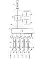
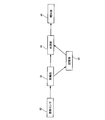
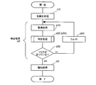
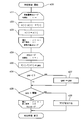
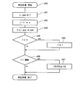
- FIG. Hardware configuration diagram of the liquid leakage detection device Block diagram of the leak detector Flow chart showing the operation of the leak detector Flow chart showing determination process in the above process
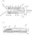
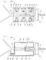
- (b) Sectional drawing of a thermal element A) The figure which shows the thermal sensor which concerns on a modification, (b) The figure which shows the thermal sensor which concerns on a modification
- the leak detection device 2 leaks an injection solution such as an anticancer drug to be injected into a blood vessel 4 such as an arm from the blood vessel 4 (hereinafter, “ This is used to detect “extravasation of injection solution”) and is used together with an infusion device 100 for injecting the injection solution into the blood vessel 4.
- the infusion device 100 includes a container (not shown) containing an injection solution, and an infusion set 6 that carries the injection solution from the container to a patient through devices such as an infusion pump (not shown) and an infusion controller (not shown). It is configured.
- a syringe 10 is connected to the distal end of a patient line 8 (a portion between the device and the patient) serving as a flow path for an injection solution, and an injection needle 12 punctures the blood vessel 4 of the patient.
- a patient line 8 a portion between the device and the patient
- an injection needle 12 punctures the blood vessel 4 of the patient.
- the tip portion of the syringe 10 and the patient line 8 is fixed by a tape 14 so as to be along the patient's body surface.
- the thermal sensor 92 (FIG. 3) provided in the liquid leakage detection device 2 includes a plurality of thermocouples 18 (six in this example) that are thermal elements, and each of the thermocouples 18 is attached to the body surface. In this example, three pieces are distributed and attached to both sides of the blood vessel 4 around the puncture portion 16 where the injection needle 12 has been punctured.
- the thermocouple 18 includes a + side conductor 20, a ⁇ side conductor 22, and a base sheet 50 made of an insulator that supports both the conductors 20 and 22 on the lower side. One end portions of the + side conductor 20 and the ⁇ side conductor 22 are connected to each other and function as a temperature measuring contact 28.
- thermocouple 18 is attached to the body surface with a double-sided tape or an adhesive provided on the lower surface of the base sheet 50. Therefore, the body surface temperature of the sticking location can be sensed by the thermocouple 18.
- the thermocouple 18 may include a cover sheet made of an insulator that covers and seals both the conductors 20 and 22. In addition, when distinguishing each of the thermocouple 18, it shall attach
- thermocouple 18 As shown in FIG. 2, the + side conductor 20 and the ⁇ side conductor 22 of each thermocouple 18 are connected to the input of the amplifying circuit 26 via the compensation conductor 24. As a result, the thermoelectromotive force generated at the temperature measuring contact 28 of each thermocouple 18 is input to the amplifier circuit 26.
- the amplifier circuit 26 amplifies the thermoelectromotive force so as to be suitable for an input range of an analog-digital conversion circuit (hereinafter referred to as “ADC”, which is denoted by a symbol “30”).
- ADC analog-digital conversion circuit
- the output of each amplifier circuit 26 is connected to the ADC 30.
- the ADC 30 is a circuit that converts an analog signal input from the amplifier circuit 26 into a digital signal based on control from the microcomputer 32, and is electrically connected to the microcomputer 32.
- the microcomputer 32 causes the ADC 30 to perform the above conversion at a predetermined timing, and receives the converted digital signal, whereby a value indicating the body surface temperature at that time (hereinafter, “current temperature”). Value)). Therefore, the amplifier circuit 26, the ADC 30, and the microcomputer 32 function as an acquisition unit 34 (FIG. 3) that acquires the current temperature value based on the thermoelectromotive force of each thermocouple 18.
- the microcomputer 32 also has an output unit (not shown) that outputs a sound signal, and an alarm sound signal output from the output unit is input to the speaker 36.
- the speaker 36 generates an alarm based on the input alarm sound signal to notify that extravascular leakage has occurred.
- the microcomputer 32 and the speaker 36 function as an informing unit 46 (FIG. 3) for informing that extravasation has occurred.
- the microcomputer 32 includes a central processing unit (hereinafter referred to as “CPU”, which is denoted by reference numeral “38”), a ROM 40, and a RAM 42.
- CPU central processing unit
- ROM 40 read-only memory
- RAM 42 random access memory
- the ROM 40 stores a program.
- an initialization process (FIG. 4), a detection process (FIG. 4), and a notification process (FIG. 4), which will be described later, are executed.
- the body surface temperature at each attachment location of each thermocouple 18 is repeatedly sampled, and each time the sampling is performed, the difference between the body surface temperature obtained at that time and the body surface temperature obtained by the latest sampling ( The body surface temperature fluctuation amount) is obtained, and the difference between the fluctuation amounts of each sticking point is compared with a threshold value to check whether the body surface temperature has deviated from the normal temperature. It is determined that an outside leak has occurred.
- the microcomputer 32 functions as the determination unit 44 (FIG. 3) that determines extravascular leakage.
- normal temperature is body surface temperature which changes naturally when extravasation does not occur.
- the above threshold value is a reference value for determining whether or not the body surface temperature sensed by any of the plurality of thermocouples 18 deviates from the normal temperature.
- the threshold value is determined based on a result of sampling the body surface temperature by experimentally instilling in advance. Specifically, the body surface temperature is repeatedly sampled at a plurality of locations around the puncture portion 16 while confirming that no extravasation has occurred. Every time sampling is performed, the amount of fluctuation of the body surface temperature at each sticking location is calculated, and the difference in the amount of fluctuation between the sticking locations is determined in a brute force manner. A maximum value is extracted from a plurality of differences in variation obtained by repeated sampling, and this maximum value is set as a threshold value.
- a variable c [i] for storing the current temperature value at the attachment location of the thermocouple 18, (b) the latest (previous sampling at the attachment location of the thermocouple 18) acquired in the sampling.
- Variable p [i] for storing a value indicating the body surface temperature (hereinafter referred to as “nearest temperature value”) acquired in step (b), (c) variation in body surface temperature at the location where the thermocouple 18 is attached.
- a variable f [i] is stored, (d) a variable gap that stores the absolute value of the difference between the fluctuation amounts, and (e) a region that stores a flag indicating whether or not extravasation has occurred is provided. It has been.
- thermocouples 18a to 18f are values corresponding to the thermocouples 18a to 18f.
- the ROM 40 and the RAM 42 function as the storage unit 48 (FIG. 3) that stores the threshold value and each variable.
- the CPU 38 of the microcomputer 32 executes an initialization process (s10) for storing an initial value in each of the variables provided in the RAM. Specifically, initial values “0” are stored in the variables c [1] to c [6], the variables f [1] to f [6], the variable gap, and the flag. As the initial values of the variables p [1] to p [6], the current temperature values at the locations where the thermocouples 18a to 18f are attached are stored. That is, a process similar to the current temperature value acquisition process (s210) described later is also executed in the initialization process (s10) to acquire the current temperature value.
- the CPU 38 of the microcomputer 32 executes a detection process (s20).
- the detection process (s20) the acquisition process (s210), the determination process (s220), and the flag check (s230) are executed in this order.
- the current temperature value acquisition process (s210) is a process of acquiring the current temperature value of each sticking location of each thermocouple 18.
- the CPU 38 inputs a conversion request signal to the ADC 30.
- the conversion request signal is a signal for instructing conversion of an analog signal
- the ADC 30 converts the analog signal corresponding to the thermocouple 18a into a digital signal and outputs the digital signal.
- the CPU 38 analyzes the digital signal, acquires the current temperature value, and stores it in the variable c [1].
- the CPU 38 performs these processes for each of the signals corresponding to the thermocouples 18b to 18f, and stores the acquired current temperature values in the variables c [2] to [6].
- the fluctuation amount calculation loop (s221) is a process for calculating the fluctuation amount of the body surface temperature at the attachment location of the thermocouple 18, and specifically, the stored value (current temperature value) of the variable c [i]. ) Is subtracted from the stored value (most recent temperature value) of the variable p [i] to obtain the amount of fluctuation, and this amount of fluctuation is stored in the variable f [i] (s222).
- a replacement process for storing the stored value of the variable c [i] in the variable p [i] is performed (s223). These processes are performed with the value of “i” from 1 to 6.
- the comparison loop (s224) is a process for comparing the calculated fluctuation amounts with each other and checking whether or not the difference exceeds a threshold value. Specifically, it is as follows.
- the initial value of the loop variable “i” is set to “1” (s224).
- the stored value of the variable gap is negative (s226: yes)
- the sign is inverted by multiplying the variable gap by -1. Thereby, the absolute value of the difference between the fluctuation amounts is stored in the variable gap (s227). Thereafter, the process proceeds to comparison with a threshold value (s228).
- the stored value of the variable gap is compared with the threshold value (s228). (6) If the stored value of the variable gap is smaller than the threshold (s228: no) as a result of comparing the magnitudes, the above processing (until the value of the loop variable “i” is incremented to 6) ( s225 to s228) are performed, and when the value becomes 6, the determination process (s220) is terminated. (7) On the other hand, if the stored value of the variable gap is larger than the threshold value (s228: yes) as a result of comparing the magnitudes, a flag is set on the assumption that the body surface temperature has deviated from the normal temperature (s229), and determination processing ( s220) is terminated.
- the CPU 38 checks whether or not a flag is set (s230). If the flag is not set (s230: no), the process waits (s240) until the sampling period elapses, and returns to the acquisition process (s210).
- the CPU 38 executes a notification process (s30). Specifically, the CPU 38 inputs an alarm sound signal for notifying extravasation to the speaker 36 through the output unit. As a result, an alarm sound is output from the speaker 36.
- the leak detection device 2 uses a plurality of (six in this example) thermocouples 18 to reduce the body surface temperature that occurs when an injection solution having a temperature lower than the body temperature leaks out of the blood vessel 4. Can be detected. For example, when extravascular leakage occurs near the thermocouple 18d, the thermoelectromotive force of the thermocouple 18d is significantly reduced as compared with the other thermocouples 18a to 18c, 18e, and 18f. Then, the current temperature value corresponding to the thermocouple 18d is significantly lower than the others.
- thermocouples 18a to 18f when the fluctuation amount of the body surface temperature at each attachment location of each of the thermocouples 18a to 18f is calculated and the fluctuation amounts are compared, the fluctuation amounts corresponding to the other thermocouples 18a to 18c, 18e, and 18f are calculated. However, the difference between the fluctuation amount corresponding to the thermocouple 18d and the fluctuation amount corresponding to the other thermocouple 18c increases and exceeds the threshold. When the threshold is exceeded, a flag is set and an alarm sound is output from the speaker 36 in the notification process (s30). For this reason, a patient and a nurse can know extravasation.
- the body surface temperature around the puncture unit can be directly sensed. . Therefore, even when the patient moves to pick up an object or the puncture portion 16 is covered with a futon or the like, the body surface temperature can be normally detected. Then, leakage of the injection solution is determined based on the body surface temperature. Therefore, the behavior of the patient receiving the infusion is not limited more than necessary.
- the thermal sensor 92 is configured by a plurality of thermocouples 18.
- the single thermocouple 18 configures the thermal sensor.
- the configuration different from that of the first embodiment will be described in detail, and the description of the common configuration will be omitted or simply referred to.
- thermocouple 18 is attached to an arbitrary location around the puncture portion 16 of the injection needle 12.
- the thermoelectromotive force generated at the temperature measuring contact 28 of the thermocouple 18 is input to one of the amplifier circuits 26 via the compensation lead 24.
- the thermoelectromotive force amplified by the amplifier circuit 26 is converted into a digital signal by the ADC 30 and input to the microcomputer 32.
- the ROM 40 of the microcomputer 32 stores a program having a determination process different from that of the first embodiment.
- the determination process (s250) of this embodiment (FIG. 6) every time the body surface temperature is sampled by repeatedly sampling the body surface temperature at the attachment location of the thermocouple 18, the body surface temperature is sampled. Calculate the amount of fluctuation with the average body surface temperature, and check whether the body surface temperature has deviated from the normal temperature depending on whether the amount of fluctuation exceeds a threshold. It is determined that extravasation has occurred.
- the above-mentioned threshold value is obtained by repeatedly sampling the body surface temperature around the puncture unit 16 experimentally in advance and confirming that no extravasation has occurred. And the maximum value among a plurality of fluctuation amounts obtained in the experiment is determined as a threshold value.
- a variable c for storing the current temperature value
- a value indicating the average value of the body surface temperature at the attachment location of the thermocouple 18 (hereinafter referred to as “average temperature value”). )
- a variable f for storing the fluctuation amount of the current temperature value with respect to the average temperature value
- a variable n for storing the number of calculation of the average temperature value
- a flag for storing the number of calculation of the average temperature value
- the CPU 38 of the microcomputer 32 executes an initialization process (s10), a detection process (s20), and a notification process (s30) shown in FIG.
- the current temperature value is acquired and stored in c as in the embodiment.
- the process is performed as shown in FIG. (1)
- the stored value (current temperature value) of variable c is subtracted from the stored value (average temperature value) of variable ave, and the result is stored in variable f (s251). Thereby, the fluctuation amount of the body surface temperature in the attachment location of the thermocouple 18 is stored in the variable f.
- the stored value of the variable n is incremented (s252), the product is obtained by multiplying the stored value of the variable n by 1 / n, and the average temperature value is obtained by adding the stored value of the variable ave to the product. Updated.
- the updated average temperature value is stored in the variable ave (s253).
- the CPU 38 After executing the determination process (s250), the CPU 38 confirms the contents of the flag, and when the flag is not set (s230: no), after performing the wait (s240), the acquisition process Return to (s210). On the other hand, when the flag is set (s230: yes), the CPU 38 inputs an alarm sound signal for notifying the extravascular leakage to the speaker 36 through the output unit. As a result, an alarm sound is output from the speaker 36.
- thermocouple 18 since there is one thermocouple 18, the configuration of the device can be simplified.
- Embodiment 1 and Embodiment 2 has been described, the present invention is not limited to the above-described aspect, and may be an aspect described below as a modified example.
- Modification 1 In the determination process (s220) of the first embodiment, the fluctuation amount of each installation location of the thermocouple 18 is calculated, the maximum value and the minimum value of the fluctuation amount are obtained, and whether or not the difference between the maximum value and the minimum value exceeds the threshold value. May be used to examine the conspicuous fluctuations in body surface temperature.
- the latest temperature value of the first embodiment is calculated instead of the average temperature value, and the difference between the latest temperature value and the current temperature value exceeds a threshold value. It may be determined depending on whether or not.
- the threshold value used in the determination process is, for example, an infusion that is experimentally performed in advance, and causes extravasation using an injection solution that is harmless to the human body and lower than the body temperature.
- the body surface temperature before and after the sampling may be sampled and determined based on the fluctuation amount of the body surface temperature.
- the leak detection device may use a known reference junction compensator instead of the ADC 30.
- the input of the reference junction compensator is connected to the thermocouple 18 via the compensation conductor 24, and the output of the reference junction compensator is connected to the microcomputer 32.
- CPU38 of the microcomputer 32 acquires the body surface temperature of each sticking location of each thermocouple 18 in an acquisition process (s210), and uses the acquired body surface temperature as a threshold value in a determination process (s220, s250). Compare. In this comparison, when the body surface temperature is lower than the lower limit value of the normal temperature or higher than the upper limit value of the normal temperature, a flag is set as deviating from the normal temperature.
- the output unit of the microcomputer 32 may output a video signal, and the liquid leakage detection device may include a display connected to the output unit.
- the flag when the flag is set (s230: yes), the CPU 38 of the microcomputer 32 inputs a video signal for informing the extravascular leakage to the display through the output unit. As a result, the display indicates that extravasation has occurred.
- the output unit of the microcomputer 32 may output a communication signal, and the liquid leakage detection device may include a network interface connected to the output unit.
- the CPU 38 of the microcomputer 32 outputs a communication signal for notifying the extravasation from the output unit, and is connected to the network via the network interface.
- the in-hospital terminal is, for example, a portable information terminal owned by a nurse or a nurse call terminal. Thereby, it can be notified to the nurse in circulation and the nurse who is waiting in the nurse station that extravasation has occurred.
- a heat sensitive element 52 is formed by laminating a + side conductor 56, an intervening film 58, a copper pad 60, and a ⁇ side conductor 62 in this order on a tape-like base sheet 54 made of an insulator. May be.
- An adhesive layer 64 is formed on the lower surface of the base sheet 54, and the thermal element 52 is adhered to the body surface by the adhesive layer 64.
- the + side conductor 56 is laminated over the entire upper surface of the base sheet 54. One end portion of the upper surface of the + side conductor 56 is exposed, and the + side compensating conductor 24 is connected to the exposed portion 66.
- the intervening film 58 is made of a resin such as polyimide, and is laminated on the upper surface of the + side conductor 56 with the exposed portion 66 of the + side conductor 56 being separated.
- the intervening film 58 has a square shape in which each side is substantially equal to the width of the + side conductor 56, and a typical thickness is 50 ⁇ m.
- a copper pad 60 is laminated at the center of the upper surface of the intervening film 58.
- the copper pad 60 is connected to the negative-side compensation conductor 24.
- the ⁇ side conductor 62 extends in a straight line from the center of the upper surface of the copper pad 60 to the other end of the + side conductor 56.
- thermosensitive element 52 having the above-described configuration, the contact surface between the + side conductor 56 and the ⁇ side conductor 62 is long, and the Seebeck effect is generated in the entire contact surface, so that it functions in the same manner as the temperature measuring contact of the thermocouple. be able to.
- the body surface temperature can be sensed in a wide range (long range) along the blood vessel 4.
- a thermal sensor 90 in which a plurality of (six in this example) temperature measuring contacts 74 are provided on a base sheet 68 made of an insulator that extends over the blood vessel 4. It may be.
- An adhesive layer (not shown) is formed on the lower surface of the base sheet 68, and the thermal sensor 90 is adhered to the body surface by the adhesive layer.
- the base sheet 68 includes a pair of tape portions 70 that are arranged on both sides of the blood vessel 4 and extend along the blood vessel 4, and a connecting portion 72 that connects one end side of the pair of tape portions 70.
- a gap is formed between the other end sides of the pair of tape portions 70, and the syringe 10 is disposed in the gap.
- a plurality (six in this example) of temperature measuring contacts 74 are distributed and arranged on each of the pair of tape portions 70.
- Each of the temperature measuring contacts 74 is formed by a + side conductor 76 and a ⁇ side conductor 78.
- Each of the + side conductor 76 and each of the ⁇ side conductors 78 extends inward from a plurality of copper pads 60 formed on the edge of the base sheet 68, and the tips of the + side conductor 76 and the ⁇ side conductor 78 are connected to each other.
- the + side conductor 82 and the ⁇ side conductor 86 are formed on the pair of tape portions 70 and the connecting portion 72 of the base sheet 96 made of an insulator that extends over the blood vessel 4.
- the thermal sensor 88 may be stacked in this order.
- An adhesive layer (not shown) is formed on the lower surface of the base sheet 96, and the thermal sensor 88 is adhered to the body surface by the adhesive layer.
- the base sheet 96 has a terminal portion 80 in addition to the pair of tape portions 70 and the connecting portion 72.
- a + side conductor 82, an intervening film 58, a copper pad 60, and a ⁇ side conductor 86 are laminated in this order. Note that the end portion of the + side conductor 82 is exposed, and the exposed portion 84 is connected to the + side compensating lead wire 24.
- the + side conductor 82 and the ⁇ side conductor 86 are in contact with each other over substantially the entire upper surface of the base sheet 96 (the pair of tape portions 70 and the coupling portion 72). Since the Seebeck effect is generated on the entire surface of the contact portion, it can be made to function in the same manner as the temperature measuring contact of the thermocouple. By sticking such a thermal sensor 88 around the puncture unit 16, the body surface temperature can be sensed over substantially the entire body surface around the puncture unit 16. Therefore, it is possible to reduce detection leakage of extravasation.
- thermocouple 18 The following materials and forming methods can be used for the thermocouple 18, the thermal element 52, and the thermal sensors 88 and 90 described in the above embodiments and the modified examples 6 to 8.
- the base sheets 50, 54, 68, and 96 are, for example, a resin film or a nonwoven fabric having a thickness of about 50 ⁇ m.
- the material of the base sheets 50, 54, 68, and 96 is typically an elastomer, and examples of the elastomer include polyimide and silicone.
- the + side conductors 20, 56, 76, 82 are copper patterns formed on the base sheets 50, 54, 68, 96.
- the copper pattern is formed by etching, printing of copper paste, or sticking of copper foil.
- the thickness of the copper pattern formed by etching is typically 9 ⁇ m.
- the thickness of the copper pattern formed by printing the copper paste is typically 250 ⁇ m.
- the thickness of the copper pattern formed of copper foil is typically 36 ⁇ m.
- the negative side conductors 22, 62, 78, 86 are constantan powder-containing conductive patterns formed on the base sheets 50, 54, 68, 96.
- the constantan powder-containing conductive pattern is formed by printing a conductive paste containing constantan powder on the base sheets 50, 54, 68, and 96, and its thickness is typically 250 ⁇ m.
- Constantan powder has a composition of copper 55 ⁇ 5% and Ni 45 ⁇ 5%, and an average particle size of 1 to 50 ⁇ m.
- the binder component used for the said electrically conductive paste contains alkylene glycol diglycidyl ether, and, thereby, the flexibility is provided to the said electrically conductive paste.
- the content of alkylene glycol diglycidyl ether is preferably 5% by mass or more, more preferably 10 to 80% by mass, in the binder component.
- alkylene glycol diglycidyl ether specifically, known polyethylene glycol diglycidyl ether or propylene glycol diglycidyl ether can be used.
- thermocouple 18, the thermosensitive element 52, and the thermosensitive sensors 88 and 90 having the above-described configuration have flexibility, and when the thermocouple 18 is attached to the body surface, the heat sensitive spot (temperature measuring contact) is lifted or detached. Is less likely to occur and has good adhesion to the body surface. For this reason, the measurement accuracy of body surface temperature can be improved.
- thermocouple 18 In the thermocouple 18, the thermal element 52, and the thermal sensors 88 and 90 described in the above embodiments and modified examples 6 to 8, the temperature measuring contacts 28 and 74 or a portion that functions in the same manner as the temperature measuring contacts is directly on the body surface. It may be affixed so that it may touch.
- the thermal sensor 92 of the present invention may be composed of one or more thermistors or one or more known semiconductor temperature sensors.
Landscapes
- Health & Medical Sciences (AREA)
- Engineering & Computer Science (AREA)
- Biomedical Technology (AREA)
- Hematology (AREA)
- Anesthesiology (AREA)
- Heart & Thoracic Surgery (AREA)
- Vascular Medicine (AREA)
- Life Sciences & Earth Sciences (AREA)
- Animal Behavior & Ethology (AREA)
- General Health & Medical Sciences (AREA)
- Public Health (AREA)
- Veterinary Medicine (AREA)
- Infusion, Injection, And Reservoir Apparatuses (AREA)
- Investigating Or Analyzing Materials Using Thermal Means (AREA)
- Measuring And Recording Apparatus For Diagnosis (AREA)
Abstract
Le problème décrit par la présente invention est de fournir un dispositif de détection de fuite de sorte que la restriction de mouvement d'un patient recevant une injection soit moins gênante par rapport l'état de la technique. La solution selon l'invention porte sur le dispositif de détection de fuite 2 qui détecte qu'une solution d'injection injectée dans un vaisseau sanguin 4 s'échappe hors du vaisseau sanguin 4. Le dispositif de détection 2 de fuite comprend : une pluralité de thermocouples 18 qui sont fixés à une surface corporelle à proximité d'une section 16 perforée par une aiguille d'injection 12 à travers laquelle la solution d'injection est injectée ; une unité d'acquisition 34 qui acquiert une valeur indiquant la température de surface corporelle de chacun des sites où les thermocouples 18 sont fixés sur la base de sorties de chacun des thermocouples 18 ; et une unité de détermination 44 qui, lorsque la valeur acquise s'écarte d'une température normale de la température de surface corporelle au niveau des sites attachés, détermine que la solution d'injection fuit à l'extérieur du vaisseau sanguin.
Priority Applications (3)
| Application Number | Priority Date | Filing Date | Title |
|---|---|---|---|
| JP2018511874A JP6895427B2 (ja) | 2016-04-12 | 2016-10-14 | 漏液検出装置 |
| CN201680084312.2A CN109069741A (zh) | 2016-04-12 | 2016-10-14 | 漏液检测装置 |
| US16/090,790 US11185630B2 (en) | 2016-04-12 | 2016-10-14 | Liquid leakage detection device |
Applications Claiming Priority (2)
| Application Number | Priority Date | Filing Date | Title |
|---|---|---|---|
| JP2016079743 | 2016-04-12 | ||
| JP2016-079743 | 2016-04-12 |
Publications (1)
| Publication Number | Publication Date |
|---|---|
| WO2017179228A1 true WO2017179228A1 (fr) | 2017-10-19 |
Family
ID=60041634
Family Applications (1)
| Application Number | Title | Priority Date | Filing Date |
|---|---|---|---|
| PCT/JP2016/080623 Ceased WO2017179228A1 (fr) | 2016-04-12 | 2016-10-14 | Dispositif de détection de fuite |
Country Status (4)
| Country | Link |
|---|---|
| US (1) | US11185630B2 (fr) |
| JP (1) | JP6895427B2 (fr) |
| CN (1) | CN109069741A (fr) |
| WO (1) | WO2017179228A1 (fr) |
Cited By (4)
| Publication number | Priority date | Publication date | Assignee | Title |
|---|---|---|---|---|
| JP2022163502A (ja) * | 2021-04-14 | 2022-10-26 | 橋本電子工業株式会社 | 穿刺針の抜け検知装置 |
| JP2023077793A (ja) * | 2021-11-25 | 2023-06-06 | タツタ電線株式会社 | 漏液検出装置 |
| JP2023077786A (ja) * | 2021-11-25 | 2023-06-06 | タツタ電線株式会社 | 漏液検出装置 |
| WO2026071233A1 (fr) * | 2024-09-30 | 2026-04-02 | 株式会社ジェイ・エム・エス | Dispositif de détection d'extravasation, système de détection d'extravasation et programme |
Families Citing this family (4)
| Publication number | Priority date | Publication date | Assignee | Title |
|---|---|---|---|---|
| CN110665093B (zh) * | 2019-09-29 | 2022-02-01 | 英华达(上海)科技有限公司 | 一种静脉输液的监测方法以及监测装置 |
| US11957873B2 (en) * | 2020-02-04 | 2024-04-16 | Augustine Biomedical And Design, Llc | IV extravasation detection device |
| CN112915315B (zh) * | 2021-03-19 | 2022-07-19 | 荆文斌 | 一种用于肿瘤内科的防外渗化疗给药器 |
| CN114247012A (zh) * | 2021-12-07 | 2022-03-29 | 武汉大学 | 一种感应药物外渗的留置针贴膜 |
Citations (2)
| Publication number | Priority date | Publication date | Assignee | Title |
|---|---|---|---|---|
| JPS4917717B1 (fr) * | 1969-08-28 | 1974-05-02 | ||
| JP2007502148A (ja) * | 2003-08-13 | 2007-02-08 | モール ファミリー トラスト | 身体からの体液の損失および医療機器の外れをモニタリングするための方法および装置 |
Family Cites Families (14)
| Publication number | Priority date | Publication date | Assignee | Title |
|---|---|---|---|---|
| US4010749A (en) * | 1975-05-09 | 1977-03-08 | Shaw Robert F | Method of detecting infiltration of infused liquid by comparing altered skin temperature with skin temperature in area of infiltrated liquid |
| GB1526990A (en) * | 1976-12-07 | 1978-10-04 | Shaw R | Method of and apparatus for detecting perivascular infiltration of intravascular infused liquid into the skin of a patient |
| US4647281A (en) * | 1985-02-20 | 1987-03-03 | M/A-Com, Inc. | Infiltration detection apparatus |
| US5954668A (en) * | 1996-06-14 | 1999-09-21 | Medrad, Inc. | Extravasation detector using microwave radiometry |
| CN2296731Y (zh) * | 1997-05-24 | 1998-11-11 | 黎初升 | 病房输液监控系统 |
| US6425878B1 (en) * | 2001-02-28 | 2002-07-30 | L.G.Med Ltd. | Method and device for detecting extravasation |
| EP1800704B1 (fr) * | 2004-09-14 | 2013-03-06 | Nemoto Kyorindo Co., Ltd. | Détecteur de fuite |
| US7674244B2 (en) * | 2006-05-23 | 2010-03-09 | Medrad, Inc. | Devices, systems and methods for detecting increase fluid levels in tissue |
| TWI318888B (en) * | 2006-09-22 | 2010-01-01 | Woei Chyn Chu | Extravasation detection system for intravenous transfusion and method thereof |
| CN103727021B (zh) * | 2008-10-22 | 2018-01-23 | 生物技术公司 | 用于检测输注组件中的至少一个功能异常的方法 |
| JP5511409B2 (ja) * | 2010-01-28 | 2014-06-04 | 株式会社根本杏林堂 | 薬液注入システム |
| KR101286162B1 (ko) * | 2011-07-19 | 2013-07-15 | 연세대학교 산학협력단 | 주사액 누출 감지 장치 및 방법 |
| WO2015034104A1 (fr) * | 2013-09-03 | 2015-03-12 | 国立大学法人九州大学 | Système de détection de fuite d'agent d'injection utilisant une thermographie à haute sensibilité |
| CN105194758B (zh) * | 2015-08-27 | 2019-09-06 | 田桂菊 | 手术室护理用静脉输液防渗漏装置和方法 |
-
2016
- 2016-10-14 WO PCT/JP2016/080623 patent/WO2017179228A1/fr not_active Ceased
- 2016-10-14 JP JP2018511874A patent/JP6895427B2/ja active Active
- 2016-10-14 CN CN201680084312.2A patent/CN109069741A/zh active Pending
- 2016-10-14 US US16/090,790 patent/US11185630B2/en active Active
Patent Citations (2)
| Publication number | Priority date | Publication date | Assignee | Title |
|---|---|---|---|---|
| JPS4917717B1 (fr) * | 1969-08-28 | 1974-05-02 | ||
| JP2007502148A (ja) * | 2003-08-13 | 2007-02-08 | モール ファミリー トラスト | 身体からの体液の損失および医療機器の外れをモニタリングするための方法および装置 |
Cited By (6)
| Publication number | Priority date | Publication date | Assignee | Title |
|---|---|---|---|---|
| JP2022163502A (ja) * | 2021-04-14 | 2022-10-26 | 橋本電子工業株式会社 | 穿刺針の抜け検知装置 |
| JP2023077793A (ja) * | 2021-11-25 | 2023-06-06 | タツタ電線株式会社 | 漏液検出装置 |
| JP2023077786A (ja) * | 2021-11-25 | 2023-06-06 | タツタ電線株式会社 | 漏液検出装置 |
| JP7474232B2 (ja) | 2021-11-25 | 2024-04-24 | タツタ電線株式会社 | 漏液検出装置 |
| JP7577640B2 (ja) | 2021-11-25 | 2024-11-05 | タツタ電線株式会社 | 漏液検出装置 |
| WO2026071233A1 (fr) * | 2024-09-30 | 2026-04-02 | 株式会社ジェイ・エム・エス | Dispositif de détection d'extravasation, système de détection d'extravasation et programme |
Also Published As
| Publication number | Publication date |
|---|---|
| US11185630B2 (en) | 2021-11-30 |
| JP6895427B2 (ja) | 2021-06-30 |
| CN109069741A (zh) | 2018-12-21 |
| JPWO2017179228A1 (ja) | 2019-02-21 |
| US20200324045A1 (en) | 2020-10-15 |
Similar Documents
| Publication | Publication Date | Title |
|---|---|---|
| JP6895427B2 (ja) | 漏液検出装置 | |
| US12161578B2 (en) | Leakage detection system for ostomy appliance | |
| US8390272B2 (en) | Position detecting device | |
| US9289178B2 (en) | Apparatus, unit measurer and method of measuring biological signal | |
| JP2021502224A5 (fr) | ||
| JP6496524B2 (ja) | 失禁を監視するシステム | |
| CN107206190A (zh) | 传感器贴片和具有该传感器贴片的感测装置 | |
| US10251607B2 (en) | Method and apparatus for measuring bio signal | |
| WO2017088153A1 (fr) | Dispositif de détection de fuite pour dispositifs médicaux | |
| JP2009222704A (ja) | 電子体温計 | |
| JP6616069B2 (ja) | バイタルセンサモジュール | |
| CN102548475B (zh) | 测定装置和测定方法 | |
| US11931133B2 (en) | Measuring device, method of measuring blood pressure, and program | |
| US20120191058A1 (en) | Apparatus for Detecting Liquid Level, Remaining Liquid Quantity and Dripping Speed of Container | |
| JP2007020801A (ja) | 穿刺部の監視装置 | |
| CN120304790A (zh) | 信号校正方法与智慧型穿戴装置 | |
| JP4301512B2 (ja) | 穿刺部の監視装置 | |
| US10755556B2 (en) | Interrupt detection for physiological sensor | |
| JP2015167697A (ja) | 水分センサ | |
| JP6373014B2 (ja) | 診断支援装置、変化情報出力方法、及びプログラム | |
| JP6929501B1 (ja) | 濡れ検知センサー、濡れ報知装置及び濡れ検知方法 | |
| JP2022165721A (ja) | 事故抜去検知装置、及び事故抜去検知方法 | |
| TWI727193B (zh) | 用於醫療器械的生命體徵監測系統 | |
| CN207493010U (zh) | 一种注射效果实时状态的感应装置 | |
| JP3190733U (ja) | 水分センサ |
Legal Events
| Date | Code | Title | Description |
|---|---|---|---|
| ENP | Entry into the national phase |
Ref document number: 2018511874 Country of ref document: JP Kind code of ref document: A |
|
| NENP | Non-entry into the national phase |
Ref country code: DE |
|
| 121 | Ep: the epo has been informed by wipo that ep was designated in this application |
Ref document number: 16898686 Country of ref document: EP Kind code of ref document: A1 |
|
| 122 | Ep: pct application non-entry in european phase |
Ref document number: 16898686 Country of ref document: EP Kind code of ref document: A1 |