WO2017179376A1 - Connecteur - Google Patents
Connecteur Download PDFInfo
- Publication number
- WO2017179376A1 WO2017179376A1 PCT/JP2017/011365 JP2017011365W WO2017179376A1 WO 2017179376 A1 WO2017179376 A1 WO 2017179376A1 JP 2017011365 W JP2017011365 W JP 2017011365W WO 2017179376 A1 WO2017179376 A1 WO 2017179376A1
- Authority
- WO
- WIPO (PCT)
- Prior art keywords
- seal ring
- retainer
- housing
- locking
- peripheral surface
- Prior art date
- Legal status (The legal status is an assumption and is not a legal conclusion. Google has not performed a legal analysis and makes no representation as to the accuracy of the status listed.)
- Ceased
Links
Images







Classifications
-
- H—ELECTRICITY
- H01—ELECTRIC ELEMENTS
- H01R—ELECTRICALLY-CONDUCTIVE CONNECTIONS; STRUCTURAL ASSOCIATIONS OF A PLURALITY OF MUTUALLY-INSULATED ELECTRICAL CONNECTING ELEMENTS; COUPLING DEVICES; CURRENT COLLECTORS
- H01R13/00—Details of coupling devices of the kinds covered by groups H01R12/70 or H01R24/00 - H01R33/00
- H01R13/40—Securing contact members in or to a base or case; Insulating of contact members
- H01R13/42—Securing in a demountable manner
- H01R13/436—Securing a plurality of contact members by one locking piece or operation
- H01R13/4367—Insertion of locking piece from the rear
-
- H—ELECTRICITY
- H01—ELECTRIC ELEMENTS
- H01R—ELECTRICALLY-CONDUCTIVE CONNECTIONS; STRUCTURAL ASSOCIATIONS OF A PLURALITY OF MUTUALLY-INSULATED ELECTRICAL CONNECTING ELEMENTS; COUPLING DEVICES; CURRENT COLLECTORS
- H01R13/00—Details of coupling devices of the kinds covered by groups H01R12/70 or H01R24/00 - H01R33/00
- H01R13/46—Bases; Cases
- H01R13/502—Bases; Cases composed of different pieces
- H01R13/506—Bases; Cases composed of different pieces assembled by snap action of the parts
-
- H—ELECTRICITY
- H01—ELECTRIC ELEMENTS
- H01R—ELECTRICALLY-CONDUCTIVE CONNECTIONS; STRUCTURAL ASSOCIATIONS OF A PLURALITY OF MUTUALLY-INSULATED ELECTRICAL CONNECTING ELEMENTS; COUPLING DEVICES; CURRENT COLLECTORS
- H01R13/00—Details of coupling devices of the kinds covered by groups H01R12/70 or H01R24/00 - H01R33/00
- H01R13/46—Bases; Cases
- H01R13/52—Dustproof, splashproof, drip-proof, waterproof, or flameproof cases
- H01R13/5202—Sealing means between parts of housing or between housing part and a wall, e.g. sealing rings
Definitions
- the technology disclosed in this specification relates to a waterproof structure in a connector such as a vehicle-side connector applied to charging.
- the following is known as an example of a vehicle-side connector that is fitted with a charging connector during charging.
- This is a terminal fitting having a wire connecting portion to which a terminal of an electric wire is connected, a housing provided with a terminal accommodating chamber into which the terminal fitting is inserted from the rear, and a terminal mounted covering the rear opening of the housing. It is a structure provided with a retainer that functions to prevent the metal fitting from coming off.
- Such a vehicle-side connector is described in, for example, Japanese Patent Application Laid-Open No. 2011-249039 (the following Patent Document 1).
- this type of vehicle-side connector it is necessary to take measures for waterproofing the retainer mounting portion of the housing.
- the seal ring is pre-fitted to the fitting cylinder portion of the retainer and is transported to the assembly site of the connector, etc. Since it is held, the seal ring may be displaced due to vibration during transportation. If the retainer is mounted on the housing while the positional deviation of the seal ring is overlooked, proper sealing performance may not be expected. In particular, when the positional deviation is very small, it is difficult to visually confirm, so that there is a problem that an inspection process for leakage must be provided after the retainer is mounted.
- the technology disclosed in this specification has been completed based on the above-described circumstances, and the purpose thereof is to hold the seal ring firmly in a normal position and visually check whether the holding state is appropriate. It is in a place where it can be easily identified.
- the technology disclosed in this specification includes a housing provided with a terminal receiving chamber, a retainer mounted so as to cover the rear opening of the housing, and a clearance in the rear opening of the housing on the front surface of the retainer.
- a fitting cylinder portion provided so as to be fitted, and a seal ring that is mounted on the outer peripheral surface of the fitting cylinder portion and is elasticated between the inner peripheral surface of the rear opening portion, and
- On the rear surface of the seal ring a retaining portion having a locking head at the tip is formed to protrude, and a peripheral portion of the retainer is provided with a locking hole that can penetrate the retaining portion, and It is characterized in that the locking head is locked to the hole edge of the locking hole from behind.
- the seal ring is fitted to the outer peripheral surface of the retainer fitting cylinder while pushing the locking head of the retaining portion into the retaining hole, and when the proper amount is fitted, the retaining head of the retaining portion is engaged with the retaining hole. And the locking head is locked to the hole edge portion of the locking hole from the rear, so that the seal ring is secured and attached at the normal position on the outer peripheral surface of the fitting tube portion.
- the seal ring is provided with a retaining function, the seal ring is prevented from being displaced during transportation, and a reliable sealing function can be obtained when the retainer is mounted on the housing. Further, by visually observing that the locking head portion of the retaining portion provided on the seal ring has passed through the back side of the locking hole, it can be determined that the seal ring is mounted in the normal position, and as a result, the retainer It is ensured that a proper sealing function is exhibited at the time of wearing. Therefore, it is not necessary to provide a large inspection process for inspecting for leakage, and the connector assembly process can be simplified.
- the retaining portion has a plate shape, and the locking head is formed so as to project laterally from both side edges of the retaining portion.
- the locking head is formed so as to project laterally from both side edges of the retaining portion.
- a lip that is in close contact with the inner peripheral surface of the rear opening of the housing is formed over the entire periphery, and the lip on the inner peripheral surface of the seal ring is formed.
- a cut groove is formed over the entire circumference at a position corresponding to the inner side. Since the cut groove is formed at a position corresponding to the inside of the lip on the inner peripheral surface of the seal ring, the thickness of the seal ring is made substantially constant in the axial direction.
- the seal ring is mounted while being in sliding contact with the outer peripheral surface of the fitting cylinder portion of the retainer while receiving frictional resistance. However, since the thickness is substantially constant as described above, the seal ring is buckled during mounting. Therefore, the seal ring can be installed more smoothly.
- the locking head portion of the retaining portion is formed in a tapered shape. The operation of pushing the locking head of the retaining portion into the locking hole is facilitated, and the mounting operation of the seal ring is facilitated.
- the seal ring can be firmly held at the normal position, and the suitability of the holding state can be easily determined visually.
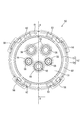
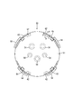
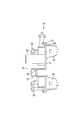
- FIG. 3 is an enlarged sectional view taken along the line cc of FIG. Perspective view of retainer with seal ring Retainer front view Plan view Rear view Dd line sectional view of FIG. Ee line enlarged sectional view of FIG. Ff line expanded sectional view of FIG. Rear view of seal ring Plan view Front view Gg sectional view of FIG. Hh expanded sectional view of FIG. Partial enlarged plan view according to i view of FIG.
- the vehicle-side connector VC of this embodiment is connected to a battery (not shown) mounted on an electric vehicle, a hybrid vehicle, or the like, and is fitted and connected to a charging connector (not shown) when charging the battery. It is like that.
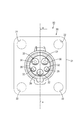
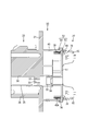
- the vehicle-side connector VC is a 5-pole connector, and as shown in FIGS. 1 to 4, an inlet housing 20 (hereinafter referred to as a housing 20) that houses a terminal fitting (not shown) and is mounted on a vehicle body, and terminals A retainer 50 is provided on the rear surface side of the housing 20 so as to prevent the metal fitting from coming off.
- the terminal fitting consists of two power terminals, one ground terminal, and two signal terminals, and may have different diameters depending on the type, but the basic structure is the same. It is. In the following description, the ground terminal is taken as an example.
- the terminal fitting is formed as a round bar-like forged product as a whole, and a small-diameter terminal connection portion, a flange portion, and a large-diameter wire connection portion are sequentially provided from the front side.
- the distal end side of the terminal connecting portion can be connected to a counterpart charging side terminal (not shown), and a cap (not shown) made of an insulating material is fitted to the distal end of the terminal connecting portion.
- a crimping hole (not shown) opened on the rear surface is formed on the rear side of the electric wire connecting portion.
- An unillustrated electric wire is subjected to a terminal treatment in which the end of the insulation coating has been cut (skinned) by a predetermined length, and the exposed end of the core wire is inserted into the above-described crimping hole and is crimped, whereby the end of the electric wire Is electrically connected to the wire connection portion of the terminal fitting.
- the housing 20 is made of synthetic resin, and as shown in FIGS. 1 and 4, a mounting plate 21 fixed to a panel constituting a vehicle body and a terminal housing chamber 30 in which terminal fittings are housed are formed and attached.
- the terminal accommodating part 25 provided by penetrating the board 21 in the front-rear direction, and the peripheral wall 40 formed so as to surround the outer periphery of the terminal accommodating part 25 from the back surface of the mounting plate 21 are provided.
- the mounting plate 21 is formed in a square shape, and mounting holes 22 are opened at four corners.
- a hood portion 26 is formed on the outer periphery of the terminal accommodating portion 25, and the front end side of the terminal accommodating portion 25 is integrally formed with the hood portion 26 so as to protrude from the front surface of the mounting plate 21 by a predetermined dimension.
- Five terminal accommodating chambers 30 are formed in the terminal accommodating portion 25, and are formed in the arrangement shown in FIG.
- the terminal housing chamber 30 may have different lengths and the like depending on the type of terminal fitting to be housed, but the basic structure is the same.
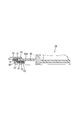
- FIG. 4 shows a terminal accommodating chamber 30 that accommodates a ground terminal.
- the terminal accommodating chamber 30 is generally formed by circular holes that are open on both front and rear surfaces, and the front side with the intermediate wall 32 interposed therebetween is a front accommodating chamber and the rear side is a rear accommodating chamber.
- a terminal insertion hole 33 is formed through the center of the intermediate wall 32. The terminal fitting is inserted into the rear receiving chamber of the terminal receiving chamber 30 from the rear, and after the terminal connecting portion is pushed through the terminal insertion hole 33, the insertion is stopped by the flange portion coming into contact with the rear surface of the intermediate wall 32. It has become. At this time, the tip end portion of the terminal connecting portion protrudes into the front housing chamber, and the flange portion and the position near the rear end of the wire connecting portion are accommodated in the rear housing chamber.
- a synthetic resin retainer 50 is mounted on the rear surface side of the housing 20 to prevent the terminal fittings from coming off.
- the peripheral wall 40 having a cylindrical shape with the rear surface opening is formed so as to surround the rear region from the rear end portion of the terminal accommodating portion 25. Is formed.
- a retainer 50 is attached to the rear opening 40A of the peripheral wall 40.
- the retainer 50 is formed in a cap shape in which a double cylinder portion 52 composed of an inner cylinder 53 and an outer cylinder 54 is formed on the outer periphery of the front surface of a circular substrate 51. Yes.
- the inner cylinder 53 in the double cylinder portion 52 is fitted with clearance inside the rear end of the peripheral wall 40, while the outer cylinder 54 is outside the rear end of the peripheral wall 40. It is designed to be fitted almost tightly.
- each locking sleeve 55 is disposed at a position corresponding to each terminal accommodating chamber 30 in the terminal accommodating portion 25 of the housing 20 and can be fitted into the rear accommodating chamber in the terminal accommodating chamber 30 almost tightly.
- the tips of the five locking sleeves 55 are connected to the intermediate wall in the rear housing chamber. It advances to a rear position with a predetermined interval of 32, and comes into contact with the terminal fitting that is stopped in front from the rear.
- a part of the terminal of the electric wire pulled out rearward from the electric wire connection part and the electric wire connection part from the flange part in a terminal metal fitting can be penetrated.
- the housing 20 is formed with a drainage structure for draining water hung on the front side of the housing 20 to the outside of the housing 20, and the retainer 50 described above constitutes a part thereof.
- the retainer 50 is configured such that a drainage structure is formed by mounting the rear surface opening 40A of the peripheral wall 40 in a watertight manner. Therefore, a rubber seal ring 70 is fitted to the outer peripheral surface of the inner cylinder 53 in the double cylinder portion 52 of the retainer 50 over the entire circumference.
- a lock structure of the retainer 50 four lock pieces 58 are formed at predetermined angular intervals on the front edge of the outer cylinder 54 in the double cylinder portion 52, as shown in FIGS.
- lock protrusions (not shown) that fit into the lock pieces 58 are formed on the outer peripheral surface of the peripheral wall 40 correspondingly.
- the seal ring 70 has a width (length in the axial direction) comparable to the protruding length of the inner cylinder 53, the outer peripheral surface of the inner cylinder 53, and the rear opening 40A of the peripheral wall 40.
- the ring is formed in a ring shape having a thickness that fits tightly into the clearance between the inner peripheral surface and the inner peripheral surface.
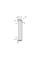
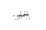
- two lips 71 extending around the entire periphery are formed at predetermined intervals in the axial direction.
- two cut grooves 72 are formed on the inner peripheral surface of the seal ring 70 over the entire circumference at positions corresponding to the inside of each lip 71. Thereby, the thickness of the seal ring 70 is made substantially constant in the axial direction.
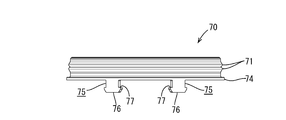
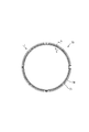
- a total of four retaining portions 75 are protruded from the rear surface of the seal ring 70.
- a short flange 74 is formed to rise over the entire circumference, and a retaining portion 75 is formed to protrude from the outer periphery of the flange 74.
- the formation positions of the retaining portions 75 are positions that are swung 25 degrees to the left and right across the center line.
- the retaining portion 75 is formed in a plate shape having substantially the same thickness as the seal ring 70, and a locking head portion 76 having a substantially trapezoidal shape as shown in FIG. It is formed so as to project laterally from the left and right side edges of 75.
- a rear edge 77 serving as a locking edge is perpendicular to the axis (center line) of the locking head 76.
- the locking head 76 has a so-called tapered shape that gradually becomes narrower toward the tip.
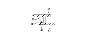
- the outer peripheral edge of the substrate 51 of the retainer 50 specifically, in the portion corresponding to the back wall 60 of the double cylinder portion 52, as shown in FIG.
- a fitting groove into which the flange 74 of the seal ring 70 fits. 61 is formed over the entire circumference, and four locking holes 62 through which the retaining portions 75 (basic end portions of equal width) can be inserted are formed in the inner surface of the fitting groove 61 correspondingly. Has been.
- the seal ring 70 is fitted to the outer periphery of the inner cylinder 53 in the double cylinder portion 52 of the retainer 50 in a rotational posture in which each retaining portion 75 corresponds to each locking hole 62, and the locking head 76 is halfway. And is inserted into the locking hole 62 while being slid in contact with the outer peripheral surface of the inner cylinder 53.
- the locking head 76 is pulled out to the back side of the locking hole 62 as shown in FIG. Bullet expansion and the rear edge 77 of the locking head 76 are locked to the right and left hole edges on the back side of the locking hole 62, thereby preventing the seal ring 70 from coming off.
- each arcuate mounting plates 65 are formed on the outer peripheral edge of the rear surface of the substrate 51 of the retainer 50 so as to attach a cover (not shown).
- the above-described locking holes 62 are all formed at the inner side of the mounting plate 65, the locking holes 62 are particularly formed on the side edges of the mounting plates 65 as shown in FIG. It is formed at a position close to. This is intended to make it easier for the locking hole 62 to be visually observed despite the mounting plate 65 being provided.
- each locking sleeve 55 is fitted to the rear end of the rear housing chamber in the corresponding terminal housing chamber 30 to be in a predetermined rotation posture.
- Each of the locking sleeves 55 is aligned, and the seal ring 70 is inserted between the outer peripheral surface of the inner cylinder 53 and the inner peripheral surface of the rear opening 40A of the peripheral wall 40 in the thickness direction. It is pushed in while inserting the rear end portion of the peripheral wall 40 into the double cylindrical portion 52 while being elastically compressed. As shown in FIGS.
- each lock piece 58 is locked to the lock protrusion (
- the retainer 50 is attached to the rear surface opening 40A of the peripheral wall 40 in a watertight manner and locked in the attached state (see FIG. 2).
- the vehicle side connector VC is assembled in the following procedure, for example. With respect to the retainer 50, a seal ring 70 is fitted on the outer periphery of the inner cylinder 53 in the double cylinder portion 52.
- the seal ring 70 is configured so that the retaining portions 75 projecting from the rear surface correspond to the respective locking holes 62 formed in the back wall 60 of the double tubular portion 52, and the inner tube
- the outer peripheral surface of the inner cylinder 53 is slid and pressed while the locking head 76 is elastically retracted from the middle and inserted into the locking hole 62. Since the locking head portion 76 of the retaining portion 75 is tapered, the operation of pushing into the locking hole 62 can be facilitated.
- the seal ring 70 is slidably mounted on the outer peripheral surface of the inner cylinder 53 while receiving a frictional resistance. However, since the thickness of the seal ring 70 is substantially constant in the axial direction, Buckling is avoided. Therefore, the seal ring 70 is attached relatively smoothly.
- the retainer 50 waiting in the rear is moved forward. After that, the retainer 50 is positioned by fitting each locking sleeve 55 into the corresponding rear receiving chamber of the terminal receiving chamber 30, causing each locking sleeve 55 to enter the rear receiving chamber, and the seal ring 70. It is pushed in while inserting the rear end portion of the peripheral wall 40 into the double cylindrical portion 52 while being elastically compressed in the thickness direction.
- the retainer 50 when the retainer 50 is pushed to a normal position where the rear end of the peripheral wall 40 hits the back wall 60 of the double cylindrical portion 52, the retainer 50 is provided in the retainer 50 as shown in FIG. 2.
- the lock piece 58 is elastically fitted to a lock protrusion (not shown) of the peripheral wall 40. As a result, the retainer 50 is attached in a watertight manner to the rear opening 40A of the peripheral wall 40 and is locked in the attached state.
- the retainer 50 is water-tightly attached to the rear opening 40 ⁇ / b> A of the peripheral wall 40 of the housing 20, so that a closed space is formed between the peripheral wall 40, the terminal accommodating portion 25, and the retainer 50.
- the five electric wires drawn out from the rear end of each locking sleeve 55 of the retainer 50 are bent downward, and then bundled together and extended downward while being accommodated in a cover (not shown). The assembly of the vehicle side connector VC is completed.
- the vehicle-side connector VC assembled as described above is inserted into an attachment hole opened in the panel from the inner surface side (back surface side), and is fixed to the panel by bolting the four corners of the attachment plate 21. At this time, the vehicle-side connector VC is attached in a rearward inclined posture in which the upper end is slightly inclined backward.
- the electric wires that extend downward as a group are passed through a corrugated tube or boots to be waterproofed and then connected to a battery mounted on the vehicle.
- the lid disposed on the front side of the housing 20 (terminal accommodating portion 25) of the vehicle side connector VC is opened, and then the charging connector connected to the external power source is the housing 20 (terminal accommodating) of the vehicle side connector VC. Part 25) and charged to the battery.
- the engaging head 76 is provided at the front end of the seal ring 70 at the portion where the seal ring 70 is fitted to the outer peripheral surface of the inner cylinder 53 in the double cylinder portion 52 of the retainer 50.
- four retaining portions 75 having protrusions are formed on the rear wall 60 of the double cylindrical portion 52, and locking holes 62 that can penetrate the retaining portions 75 are provided. The locking head 76 is locked from the rear, and the function of preventing the seal ring 70 from coming off is constructed.
- the seal ring 70 is prevented from being displaced from the normal mounting position, and the retainer 50 is attached to the rear opening 40A of the peripheral wall 40 of the housing 20. In this case, a reliable sealing function can be obtained. Further, by visually observing that the locking head portion 76 of the retaining portion 75 provided on the seal ring 70 passes through the back side of the locking hole 62, the seal ring 70 is mounted in the normal position. As a result, it is ensured that a proper sealing function is exhibited when the retainer 50 is mounted. Therefore, it is not necessary to provide a large inspection process for inspecting the presence or absence of leakage, and the connector assembly process can be simplified.
- the retaining portion 75 is formed in a plate shape so that the retaining head portion 76 is provided so as to protrude laterally from both side edges of the retaining portion 75, and therefore, the rear edge 77 of the retaining head portion 76.
- the seal ring 70 of the present embodiment has two lips 71 formed on the outer peripheral surface in order to improve the adhesion, while the inner peripheral surface has two lips 71 at positions corresponding to the inside of each lip 71.
- a slit groove 72 is formed over the entire circumference.
- the seal ring 70 is mounted while receiving frictional resistance against the outer peripheral surface of the inner cylinder 53 in the double cylinder portion 52 of the retainer 50.
- the seal ring 70 is mounted with a substantially constant thickness. Sometimes buckling is avoided, and as a result, the seal ring 70 can be mounted more smoothly.
- the locking head portion 76 of the retaining portion 75 provided in the retainer 50 is formed in a tapered shape, the operation of pushing the locking head portion 76 of the retaining portion 75 into the retaining hole 62 is facilitated. This is also useful for smoothly mounting the seal ring 70.
- the technology disclosed in this specification is not limited to the embodiments described with reference to the above description and drawings, and includes, for example, the following various aspects.
- the number and arrangement of the retaining portions 75 provided on the rear surface of the seal ring are not limited to those exemplified in the above-described embodiment, but are arbitrary. It is preferable.
- the number of the lips 71 formed on the outer peripheral surface of the seal ring is not limited to the two illustrated in the above embodiment, but may be one or a plurality of three or more. In that case, it is preferable that the number of the cut grooves 72 formed on the inner peripheral surface of the seal ring is the same as the number of the lips 71.
- the cut groove 72 on the inner peripheral surface of the seal ring is not necessarily required, and the cut groove 72 is not formed, or the inner peripheral lip is provided regardless of the position of the lip 71 on the outer peripheral surface. Such a thing may be included in the technical scope.
- the assembly procedure of the vehicle-side connector VC exemplified in the above embodiment is merely an example, and can be changed as appropriate, for example, by shifting the mounting timing of the seal ring 70 with respect to the retainer 50.
- the rear end opening of the locking sleeve 55 provided in the retainer may be sealed with a private chamber rubber stopper as necessary.
- a private chamber rubber stopper as necessary.
- the case where the electric wire drawn out to the rear surface side of the housing 20 is bent at a right angle and extended is exemplified, but the electric wire is extended along the axial direction toward the rear. May be.
- the technology disclosed in this specification is not limited to the vehicle-side connector, and is a waterproof structure for all connectors in a form in which a retainer for preventing the terminal metal fitting is attached to the rear surface opening of the housing in which the terminal metal fitting is accommodated. Can be widely applied.
- VC Vehicle side connector (connector) 20 ... Inlet housing (housing) DESCRIPTION OF SYMBOLS 30 ... Terminal accommodating chamber 40 ... Peripheral wall 40A ... Rear surface opening part 50 ... Retainer 53 ... Inner cylinder (fitting cylinder part) 55 ... Locking sleeve 60 ... Back wall (periphery of retainer 50) 62 ... Locking hole 70 ... Seal ring 71 ... Lip 72 ... Cut groove 75 ... Stopping part 76 ... Locking head 77 ... Rear edge of the locking head 76
Landscapes
- Connector Housings Or Holding Contact Members (AREA)
Abstract
L'invention concerne un connecteur côté véhicule VC qui comprend : un boîtier 20 qui est pourvu d'une chambre de logement de borne 30 ; un dispositif de retenue 50 qui est installé de façon à recouvrir une partie d'ouverture de surface arrière 40A du boîtier 20 ; une partie de cylindre d'ajustement 53 qui est disposée au niveau d'une surface avant du dispositif de retenue 50 et qui peut être ajustée, avec un jeu, dans la partie d'ouverture de surface arrière 40A du boîtier 20 ; et une bague d'étanchéité 70 qui est installée sur une surface circonférentielle externe de la partie de cylindre d'ajustement 53 et qui se contracte élastiquement entre ladite surface circonférentielle externe et une surface circonférentielle interne de la partie d'ouverture de surface arrière 40A. Une partie de retenue 75 qui comporte une partie de tête de mise en prise 76 à sa pointe est formée de façon à faire saillie à partir d'une surface arrière de la bague d'étanchéité 70. Un trou de mise en prise 62 à travers lequel peut être passée la partie de retenue 75 est ménagé au niveau d'une partie de bord circonférentiel du dispositif de retenue 50, et la partie de tête de mise en prise 76 vient en prise avec une partie de bord de trou du trou de mise en prise 62 à partir de l'arrière.
Priority Applications (2)
| Application Number | Priority Date | Filing Date | Title |
|---|---|---|---|
| CN201780022684.7A CN109075495B (zh) | 2016-04-12 | 2017-03-22 | 连接器 |
| US16/088,559 US10355388B2 (en) | 2016-04-12 | 2017-03-22 | Connector |
Applications Claiming Priority (2)
| Application Number | Priority Date | Filing Date | Title |
|---|---|---|---|
| JP2016-079474 | 2016-04-12 | ||
| JP2016079474A JP6607135B2 (ja) | 2016-04-12 | 2016-04-12 | コネクタ |
Publications (1)
| Publication Number | Publication Date |
|---|---|
| WO2017179376A1 true WO2017179376A1 (fr) | 2017-10-19 |
Family
ID=60042083
Family Applications (1)
| Application Number | Title | Priority Date | Filing Date |
|---|---|---|---|
| PCT/JP2017/011365 Ceased WO2017179376A1 (fr) | 2016-04-12 | 2017-03-22 | Connecteur |
Country Status (4)
| Country | Link |
|---|---|
| US (1) | US10355388B2 (fr) |
| JP (1) | JP6607135B2 (fr) |
| CN (1) | CN109075495B (fr) |
| WO (1) | WO2017179376A1 (fr) |
Families Citing this family (5)
| Publication number | Priority date | Publication date | Assignee | Title |
|---|---|---|---|---|
| JP2019063490A (ja) * | 2018-04-23 | 2019-04-25 | 株式会社コロプラ | ゲームプログラム、方法、及び情報処理装置 |
| TWM568526U (zh) * | 2018-05-31 | 2018-10-11 | 正崴精密工業股份有限公司 | 電動車充電連接器總成 |
| JP7230711B2 (ja) * | 2019-06-28 | 2023-03-01 | 住友電装株式会社 | コネクタ |
| CN210430179U (zh) * | 2019-08-15 | 2020-04-28 | 东莞富强电子有限公司 | 电动车插座连接器装置 |
| JP7694420B2 (ja) * | 2022-02-25 | 2025-06-18 | 住友電装株式会社 | 充電インレット |
Citations (5)
| Publication number | Priority date | Publication date | Assignee | Title |
|---|---|---|---|---|
| JPH09129303A (ja) * | 1995-11-07 | 1997-05-16 | Yazaki Corp | 防水コネクタ |
| JP2010080106A (ja) * | 2008-09-24 | 2010-04-08 | Sumitomo Wiring Syst Ltd | コネクタ |
| JP2014135194A (ja) * | 2013-01-10 | 2014-07-24 | Sumitomo Wiring Syst Ltd | 防水コネクタ |
| JP2014229420A (ja) * | 2013-05-21 | 2014-12-08 | 株式会社オートネットワーク技術研究所 | 防水コネクタ |
| JP2016035804A (ja) * | 2014-08-01 | 2016-03-17 | 住友電装株式会社 | 車両側コネクタ |
Family Cites Families (16)
| Publication number | Priority date | Publication date | Assignee | Title |
|---|---|---|---|---|
| JPH07101621B2 (ja) * | 1987-06-16 | 1995-11-01 | 住友電装株式会社 | コネクタ |
| JP3570481B2 (ja) * | 1998-05-28 | 2004-09-29 | 住友電装株式会社 | パネル取り付けコネクタ |
| JP3968638B2 (ja) * | 2001-03-02 | 2007-08-29 | 住友電装株式会社 | コネクタ |
| JP2002343503A (ja) * | 2001-05-17 | 2002-11-29 | Yazaki Corp | 多極コネクタ |
| JP3767460B2 (ja) * | 2001-11-05 | 2006-04-19 | 住友電装株式会社 | 防水コネクタ |
| JP2006059595A (ja) * | 2004-08-18 | 2006-03-02 | Sumitomo Wiring Syst Ltd | 防水コネクタ |
| JP2006156081A (ja) | 2004-11-29 | 2006-06-15 | Sumitomo Wiring Syst Ltd | 防水コネクタ |
| BRPI0801086A2 (pt) * | 2008-03-31 | 2009-11-17 | Whirlpool Sa | arranjo de montagem de cabo de alimentação elétrica em compressor de refrigeração |
| JP5123144B2 (ja) * | 2008-11-21 | 2013-01-16 | 矢崎総業株式会社 | 充電用コネクタ |
| JP5368904B2 (ja) | 2009-07-28 | 2013-12-18 | トヨタ自動車株式会社 | 車両用心電計測装置 |
| US8771014B2 (en) * | 2010-02-04 | 2014-07-08 | Yazaki Corporation | Connector housing with mat seal |
| JP2012221785A (ja) * | 2011-04-11 | 2012-11-12 | Sumitomo Wiring Syst Ltd | コネクタ |
| JP5733168B2 (ja) * | 2011-11-18 | 2015-06-10 | 住友電装株式会社 | 防水コネクタ |
| CN104218378B (zh) * | 2013-05-29 | 2017-03-22 | 中航光电科技股份有限公司 | 快锁密封式连接器组件及其插头和插座 |
| JP5747950B2 (ja) * | 2013-06-20 | 2015-07-15 | Smk株式会社 | コネクタ |
| JP2015162278A (ja) * | 2014-02-26 | 2015-09-07 | 住友電装株式会社 | サービスカバー |
-
2016
- 2016-04-12 JP JP2016079474A patent/JP6607135B2/ja active Active
-
2017
- 2017-03-22 CN CN201780022684.7A patent/CN109075495B/zh active Active
- 2017-03-22 WO PCT/JP2017/011365 patent/WO2017179376A1/fr not_active Ceased
- 2017-03-22 US US16/088,559 patent/US10355388B2/en active Active
Patent Citations (5)
| Publication number | Priority date | Publication date | Assignee | Title |
|---|---|---|---|---|
| JPH09129303A (ja) * | 1995-11-07 | 1997-05-16 | Yazaki Corp | 防水コネクタ |
| JP2010080106A (ja) * | 2008-09-24 | 2010-04-08 | Sumitomo Wiring Syst Ltd | コネクタ |
| JP2014135194A (ja) * | 2013-01-10 | 2014-07-24 | Sumitomo Wiring Syst Ltd | 防水コネクタ |
| JP2014229420A (ja) * | 2013-05-21 | 2014-12-08 | 株式会社オートネットワーク技術研究所 | 防水コネクタ |
| JP2016035804A (ja) * | 2014-08-01 | 2016-03-17 | 住友電装株式会社 | 車両側コネクタ |
Also Published As
| Publication number | Publication date |
|---|---|
| JP6607135B2 (ja) | 2019-11-20 |
| CN109075495A (zh) | 2018-12-21 |
| US10355388B2 (en) | 2019-07-16 |
| CN109075495B (zh) | 2020-10-20 |
| US20190109400A1 (en) | 2019-04-11 |
| JP2017191669A (ja) | 2017-10-19 |
Similar Documents
| Publication | Publication Date | Title |
|---|---|---|
| JP5310010B2 (ja) | シールドコネクタ | |
| JP5417954B2 (ja) | 防水コネクタ | |
| US9385516B2 (en) | Connector | |
| JP5854302B2 (ja) | 車両側コネクタ | |
| JP6607135B2 (ja) | コネクタ | |
| JP5072781B2 (ja) | コネクタ | |
| US9106066B2 (en) | Wire fixing member | |
| JP5704025B2 (ja) | ジョイントコネクタ | |
| JP5704021B2 (ja) | ゴム栓及び防水コネクタ | |
| JP2016012422A (ja) | コネクタ | |
| US9022804B2 (en) | Waterproof plug | |
| JP2018133278A (ja) | 充電インレット | |
| JP5375741B2 (ja) | コネクタ | |
| US10622757B2 (en) | Connector with rubber cover | |
| CN105981234A (zh) | 连接器 | |
| JP6048327B2 (ja) | コネクタ | |
| JP2005005035A (ja) | 防水コネクタ用ゴム栓 | |
| JP5440437B2 (ja) | 電線の端末構造 | |
| WO2015166928A1 (fr) | Structure imperméabilisante pour connecteur | |
| JP2016012421A (ja) | コネクタのシール構造 | |
| JP2017191643A (ja) | 車両側コネクタ | |
| JP5985409B2 (ja) | コネクタ | |
| JP2012069375A (ja) | 防水コネクタ | |
| JP2013143241A (ja) | コネクタ | |
| JP5772580B2 (ja) | 電線固定部材 |
Legal Events
| Date | Code | Title | Description |
|---|---|---|---|
| NENP | Non-entry into the national phase |
Ref country code: DE |
|
| 121 | Ep: the epo has been informed by wipo that ep was designated in this application |
Ref document number: 17782194 Country of ref document: EP Kind code of ref document: A1 |
|
| 122 | Ep: pct application non-entry in european phase |
Ref document number: 17782194 Country of ref document: EP Kind code of ref document: A1 |