WO2017179399A1 - Échangeur de chaleur - Google Patents
Échangeur de chaleur Download PDFInfo
- Publication number
- WO2017179399A1 WO2017179399A1 PCT/JP2017/012036 JP2017012036W WO2017179399A1 WO 2017179399 A1 WO2017179399 A1 WO 2017179399A1 JP 2017012036 W JP2017012036 W JP 2017012036W WO 2017179399 A1 WO2017179399 A1 WO 2017179399A1
- Authority
- WO
- WIPO (PCT)
- Prior art keywords
- fin
- heat exchanger
- fins
- exchanger according
- fin collar
- Prior art date
- Legal status (The legal status is an assumption and is not a legal conclusion. Google has not performed a legal analysis and makes no representation as to the accuracy of the status listed.)
- Ceased
Links
Images












Classifications
-
- F—MECHANICAL ENGINEERING; LIGHTING; HEATING; WEAPONS; BLASTING
- F28—HEAT EXCHANGE IN GENERAL
- F28D—HEAT-EXCHANGE APPARATUS, NOT PROVIDED FOR IN ANOTHER SUBCLASS, IN WHICH THE HEAT-EXCHANGE MEDIA DO NOT COME INTO DIRECT CONTACT
- F28D1/00—Heat-exchange apparatus having stationary conduit assemblies for one heat-exchange medium only, the media being in contact with different sides of the conduit wall, in which the other heat-exchange medium is a large body of fluid, e.g. domestic or motor car radiators
- F28D1/02—Heat-exchange apparatus having stationary conduit assemblies for one heat-exchange medium only, the media being in contact with different sides of the conduit wall, in which the other heat-exchange medium is a large body of fluid, e.g. domestic or motor car radiators with heat-exchange conduits immersed in the body of fluid
- F28D1/04—Heat-exchange apparatus having stationary conduit assemblies for one heat-exchange medium only, the media being in contact with different sides of the conduit wall, in which the other heat-exchange medium is a large body of fluid, e.g. domestic or motor car radiators with heat-exchange conduits immersed in the body of fluid with tubular conduits
-
- F—MECHANICAL ENGINEERING; LIGHTING; HEATING; WEAPONS; BLASTING
- F28—HEAT EXCHANGE IN GENERAL
- F28F—DETAILS OF HEAT-EXCHANGE AND HEAT-TRANSFER APPARATUS, OF GENERAL APPLICATION
- F28F1/00—Tubular elements; Assemblies of tubular elements
- F28F1/02—Tubular elements of cross-section which is non-circular
- F28F1/022—Tubular elements of cross-section which is non-circular with multiple channels
-
- F—MECHANICAL ENGINEERING; LIGHTING; HEATING; WEAPONS; BLASTING
- F28—HEAT EXCHANGE IN GENERAL
- F28F—DETAILS OF HEAT-EXCHANGE AND HEAT-TRANSFER APPARATUS, OF GENERAL APPLICATION
- F28F1/00—Tubular elements; Assemblies of tubular elements
- F28F1/10—Tubular elements and assemblies thereof with means for increasing heat-transfer area, e.g. with fins, with projections, with recesses
- F28F1/12—Tubular elements and assemblies thereof with means for increasing heat-transfer area, e.g. with fins, with projections, with recesses the means being only outside the tubular element
- F28F1/24—Tubular elements and assemblies thereof with means for increasing heat-transfer area, e.g. with fins, with projections, with recesses the means being only outside the tubular element and extending transversely
- F28F1/26—Tubular elements and assemblies thereof with means for increasing heat-transfer area, e.g. with fins, with projections, with recesses the means being only outside the tubular element and extending transversely the means being integral with the element
- F28F1/28—Tubular elements and assemblies thereof with means for increasing heat-transfer area, e.g. with fins, with projections, with recesses the means being only outside the tubular element and extending transversely the means being integral with the element the element being built-up from finned sections
-
- F—MECHANICAL ENGINEERING; LIGHTING; HEATING; WEAPONS; BLASTING
- F28—HEAT EXCHANGE IN GENERAL
- F28F—DETAILS OF HEAT-EXCHANGE AND HEAT-TRANSFER APPARATUS, OF GENERAL APPLICATION
- F28F1/00—Tubular elements; Assemblies of tubular elements
- F28F1/10—Tubular elements and assemblies thereof with means for increasing heat-transfer area, e.g. with fins, with projections, with recesses
- F28F1/12—Tubular elements and assemblies thereof with means for increasing heat-transfer area, e.g. with fins, with projections, with recesses the means being only outside the tubular element
- F28F1/24—Tubular elements and assemblies thereof with means for increasing heat-transfer area, e.g. with fins, with projections, with recesses the means being only outside the tubular element and extending transversely
- F28F1/32—Tubular elements and assemblies thereof with means for increasing heat-transfer area, e.g. with fins, with projections, with recesses the means being only outside the tubular element and extending transversely the means having portions engaging further tubular elements
-
- F—MECHANICAL ENGINEERING; LIGHTING; HEATING; WEAPONS; BLASTING
- F28—HEAT EXCHANGE IN GENERAL
- F28F—DETAILS OF HEAT-EXCHANGE AND HEAT-TRANSFER APPARATUS, OF GENERAL APPLICATION
- F28F1/00—Tubular elements; Assemblies of tubular elements
- F28F1/10—Tubular elements and assemblies thereof with means for increasing heat-transfer area, e.g. with fins, with projections, with recesses
- F28F1/12—Tubular elements and assemblies thereof with means for increasing heat-transfer area, e.g. with fins, with projections, with recesses the means being only outside the tubular element
- F28F1/24—Tubular elements and assemblies thereof with means for increasing heat-transfer area, e.g. with fins, with projections, with recesses the means being only outside the tubular element and extending transversely
- F28F1/32—Tubular elements and assemblies thereof with means for increasing heat-transfer area, e.g. with fins, with projections, with recesses the means being only outside the tubular element and extending transversely the means having portions engaging further tubular elements
- F28F1/325—Fins with openings
-
- F—MECHANICAL ENGINEERING; LIGHTING; HEATING; WEAPONS; BLASTING
- F28—HEAT EXCHANGE IN GENERAL
- F28F—DETAILS OF HEAT-EXCHANGE AND HEAT-TRANSFER APPARATUS, OF GENERAL APPLICATION
- F28F1/00—Tubular elements; Assemblies of tubular elements
- F28F1/10—Tubular elements and assemblies thereof with means for increasing heat-transfer area, e.g. with fins, with projections, with recesses
- F28F1/40—Tubular elements and assemblies thereof with means for increasing heat-transfer area, e.g. with fins, with projections, with recesses the means being only inside the tubular element
-
- F—MECHANICAL ENGINEERING; LIGHTING; HEATING; WEAPONS; BLASTING
- F28—HEAT EXCHANGE IN GENERAL
- F28F—DETAILS OF HEAT-EXCHANGE AND HEAT-TRANSFER APPARATUS, OF GENERAL APPLICATION
- F28F13/00—Arrangements for modifying heat-transfer, e.g. increasing, decreasing
- F28F13/18—Arrangements for modifying heat-transfer, e.g. increasing, decreasing by applying coatings, e.g. radiation-absorbing, radiation-reflecting; by surface treatment, e.g. polishing
- F28F13/185—Heat-exchange surfaces provided with microstructures or with porous coatings
-
- F—MECHANICAL ENGINEERING; LIGHTING; HEATING; WEAPONS; BLASTING
- F28—HEAT EXCHANGE IN GENERAL
- F28F—DETAILS OF HEAT-EXCHANGE AND HEAT-TRANSFER APPARATUS, OF GENERAL APPLICATION
- F28F13/00—Arrangements for modifying heat-transfer, e.g. increasing, decreasing
- F28F13/18—Arrangements for modifying heat-transfer, e.g. increasing, decreasing by applying coatings, e.g. radiation-absorbing, radiation-reflecting; by surface treatment, e.g. polishing
- F28F13/185—Heat-exchange surfaces provided with microstructures or with porous coatings
- F28F13/187—Heat-exchange surfaces provided with microstructures or with porous coatings especially adapted for evaporator surfaces or condenser surfaces, e.g. with nucleation sites
-
- F—MECHANICAL ENGINEERING; LIGHTING; HEATING; WEAPONS; BLASTING
- F28—HEAT EXCHANGE IN GENERAL
- F28F—DETAILS OF HEAT-EXCHANGE AND HEAT-TRANSFER APPARATUS, OF GENERAL APPLICATION
- F28F19/00—Preventing the formation of deposits or corrosion, e.g. by using filters or scrapers
- F28F19/02—Preventing the formation of deposits or corrosion, e.g. by using filters or scrapers by using coatings, e.g. vitreous or enamel coatings
- F28F19/04—Preventing the formation of deposits or corrosion, e.g. by using filters or scrapers by using coatings, e.g. vitreous or enamel coatings of rubber; of plastics material; of varnish
-
- F—MECHANICAL ENGINEERING; LIGHTING; HEATING; WEAPONS; BLASTING
- F28—HEAT EXCHANGE IN GENERAL
- F28F—DETAILS OF HEAT-EXCHANGE AND HEAT-TRANSFER APPARATUS, OF GENERAL APPLICATION
- F28F19/00—Preventing the formation of deposits or corrosion, e.g. by using filters or scrapers
- F28F19/02—Preventing the formation of deposits or corrosion, e.g. by using filters or scrapers by using coatings, e.g. vitreous or enamel coatings
- F28F19/06—Preventing the formation of deposits or corrosion, e.g. by using filters or scrapers by using coatings, e.g. vitreous or enamel coatings of metal
-
- F—MECHANICAL ENGINEERING; LIGHTING; HEATING; WEAPONS; BLASTING
- F28—HEAT EXCHANGE IN GENERAL
- F28F—DETAILS OF HEAT-EXCHANGE AND HEAT-TRANSFER APPARATUS, OF GENERAL APPLICATION
- F28F3/00—Plate-like or laminated elements; Assemblies of plate-like or laminated elements
- F28F3/02—Elements or assemblies thereof with means for increasing heat-transfer area, e.g. with fins, with recesses, with corrugations
- F28F3/022—Elements or assemblies thereof with means for increasing heat-transfer area, e.g. with fins, with recesses, with corrugations the means being wires or pins
-
- F—MECHANICAL ENGINEERING; LIGHTING; HEATING; WEAPONS; BLASTING
- F28—HEAT EXCHANGE IN GENERAL
- F28F—DETAILS OF HEAT-EXCHANGE AND HEAT-TRANSFER APPARATUS, OF GENERAL APPLICATION
- F28F3/00—Plate-like or laminated elements; Assemblies of plate-like or laminated elements
- F28F3/02—Elements or assemblies thereof with means for increasing heat-transfer area, e.g. with fins, with recesses, with corrugations
- F28F3/04—Elements or assemblies thereof with means for increasing heat-transfer area, e.g. with fins, with recesses, with corrugations the means being integral with the element
-
- F—MECHANICAL ENGINEERING; LIGHTING; HEATING; WEAPONS; BLASTING
- F28—HEAT EXCHANGE IN GENERAL
- F28F—DETAILS OF HEAT-EXCHANGE AND HEAT-TRANSFER APPARATUS, OF GENERAL APPLICATION
- F28F2245/00—Coatings; Surface treatments
- F28F2245/04—Coatings; Surface treatments hydrophobic
Definitions
- the present invention relates to a heat exchanger, and more particularly to a plate fin type heat exchanger used in an air conditioner.
- a conventional heat exchanger includes, for example, a plurality of plate-shaped fins provided with a plurality of fin collars as in Patent Document 1, and a plurality of cylindrical fin collars have a plurality of hole centers so that the hole centers coincide with each other. Fins are stacked. The fin collars connected to each other are joined and sealed with a resin to form a plurality of liquid flow pipes and fin cores.
- the liquid passage tube is anticorrosive on the surface by a resin film formed on the inner peripheral surface.
- the thickness of the resin film formed on the inner peripheral surface of the liquid flow pipe is thin, defects such as scratches and pinholes generated in the resin film, the diameter of the resin film itself Peeling easily due to deterioration.
- a defect or peeling of the resin film occurs, corrosion of the fins proceeds and the heat exchange performance deteriorates.
- a thin resin film has insufficient strength, and it breaks due to bending, twisting, or shearing of a joint that is received when the heat exchanger is installed in a casing or transported.
- the resin film is made thick in order to improve the corrosion resistance, another problem arises that the resin film becomes a thermal resistance and the heat exchange performance is lowered.
- a fluid with a relatively high viscosity such as water or antifreeze is often passed through the liquid flow pipe.
- the liquid flow pipe is configured with a small diameter for high heat transfer, the flow of the liquid flow pipe is a layer. There was a problem that the heat exchange performance deteriorates due to fluidization.
- the present invention has been made to solve the above-described problems, and provides a heat exchanger capable of ensuring both heat exchange performance and reliability against corrosion, and the flow in the liquid flow pipe.
- the purpose of the heat exchanger is to obtain high heat exchange performance even in the case of laminar flow.
- the heat exchanger according to the present invention is arranged on a plurality of flat fins, an opening provided in each of the plurality of fins, and an outer peripheral side of the opening, and is larger than an outer diameter of the opening.
- a cylindrical member having an inner diameter, and the plurality of fins are stacked via the cylindrical member, and the opening and the cylindrical member form a liquid passage tube. It protrudes inward from the cylindrical member.
- the heat exchanger since the fins protruding inward from the cylindrical member are in direct contact with the heat medium, the heat exchange efficiency can be improved. Moreover, since the cylindrical member is provided and laminated on the outer peripheral side of the fin opening, the strength can be increased without increasing the thickness of the resin film as in the conventional case. Moreover, even if corrosion occurs, it is difficult to corrode in the surface direction of the fins, and a decrease in sealing performance is suppressed.
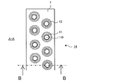
- FIG. 2 is a schematic view of fins when the heat exchanger according to Embodiment 1 is viewed from the AA direction in FIG. 1.
- FIG. 3 is a schematic view of the heat exchanger according to Embodiment 1 as viewed from the BB direction in FIG. 2.
- 6 is a schematic diagram illustrating fins of a heat exchanger according to Modification 1 of Embodiment 1.
- FIG. It is a schematic diagram explaining the fin collar of the heat exchanger which concerns on the modification of Embodiment 1.
- FIG. It is a schematic diagram which shows the cross section of the fin collar of the heat exchanger which concerns on Embodiment 2.
- FIG. 6 is a top view of the periphery of a fin collar of a heat exchanger according to Embodiment 4. 6 is a top view of a protrusion of a heat exchanger according to Embodiment 4.
- FIG. 10 is a schematic diagram showing a cross section around a fin collar of a heat exchanger according to Modification 1 of Embodiment 4.
- FIG. 17 is a perspective view of the fin collar of FIG. 16.
- FIG. 18 is a perspective view of a fin collar formed on a fin adjacent to the fin of FIG. 17.
- FIG. 20 is a perspective view of the fin collar of FIG. 19. It is a perspective view of the fin collar formed in the fin adjacent to the fin of FIG. It is a schematic diagram explaining the fin collar of the heat exchanger which concerns on Embodiment 6.
- FIG. 10 is a schematic diagram for explaining a fin collar of a heat exchanger according to a modification of the sixth embodiment. It is the schematic diagram seen from the flow direction of the liquid pipe of the fin collar of FIG.
- FIG. 26 is a perspective view of the fin collar of FIG. 25. It is a schematic diagram explaining the fin collar of the heat exchanger which concerns on the modification 2 of Embodiment 6.
- FIG. It is the schematic diagram seen from the flow direction of the liquid pipe through the fin collar of FIG. It is a perspective view of the fin collar of FIG.
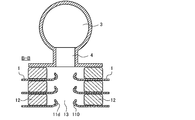
- FIG. 1 is a perspective view showing an appearance of a heat exchanger 10 according to the first embodiment.
- FIG. 1 the flow direction of the air WF and the flow direction of the water RF that is the heat transfer medium are indicated by arrows.
- FIG. 2 is a schematic diagram of the fin 1 when the heat exchanger 10 according to the first embodiment is viewed from the AA direction in FIG.
- FIG. 3 is a schematic view of the heat exchanger 10 according to Embodiment 1 as viewed from the BB direction of FIG.
- FIG. 3 although the structure of the upstream of the flow of the air WF is shown, since the structure of the downstream is also the same structure, illustration is abbreviate
- the heat exchanger 10 includes a plurality of laminated fins 1, a fin collar 11, and a resin member 12.
- Each of the plurality of fins 1 is a metal member such as aluminum having a flat plate shape, and the plurality of fins 1 are stacked in a direction orthogonal to the air flow direction. That is, each of the plurality of fins 1 is arranged in parallel with an interval.
- a plurality of fin collars 11 protruding in the stacking direction from a plurality of openings 110 formed in the fin 1 are provided on one surface of each fin 1.
- the plurality of fins 1 are stacked with the centers of the plurality of fin collars 11 aligned with a resin member 12 interposed therebetween.
- the laminated fin collar 11 and the resin member 12 form a liquid flow pipe 13 in the lamination direction of the plurality of fins 1.
- the resin member 12 is an example of a cylindrical member of the present invention. In the following description, the surface of the fin 1 on the side where the fin collar 11 protrudes is defined as the surface.
- the fin collar 11 has a cylindrical shape and is formed so as to protrude in the stacking direction of the plurality of fins 1, which is perpendicular to the surface of the fins 1, for example, by drawing.
- the fin collars 11 are arranged in multiple stages in the flow direction of the air WF orthogonal to the stacking direction of the fins 1, that is, in the row direction, for example, in two rows and in the vertical direction of the air WF flow direction, that is, in the step direction. , In a staggered arrangement.
- the resin member 12 has a cylindrical shape having an inner diameter larger than the outer diameter of the fin collar 11, and is disposed on the outer peripheral side of the fin collar 11 so as to surround the fin collar 11.
- the inner diameter of the resin member 12 is larger than the outer diameter of the fin collar 11, and the central axis of the resin member 12 and the central axis of the fin collar 11 coincide.
- the inner diameter of the resin member 12 may be substantially the same as the outer diameter of the fin collar 11, and in that case, the fin collar 11 is fitted to the resin member 12, and the resin member 12 is directed toward the inner surface of the fin 1. It is prevented from slipping.
- the outer peripheral surface of the resin member 12 and the inner peripheral surface of the fin collar 11 may be partially bonded to improve the strength against the in-plane force of the fin 1.
- the fin collar 11 is an example of the second fin of the present invention.
- the resin members 12 are inserted between the fins 1, and the fins 11 are connected and stacked via the resin members 12 so that the centers of the fin collars 11 provided on the fins 1 coincide with each other.
- a liquid passage 13 is formed by the fin collars 11 connected to each other and the resin member 12 that is in close contact with the fins 1 between the laminated fins 1 on the outer peripheral surface of the fin collars 11.
- the resin member 12 has an inner diameter larger than the outer diameter of the opening 110 where the fin collar 11 is provided, and the fin collar 11 protrudes inward from the resin member 12.
- the fin collar 11 is formed such that the height in the laminating direction is smaller than the height in the laminating direction of the resin member 12, and a gap formed between the end of the fin collar 11 and the back surface of the adjacent fin 1.
- the heat transfer medium of the fluid is exchanged via.
- an inlet header 2 provided on the downstream side of the air WF flow and an outlet header 3 provided on the downstream side of the air WF flow via a plurality of connection pipes 4.
- the outlet header 3 is connected to the resin member 12 disposed on the fin 1 at one end of the fins 1 to be laminated through the flanges of the plurality of connecting pipes 4 branched from the outlet header 3.
- the inlet header 2 is also connected to the resin member 12 of the fin 1 arranged at one end by the same configuration as the outlet header 3.
- the inlet header 2 and the outlet header 3 are connected to the liquid flow pipe 13 by the resin member 12 to which each is connected.
- the inlet header 2 and the outlet header 3 connect the liquid passage 13 extending from the inlet header 2 and the liquid passage 13 extending toward the outlet header 3 at the other end of the plurality of fins 1 to be stacked. They are connected by a U-shaped tube (not shown).
- the heat transfer medium is heated by heat exchange in the outdoor unit and flows into the indoor unit as hot water RF.
- the hot water RF flows in from the inlet header 2 of the heat exchanger 10 accommodated in the indoor unit, and flows through the liquid passage pipes 13 positioned on the downstream side of the air WF via the connection pipes 4.
- the hot water RF that has flowed through the respective flow pipes 13 on the downstream side of the air WF flows into the respective liquid flow pipes 13 positioned on the upstream side of the air WF via U-shaped pipes.
- the hot water RF that has flowed through the liquid passages 13 on the upstream side of the air WF joins and flows through the outlet header 3 via the connection pipes 4 and flows out toward the outdoor unit.
- the heat transfer medium In the cooling operation of the air conditioner, the heat transfer medium is cooled by heat exchange in the outdoor unit, flows into the indoor unit as cold water RF, and flows through the heat exchanger 10.
- the flow of the cold water RF in the heat exchanger 10 is the same as the flow during the heating operation.
- the indoor air WF is sucked by the blower of the indoor unit, and blown into the room in the flow direction of the air WF via the heat exchanger 10.
- the air WF sucked by the blower flows into the fin core 14 between the fins 1 adjacent to each other in the stacking direction from the direction orthogonal to the stacking direction of the fins 1.
- the air WF exchanges heat with the hot water RF in each flow-through pipe 13 located on the windward side, and exchanges heat with the hot water RF in each liquid-flow pipe 13 located on the leeward side to become warm air. It flows out into the room.
- the air WF that has become the cold air is sent into the room by the cold water RF that flows in the liquid passing pipes 13 on the leeward side and the windward side.
- the manufacturing method of the heat exchanger 10 In manufacturing the heat exchanger 10, first, the resin member 12 is arranged around the fin collar 11 provided on the first fin 1. Next, the second fin 1 is laminated on the first fin 1, and the resin member 12 disposed on the first fin 1 and the back surface of the second fin 1 are bonded with an adhesive. , Seal. At this time, the center of the fin collar 11 of the first fin 1 and the center of the second fin collar 11 are matched. Then, the resin member 12 is arranged around the fin collar 11 provided on the second fin 1. Next, the third fin 1 is laminated on the second fin 1, and the resin member 12 disposed on the second fin 1 and the back surface of the third fin 1 are bonded with an adhesive. , Seal.
- the center of the fin collar 11 of the second fin 1 and the third fin collar 11 are matched.
- the fourth and subsequent sheets are laminated in the same manner, and the heat exchanger 10 in which the liquid passage 13 is formed by the fin collars 11 of the plurality of laminated fins 1 is obtained.
- a plurality of liquid flow pipes 13 are formed by the laminated fins 1 and sealed in two rows in the row direction and in the step direction of each row by the resin member 12.
- the resin film on the inner surface of the fin collar is formed thick in order to increase the strength and corrosion resistance, a decrease in heat exchange performance due to an increase in thermal resistance is inevitable.
- the liquid passage tube 13 is sealed by the resin member 12 disposed outside the fin collar 11. For this reason, it is possible to achieve both heat exchange performance, strength and reliability against corrosion due to the fin 1 protruding inward directly contacting the heat medium. Even if corrosion occurs, it is difficult to corrode in the surface direction of the fin, and the deterioration of the sealing performance is suppressed.
- the fin 1 made of aluminum is described.
- the surface of the fin 1 can be provided with a base material layer that has a higher ionization tendency and is more easily corroded than the material of the fin 1.
- the fin 1 is made of aluminum, it is possible to prevent the corrosion generated in the fin 1 from proceeding toward the surface of the fin 1 by providing a layer that is more easily corroded than aluminum, such as zinc.
- FIG. 4 is a schematic diagram for explaining the fins 1 of the heat exchanger 10 according to the first modification of the first embodiment.
- FIG. 4 is a diagram corresponding to FIG. 3 shown in the above description.
- the resin member 12 is arranged around the opening 110, and the cylindrical fin collar 11 that protrudes in the stacking direction. Is not formed.
- the resin member 12 and the opening 110 can simplify the manufacturing process as well as the improvement of the heat exchange performance and the securing of the strength and the reliability against the corrosion as in the first embodiment.
- FIG. 5 is a schematic diagram illustrating the fin collar 11a of the heat exchanger 10 according to the modification of the first embodiment.
- FIG. 5 corresponds to FIG. 3 shown in the above description.
- the fin collar 11 a of the heat exchanger 10 according to the modification of the first embodiment has an outer diameter that matches the inner diameter of the resin member 12, and the resin member 12 fits into the fin collar 11.
- the number of arrangements of the liquid flow pipes 13 in the row direction and the step direction is not limited to the number shown in the first embodiment, and may be any number.
- the air WF and the water RF may be exchanged in a pseudo parallel flow by inverting the flow of the air WF without exchanging heat in the pseudo counter flow.
- the cylindrical resin member 12 having a circular cross section is described as an example.
- the resin member 12 is not limited to a circular shape, and may be a polygonal cross sectional shape such as a triangle or a quadrangle.
- the interface between the fin 1 and the resin member 12 inserted between the fins 1 may be joined with an adhesive or the like.
- the adhesive member is formed in a ring shape and is heated by a temperature of about 100 to 300 ° C. It may be joined by melting and solidifying.
- a reactive foam material such as urethane foam applied around the fin collar 11, an adhesive mixed with a thermally expandable microcapsule, etc. Can also be applied.
- the fins 1 are joined by foaming or expanding by a heat treatment of about 100 to 300 ° C.
- the reactive foam material, the adhesive, etc. spread so as to seal the gap between the fins 1 and the fins 1 are joined.
- the number of parts is reduced. It is possible to reduce and improve assemblability.
- the fin collar 11 that is provided on one surface of the fin 1 and protrudes in the vertical direction is formed, and the cylinder is formed on the outer peripheral side of the fin collar 11.
- a resin member 12 having a shape is arranged.
- the plurality of fins 1 are stacked via a resin member 12, and a liquid passage 13 is formed by the fin collar 11 and the resin member 12.
- the liquid passage tube 13 is sealed by the resin member 12 on the outer peripheral side of the liquid passage tube 13, and the liquid contact area between the fin collar 11 and the heat transfer medium increases.
- the heat exchanger 10 which concerns on Embodiment 1
- a layer of a base material that has a higher ionization tendency and is more likely to corrode than the material of the fin 1 can be provided on the surface of the fin collar 11.
- a layer that is more easily corroded than aluminum, such as zinc, may be provided.
- the progress of the corrosion of the fin 1 can be further suppressed by covering the surface of the fin collar 11 with a layer that is not easily corroded, such as a resin coating layer.
- FIG. FIG. 6 is a schematic diagram illustrating a cross section of the fin collar 21 of the heat exchanger 10 according to the second embodiment.
- the fin collar 21 of the heat exchanger 10 according to the second embodiment is different from that of the first embodiment in that a collar portion 21a is provided at the end of the cylindrical shape. Since the other configuration of the heat exchanger 10 is the same as that of the first embodiment, the description thereof is omitted, and the same reference numerals are given to the same or corresponding parts as the heat exchanger 10.
- the fin collar 21 has a cylindrical shape that protrudes in the stacking direction of the plurality of fins 1, and the tip of the fin collar 21 is formed by being folded to the outer peripheral side in a direction away from the central axis of the fin collar 21. 21a.
- the flange portion 21 a is close to the resin member 12 disposed on the outer peripheral side of the fin collar 21 and is folded back in a direction of expanding the cylindrical inner diameter of the fin collar 21.
- the fin collar 21 is another example of the second fin of the present invention.
- the liquid passage 13 formed by the fin collar 21 and the resin member 12 is interposed with the fin collar 21 and the flange portion 21a.
- the heat transfer medium comes into contact with the fin collar 21 and the flange portion 21a to exchange heat. Is done.
- the tip of the fin collar 11 is formed by bending the outer periphery in the outer peripheral direction.
- the inner peripheral direction of the fin collar 11 approaching the central axis of the fin collar 11 is described.
- the flange portion 21a may be formed by bending it.
- the height of the fin collar 11 in the stacking direction is desirably smaller than the thickness of the resin member 12, that is, the interval between the plurality of fins 1.
- the tip of the fin collar 11 is widened in the outer peripheral direction or the inner peripheral direction to form the flange portion 21a. Increases the wetted area in contact with and improves heat exchange performance. Further, the progress of corrosion can be suppressed by increasing the corrosion allowance when corroded.
- FIG. 7 is a perspective view of the fin collar 31 of the heat exchanger 10 according to the third embodiment.
- the fin collar 31 of the heat exchanger 10 according to the third embodiment is different from the first embodiment in that a plurality of liquid passage holes 31a are provided on a cylindrical side surface. Since the other configuration of the heat exchanger 10 is the same as that of the first embodiment, the description thereof is omitted, and the same reference numerals are given to the same or corresponding parts as the heat exchanger 10.
- the fin collar 31 has a cylindrical shape protruding from the surface of the fin 1 in the stacking direction of the plurality of fins 1, and a plurality of liquid passage holes 31 a are opened on the side surface.
- the liquid passage holes 31a pass through the side surfaces of the fin collar 31, and are, for example, circular with a diameter of 1/3 of the cylindrical shape, and are formed at equal intervals in the circumferential direction of the cylindrical shape.
- the fin collar 31 is another example of the second fin of the present invention.
- the liquid passage hole 31 a allows the heat transfer medium to flow between the fin collar 31 and the resin member 12 disposed on the outer peripheral side of the fin collar 31.
- the heat transfer medium flowing through the liquid passage 13 formed by laminating the fin collar 31 and the resin member 12 contacts the fin collar 31 and exchanges heat through the liquid passage hole 31 a of the fin collar 31. I do.
- the liquid passage hole 31a is formed on the side surface of the cylindrical fin collar 31, and heat transfer between the fin collar 31 and the resin member 12 is performed. Media replacement is further facilitated. As a result, the dissolved oxygen concentration and the like are further balanced between the heat transfer media, the progress of corrosion due to local corrosion and the like can be further suppressed, and the corrosion reliability is further improved.
- FIG. 8 is a perspective view of the fin collar 32 of the heat exchanger 10 according to the modification of the third embodiment.
- the fin collar 32 of the heat exchanger 10 according to the modification of the third embodiment includes a plurality of slits 32a instead of the plurality of liquid passage holes 31a.
- the slit 32 a is formed on the side surface of the cylindrical fin collar 32.
- the slit 32a is formed in a cylindrical shape in the stacking direction after punching into a slit shape in advance.
- the slit 32a is formed on the side surface of the fin collar 32, and the heat transfer medium between the fin collar 31 and the resin member 12 is further replaced. Promoted. Also in this case, the dissolved oxygen concentration and the like are further balanced between the heat transfer media, the progress of corrosion due to local corrosion and the like can be further suppressed, and the corrosion reliability is further improved.
- FIG. 9 is a schematic diagram illustrating a cross section around the fin collar 11 of the heat exchanger 10 according to the fourth embodiment.
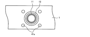
- FIG. 10 is a top view around the fin collar 11 of the heat exchanger 10 according to the fourth embodiment.
- the first to third embodiments are that a plurality of protrusions 41a and 41b are provided around the fin collar 11 of the heat exchanger 10 according to the fourth embodiment.
- the other configuration of the heat exchanger 10 is the same as that of the first to third embodiments, the description thereof is omitted, and the same reference numerals are given to the same or corresponding parts as the heat exchanger 10.
- the fin 1 is provided with a plurality of protrusions 41a and 41b on the outer peripheral side of the resin member 12 disposed on the outer peripheral side of the fin collar 11 protruding from the surface of the fin 1 in the stacking direction.
- the plurality of protrusions 41 a and 41 b protrude from the surface of the fin 1 in the stacking direction, and are formed at a height in the stacking direction that is substantially the same as the height of the resin member 12 in the stacking direction.
- the plurality of protrusions 41 a and 41 b have a circular shape or the like when viewed from above, and are scattered on the outer peripheral side of the resin member 12.
- the plurality of protrusions 41a and the protrusions 41b have the same shape and are arranged at positions shifted in the stacking direction.
- the plurality of fins 1 are stacked such that the top surfaces of the plurality of protrusions 41 a and 41 b and the top surface of the resin member 12 are in contact with the back surface of the fins 1.
- the plurality of protrusions 41 a and 41 b provided on the fin 1 prevent the fin 1 from being inclined with respect to the adjacent fin 1, and the distance between the stacked fins 1 is kept constant.
- the fins 1 to be stacked can easily maintain the distance between the fins 1 by shifting the positions of the protrusions 41 a and the protrusions 41 b of the adjacent fins 1.
- the resin member 12 employs a configuration that expands to seal the gap between the fins by reacting after assembly using an adhesive mixed with a reactive foam material or thermally expandable microcapsules. Also good.
- the protrusions 41a and 41b may have a circular cylindrical shape in a top view, but may have a rectangular parallelepiped shape in a top view, and the shape is not limited.
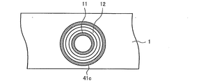
- FIG. 11 is a top view of the protrusion 41c of the heat exchanger 10 according to the fourth embodiment.
- the protrusion 41 c has an annular shape having an inner diameter larger than that of the resin member 12 in a top view.
- the protrusion 41c may be formed in an annular shape surrounding the resin member 12 in a top view, and in this case as well, the distance between the laminated fins 1 is kept constant.
- the heat transferred from the hot water RF to the fin collar 11 reaches the fin 1 from the fin collar 11 and a plurality of protrusions 41 a and 41 b arranged on the outer peripheral side of the resin member 12 of the fin 1. Then, the interior of the fin 1 and the plurality of protrusions 41a and 41b projecting from the fin 1 are warmed by being dissipated by the air WF that flows around them.
- the plurality of protrusions 41a and 41b increase the contact area between the fins 1 and the air WF and improve the efficiency of heat exchange.
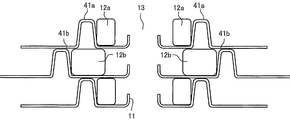
- FIG. 12 is a schematic diagram illustrating a cross section around the fin collar 11 of the heat exchanger 10 according to the first modification of the fourth embodiment.
- the heat exchanger 10 according to the first modification of the fourth embodiment includes resin members 12a and 12b arranged in contact with the inner peripheral surfaces of the protrusions 41a and 41b.
- the resin member 12a is formed in an annular shape having an outer diameter equal to or smaller than the inner diameter of the protrusion 41a and an inner diameter larger than the outer diameter of the fin collar 11 in a top view.
- the resin member 12b has an annular shape having an outer diameter equal to or smaller than the inner diameter of the protrusion 41b disposed on the outer peripheral side than the protrusion 41a and an inner diameter larger than the outer diameter of the fin collar 11 in a top view. Formed.
- the inner diameter of the resin member 12a is larger than the inner diameter of the resin member 12b.
- the resin members 12a and 12b are fitted inside the protrusions 41a and 41b in a state where the outer peripheral surfaces of the resin members 12a and 12b are in contact with the inner peripheral surfaces of the protrusions 41a and 41b.
- the internal pressure of the liquid passage 13 is received by both the resin members 12a and 12b and the protrusions 41a and 41b that are in contact with the outer periphery of the resin members 12a and 12b.
- the pressure strength of the liquid passage 13 is improved.
- the liquid contact area between the fin 1 and the heat transfer medium inside the liquid passage tube 13 is increased, and the effective area for heat exchange is increased.
- FIG. 13 is a schematic diagram showing a cross section around the fin collar 11 of the heat exchanger 10 according to the second modification of the fourth embodiment.
- the heat exchanger 10 according to the second modification of the fourth embodiment includes protrusions 41 a and 41 b and recesses 42 a and 42 b into which the upper surfaces of the protrusions 41 a and 41 b are inserted.
- the recesses 42a and 42b are recesses formed on the back surface of the fin 1 at positions above the protrusions 41a and 41b, and are formed in the same area as the upper surfaces of the protrusions 41a and 41b. In a state where the plurality of fins 1 are stacked, the upper surfaces of the protrusions 41a and 41b are inserted into the recesses 42a and 42b, and are in contact with the back surfaces of the recesses 42a and 42b.
- the recesses 42a and 42b may be formed so that the difference between the height of the protrusions 41a and 41b and the depth of the recesses 42a and 42b is equal to the distance between the adjacent fins 1 and the height of the resin member 12.
- Protrusions 41 a and 41 b are provided on the surface of the fin 1, and recesses 42 a and 42 b are formed on the back surface of the fin 1.
- the protrusions 41 a and 41 b are inserted into the recesses 42 a and 42 b, thereby positioning the stacked fins 1. And the centers of the fin collars 11 to be laminated coincide.
- FIG. 14 is a schematic diagram showing a cross section around the fin collar 11 of the heat exchanger 10 according to the third modification of the fourth embodiment.
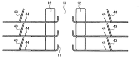
- the heat exchanger 10 according to the third modification of the fourth embodiment includes a cut and raised portion 43 and a cut portion 44 in the fin 1 on the outer peripheral side of the resin member 12.
- the cut and raised portion 43 is formed by putting a plurality of cut portions 44 into the fin 1 and raising the cut portions 44 in the stacking direction of the fins 1.
- the cut portion 44 may be formed in a direction parallel to the flow direction of the air WF, and the cut and raised portion 43 is formed, for example, at a height in the stacking direction equivalent to the interval between the stacked fins 1. Since the cut-and-raised portion 43 is parallel to the flow of the air WF in the direction perpendicular to the stacking direction of the fins 1, the contact with the air WF is facilitated, and the heat transfer between the fins 1 and the air WF is promoted by the leading edge effect. Is done.
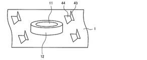
- FIG. 15 is a perspective view around the fin collar 11 of the heat exchanger 10 according to the third modification of the fourth embodiment.
- the cut-and-raised portion 43 of the fin 1 according to the third modification of the fourth embodiment may be formed in a trapezoidal shape. If the cut-and-raised portion 43 is formed in a trapezoidal shape, the cut-and-raised portion 43 can also serve as a function of maintaining the distance between the fins 1.
- the protrusions 41 a and 41 b that protrude from the surface of the fin 1 are provided on the outer peripheral sides of the fin collar 11 and the resin member 12.
- the distance between the fins 1 is appropriately maintained, so that the assemblability is improved.
- the adjacent fins are used to react after assembly and expand to seal the clearance of the fins 1. The distance of 1 is maintained and the assemblability is improved.
- protrusion 41a, 41b is comprised by the annular
- the heat exchanger 10 which concerns on Embodiment 4, it has the recessed parts 42a and 42b by which the upper surface of protrusion 41a, 41b is inserted in the back surface of the fin 1. As shown in FIG. Thereby, the distance between the adjacent fins 1 is constant, and the position of the laminated fin collars 11 is prevented from shifting.
- the fin 1 is formed with the cut portion 44 and the cut and raised portion 43 provided on the outer peripheral side of the resin member 12.
- the cut and raised portion 43 facilitates contact between the fin 1 and the air WF, and heat transfer between the fin 1 and the air WF is promoted by the front edge effect.
- Embodiment 5 FIG.
- the fin collar 11 of the heat exchanger 10 according to the fifth embodiment is different from the first to fourth embodiments in that the fin collar 11 has a protruding portion 11b protruding inward.
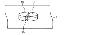
- FIG. 16 is a schematic diagram for explaining the fin collar 11 of the heat exchanger 10 according to the fifth embodiment.
- FIG. 17 is a perspective view of the fin collar 11 of FIG. FIG. 16 corresponds to FIG. 3 shown in the description of the first embodiment.
- the heat exchanger 10 according to the fifth embodiment includes a plurality of laminated fins 1, fin collars 11 formed on the fins 1, and a resin that is a tubular portion.
- the member 12 is comprised.
- Each of the plurality of fins 1 is a metal member such as aluminum having a flat plate shape, and the plurality of fins 1 are stacked in a direction orthogonal to the air flow direction. That is, each of the plurality of fins 1 is arranged in parallel with an interval. A plurality of openings 110 are provided on the surface of each fin 1.
- the plurality of fins 1 are stacked such that the centers of the plurality of openings 110 coincide with each other and a resin member 12 that is a cylindrical member is interposed therebetween.
- the stacked openings 110 and the resin member 12 form a liquid flow pipe 13 in the stacking direction of the plurality of fins 1. That is, in the stacked fins 1, two rows are formed in the row direction, and a plurality of liquid passage tubes 13 are formed in the step direction for each row.
- the resin member 12 has a cylindrical shape having an inner diameter larger than the outer diameter of the opening 110, and is disposed on the outer peripheral side of the opening 110 so as to surround the opening 110.
- the inner diameter of the resin member 12 is larger than the outer diameter of the opening 110, and the central axis of the resin member 12 and the central axis of the opening 110 coincide with each other.
- the resin member 12 is an example of a cylindrical member of the present invention.
- the opening 110 is provided with a fin collar 11 protruding from one surface of the fin 1 in the stacking direction.
- the fin collar 11 is formed with a rectangular convex portion 11 b that protrudes inward, and is arranged along the flow of the fluid flowing through the liquid passage 13. Two convex portions 11b are provided and arranged at positions facing each other.
- the fin collar 11 is an example of the second fin of the present invention.
- an inlet header 2 provided on the downstream side of the air WF flow and an outlet header 3 provided on the downstream side of the air WF flow via a plurality of connection pipes 4.
- the outlet header 3 is connected to the resin member 12 disposed on the fin 1 at one end of the fins 1 to be laminated through the flanges of the plurality of connecting pipes 4 branched from the outlet header 3.
- the inlet header 2 is also connected to the resin member 12 of the fin 1 arranged at one end by the same configuration as the outlet header 3.
- the inlet header 2 and the outlet header 3 are connected to the liquid flow pipe 13 by the resin member 12 to which each is connected.
- the inlet header 2 and the outlet header 3 connect the liquid passage 13 extending from the inlet header 2 and the liquid passage 13 extending toward the outlet header 3 at the other end of the plurality of fins 1 to be stacked. They are connected by a U-shaped tube (not shown).
- the heat transfer medium is heated by heat exchange in the outdoor unit and flows into the indoor unit as hot water RF.
- the hot water RF flows in from the inlet header 2 of the heat exchanger 10 accommodated in the indoor unit, and flows through the liquid passage pipes 13 positioned on the downstream side of the air WF via the connection pipes 4.
- the hot water RF that has flowed through the respective flow pipes 13 on the downstream side of the air WF flows into the respective liquid flow pipes 13 positioned on the upstream side of the air WF via U-shaped pipes.
- the hot water RF that has flowed through the liquid passages 13 on the upstream side of the air WF joins and flows through the outlet header 3 via the connection pipes 4 and flows out toward the outdoor unit.
- the heat transfer medium In the cooling operation of the air conditioner, the heat transfer medium is cooled by heat exchange in the outdoor unit, flows into the indoor unit as cold water RF, and flows through the heat exchanger 10.
- the flow of the cold water RF in the heat exchanger 10 is the same as the flow during the heating operation.
- the indoor air WF is sucked by the blower of the indoor unit, and blown into the room in the flow direction of the air WF via the heat exchanger 10.
- the air WF sucked by the blower flows into the fin core 14 between the fins 1 adjacent to each other in the stacking direction from the direction orthogonal to the stacking direction of the fins 1.
- the air WF exchanges heat with the hot water RF in each flow-through pipe 13 located on the windward side, and exchanges heat with the hot water RF in each liquid-flow pipe 13 located on the leeward side to become warm air. It flows out into the room.
- the air WF that has become the cold air is sent into the room by the cold water RF that flows in the liquid passing pipes 13 on the leeward side and the windward side.
- the flow of the liquid flow pipe Becomes laminar and heat exchange performance decreases.
- the protrusion 11b is arranged inside the fin collar 11 along the flow of the fluid flowing through the liquid passage 13, so that the flow is laminar. Even in the case of heat treatment, heat exchange performance is improved by the leading edge effect.
- the leading edge effect refers to an effect that a thin temperature boundary layer is formed from the leading edge portion of the tip of the fin that is placed in the laminar flow so as to improve the heat transfer coefficient.
- the case where two convex portions 11b are arranged in the circumferential direction of the fin collar 11 is shown.
- the number of the convex parts 11b may be one and it is not limited, the larger one can improve the heat transfer promotion effect.
- FIG. 18 is a perspective view of the fin collar 11 formed on the fin 1 adjacent to the fin 1 of FIG.
- the convex part 11c is formed in the fin 1 adjacent to the fin 1 shown in FIG.
- the convex portion 11c is arranged at a position shifted from the convex portion 11b by a half pitch in the circumferential direction.
- the convex part 11c is made into the offset fin arrangement
- the fin collar 11 has the convex portions 11b and 11c protruding inward, the heat exchange performance can be effectively improved even when the flow is laminarized.
- the flow rate of water which is a heat transfer medium, decreases due to the increase in the operation frequency of air conditioners in the mid-season when the air conditioning load is relatively small, such as spring and autumn, and the decrease in air conditioning load caused by high insulation of buildings and houses.
- the operating ratio of laminar flow is increasing. For this reason, the need to improve heat exchange performance even when laminarized is becoming increasingly important.
- the convex parts 11b and 11c are an example of the rectangular-shaped protrusion part of this invention.
- FIG. 19 is a schematic diagram for explaining the fin collar 11 of the heat exchanger 10 according to the modification of the fifth embodiment.
- FIG. 20 is a perspective view of the fin collar 11 of FIG. FIG. 16 corresponds to FIG. 3 shown in the description of the first embodiment.
- the fin collar 11 that protrudes in the stacking direction at the opening 110 is formed with a protruding portion 11 d that protrudes in a hemispherical shape.
- the protruding portion 11d has, for example, a shape that is recessed from the outer surface, and is disposed along the flow of the fluid that flows through the liquid passage 13.
- the two protruding portions 11d are arranged at positions facing each other. Also in the modified example, as in the fifth embodiment, even when the flow of the liquid passage 13 is laminarized, the heat exchange performance is improved by the leading edge effect.
- FIG. 21 is a perspective view of the fin collar 11 formed on the fin 1 adjacent to the fin 1 of FIG.
- the protrusion 1e is formed in the fin 1 adjacent to the fin 1 shown in FIG. 20, and it arrange
- the offset fin arrangement shifted by a half pitch in the circumferential direction can suppress the influence of the wake of the second fin arranged upstream, and further improve the heat transfer performance.
- Embodiment 6 FIG.
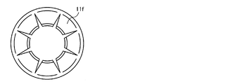
- the heat exchanger 10 according to the sixth embodiment is different from the first to fifth embodiments in that a plurality of bent portions 11f are formed in the circumferential direction of the opening 110 as second fins.
- FIG. 22 is a schematic diagram illustrating the fin collar 11 of the heat exchanger 10 according to the sixth embodiment.
- 23 and 24 are a schematic view and a perspective view of the fin collar 11 shown in FIG. 23 viewed from the flow direction of the liquid pipe 13.
- FIG. 22 is a diagram corresponding to FIG. 3 shown in the description of the first embodiment.
- the fin collar 11 of the plurality of fins 1 includes the plurality of bent portions 11 f formed in the opening 110. I have.
- the plurality of bent portions 11f are bent in the same direction so that the tip portions thereof are along the liquid passage tube 13, and are arranged in the circumferential direction.
- the bent portion 11f formed inside the opening 110 is intermittently disposed in the circumferential direction at the tip portion, and the flow is made laminar by following the flow of the fluid flowing through the liquid passage 13. Even when doing so, the heat exchange performance is improved by the leading edge effect. Moreover, since the clearance gap arrange
- the number of the bent portions 11f may be two, and the number is not limited, but a larger number can improve the heat transfer promotion effect.
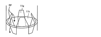
- FIG. 25 is a schematic diagram illustrating the fin collar 11 of the heat exchanger 10 according to the first modification of the sixth embodiment.
- 26 and 27 are a schematic view and a perspective view of the fin collar 11 shown in FIG. 25 viewed from the flow direction of the liquid pipe 13.
- FIG. 22 is a diagram corresponding to FIG. 3 shown in the description of the first embodiment.
- the arrow has shown the flow of water RF which is a heat carrier medium.
- the fin collars 11 of the plurality of fins 1 include a plurality of bent portions 11g and 11h formed in the circumferential direction inside the opening 110.
- the plurality of bent portions 11g and 11h are arranged such that the tip portions thereof are along the liquid passing pipe 13 and the adjacent bent portions 11g and 11h are bent in opposite directions.
- the heat transfer medium can pass through a large gap formed in the circumferential direction between the adjacent bent portions 11g and 11h. .
- the effect that flow resistance can further be suppressed and heat exchange performance can be improved is obtained.
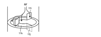
- FIG. 28 is a schematic diagram illustrating the fin collar 11 of the heat exchanger 10 according to the second modification of the sixth embodiment.
- 29 and 30 are a schematic view and a perspective view of the fin collar 11 shown in FIG. 28 viewed from the flow direction of the liquid pipe 13.
- FIG. 22 is a diagram corresponding to FIG. 3 shown in the description of the first embodiment.
- the arrow has shown the flow of water RF which is a heat carrier medium.
- the fin collar 11 of the plurality of fins 1 includes a plurality of bent portions 11 i and 11 j and a flat portion 11 k formed in the circumferential direction inside the opening 110. Is provided.
- the plurality of 11 i and 11 j are bent along the flow of the liquid pipe 13 through a part in the circumferential direction of the opening 110, and the flat part 11 k is perpendicular to the liquid pipe 13.
- the bent portions 11i and 11j that bend from the flat portion 11k so that a part of the circumferential direction follows the flow of the liquid passing tube 13 are as described in the sixth embodiment and the first modification of the sixth embodiment.
- a gap is formed. Thereby, the effect that flow resistance can be suppressed and heat exchange performance can be improved is acquired.
- tip of the adjacent bending parts 11i and 11j of this modification is bent and arrange
- the larger the area of the bent portions 11i and 11j the more the heat transfer is improved by the leading edge effect and the flow resistance is reduced.
- the bent portions 11i and 11j are separated from the fin 1 in the radial direction, that is, in the heat transfer direction. For this reason, since the heat conduction loss also increases, there are optimum areas of the bent portions 11i and 11j.
- the bent portions 11f, 11g, and 11h are divided in the circumferential direction, that is, in a direction perpendicular to the heat transfer, and therefore the heat transfer is reduced due to the division. There is no.
Landscapes
- Engineering & Computer Science (AREA)
- Physics & Mathematics (AREA)
- Thermal Sciences (AREA)
- Mechanical Engineering (AREA)
- General Engineering & Computer Science (AREA)
- Geometry (AREA)
- Chemical & Material Sciences (AREA)
- Crystallography & Structural Chemistry (AREA)
- Heat-Exchange Devices With Radiators And Conduit Assemblies (AREA)
Abstract
L'invention concerne un échangeur de chaleur conçu pour garantir une efficacité d'échange de chaleur et une résistance à la corrosion fiable. L'échangeur de chaleur comprend : une pluralité d'ailettes tabulaires plates ; des ouvertures disposées respectivement dans la pluralité d'ailettes ; et des éléments cylindriques disposés chacun sur le côté périphérique externe d'une ouverture correspondante parmi les ouvertures et présentant un diamètre interne supérieur au diamètre externe de l'ouverture. Les ailettes sont empilées ensemble tandis que les éléments cylindriques sont situés entre les ailettes. Les ouvertures et les éléments cylindriques forment des conduits d'écoulement de liquide. Les ouvertures font saillie vers l'intérieur plus loin que les éléments cylindriques.
Priority Applications (3)
| Application Number | Priority Date | Filing Date | Title |
|---|---|---|---|
| US16/082,497 US11054186B2 (en) | 2016-04-15 | 2017-03-24 | Heat exchanger |
| DE112017002007.7T DE112017002007B4 (de) | 2016-04-15 | 2017-03-24 | Wärmetauscher |
| JP2018511952A JP6559334B2 (ja) | 2016-04-15 | 2017-03-24 | 熱交換器 |
Applications Claiming Priority (2)
| Application Number | Priority Date | Filing Date | Title |
|---|---|---|---|
| JP2016081696 | 2016-04-15 | ||
| JP2016-081696 | 2016-04-15 |
Publications (1)
| Publication Number | Publication Date |
|---|---|
| WO2017179399A1 true WO2017179399A1 (fr) | 2017-10-19 |
Family
ID=60041511
Family Applications (1)
| Application Number | Title | Priority Date | Filing Date |
|---|---|---|---|
| PCT/JP2017/012036 Ceased WO2017179399A1 (fr) | 2016-04-15 | 2017-03-24 | Échangeur de chaleur |
Country Status (4)
| Country | Link |
|---|---|
| US (1) | US11054186B2 (fr) |
| JP (1) | JP6559334B2 (fr) |
| DE (1) | DE112017002007B4 (fr) |
| WO (1) | WO2017179399A1 (fr) |
Families Citing this family (2)
| Publication number | Priority date | Publication date | Assignee | Title |
|---|---|---|---|---|
| WO2019062493A1 (fr) * | 2017-09-30 | 2019-04-04 | 杭州三花微通道换热器有限公司 | Échangeur de chaleur et ailette |
| US11835306B2 (en) * | 2021-03-03 | 2023-12-05 | Rheem Manufacturing Company | Finned tube heat exchangers and methods for manufacturing same |
Citations (11)
| Publication number | Priority date | Publication date | Assignee | Title |
|---|---|---|---|---|
| JPS49135841U (fr) * | 1973-03-07 | 1974-11-22 | ||
| JPS547659A (en) * | 1977-06-18 | 1979-01-20 | Akira Tane | Pipeless heat exchanger |
| JPS5463554U (fr) * | 1977-10-14 | 1979-05-04 | ||
| JPS56121995A (en) * | 1980-02-29 | 1981-09-25 | Hitachi Ltd | Manufacture of heat exchanger |
| JPS56168086A (en) * | 1979-11-30 | 1981-12-24 | Lambda Energy Products Inc | Heat exchanger for evaporation-condensation |
| GB2129538A (en) * | 1982-11-03 | 1984-05-16 | Eric Smith | Heat exchanger |
| DE3242260A1 (de) * | 1982-11-15 | 1984-05-17 | Thermal-Werke, Wärme-, Kälte-, Klimatechnik GmbH, 6909 Walldorf | Waermetauscher |
| JPS6397077U (fr) * | 1986-12-08 | 1988-06-23 | ||
| US5318112A (en) * | 1993-03-02 | 1994-06-07 | Raditech Ltd. | Finned-duct heat exchanger |
| JP2008089230A (ja) * | 2006-10-02 | 2008-04-17 | Matsushita Electric Ind Co Ltd | フィンアンドチューブ型熱交換器 |
| JP2010096413A (ja) * | 2008-10-16 | 2010-04-30 | Kobe Steel Ltd | 耐久性部材、および、これを用いたオープンラック式気化器 |
Family Cites Families (31)
| Publication number | Priority date | Publication date | Assignee | Title |
|---|---|---|---|---|
| US1870012A (en) * | 1927-05-28 | 1932-08-02 | Karmazin John | Radiator construction |
| US1940804A (en) * | 1930-04-09 | 1933-12-26 | Karmazin Engineering Company | Radiator |
| US2804286A (en) | 1955-03-18 | 1957-08-27 | Pintarelli Ralph | Radiation fins |
| US3250323A (en) * | 1962-01-23 | 1966-05-10 | Karmazin Prod | Heat exchanger |
| FR2191087B1 (fr) * | 1972-07-05 | 1977-05-13 | Delamair Limited | |
| JPS5230955A (en) | 1975-09-04 | 1977-03-09 | Yoshihiro Ishizaki | Heat-exchanger |
| JPS54114850A (en) | 1978-02-28 | 1979-09-07 | Nihon Radiator Co | Heat exchanger |
| JPS5553698A (en) * | 1978-10-17 | 1980-04-19 | Mitsubishi Heavy Ind Ltd | Finned tube type heat exchanger |
| JPS586394A (ja) | 1981-07-06 | 1983-01-13 | Hitachi Ltd | 熱交換器の製作法 |
| JPS58127092A (ja) | 1982-01-25 | 1983-07-28 | Nippon Denso Co Ltd | 熱交換器及びその製法 |
| CH666538A5 (de) * | 1985-05-15 | 1988-07-29 | Sulzer Ag | Waermeuebertrager mit mehreren parallelen rohren und auf diesen angebrachten rippen. |
| JPH09119792A (ja) * | 1995-10-25 | 1997-05-06 | Hidaka Seiki Kk | 熱交換器用フィン |
| JP3038179B2 (ja) * | 1998-04-08 | 2000-05-08 | 日高精機株式会社 | 熱交換器用フィン及びその製造方法 |
| JP2000138331A (ja) | 1998-10-29 | 2000-05-16 | Sanko:Kk | ヒートシンク及びその製造方法 |
| US6266882B1 (en) * | 1999-05-20 | 2001-07-31 | Carrier Corporation | Fin collar and method of manufacturing |
| JP3769594B2 (ja) * | 2002-05-07 | 2006-04-26 | 三菱電機株式会社 | 熱交換器フィン形成金型 |
| US20070023177A1 (en) * | 2005-07-27 | 2007-02-01 | Li-Ping Lee | Cooling fin assembly |
| DE502006005252D1 (de) | 2006-08-08 | 2009-12-10 | Behr Gmbh & Co Kg | Rippe für einen Wärmeübertrager, Wärmeübertrager mit einer solchen Rippe und Verfahren zur Herstellung des Wärmeübertragers |
| JP4169079B2 (ja) * | 2006-10-02 | 2008-10-22 | ダイキン工業株式会社 | フィンチューブ型熱交換器 |
| JP4293252B2 (ja) * | 2007-03-19 | 2009-07-08 | ダイキン工業株式会社 | 熱交換器用フィン、並びにガイド及びその使用方法 |
| JP5304024B2 (ja) * | 2008-05-27 | 2013-10-02 | ダイキン工業株式会社 | フィンチューブ型熱交換器 |
| JP2011021824A (ja) | 2009-07-16 | 2011-02-03 | Kakinuma Kinzoku Seiki Kk | 熱交換器及び熱交換器のフィンの延出部の形成方法 |
| US20110203782A1 (en) * | 2010-02-19 | 2011-08-25 | Blissfield Manufacturing Company | Heat exchanger fins, assemblies and methods |
| KR20120054321A (ko) * | 2010-11-19 | 2012-05-30 | 엘지전자 주식회사 | 히트 펌프 |
| CN103403486B (zh) * | 2011-03-01 | 2015-12-09 | 三菱电机株式会社 | 热交换器以及具备该热交换器的冰箱、空气调节器 |
| SG11201406541QA (en) * | 2012-04-12 | 2014-11-27 | Carrier Corp | Sacrificial aluminum fins for failure mode protection of an aluminum heat exchanger |
| US8754470B1 (en) * | 2013-01-18 | 2014-06-17 | Taiwan Semiconductor Manufacturing Company, Ltd. | Vertical tunneling field-effect transistor cell and fabricating the same |
| WO2014167827A1 (fr) * | 2013-04-09 | 2014-10-16 | パナソニック株式会社 | Ailette de transfert de chaleur, échangeur de chaleur et dispositif à cycle frigorifique |
| ITTO20130664A1 (it) | 2013-08-02 | 2015-02-03 | T R A Refrigeranti S P A As | Gruppo refrigerante di gas |
| US10041739B2 (en) * | 2014-09-08 | 2018-08-07 | Mitsubishi Electric Corporation | Heat exchanger and method for manufacturing plate-shaped fins for heat exchanger |
| GB2545109B (en) * | 2014-09-25 | 2020-09-30 | Mitsubishi Electric Corp | Refrigerant pipe, method of manufacturing the refrigerant pipe, and heat exchanger including the refrigerant pipe |
-
2017
- 2017-03-24 WO PCT/JP2017/012036 patent/WO2017179399A1/fr not_active Ceased
- 2017-03-24 JP JP2018511952A patent/JP6559334B2/ja not_active Expired - Fee Related
- 2017-03-24 DE DE112017002007.7T patent/DE112017002007B4/de not_active Expired - Fee Related
- 2017-03-24 US US16/082,497 patent/US11054186B2/en not_active Expired - Fee Related
Patent Citations (11)
| Publication number | Priority date | Publication date | Assignee | Title |
|---|---|---|---|---|
| JPS49135841U (fr) * | 1973-03-07 | 1974-11-22 | ||
| JPS547659A (en) * | 1977-06-18 | 1979-01-20 | Akira Tane | Pipeless heat exchanger |
| JPS5463554U (fr) * | 1977-10-14 | 1979-05-04 | ||
| JPS56168086A (en) * | 1979-11-30 | 1981-12-24 | Lambda Energy Products Inc | Heat exchanger for evaporation-condensation |
| JPS56121995A (en) * | 1980-02-29 | 1981-09-25 | Hitachi Ltd | Manufacture of heat exchanger |
| GB2129538A (en) * | 1982-11-03 | 1984-05-16 | Eric Smith | Heat exchanger |
| DE3242260A1 (de) * | 1982-11-15 | 1984-05-17 | Thermal-Werke, Wärme-, Kälte-, Klimatechnik GmbH, 6909 Walldorf | Waermetauscher |
| JPS6397077U (fr) * | 1986-12-08 | 1988-06-23 | ||
| US5318112A (en) * | 1993-03-02 | 1994-06-07 | Raditech Ltd. | Finned-duct heat exchanger |
| JP2008089230A (ja) * | 2006-10-02 | 2008-04-17 | Matsushita Electric Ind Co Ltd | フィンアンドチューブ型熱交換器 |
| JP2010096413A (ja) * | 2008-10-16 | 2010-04-30 | Kobe Steel Ltd | 耐久性部材、および、これを用いたオープンラック式気化器 |
Also Published As
| Publication number | Publication date |
|---|---|
| JP6559334B2 (ja) | 2019-08-14 |
| US20190086153A1 (en) | 2019-03-21 |
| JPWO2017179399A1 (ja) | 2018-11-08 |
| US11054186B2 (en) | 2021-07-06 |
| DE112017002007B4 (de) | 2024-07-04 |
| DE112017002007T5 (de) | 2019-01-24 |
Similar Documents
| Publication | Publication Date | Title |
|---|---|---|
| CN103403488B (zh) | 具有热膨胀连接器的同轴气液热交换器 | |
| JP5140051B2 (ja) | 熱交換器および熱交換器用フィンとその製造方法 | |
| US8584742B2 (en) | Heat exchanger | |
| CN103925826A (zh) | 热交换器用管 | |
| CN104011494A (zh) | 排气热交换装置 | |
| WO2012132924A1 (fr) | Échangeur de chaleur | |
| KR20140103895A (ko) | 핀 튜브형 열교환기 | |
| JP6559334B2 (ja) | 熱交換器 | |
| US7036568B2 (en) | Heat exchanger having projecting fluid passage | |
| WO2017010120A1 (fr) | Échangeur thermique et dispositif de climatisation | |
| JP2010121925A (ja) | 熱交換器 | |
| JP5741470B2 (ja) | 熱交換器、およびその製造方法 | |
| JP4414199B2 (ja) | 2重管式熱交換器 | |
| CN113383205B (zh) | 换热器 | |
| JP2012159211A (ja) | 熱交換器 | |
| JP2015090219A (ja) | 熱交換器の拡管方法及び空気調和機 | |
| JP2005274010A (ja) | 積層型熱交換器 | |
| JP6486225B2 (ja) | 熱交換器 | |
| WO2012043380A1 (fr) | Échangeur de chaleur | |
| JP2007017061A (ja) | 炭酸ガスエアコン用ガスクーラ | |
| JP4450174B2 (ja) | 熱交換器 | |
| JP2014052147A (ja) | 熱交換器及びその製造方法 | |
| JP2000205785A (ja) | 熱交換器 | |
| JP2005037031A (ja) | 熱交換器の接合構造 | |
| JP6601380B2 (ja) | 熱交換器および空気調和装置 |
Legal Events
| Date | Code | Title | Description |
|---|---|---|---|
| WWE | Wipo information: entry into national phase |
Ref document number: 2018511952 Country of ref document: JP |
|
| 121 | Ep: the epo has been informed by wipo that ep was designated in this application |
Ref document number: 17782217 Country of ref document: EP Kind code of ref document: A1 |
|
| 122 | Ep: pct application non-entry in european phase |
Ref document number: 17782217 Country of ref document: EP Kind code of ref document: A1 |