WO2017179465A1 - Unité émettrice de lumière et accessoire de lampe de véhicule - Google Patents
Unité émettrice de lumière et accessoire de lampe de véhicule Download PDFInfo
- Publication number
- WO2017179465A1 WO2017179465A1 PCT/JP2017/014175 JP2017014175W WO2017179465A1 WO 2017179465 A1 WO2017179465 A1 WO 2017179465A1 JP 2017014175 W JP2017014175 W JP 2017014175W WO 2017179465 A1 WO2017179465 A1 WO 2017179465A1
- Authority
- WO
- WIPO (PCT)
- Prior art keywords
- light source
- light emitting
- positioning
- reflector
- emitting unit
- Prior art date
- Legal status (The legal status is an assumption and is not a legal conclusion. Google has not performed a legal analysis and makes no representation as to the accuracy of the status listed.)
- Ceased
Links
Images


Classifications
-
- F—MECHANICAL ENGINEERING; LIGHTING; HEATING; WEAPONS; BLASTING
- F21—LIGHTING
- F21S—NON-PORTABLE LIGHTING DEVICES; SYSTEMS THEREOF; VEHICLE LIGHTING DEVICES SPECIALLY ADAPTED FOR VEHICLE EXTERIORS
- F21S41/00—Illuminating devices specially adapted for vehicle exteriors, e.g. headlamps
- F21S41/10—Illuminating devices specially adapted for vehicle exteriors, e.g. headlamps characterised by the light source
- F21S41/14—Illuminating devices specially adapted for vehicle exteriors, e.g. headlamps characterised by the light source characterised by the type of light source
- F21S41/141—Light emitting diodes [LED]
- F21S41/147—Light emitting diodes [LED] the main emission direction of the LED being angled to the optical axis of the illuminating device
- F21S41/148—Light emitting diodes [LED] the main emission direction of the LED being angled to the optical axis of the illuminating device the main emission direction of the LED being perpendicular to the optical axis
-
- B—PERFORMING OPERATIONS; TRANSPORTING
- B60—VEHICLES IN GENERAL
- B60Q—ARRANGEMENT OF SIGNALLING OR LIGHTING DEVICES, THE MOUNTING OR SUPPORTING THEREOF OR CIRCUITS THEREFOR, FOR VEHICLES IN GENERAL
- B60Q1/00—Arrangement of optical signalling or lighting devices, the mounting or supporting thereof or circuits therefor
- B60Q1/02—Arrangement of optical signalling or lighting devices, the mounting or supporting thereof or circuits therefor the devices being primarily intended to illuminate the way ahead or to illuminate other areas of way or environments
- B60Q1/04—Arrangement of optical signalling or lighting devices, the mounting or supporting thereof or circuits therefor the devices being primarily intended to illuminate the way ahead or to illuminate other areas of way or environments the devices being headlights
- B60Q1/06—Arrangement of optical signalling or lighting devices, the mounting or supporting thereof or circuits therefor the devices being primarily intended to illuminate the way ahead or to illuminate other areas of way or environments the devices being headlights adjustable, e.g. remotely-controlled from inside vehicle
- B60Q1/068—Arrangement of optical signalling or lighting devices, the mounting or supporting thereof or circuits therefor the devices being primarily intended to illuminate the way ahead or to illuminate other areas of way or environments the devices being headlights adjustable, e.g. remotely-controlled from inside vehicle by mechanical means
- B60Q1/0683—Adjustable by rotation of a screw
-
- F—MECHANICAL ENGINEERING; LIGHTING; HEATING; WEAPONS; BLASTING
- F21—LIGHTING
- F21S—NON-PORTABLE LIGHTING DEVICES; SYSTEMS THEREOF; VEHICLE LIGHTING DEVICES SPECIALLY ADAPTED FOR VEHICLE EXTERIORS
- F21S41/00—Illuminating devices specially adapted for vehicle exteriors, e.g. headlamps
-
- F—MECHANICAL ENGINEERING; LIGHTING; HEATING; WEAPONS; BLASTING
- F21—LIGHTING
- F21S—NON-PORTABLE LIGHTING DEVICES; SYSTEMS THEREOF; VEHICLE LIGHTING DEVICES SPECIALLY ADAPTED FOR VEHICLE EXTERIORS
- F21S41/00—Illuminating devices specially adapted for vehicle exteriors, e.g. headlamps
- F21S41/10—Illuminating devices specially adapted for vehicle exteriors, e.g. headlamps characterised by the light source
- F21S41/14—Illuminating devices specially adapted for vehicle exteriors, e.g. headlamps characterised by the light source characterised by the type of light source
- F21S41/16—Laser light sources
-
- F—MECHANICAL ENGINEERING; LIGHTING; HEATING; WEAPONS; BLASTING
- F21—LIGHTING
- F21S—NON-PORTABLE LIGHTING DEVICES; SYSTEMS THEREOF; VEHICLE LIGHTING DEVICES SPECIALLY ADAPTED FOR VEHICLE EXTERIORS
- F21S41/00—Illuminating devices specially adapted for vehicle exteriors, e.g. headlamps
- F21S41/10—Illuminating devices specially adapted for vehicle exteriors, e.g. headlamps characterised by the light source
- F21S41/14—Illuminating devices specially adapted for vehicle exteriors, e.g. headlamps characterised by the light source characterised by the type of light source
- F21S41/176—Light sources where the light is generated by photoluminescent material spaced from a primary light generating element
-
- F—MECHANICAL ENGINEERING; LIGHTING; HEATING; WEAPONS; BLASTING
- F21—LIGHTING
- F21S—NON-PORTABLE LIGHTING DEVICES; SYSTEMS THEREOF; VEHICLE LIGHTING DEVICES SPECIALLY ADAPTED FOR VEHICLE EXTERIORS
- F21S41/00—Illuminating devices specially adapted for vehicle exteriors, e.g. headlamps
- F21S41/10—Illuminating devices specially adapted for vehicle exteriors, e.g. headlamps characterised by the light source
- F21S41/19—Attachment of light sources or lamp holders
- F21S41/192—Details of lamp holders, terminals or connectors
-
- F—MECHANICAL ENGINEERING; LIGHTING; HEATING; WEAPONS; BLASTING
- F21—LIGHTING
- F21S—NON-PORTABLE LIGHTING DEVICES; SYSTEMS THEREOF; VEHICLE LIGHTING DEVICES SPECIALLY ADAPTED FOR VEHICLE EXTERIORS
- F21S41/00—Illuminating devices specially adapted for vehicle exteriors, e.g. headlamps
- F21S41/20—Illuminating devices specially adapted for vehicle exteriors, e.g. headlamps characterised by refractors, transparent cover plates, light guides or filters
- F21S41/285—Refractors, transparent cover plates, light guides or filters not provided in groups F21S41/24 - F21S41/2805
-
- F—MECHANICAL ENGINEERING; LIGHTING; HEATING; WEAPONS; BLASTING
- F21—LIGHTING
- F21S—NON-PORTABLE LIGHTING DEVICES; SYSTEMS THEREOF; VEHICLE LIGHTING DEVICES SPECIALLY ADAPTED FOR VEHICLE EXTERIORS
- F21S41/00—Illuminating devices specially adapted for vehicle exteriors, e.g. headlamps
- F21S41/30—Illuminating devices specially adapted for vehicle exteriors, e.g. headlamps characterised by reflectors
- F21S41/32—Optical layout thereof
- F21S41/321—Optical layout thereof the reflector being a surface of revolution or a planar surface, e.g. truncated
-
- F—MECHANICAL ENGINEERING; LIGHTING; HEATING; WEAPONS; BLASTING
- F21—LIGHTING
- F21S—NON-PORTABLE LIGHTING DEVICES; SYSTEMS THEREOF; VEHICLE LIGHTING DEVICES SPECIALLY ADAPTED FOR VEHICLE EXTERIORS
- F21S41/00—Illuminating devices specially adapted for vehicle exteriors, e.g. headlamps
- F21S41/30—Illuminating devices specially adapted for vehicle exteriors, e.g. headlamps characterised by reflectors
- F21S41/39—Attachment thereof
-
- F—MECHANICAL ENGINEERING; LIGHTING; HEATING; WEAPONS; BLASTING
- F21—LIGHTING
- F21S—NON-PORTABLE LIGHTING DEVICES; SYSTEMS THEREOF; VEHICLE LIGHTING DEVICES SPECIALLY ADAPTED FOR VEHICLE EXTERIORS
- F21S41/00—Illuminating devices specially adapted for vehicle exteriors, e.g. headlamps
- F21S41/60—Illuminating devices specially adapted for vehicle exteriors, e.g. headlamps characterised by a variable light distribution
- F21S41/67—Illuminating devices specially adapted for vehicle exteriors, e.g. headlamps characterised by a variable light distribution by acting on reflectors
- F21S41/675—Illuminating devices specially adapted for vehicle exteriors, e.g. headlamps characterised by a variable light distribution by acting on reflectors by moving reflectors
-
- F—MECHANICAL ENGINEERING; LIGHTING; HEATING; WEAPONS; BLASTING
- F21—LIGHTING
- F21V—FUNCTIONAL FEATURES OR DETAILS OF LIGHTING DEVICES OR SYSTEMS THEREOF; STRUCTURAL COMBINATIONS OF LIGHTING DEVICES WITH OTHER ARTICLES, NOT OTHERWISE PROVIDED FOR
- F21V29/00—Protecting lighting devices from thermal damage; Cooling or heating arrangements specially adapted for lighting devices or systems
- F21V29/50—Cooling arrangements
- F21V29/502—Cooling arrangements characterised by the adaptation for cooling of specific components
- F21V29/503—Cooling arrangements characterised by the adaptation for cooling of specific components of light sources
-
- F—MECHANICAL ENGINEERING; LIGHTING; HEATING; WEAPONS; BLASTING
- F21—LIGHTING
- F21V—FUNCTIONAL FEATURES OR DETAILS OF LIGHTING DEVICES OR SYSTEMS THEREOF; STRUCTURAL COMBINATIONS OF LIGHTING DEVICES WITH OTHER ARTICLES, NOT OTHERWISE PROVIDED FOR
- F21V29/00—Protecting lighting devices from thermal damage; Cooling or heating arrangements specially adapted for lighting devices or systems
- F21V29/50—Cooling arrangements
- F21V29/70—Cooling arrangements characterised by passive heat-dissipating elements, e.g. heat-sinks
-
- F—MECHANICAL ENGINEERING; LIGHTING; HEATING; WEAPONS; BLASTING
- F21—LIGHTING
- F21S—NON-PORTABLE LIGHTING DEVICES; SYSTEMS THEREOF; VEHICLE LIGHTING DEVICES SPECIALLY ADAPTED FOR VEHICLE EXTERIORS
- F21S45/00—Arrangements within vehicle lighting devices specially adapted for vehicle exteriors, for purposes other than emission or distribution of light
- F21S45/40—Cooling of lighting devices
- F21S45/47—Passive cooling, e.g. using fins, thermal conductive elements or openings
Definitions
- the present invention relates to a light emitting unit and a vehicle lamp.
- Patent Document 1 a light source unit for a vehicle headlamp using a semiconductor laser light source has been devised.
- the position of the optical axis in the actual product may differ from the design position within a range of tolerances such as the assembly accuracy of optical components.
- the positional deviation of the optical axis is very small, strictly speaking, it leads to an error in the irradiation position of light from the vehicular lamp. Since the semiconductor laser light source has high brightness and can illuminate far, a slight deviation of the optical axis can cause a relatively large irradiation position error. For light sources having other semiconductor light emitting elements, as good optical axis accuracy as possible is desired.
- the present invention has been made in view of such circumstances, and an object thereof is to provide a light emitting unit with improved optical axis accuracy and a vehicular lamp provided with the same.
- a light emitting unit includes a light source including a semiconductor light emitting element, a light source base that supports the light source, a heat radiating member to which the light source base is attached, and an optical member.
- the light source base includes an optical member positioning structure that positions the optical member with respect to the light source.
- both the light source and the optical member are supported by the light source base. Therefore, the optical member can be directly attached to the light source base without using the heat dissipation member.
- the heat dissipating member is not involved in accumulating dimensional tolerances from the light source to the optical member. Therefore, compared with the case where a light source base and an optical member are each assembled
- the optical member positioning structure may define a positioning surface around the optical axis of the light source.
- the optical member positioning structure may include a cylindrical positioning pin that forms a light source mounting recess in which the light source is mounted, and the positioning surface may be an outer peripheral surface or an inner peripheral surface of the cylindrical positioning pin.
- the optical member positioning structure may include a tip surface positioned at a first height in the optical axis direction, and the light emission surface of the light source may be positioned at a second height higher than the first height in the optical axis direction.
- the optical member positioning structure may include a positioning pin with a slit.
- a light emitting unit includes a light source including a semiconductor light emitting element, a light source support member that supports the light source, an optical member, and an optical member that can tilt about two different axes with respect to the light source.
- An optical member tilting mechanism provided on the light source support member.
- the light source support member is provided with the optical member tilting mechanism. Therefore, after attaching the light emitting unit to a predetermined place, the optical member can be tilted with respect to the light source by using the optical member tilting mechanism to correct the positional deviation of the optical axis. Therefore, the optical axis accuracy of the light emitting unit can be improved.
- the optical member tilting mechanism is configured such that the optical member can tilt with respect to the light source about the first tilting axis, and configured so that the optical member can tilt with respect to the light source about the second tilting axis.
- the tilting axis may be the optical axis of the light source, and the second tilting axis may be positioned at the height of the light emitting surface of the light source perpendicular to the optical axis.
- the light source support member may include a positioning structure that positions the optical member tilting mechanism with respect to the light source.
- the positioning structure may define a positioning surface around the optical axis of the light source.
- the positioning structure may include a tip surface positioned at a first height in the optical axis direction, and the light emission surface of the light source may be positioned at a second height higher than the first height in the optical axis direction.
- the light source support member may include a light source base that supports the light source, and a heat radiating member to which the light source base is attached or formed integrally with the light source base.
- the positioning structure may include a positioning pin with a slit.
- the vehicular lamp may include the light emitting unit described above.
- the present invention it is possible to provide a light emitting unit with improved accuracy of the optical axis and a vehicular lamp provided with the light emitting unit.
- FIG. 6A is a schematic top view of the laser light source and the light source base according to the first embodiment, and FIG.
- FIG. 6B is a schematic front view of the laser light source and the light source base according to the first embodiment.
- FIG. It is a schematic bottom view of the reflector which concerns on 1st Embodiment.
- It is a schematic front view of the light source base and reflector which concern on 1st Embodiment.
- FIG. 9 is a cross-sectional view taken along the line AA in FIG.
- It is a figure which shows schematically the internal structure of the vehicle lamp which concerns on 2nd Embodiment.
- It is a figure which shows schematically the internal structure of the laser light source which concerns on 2nd Embodiment.
- FIG. 13 is a schematic exploded perspective view of the light emitting unit shown in FIG. 12. It is a schematic sectional drawing of the light emission unit shown in FIG. It is a figure which illustrates the other light source which can be employ
- FIG. 16A is a schematic perspective view illustrating a first positioning pin with a slit
- FIG. 16B is a diagram illustrating conveyance of a laser light source.
- FIG. 1 is a diagram schematically showing the internal structure of a vehicular lamp 10 according to an embodiment.
- the vehicular lamp 10 is a left-side vehicular headlamp provided at the left end portion of the front end portion of the vehicle body, and the right vehicular lamp is a mirror image of the vehicular lamp 10 at the right end portion of the front end portion of the vehicle body. Headlights are arranged. Since the left vehicle headlamp and the right vehicle headlamp have the same structure, the left vehicle headlamp will be described below as an example.
- the vehicular lamp 10 includes a lamp body 12 having a recess opened forward and a translucent cover 14 that closes the opening of the lamp body 12.
- the lamp body 12 and the cover 14 constitute a lamp housing 16.
- An internal space of the lamp housing 16 is formed as a lamp chamber 18.
- a light emitting unit 20 In the lamp chamber 18, a light emitting unit 20, an extension 22, and an optical member 24 are arranged.
- the optical member 24 is provided to collect or squeeze the light emitted from the light emitting unit 20.
- the optical member 24 is, for example, a convex lens, a projection lens, a condensing lens, a light guide, a cylindrical lens, or the like.
- the light emitting unit 20 includes a laser light source 26, a light source base 28 that supports the laser light source 26, a heat radiating member (hereinafter also referred to as a heat sink) 30 to which the light source base 28 is attached, and light from the laser light source 26 is reflected forward of the lamp. And a reflector 32.
- the light source base 28 is provided with a positioning structure 34 for positioning the reflector 32 with respect to the laser light source 26. Details of the light emitting unit 20 and the positioning structure 34 will be described later.
- the heat sink 30 is attached to a substantially central portion of the metal support member 40.
- a first aiming screw 42 is attached to the upper part of the metal support member 40, and a second aiming screw 44 is attached to the lower part of the metal support member 40.
- the metal support member 40 is supported by the lamp body 12 so as to be tiltable by a first aiming screw 42 and a second aiming screw 44. Then, by rotating the first aiming screw 42 or the second aiming screw 44, the metal support member 40 is tilted, and the light emitting unit 20 is tilted accordingly, and the optical axis adjustment (aiming adjustment) of the illumination light is performed. Is called.
- FIG. 2 is a diagram schematically showing the internal structure of the laser light source 26 according to the embodiment.
- the laser light source 26 includes a laser diode 46 which is a kind of semiconductor light emitting element, a condensing lens 48 for condensing light emitted from the laser diode 46, a housing 50 for housing the laser diode 46 and the condensing lens 48, And an optical wavelength conversion unit 52 provided in a penetrating part formed in the upper part of the housing 50.
- the laser diode 46 is provided at the bottom of the housing 50.
- the laser diode 46 is formed, for example, by arranging one or a plurality of blue LDs.
- the light wavelength conversion unit 52 for example, a material in which a yellow phosphor is dispersed in a transparent sealing member, a plate-like yellow phosphor ceramic, or the like is used.
- the upper surface of the light wavelength conversion unit 52 becomes the light emission surface 54 of the laser light source 26.
- the optical axis 56 of the laser light source 26 is the strongest direction of the emitted light from the laser light source 26.
- the optical axis 56 passes through the center of the light exit surface 54 and is perpendicular to the light exit surface 54.
- the center of the light emitting surface 54 may be referred to as a light source center 57.
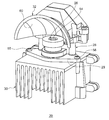
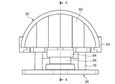
- FIG. 3 is a perspective view schematically showing an appearance of the light emitting unit 20 according to the embodiment.
- FIG. 4 is a perspective view schematically showing the appearance of the light source base 28 and the reflector 32 according to the embodiment. For easy understanding, the reflector 32 is hatched in FIG.
- the light source base 28 is directly attached to the heat sink 30 with the bottom plate 29 of the light source base 28 in contact with the upper surface of the heat sink 30.
- the light source base 28 is attached to the heat sink 30 using the light source base attachment screw 58, but any other attachment means may be used.
- the reflector 32 has a reflection surface 60 and is disposed outside (upward in the drawing) of the laser light source 26 so that the reflection surface 60 receives light from the light emitting surface 54.
- the reflecting surface 60 faces the light emitting surface 54.
- the reflector 32 is directly attached to the light source base 28. In the illustrated example, the reflector 32 is attached to the light source base 28 using the reflector attaching screw 62, but other arbitrary attaching means may be used.
- a fan (not shown) may be attached to the bottom of the heat sink 30.
- FIG. 5 is a perspective view schematically showing the appearance of the laser light source 26 and the light source base 28 according to the embodiment.
- the positioning surface is hatched in FIG. 6A is a schematic top view of the laser light source 26 and the light source base 28 according to the embodiment
- FIG. 6B is a schematic front view of the laser light source 26 and the light source base 28 according to the embodiment. is there.
- an orthogonal coordinate system having the light source center 57 as the origin is considered below. That is, the front-rear direction and the left-right direction of the lamp are the X axis and Y axis, respectively, and the optical axis direction is the Z axis.
- Light emitted from the laser light source 26 is directed forward in the X direction by the reflector 32.
- FIG. 6A the illustration of the hole through which the power supply terminal of the laser light source 26 is inserted is omitted for convenience.
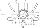
- FIG. 7 is a schematic bottom view of the reflector 32 according to the embodiment.
- FIG. 8 is a schematic front view of the light source base 28 and the reflector 32 according to the embodiment.
- 9 is a cross-sectional view taken along the line AA in FIG.
- the positioning structure 34 on the light source base 28 includes a cylindrical first positioning pin 64 and a columnar second positioning pin 66.
- the first positioning pin 64 and the second positioning pin 66 are erected on the bottom plate 29 of the light source base 28 and are integrally formed with the light source base 28.
- the light source base 28 is formed substantially symmetrical with respect to the X axis.
- the light source base 28 is a member that holds the laser light source 26 so that power can be supplied.
- a power supply substrate 68 for supplying power to the laser light source 26 is installed on the light source base 28.
- the center of the first positioning pin 64 coincides with the optical axis 56.
- the center of the second positioning pin 66 coincides with the center of the first positioning pin 64 in the Y direction. That is, the center of the first positioning pin 64 and the center of the second positioning pin 66 are both on the X axis.
- the second positioning pin 66 is disposed behind the first positioning pin 64 in the X direction.
- the first positioning pin 64 defines a first positioning side surface 70 centered on the optical axis 56.
- the first positioning side surface 70 corresponds to the outer peripheral surface of the first positioning pin 64.
- the first positioning side surface 70 is used to position the reflector 32 with respect to the laser light source 26 with respect to the rotation direction around the optical axis 56.
- the first positioning pin 64 defines the first positioning end surface 72.
- the first positioning end surface 72 corresponds to the upper surface of the first positioning pin 64 (that is, the tip surface in the optical axis direction).
- the first positioning end surface 72 is used for positioning the reflector 32 with respect to the laser light source 26 in the optical axis direction.
- the first positioning end surface 72 has a first height H1 in the optical axis direction from the bottom plate 29 of the light source base.
- the light emitting surface 54 has a second height H2 in the optical axis direction from the bottom plate 29 of the light source base 28.
- the second height H2 is higher than the first height H1.
- the light emitting surface 54 is located above the first positioning end surface 72.
- the first positioning pin 64 is formed with a light source mounting recess 74 on which the laser light source 26 is mounted. The most part of the laser light source 26 except the light emitting surface 54 and the vicinity thereof is accommodated in the light source mounting recess 74.
- the light source mounting recess 74 has a larger diameter than the laser light source 26, and there is a gap between the inner peripheral surface of the first positioning pin 64 and the outer peripheral surface of the laser light source 26. In this way, the first positioning pin 64 is formed so as to surround the laser light source 26.
- the second positioning pin 66 defines a second positioning side surface 76.
- the second positioning side surface 76 corresponds to the outer peripheral surface of the second positioning pin 66.
- the second positioning side surface 76 is used to position the reflector 32 with respect to the laser light source 26 with respect to the rotation direction around the optical axis 56.
- the outer diameter of the second positioning pin 66 is smaller than the outer diameter of the first positioning pin 64.
- the light source base 28 includes two reflector mounting screw holes 78. These reflector mounting screw holes 78 are arranged on both sides of the X axis. Each reflector mounting screw hole 78 is erected in a cylindrical shape on the bottom plate 29 of the light source base 28 and is integrally formed with the light source base 28. A screw hole for the reflector mounting screw 62 (see FIG. 4) is formed at the center of the reflector mounting screw hole portion 78.
- the reflector mounting screw hole 78 defines the second positioning end surface 80.
- the second positioning end surface 80 corresponds to the upper surface of the reflector mounting screw hole 78.
- the second positioning end face 80 is used for positioning the reflector 32 with respect to the laser light source 26 in the optical axis direction. Therefore, the second positioning end surface 80 is a part of the positioning structure 34.
- the second positioning end surface 80 is located at the same height as the first positioning end surface 72 in the optical axis direction.
- Two heat sink mounting screw holes 82 are formed in the bottom plate 29 of the light source base 28. These heat sink mounting screw holes 82 are arranged on both sides of the X axis. The heat sink mounting screw hole 82 is provided outside the reflector mounting screw hole 78 in the X direction. The light source base mounting screw 58 (see FIG. 3) is inserted into the heat sink mounting screw hole 82.
- the reflector 32 includes an engaging portion 84 that engages with the first positioning pin 64.
- the engaging portion 84 is a circular portion having an opening 85 for allowing the optical axis 56 to pass therethrough. That is, the light emitted from the light emitting surface 54 travels through the opening 85 toward the reflecting surface 60 of the reflector 32.
- the upper surface 89 of the engaging portion 84 is located at the same height as the light emitting surface 54 in the optical axis direction.
- the engaging portion 84 defines a first positioning hole 86 corresponding to the first positioning side surface 70 of the first positioning pin 64.
- the first positioning hole 86 corresponds to the inner peripheral surface of the engaging portion 84.
- the engaging portion 84 defines a first contact surface 88 that contacts the first positioning end surface 72 of the first positioning pin 64.
- the first contact surface 88 is a region between the opening 85 and the first positioning hole 86.
- the reflector 32 includes a reflector base portion 83 for supporting the reflector 32.
- the engaging portion 84 is a part of the reflector base portion 83.
- the reflector base 83 is coupled to the reflecting surface 60 of the reflector 32 at the rear in the X direction.
- the engaging portion 84 is disposed so as to cover the first positioning pin 64, the reflector base portion 83 can support the reflecting surface 60 of the reflector 32 above the laser light source 26.
- the reflector base portion 83 has a second positioning hole 90 that engages with the second positioning pin 66.
- the second positioning hole 90 is a long hole that is long in the X direction in which the second positioning pin 66 can be inserted.
- a mounting screw hole 92 corresponding to the reflector mounting screw hole 78 of the light source base 28 is formed in the reflector base 83.
- the reflector base 83 defines a second contact surface 94 that contacts the second positioning end surface 80 around the mounting screw hole 92.
- the light source base 28 By engaging the first positioning hole 86 and the second positioning hole 90 with the first positioning pin 64 and the second positioning pin 66, respectively, the light source base 28 causes the reflector 32 to move the reflector 32 with respect to the rotation direction around the optical axis 56. Can be positioned.
- the first contact surface 88 and the second contact surface 94 abut against the first positioning end surface 72 and the second positioning end surface 80, respectively, whereby the light source base 28 positions the reflector 32 with respect to the laser light source 26 in the optical axis direction. be able to.
- the positioning structure 34 for positioning the reflector 32 with respect to the laser light source 26 is provided on the light source base 28.
- both the laser light source 26 and the reflector 32 are supported by the light source base 28.
- the light source base 28 is attached to the heat sink 30. Therefore, the reflector 32 is directly fixed to the light source base 28 without using the heat sink 30.
- the accumulation of dimensional tolerances starting from the light source center 57 and starting from the diameter of the first positioning hole 86 of the reflector 32 is considered.
- This accumulation result reflects the variation in assembly accuracy between the optical components of the light emitting unit 20, that is, the optical axis accuracy. Since the reflector 32 is directly fixed to the light source base 28, the result of increasing the dimensional tolerance can be made relatively small. Accordingly, it is possible to provide the light emitting unit 20 with improved optical axis accuracy and the vehicular lamp 10 including the same.
- a light source base and a reflector are each attached to a heat sink.
- the reflector is attached to the light source base via a heat sink.
- the first positioning pin 64 defines a first positioning side surface 70 centered on the optical axis 56 of the laser light source 26. That is, the center of the first positioning pin 64 coincides with the light source center 57. With this design, the dimensional tolerance between the center of the first positioning pin 64 and the light source center 57 can be omitted when the product is stacked, thereby improving the optical axis accuracy.
- the center of the second positioning pin 66 coincides with the light source center 57 in the X direction. This also helps improve the optical axis accuracy.
- the first positioning pin 64 forms a light source mounting recess 74 on which the laser light source 26 is mounted, and the first positioning side surface 70 is an outer peripheral surface of the first positioning pin 64. Accordingly, the laser light source 26 and the first positioning pin 64 can be arranged coaxially, and the laser light source 26 can be accommodated in the light source mounting recess 74, so that the light source base 28 can be downsized.
- the first positioning pin 64 includes a first positioning end surface 72 positioned at a first height H1 in the optical axis direction, and the light emitting surface 54 is positioned at a second height H2 higher than the first height H1 in the optical axis direction. To do. Thus, the height of the front end surface of the first positioning pin 64 in the optical axis direction is lower than the light emitting surface 54 of the laser light source 26.
- the upper surface 89 of the engaging portion 84 of the reflector 32 can be disposed at the same height as the light emitting surface 54. Alternatively, the upper surface 89 of the engaging portion 84 of the reflector 32 can be disposed at a position lower than the height of the light emitting surface 54. Therefore, the engaging portion 84 does not block the light emitted from the light emitting surface 54 toward the reflector 32.
- FIG. 10 is a diagram schematically showing the internal structure of the vehicular lamp 110 according to the embodiment.
- the vehicular lamp 110 is a left-side vehicular headlamp provided at the left end portion of the front end portion of the vehicle body, and a right-side vehicular lamp having a mirror image with respect to the vehicular lamp 110 at the right end portion of the front end portion of the vehicle body. Headlights are arranged. Since the left vehicle headlamp and the right vehicle headlamp have the same structure, the left vehicle headlamp will be described below as an example.
- the vehicular lamp 110 includes a lamp body 112 having a concave portion opened forward, and a translucent cover 114 that closes the opening of the lamp body 112.
- the lamp body 112 and the cover 114 constitute a lamp housing 116.
- An internal space of the lamp housing 116 is formed as a lamp chamber 118.
- a light emitting unit 120 In the lamp chamber 118, a light emitting unit 120, an extension 122, and an optical member 124 are arranged.
- the optical member 124 is provided for condensing or narrowing the light emitted from the light emitting unit 120.
- the optical member 124 is, for example, a convex lens, a projection lens, a condensing lens, a light guide, a cylindrical lens, or the like.
- the light emitting unit 120 includes a laser light source 126, a light source base 128 that supports the laser light source 126, a heat dissipation member (hereinafter also referred to as a heat sink) 130 to which the light source base 128 is attached, and reflects light from the laser light source 126 to the front of the lamp. And a reflector 132.
- the light source base 128 is provided with a positioning structure 134 for positioning the reflector 132 with respect to the laser light source 126.
- the light emitting unit 120 includes a reflector tilting mechanism 136 provided on the light source base 128 so that the reflector 132 can tilt around two different axes with respect to the laser light source 126.
- the reflector 132 is attached to the light source base 128 and the heat sink 130 via a reflector tilting mechanism 136.
- the positioning structure 134 is also a part of the reflector tilting mechanism 136. Details of the light emitting unit 120, the positioning structure 134, and the reflector tilting mechanism 136 will be described later.
- the heat sink 130 is attached to a substantially central portion of the light emitting unit support member 140.
- the light emitting unit support member 140 may be a metal bracket, for example.
- a first aiming screw 142 is attached to the upper part of the light emitting unit support member 140, and a second aiming screw 144 is attached to the lower part of the light emitting unit support member 140.
- the light emitting unit support member 140 is supported by the lamp body 112 so as to be tiltable by the first aiming screw 142 and the second aiming screw 144.
- the light emitting unit support member 140 is tilted by rotating the first aiming screw 142 and the second aiming screw 144, and the light emitting unit 120 is tilted accordingly, and the optical axis adjustment (aiming adjustment) of the illumination light is performed. Is called.
- the vehicle lamp 110 may be provided with a plurality of light emitting units 120.
- the heat sinks 130 of the plurality of light emitting units 120 may be attached to a common light emitting unit support member 140. In this case, it is possible to adjust the optical axis of the light emitting unit 120 with respect to other light emitting units 120 using the reflector tilting mechanism 136 of a certain light emitting unit 120.
- the light emitting unit 120 may be provided for forming a high beam light distribution pattern.
- the vehicle lamp 110 may be provided with another light emitting unit for forming a low beam light distribution pattern.
- a reflector tilting mechanism 136 may be used to adjust the optical axis of the light emitting unit 120 relative to another light emitting unit. For example, the optical axis of the light emitting unit 120 may be adjusted with respect to the elbow point of the low beam light distribution pattern.
- FIG. 11 is a diagram schematically showing the internal structure of the laser light source 126 according to the embodiment.
- the laser light source 126 includes a laser diode 146 that is a kind of semiconductor light emitting element, a condensing lens 148 that condenses light emitted from the laser diode 146, a housing 150 that houses the laser diode 146 and the condensing lens 148, and And an optical wavelength converter 152 provided in a penetrating part formed in the upper part of the housing 150.
- the laser diode 146 is provided at the bottom of the housing 150.
- the laser diode 146 is formed by arranging one or a plurality of blue LDs.
- the light wavelength conversion unit 152 for example, a material in which a yellow phosphor is dispersed in a transparent sealing member, a plate-like yellow phosphor ceramic, or the like is used.
- the upper surface of the light wavelength conversion unit 152 becomes the light emission surface 154 of the laser light source 126.
- the optical axis 156 of the laser light source 126 is the strongest direction of the emitted light from the laser light source 126. Further, the optical axis 156 passes through the center of the light exit surface 154 and is perpendicular to the light exit surface 154. In this document, for convenience of explanation, the center of the light emitting surface 154 may be referred to as a light source center 157.
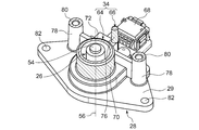
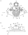
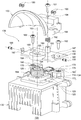
- FIG. 12 is a perspective view schematically showing an appearance of the light emitting unit 120 according to the embodiment.
- FIG. 13 is a schematic exploded perspective view of the light emitting unit 120 shown in FIG.
- the positioning surface is hatched in FIG.
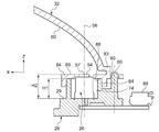
- FIG. 14 is a schematic cross-sectional view of the light emitting unit 120 shown in FIG.
- an orthogonal coordinate system having the light source center 157 as the origin is considered. That is, the front-rear direction and the left-right direction of the lamp are the X axis and Y axis, respectively, and the optical axis direction is the Z axis.
- Light emitted from the laser light source 126 is directed forward in the X direction by the reflector 132.
- FIG. 14 shows an XZ cross section.
- the reflector tilting mechanism 136 is configured such that the reflector 132 can tilt with respect to the laser light source 126 around the first tilting axis, and the reflector 132 can tilt with respect to the laser light source 126 around the second tilting axis 158. It is configured.
- the first tilt axis is the optical axis 156 of the laser light source 126.
- the second tilting axis 158 is orthogonal to the optical axis 156 and is located at the height of the light emitting surface 154 of the laser light source 126.
- the first tilt axis and the second tilt axis 158 correspond to the Z axis and the Y axis, respectively, and pass through the light source center 157.
- the light source base 128 is directly attached to the heat sink 130 with the bottom plate 129 of the light source base 128 in contact with the upper surface of the heat sink 130.
- the light source base 128 is attached to the heat sink 130 using screwing or any other attachment means.
- the light source base 128 and the heat sink 130 are formed substantially symmetrically with respect to the X axis.
- the heat sink 130 includes, for example, a boss portion 131 for fixing the heat sink 130 at a fixing place such as the light emitting unit support member 140 on the back side in the X direction.
- a fan (not shown) may be attached to the bottom of the heat sink 130.
- the positioning structure 134 on the light source base 128 includes a cylindrical positioning pin 164 having a center coinciding with the optical axis 156.
- the positioning pins 164 stand on the bottom plate 129 of the light source base 128 and are integrally formed with the light source base 128.
- the positioning pin 164 defines a cylindrical positioning side surface 170 centered on the optical axis 156.
- the positioning side surface 170 corresponds to the outer peripheral surface of the positioning pin 164.
- the positioning side 170 is used to position the reflector 132 relative to the laser light source 126 with respect to the direction of rotation about the optical axis 156.
- the positioning pin 164 defines the first positioning end surface 172.
- the first positioning end surface 172 corresponds to the upper surface of the positioning pin 164 (that is, the tip surface in the optical axis direction) and is on a plane perpendicular to the optical axis 156.
- the first positioning end surface 172 is used to position the reflector 132 with respect to the laser light source 126 with respect to the optical axis direction.
- the first positioning end surface 172 has a first height H1 from the bottom plate 129 of the light source base 128 in the optical axis direction.
- the light emitting surface 154 has a second height H2 from the bottom plate 129 of the light source base 128 in the optical axis direction.
- the second height H2 is higher than the first height H1.
- the light emitting surface 154 is located above the first positioning end surface 172.
- the positioning pin 164 has a light source mounting recess 174 on which the laser light source 126 is mounted. The most part of the laser light source 126 except the light emitting surface 154 and its vicinity is accommodated in the light source mounting recess 174.
- the light source mounting recess 174 has a larger diameter than the laser light source 126, and there is a gap between the inner peripheral surface of the positioning pin 164 and the outer peripheral surface of the laser light source 126.
- the positioning pin 164 is formed so as to surround the laser light source 126. Since the laser light source 126 and the positioning pin 164 are arranged coaxially and the laser light source 126 can be accommodated in the light source mounting recess 174, the light source base 128 can be reduced in size.
- the light source base 128 is a member that holds the laser light source 126 so that power can be supplied.
- the light source base 128 is provided with a power supply substrate 168 for supplying power to the laser light source 126.
- the heat sink 130 includes two reflector base mounting portions 178. These reflector base mounting portions 178 are disposed on both sides with the X axis interposed therebetween. The reflector base mounting portion 178 is disposed behind the positioning pin 164 in the X direction.
- the reflector base mounting portion 178 defines the second positioning end surface 180.
- the second positioning end surface 180 is formed so as to surround the screw hole 179 of the reflector base mounting portion 178.
- the second positioning end surface 180 is a part of the upper surface of the reflector base mounting portion 178 and is on a plane perpendicular to the optical axis 156.
- the second positioning end surface 180 is located at the same height as the first positioning end surface 172 in the optical axis direction. Since the reflector base mounting portion 178 is located behind the positioning pin 164 in the X direction, the second positioning end surface 180 is also located behind the positioning pin 164 in the X direction.
- the second positioning end surface 180 is used to position the reflector 132 with respect to the laser light source 126 with respect to the optical axis direction. Therefore, the second positioning end surface 180 is a part of the positioning structure 134.
- the reflector tilting mechanism 136 includes a reflector base 138 for supporting the reflector 132.
- a circular lid-like engaging portion 184 that engages with the positioning pin 164 is provided at the front center portion in the X direction of the reflector base 138.
- the reflector base 138 is a substantially rectangular flat plate member, and a semicircular portion in the front of the X direction of the engaging portion 184 protrudes forward in the X direction from the flat plate member.
- the upper surface 189 of the engaging portion 184 is located at the same height as the light emitting surface 154 in the optical axis direction.
- the engaging portion 184 has a cylindrical inner peripheral surface corresponding to the positioning side surface 170 of the positioning pin 164 and an annular flat surface corresponding to the first positioning end surface 172.
- the annular flat surface of the engaging portion 184 corresponds to the back surface opposite to the upper surface 189 of the engaging portion 184.
- the reflector base 138 has two arc-shaped groove portions 160 arranged corresponding to the two reflector base mounting portions 178, respectively.
- the two arc-shaped groove portions 160 are formed along the same arc centering on the light source center 157.
- the engaging portion 184 is disposed so as to cover the positioning pin 164, the outer peripheral portion of the arc-shaped groove portion 160 contacts the second positioning end surface 180 on the back surface side of the reflector base 138, and the arc-shaped groove portion 160 is attached to the reflector base.
- the screw hole 179 of the part 178 is communicated.
- the reflector base 138 and the reflector 132 supported by the reflector base 138 can be tilted around the optical axis 156 with respect to the laser light source 126.
- the reflector tilting mechanism 136 is provided on the light source base 128 so that the reflector 132 can tilt with respect to the laser light source 126 around the optical axis 156.
- the reflector base 138 is positioned in the optical axis direction by the first positioning end surface 172 and the second positioning end surface 180.
- the reflector base mounting screw 162 is inserted into the arc-shaped groove 160 from the upper surface side of the reflector base 138 and attached to the screw hole 179 of the reflector base mounting portion 178.
- the reflector base 138 is fixed to the light source base 128 and the heat sink 130.
- the number of reflector base mounting portions 178 and arc-shaped groove portions 160 is not limited to two.
- the reflector base attaching part 178 and the arc-shaped groove part 160 may be provided one by one or three or more.
- the engaging portion 184 has an opening 185 through which the optical axis 156 passes. That is, the light emitted from the light emission surface 154 of the laser light source 126 passes through the opening 185 and travels toward the reflector 132. The light reflected by the reflector 132 is directed forward in the X direction.
- the diameter B of the opening 185 is smaller than the diameter C of the laser light source 126. Thereby, it is possible to prevent the laser light source 126 from dropping out of the light source mounting recess 174 through the opening 185.
- the reflector base 138 supports the reflector 132 so that it can tilt around the second tilting shaft 158. Therefore, the reflector tilting mechanism 136 is configured to be able to adjust the distance between the two connecting portions 182 that connect the reflector 132 to the reflector base 138 so as to be tiltable around the second tilting shaft 158, and the reflector 132 and the reflector base 138. And an adjusting unit 183.
- the two connecting portions 182 are arranged on both sides of the X axis.
- Each connecting portion 182 includes a shaft 186 disposed on the second tilting shaft 158 and extending along the second tilting shaft 158, and thus the connecting portions 182 are located on both sides of the engaging portion 184.
- Each shaft 186 is inserted into the first shaft insertion hole 187 of the reflector base 138 and the second shaft insertion hole 188 of the reflector 132.
- a pair of E-rings 190 are attached to the shaft 186 so as to sandwich the first shaft insertion hole 187 and the second shaft insertion hole 188 through which the shaft 186 is inserted from both sides. In this way, each connecting portion 182 connects the reflector 132 to the reflector base 138 so that the reflector 132 can rotate around the shaft 186 with respect to the reflector base 138.
- the adjusting unit 183 is disposed at a position away from the second tilting shaft 158. As illustrated, the adjusting unit 183 connects the reflector 132 to the reflector base 138 behind the connecting unit 182 in the X direction.
- the adjustment unit 183 includes an adjustment screw 91, a spring 192, and an adjustment screw hole 193.
- the adjustment screw hole 193 is provided in the reflector base 138.
- the adjustment screw 91 is inserted into the adjustment screw insertion hole 194 of the reflector 132 in the optical axis direction and attached to the screw hole of the adjustment screw hole 193.
- the spring 192 is disposed between the reflector 132 and the reflector base 138 along the adjustment screw 91 so as to maintain the distance between the reflector 132 and the reflector base 138.
- Rotating the adjustment screw 91 adjusts the distance between the reflector 132 and the reflector base 138 in the optical axis direction. Since the reflector 132 is connected to the reflector base 138 by the connecting portion 182, the reflector 132 can be tilted around the second tilt shaft 158 with respect to the reflector base 138. In this way, the optical axis of the light emitting unit 120 can be adjusted in the Z direction (that is, the lamp vertical direction).
- the reflector tilting mechanism 136 that can tilt around two different axes is provided on the light source base 128 of the light emitting unit 120. Therefore, the angle of the reflector 132 with respect to the laser light source 126 can be adjusted for each of these two axes in a state where the light emitting unit 120 is attached to a predetermined place such as the light emitting unit support member 140. In this way, the optical axis of the light emitting unit 120 can be finely adjusted, and the optical axis accuracy of the light emitting unit 120 can be improved.
- the first tilt axis that is, the optical axis 156) and the second tilt axis 158 correspond to the Z axis and the Y axis, respectively, and pass through the light source center 157.
- the rotation center of the reflector tilting mechanism 136 coincides with the light source center 157. Therefore, the optical axis of the light emitting unit 120 can be adjusted while minimizing the influence on the light distribution.
- the positioning pin 164 defines a positioning side surface 170 centered on the optical axis 156 of the laser light source 126. That is, the center of the positioning pin 164 coincides with the light source center 157. With this design, it is possible to omit the dimensional tolerance between the center of the positioning pin 164 and the light source center 157 when considering the increase in dimensional tolerance. This also helps improve the optical axis accuracy.
- the positioning pin 164 includes a first positioning end surface 172 positioned at the first height H1 in the optical axis direction, and the light emitting surface 154 is positioned at the second height H2 higher than the first height H1 in the optical axis direction.
- the height of the front end surface in the optical axis direction of the positioning pin 164 is lower than the light emitting surface 154 of the laser light source 126.
- the upper surface 189 of the engaging portion 184 of the reflector 132 can be disposed at the same height as the light emitting surface 154.
- the upper surface 189 of the engaging portion 184 of the reflector 132 can be disposed at a position lower than the height of the light emitting surface 154. Therefore, the engaging portion 184 does not block the light emitted from the light emitting surface 154 toward the reflector 132.
- the laser light sources 26 and 126 have a cylindrical shape, but the shape of the light source is arbitrary.
- the laser light sources 26 and 126 may have a prismatic shape or other columnar shape, or may have a planar shape such as a substrate shape.
- the laser light sources 26 and 126 including the laser diodes 46 and 146 are used as the light sources, but the present invention is not limited to this.
- the light emitting units 20 and 120 may include a light source including other semiconductor light emitting elements such as a light emitting diode (LED (Light Emitting Diode)).
- LED Light Emitting Diode
- FIG. 15 is a diagram illustrating an LED light source 95 that can be employed in the light emitting units 20 and 120.
- the LED light source 95 includes a substrate 96, an LED chip 97 mounted on the substrate 96, and a fluorescent layer 98 provided on the LED chip 97.
- the LED chip 97 is formed, for example, by arranging one or a plurality of blue LEDs.
- the fluorescent layer 98 is made of, for example, a light wavelength conversion member such as a yellow phosphor dispersed in a transparent sealing member or a plate-like yellow phosphor ceramic.
- the upper surface of the fluorescent layer 98 is the light emitting surface 54.
- the optical axis 56 is the strongest direction of the emitted light from the LED light source 95.
- the optical axis 56 passes through the center of the light exit surface 54 (that is, the light source center 57) and is perpendicular to the light exit surface 54.
- the positioning structures 34 and 134 have cylindrical or columnar positioning pins, but the shape of the positioning pins is not limited to this.
- the positioning pin may have a rectangular tube shape, a prismatic shape, or any other shape.
- the positioning surface of the cylindrical positioning pin (for example, the first positioning pin 64 and the positioning pin 164) is not limited to the outer peripheral surface of the cylindrical positioning pin, and may be an inner peripheral surface.
- the engaging portion of the optical member (for example, the reflector 32 and the reflector base 138) may have an outer peripheral surface that engages with the inner peripheral surface of the cylindrical positioning pin.
- cylindrical positioning pins may not be continuous over the entire circumference in the circumferential direction around the optical axes 56 and 156.
- the cylindrical positioning pin may have one or a plurality of slits extending in the optical axis direction.
- the cylindrical positioning pins may be a plurality of protrusions arranged so as to surround the optical axes 56 and 156.
- the cylindrical positioning pin or positioning structure may be a cylindrical positioning pin or positioning structure having an arbitrary shape as long as the positioning surface can be defined.
- FIG. 16A is a schematic perspective view illustrating the first positioning pin 64 with a slit
- FIG. 16B is a diagram illustrating the conveyance of the laser light source 26.
- FIG. 16A shows the X axis, the Y axis, and the Z axis.
- the first positioning pin 64 is erected on the bottom plate 29 of the light source base 28 with the outer peripheral surface serving as the first positioning side surface 70.
- the first positioning pin 64 has a cylindrical shape and defines a light source mounting recess 74 inside.
- the first positioning pin 64 has three slits 64a.
- the slits 64a are provided at equal intervals in the circumferential direction.
- the first positioning pin 64 is divided into three protrusions arranged so as to surround the optical axis 56 by the three slits 64 a. Therefore, the first positioning end surface 72 is also divided into three by the slits 64a.
- the first positioning pin 64 has an annular base portion 64 b on the bottom plate 29 of the light source base 28, and three projections protrude from the base portion 64 b along the optical axis 56. Note that the first positioning pin 64 may not have the base portion 64 b, and three protrusions may protrude from the bottom plate 29 of the light source base 28.
- FIG. 16B shows a state where the laser light source 26 is carried by the mounting machine 99.
- the laser light source 26 is carried to the light source base 28 by the mounting machine 99 and is placed on the light source placement recess 74 in the first positioning pin 64.
- the mounting machine 99 has three chuck claws 99 a for gripping the laser light source 26. Since the three chuck claws 99a have an arrangement corresponding to the three slits 64a (that is, the three chuck claws 99a are arranged so as to surround the laser light source 26 at equal angular intervals), the laser light source The three chuck claws 99 a do not come into contact with the first positioning pins 64 when 26 is placed in the light source placement recess 74.
- the mounting machine 99 releases the chuck claw 99a. In this way, the mounting machine 99 can position the laser light source 26 in the Z direction with respect to the light source base 28 without the chuck claw 99a interfering with the first positioning pins 64.
- the laser light source 26 has a power supply terminal 26a at the bottom thereof.
- the light source base 28 has an insertion hole 29a through which the power supply terminal 26a of the laser light source 26 is inserted.
- the insertion hole 29 a penetrates from the light source mounting recess 74 to the back surface of the bottom plate 29 of the light source base 28.
- the power supply terminal 26a of the laser light source 26 is inserted into the insertion hole 29a.
- the power supply terminal 26 a of the laser light source 26 is connected to the power supply unit on the back side of the bottom plate 29 of the light source base 28.
- Such an insertion hole 29a may be similarly provided in the light source base 28 in the embodiment described with reference to FIGS.
- the number of chuck claws 99a of the mounting machine 99 is preferably three or more. It is desirable that the first positioning pins 64 have the same number of slits 64a as the chuck claws 99a. For example, when the mounting machine 99 has four chuck claws 99a, the first positioning pin 64 may have four slits 64a.
- the slit 64a may be provided on the positioning pin 164.
- the optical member positioned with respect to the light source by the positioning structure is not limited to the reflector 32.
- the optical member may be another optical member such as a lens.
- the optical member that can be tilted with respect to the light source by the tilting mechanism is not limited to the reflector 132.
- the optical member may be another optical member such as a lens.
- the light emitting unit 120 includes the light source base 128 as a light source support member, and the heat sink 130 is provided as a separate member from the light source base 128, but is not limited thereto.
- the light emitting unit may include a light source support member in which a light source base and a heat dissipation member are integrally formed.
- the positioning structure 34 may include a reflector tilting mechanism 136.
- the optical member positioning structure may include an optical member tilting mechanism configured to allow the optical member to tilt around two different axes with respect to the light source.
- the present invention can be used for a light emitting unit and a vehicle lamp.
Landscapes
- Engineering & Computer Science (AREA)
- General Engineering & Computer Science (AREA)
- Physics & Mathematics (AREA)
- Optics & Photonics (AREA)
- Mechanical Engineering (AREA)
- Microelectronics & Electronic Packaging (AREA)
- Non-Portable Lighting Devices Or Systems Thereof (AREA)
- Securing Globes, Refractors, Reflectors Or The Like (AREA)
Abstract
Priority Applications (4)
| Application Number | Priority Date | Filing Date | Title |
|---|---|---|---|
| EP17782282.2A EP3444525B1 (fr) | 2016-04-13 | 2017-04-05 | Unité émettrice de lumière et accessoire de lampe de véhicule |
| JP2018511972A JPWO2017179465A1 (ja) | 2016-04-13 | 2017-04-05 | 発光ユニットおよび車両用灯具 |
| CN201780023246.2A CN109073182B (zh) | 2016-04-13 | 2017-04-05 | 发光单元和车辆用灯具 |
| US16/156,804 US20190041020A1 (en) | 2016-04-13 | 2018-10-10 | Light-emitting unit and vehicle lamp |
Applications Claiming Priority (4)
| Application Number | Priority Date | Filing Date | Title |
|---|---|---|---|
| JP2016080337 | 2016-04-13 | ||
| JP2016-080337 | 2016-04-13 | ||
| JP2016-085829 | 2016-04-22 | ||
| JP2016085829 | 2016-04-22 |
Related Child Applications (1)
| Application Number | Title | Priority Date | Filing Date |
|---|---|---|---|
| US16/156,804 Continuation US20190041020A1 (en) | 2016-04-13 | 2018-10-10 | Light-emitting unit and vehicle lamp |
Publications (1)
| Publication Number | Publication Date |
|---|---|
| WO2017179465A1 true WO2017179465A1 (fr) | 2017-10-19 |
Family
ID=60041539
Family Applications (1)
| Application Number | Title | Priority Date | Filing Date |
|---|---|---|---|
| PCT/JP2017/014175 Ceased WO2017179465A1 (fr) | 2016-04-13 | 2017-04-05 | Unité émettrice de lumière et accessoire de lampe de véhicule |
Country Status (5)
| Country | Link |
|---|---|
| US (1) | US20190041020A1 (fr) |
| EP (1) | EP3444525B1 (fr) |
| JP (1) | JPWO2017179465A1 (fr) |
| CN (1) | CN109073182B (fr) |
| WO (1) | WO2017179465A1 (fr) |
Cited By (3)
| Publication number | Priority date | Publication date | Assignee | Title |
|---|---|---|---|---|
| JP2020053372A (ja) * | 2018-09-28 | 2020-04-02 | 日亜化学工業株式会社 | 発光装置の製造方法、発光モジュールの製造方法及び発光装置 |
| JP2022501782A (ja) * | 2018-09-28 | 2022-01-06 | ヴァレオ ビジョンValeo Vision | 可撓性部分及び剛性部分とともに位置決めピンを備える車両光モジュール |
| JP2024518937A (ja) * | 2021-05-07 | 2024-05-08 | ルミレッズ リミテッド ライアビリティ カンパニー | Ledモジュールのための二部品ヒートシンク |
Families Citing this family (2)
| Publication number | Priority date | Publication date | Assignee | Title |
|---|---|---|---|---|
| CN111365678B (zh) * | 2020-03-17 | 2025-04-11 | 苏州晶清光电科技有限公司 | 激光照明模组及调节方法 |
| JP7521363B2 (ja) * | 2020-09-30 | 2024-07-24 | 市光工業株式会社 | 車両用灯具システム |
Citations (3)
| Publication number | Priority date | Publication date | Assignee | Title |
|---|---|---|---|---|
| JP2008108613A (ja) * | 2006-10-26 | 2008-05-08 | Ichikoh Ind Ltd | 車両用灯具 |
| JP2010165536A (ja) * | 2009-01-15 | 2010-07-29 | Ichikoh Ind Ltd | 車両用灯具 |
| JP2015525952A (ja) * | 2012-07-11 | 2015-09-07 | チザラ リヒトシステーメ ゲーエムベーハーZizala Lichtsysteme GmbH | 自動車用照明装置 |
Family Cites Families (3)
| Publication number | Priority date | Publication date | Assignee | Title |
|---|---|---|---|---|
| CN201582652U (zh) * | 2009-09-04 | 2010-09-15 | 宁波安迪光电科技有限公司 | Led发光模组 |
| JP5071495B2 (ja) * | 2010-03-04 | 2012-11-14 | ウシオ電機株式会社 | 光源装置 |
| JP5666977B2 (ja) * | 2011-04-26 | 2015-02-12 | 株式会社小糸製作所 | 車両用灯具 |
-
2017
- 2017-04-05 WO PCT/JP2017/014175 patent/WO2017179465A1/fr not_active Ceased
- 2017-04-05 CN CN201780023246.2A patent/CN109073182B/zh not_active Expired - Fee Related
- 2017-04-05 JP JP2018511972A patent/JPWO2017179465A1/ja active Pending
- 2017-04-05 EP EP17782282.2A patent/EP3444525B1/fr not_active Not-in-force
-
2018
- 2018-10-10 US US16/156,804 patent/US20190041020A1/en not_active Abandoned
Patent Citations (3)
| Publication number | Priority date | Publication date | Assignee | Title |
|---|---|---|---|---|
| JP2008108613A (ja) * | 2006-10-26 | 2008-05-08 | Ichikoh Ind Ltd | 車両用灯具 |
| JP2010165536A (ja) * | 2009-01-15 | 2010-07-29 | Ichikoh Ind Ltd | 車両用灯具 |
| JP2015525952A (ja) * | 2012-07-11 | 2015-09-07 | チザラ リヒトシステーメ ゲーエムベーハーZizala Lichtsysteme GmbH | 自動車用照明装置 |
Cited By (8)
| Publication number | Priority date | Publication date | Assignee | Title |
|---|---|---|---|---|
| JP2020053372A (ja) * | 2018-09-28 | 2020-04-02 | 日亜化学工業株式会社 | 発光装置の製造方法、発光モジュールの製造方法及び発光装置 |
| JP2022501782A (ja) * | 2018-09-28 | 2022-01-06 | ヴァレオ ビジョンValeo Vision | 可撓性部分及び剛性部分とともに位置決めピンを備える車両光モジュール |
| JP7179168B2 (ja) | 2018-09-28 | 2022-11-28 | ヴァレオ ビジョン | 可撓性部分及び剛性部分とともに位置決めピンを備える車両光モジュール |
| US11668446B2 (en) | 2018-09-28 | 2023-06-06 | Valeo Vision | Vehicle light module comprising a locating pin with a flexible part and a rigid part |
| JP7288173B2 (ja) | 2018-09-28 | 2023-06-07 | 日亜化学工業株式会社 | 発光装置の製造方法、発光モジュールの製造方法及び発光装置 |
| US12044399B2 (en) | 2018-09-28 | 2024-07-23 | Nichia Corporation | Method of manufacturing light-emitting device, method of manufacturing light emitting module, and light-emitting device |
| JP2024518937A (ja) * | 2021-05-07 | 2024-05-08 | ルミレッズ リミテッド ライアビリティ カンパニー | Ledモジュールのための二部品ヒートシンク |
| JP7583190B2 (ja) | 2021-05-07 | 2024-11-13 | ルミレッズ リミテッド ライアビリティ カンパニー | Ledモジュールのための二部品ヒートシンク |
Also Published As
| Publication number | Publication date |
|---|---|
| US20190041020A1 (en) | 2019-02-07 |
| CN109073182B (zh) | 2021-05-25 |
| CN109073182A (zh) | 2018-12-21 |
| JPWO2017179465A1 (ja) | 2019-02-21 |
| EP3444525B1 (fr) | 2020-10-07 |
| EP3444525A4 (fr) | 2019-11-06 |
| EP3444525A1 (fr) | 2019-02-20 |
Similar Documents
| Publication | Publication Date | Title |
|---|---|---|
| JP4500273B2 (ja) | 車両用前照灯 | |
| CN101553688B (zh) | 用于车辆前灯的照明单元以及车辆前灯 | |
| CN102667322B (zh) | 用于照明装置的反射器和照明装置 | |
| US10094526B2 (en) | Vehicle lamp | |
| US20100208483A1 (en) | Vehicle lighting system | |
| WO2017179465A1 (fr) | Unité émettrice de lumière et accessoire de lampe de véhicule | |
| CN115066581B (zh) | 灯具单元 | |
| US9551478B2 (en) | Lighting device | |
| CN211821815U (zh) | 灯具单元 | |
| JP5332688B2 (ja) | 車両用灯具 | |
| JP2020064872A (ja) | 発光装置及び発光システム | |
| JP5749837B2 (ja) | 光源固定用アタッチメント | |
| US20240288139A1 (en) | Vehicle lamp fitting | |
| JP3212842U (ja) | 照明装置 | |
| JP7151317B2 (ja) | 照明装置 | |
| JP6241599B2 (ja) | 照明装置 | |
| JP2004182071A (ja) | 照明用灯具 | |
| JP7302287B2 (ja) | 車両用灯具 | |
| JP2020167124A (ja) | 照明装置 | |
| JP2004185970A (ja) | 照明用灯具 | |
| JP7099900B2 (ja) | 車両用灯具 | |
| JP6340753B2 (ja) | 発光装置 | |
| JP2026055532A (ja) | 車輌用灯具 | |
| JP2024124745A (ja) | 車輌用前照灯 | |
| JP6217184B2 (ja) | 発光装置 |
Legal Events
| Date | Code | Title | Description |
|---|---|---|---|
| WWE | Wipo information: entry into national phase |
Ref document number: 2018511972 Country of ref document: JP |
|
| NENP | Non-entry into the national phase |
Ref country code: DE |
|
| WWE | Wipo information: entry into national phase |
Ref document number: 2017782282 Country of ref document: EP |
|
| ENP | Entry into the national phase |
Ref document number: 2017782282 Country of ref document: EP Effective date: 20181113 |
|
| 121 | Ep: the epo has been informed by wipo that ep was designated in this application |
Ref document number: 17782282 Country of ref document: EP Kind code of ref document: A1 |