WO2017179487A1 - 光ファイバ保護構造及びこれを用いた光コンバイナ構造 - Google Patents
光ファイバ保護構造及びこれを用いた光コンバイナ構造 Download PDFInfo
- Publication number
- WO2017179487A1 WO2017179487A1 PCT/JP2017/014389 JP2017014389W WO2017179487A1 WO 2017179487 A1 WO2017179487 A1 WO 2017179487A1 JP 2017014389 W JP2017014389 W JP 2017014389W WO 2017179487 A1 WO2017179487 A1 WO 2017179487A1
- Authority
- WO
- WIPO (PCT)
- Prior art keywords
- resin
- optical fiber
- fiber
- optical
- protection structure
- Prior art date
- Legal status (The legal status is an assumption and is not a legal conclusion. Google has not performed a legal analysis and makes no representation as to the accuracy of the status listed.)
- Ceased
Links
Images








Classifications
-
- G—PHYSICS
- G02—OPTICS
- G02B—OPTICAL ELEMENTS, SYSTEMS OR APPARATUS
- G02B6/00—Light guides; Structural details of arrangements comprising light guides and other optical elements, e.g. couplings
- G02B6/24—Coupling light guides
- G02B6/255—Splicing of light guides, e.g. by fusion or bonding
- G02B6/2558—Reinforcement of splice joint
-
- G—PHYSICS
- G02—OPTICS
- G02B—OPTICAL ELEMENTS, SYSTEMS OR APPARATUS
- G02B6/00—Light guides; Structural details of arrangements comprising light guides and other optical elements, e.g. couplings
- G02B6/24—Coupling light guides
- G02B6/255—Splicing of light guides, e.g. by fusion or bonding
-
- G—PHYSICS
- G02—OPTICS
- G02B—OPTICAL ELEMENTS, SYSTEMS OR APPARATUS
- G02B6/00—Light guides; Structural details of arrangements comprising light guides and other optical elements, e.g. couplings
- G02B6/24—Coupling light guides
- G02B6/26—Optical coupling means
-
- G—PHYSICS
- G02—OPTICS
- G02B—OPTICAL ELEMENTS, SYSTEMS OR APPARATUS
- G02B6/00—Light guides; Structural details of arrangements comprising light guides and other optical elements, e.g. couplings
- G02B6/44—Mechanical structures for providing tensile strength and external protection for fibres, e.g. optical transmission cables
- G02B6/4401—Optical cables
- G02B6/4429—Means specially adapted for strengthening or protecting the cables
- G02B6/443—Protective covering
- G02B6/4432—Protective covering with fibre reinforcements
-
- G—PHYSICS
- G02—OPTICS
- G02B—OPTICAL ELEMENTS, SYSTEMS OR APPARATUS
- G02B6/00—Light guides; Structural details of arrangements comprising light guides and other optical elements, e.g. couplings
- G02B6/24—Coupling light guides
- G02B6/255—Splicing of light guides, e.g. by fusion or bonding
- G02B6/2551—Splicing of light guides, e.g. by fusion or bonding using thermal methods, e.g. fusion welding by arc discharge, laser beam, plasma torch
-
- G—PHYSICS
- G02—OPTICS
- G02B—OPTICAL ELEMENTS, SYSTEMS OR APPARATUS
- G02B6/00—Light guides; Structural details of arrangements comprising light guides and other optical elements, e.g. couplings
- G02B6/24—Coupling light guides
- G02B6/36—Mechanical coupling means
- G02B6/3628—Mechanical coupling means for mounting fibres to supporting carriers
- G02B6/3632—Mechanical coupling means for mounting fibres to supporting carriers characterised by the cross-sectional shape of the mechanical coupling means
- G02B6/3636—Mechanical coupling means for mounting fibres to supporting carriers characterised by the cross-sectional shape of the mechanical coupling means the mechanical coupling means being grooves
Definitions
- the present invention relates to an optical fiber protection structure, and more particularly to an optical fiber protection structure in which at least a part of an optical fiber is accommodated.
- the portion where the optical fiber coating is removed in this way is It is weak against external force and may break when subjected to impact or vibration. For this reason, the portion where the coating of the optical fiber such as the fusion point is removed is accommodated in a fiber accommodating portion made of a material having a high tensile strength and fixed with a resin or the like.
- FIG. 1 is a front view schematically showing such a conventional optical fiber protection structure 800
- FIG. 2 is a cross-sectional view taken along line AA in FIG. 1
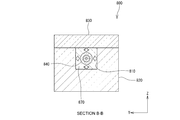
- FIG. 3 is a cross-sectional view taken along line BB in FIG.
- the conventional optical fiber protection structure 800 includes a fiber housing portion 820 in which a groove 810 is formed, and a lid portion 830 placed on the fiber housing portion 820.
- the groove 810 of the optical fiber protection structure 800 accommodates the portion from which the coating of the two optical fibers 840 and 840 is removed and the fused portion 860.
- the optical fibers 840 and 840 are fixed to the fiber housing portion 820 with resin 870 at both ends of the groove 810.
- a lid portion 830 is fixed on the fiber accommodating portion 820.
- the fiber accommodating portion 820 and the lid portion 830 are formed from a material having high tensile strength.
- the present invention has been made in view of such problems of the prior art, and provides an optical fiber protection structure capable of suppressing an increase in optical loss of an optical fiber under a high temperature environment or a high humidity environment. Is the first purpose.
- the second object of the present invention is to provide an optical combiner structure in which light loss is unlikely to increase even in a high temperature environment or a high humidity environment.
- an optical fiber protection structure capable of suppressing an increase in optical loss of an optical fiber under a high temperature environment or a high humidity environment.
- This optical fiber protection structure includes a fiber housing portion in which a fiber housing groove for housing at least a part of at least one optical fiber is formed, and a first resin filled in the fiber housing groove. The first resin fixes at least a part of the at least one optical fiber in the fiber accommodation groove.
- the optical fiber protection structure includes a lid portion disposed on the fiber housing portion so as to cover at least a part of the fiber housing groove, a fixing portion for fixing the lid portion on the fiber housing portion, and the lid A first stress relieving part that allows expansion of the first resin toward the part and relieves stress acting on the at least one optical fiber.
- the first stress relaxation portion closes the lid. Since the first resin is allowed to expand toward the portion, the stress acting on the optical fiber from the first resin is relieved. Therefore, it is possible to effectively suppress an increase in optical loss due to the stress acting on the optical fiber.
- the first stress relaxation portion is a second resin formed between the first resin and the lid portion, and is configured by a second resin having a Young's modulus lower than that of the first resin. May be.
- the first stress relaxation part may be configured by a gap formed between the first resin and the lid part.
- the fixing portion may be made of a third resin formed between the upper surface of the fiber housing portion and the lid portion.
- the Young's modulus of the third resin is higher than the Young's modulus of the second resin.
- the third resin having a higher Young's modulus than the second resin is used to fix the lid on the fiber housing portion, so that the second resin having a relatively low Young's modulus (easily deformable) can be used for the optical fiber.
- the lid portion can be firmly fixed on the fiber housing portion by the third resin having a relatively high Young's modulus (not easily deformed) while relaxing the stress acting on the fiber.
- the second resin is formed between the first resin and the lid portion and between the upper surface of the fiber housing portion and the lid portion, and has a Young's modulus higher than that of the first resin.
- the optical fiber protection structure includes a fourth resin provided in the fiber housing groove so as to cover at least a part of the at least one optical fiber in the fiber housing groove, and the fourth resin toward the lid. And a second stress relaxation part that allows the resin to expand and relieves stress acting on the at least one optical fiber.
- the fourth resin may be formed of a material having a refractive index lower than that of the cladding of the optical fiber. With such a configuration, it is possible to prevent the light guided through the exposed wire portion from leaking to the outside.
- the fourth resin may be formed of a material having a higher refractive index than the cladding of the optical fiber. In this case, it is possible to reduce the influence of the heat generated by the unnecessary light on the optical fiber while removing the unnecessary light propagating through the cladding of the optical fiber.
- the second stress relaxation part is a fifth resin formed between the fourth resin and the lid part, and is constituted by a fifth resin having a Young's modulus lower than that of the fourth resin. May be.
- the second stress relaxation part may be constituted by a gap formed between the fourth resin and the lid part. With such a configuration, the fourth resin is allowed to expand toward the lid, so that the stress acting on the optical fiber is relieved.
- an optical combiner structure in which light loss hardly increases even in a high temperature environment or a high humidity environment.
- the optical combiner structure includes the optical fiber protection structure, the first optical fiber, the second optical fiber, and a fusion part obtained by fusing the first optical fiber and the second optical fiber. And an optical combiner.
- the fiber housing groove of the fiber housing part in the optical fiber protection structure at least a part of the first optical fiber, at least a part of the second optical fiber, and the fusion part of the optical combiner. Is housed.
- the first stress-relaxing portion covers the lid. Since the first resin is allowed to expand toward the portion, the stress acting on the optical fiber from the first resin is relieved. Accordingly, an increase in optical loss of the optical fiber due to stress acting on the optical fiber is effectively suppressed.
- FIG. 1 is a front view showing a conventional optical fiber protection structure.
- 2 is a cross-sectional view taken along line AA in FIG. 3 is a cross-sectional view taken along line BB in FIG.
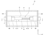
- FIG. 4 is a front view showing the optical combiner structure according to the first embodiment of the present invention.
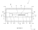
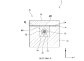
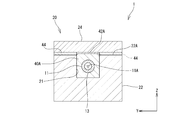
- FIG. 5 is a cross-sectional view taken along the line CC of FIG. 6 is a cross-sectional view taken along the line DD of FIG. 7 is a cross-sectional view taken along the line EE of FIG. 8 is a cross-sectional view taken along line FF in FIG.
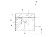
- FIG. 9 is a cross-sectional view showing a state where the first resin has expanded in the optical combiner structure shown in FIG. FIG.
- FIG. 10 is a cross-sectional view showing an optical combiner structure according to the second embodiment of the present invention, and corresponds to the cross-sectional view of FIG.
- FIG. 11 is a cross-sectional view showing an optical combiner structure according to the second embodiment of the present invention, and corresponds to the cross-sectional view of FIG.
- FIG. 12 is a cross-sectional view showing an optical combiner structure according to the third embodiment of the present invention, and corresponds to the cross-sectional view of FIG.
- FIG. 13 is a sectional view showing an optical combiner structure according to the fourth embodiment of the present invention, and corresponds to the sectional view of FIG. FIG.
- FIG. 14 is a cross-sectional view showing an optical combiner structure according to the fourth embodiment of the present invention, and corresponds to the cross-sectional view of FIG.
- FIG. 15 is a cross-sectional view showing an optical combiner structure according to the fifth embodiment of the present invention, and corresponds to the cross-sectional view of FIG.
- FIG. 16 is a cross-sectional view showing a state where the first resin has expanded in the optical combiner structure shown in FIG.
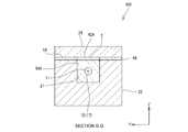
- FIG. 17 is a sectional view showing an optical combiner structure according to the sixth embodiment of the present invention, and corresponds to the sectional view of FIG. 18 is a cross-sectional view taken along the line GG of FIG.
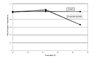
- FIG. 19 is a graph showing the relationship between the temperature and the rate of change in transmittance in an example and a comparative example of an optical fiber protection structure according to the present invention.
- FIGS. 4 to 19 the same or corresponding components are denoted by the same reference numerals, and redundant description is omitted. Further, in FIGS. 4 to 19, the scales and dimensions of the respective constituent elements are exaggerated and some constituent elements may be omitted.
- FIG. 4 is a front view showing the optical combiner structure 1 in the first embodiment of the present invention
- FIG. 5 is a cross-sectional view taken along the line CC of FIG.
- the optical combiner structure 1 includes an optical combiner 10 including optical fibers 11 and 12 fused to each other, and an optical fiber protection structure that protects a fused portion 19 of the optical fibers 11 and 12. 20 and so on.
- the optical combiner 10 includes a first optical fiber 11, a second optical fiber 12, and a fusion part 19 in which the first optical fiber 11 and the second optical fiber 12 are fused to each other.
- the optical fiber protection structure 20 protects the optical fibers 11 and 12 and the fused portion 19 from external force, impact, and vibration.
- the optical fiber protection structure 20 includes a fiber housing portion 22 in which a fiber housing groove 21 is formed on the upper surface 22A along the X direction, and a lid portion 24 disposed on the fiber housing portion 22.
- the fiber housing portion 22 has a substantially rectangular parallelepiped outer shape with the X direction as the longitudinal direction, and the lid portion 24 is configured to have substantially the same dimensions as the fiber housing portion 22 in plan view.
- the coating 13 of the first optical fiber 11 is peeled off from the end portion over a certain distance, thereby forming a strand exposed portion 17 where the strand 15 is exposed.
- the coating 14 of the second optical fiber 12 is peeled off from the end portion over a certain distance, thereby forming a strand exposed portion 18 where the strand 16 is exposed.
- the strand exposed portion 17 of the first optical fiber 11 and the strand exposed portion 18 of the second optical fiber 12 are fused and connected to each other at a fused portion 19.
- the strand exposed portion 17 of the first optical fiber 11 and the strand exposed portion 18 of the second optical fiber 12 are fused in the fused portion 19. Be placed.
- the fused portion 19 and the exposed wire portions 17 and 18 are covered with the fiber accommodating portion 22 and the lid portion 24, and these are external force, impact, and Protected from vibration.
- the fiber accommodating part 22 and the cover part 24 can be formed, for example from glass materials, such as Neoceram (trademark) and quartz.
- the first optical fiber 11 is constituted by a single fiber having a core 11A (see FIG. 6), and the second optical fiber 12 is a plurality of optical fibers having a core 12A (example shown in the figure). Then, seven optical fibers) are bundled to form a bundle fiber (see FIG. 7).
- the optical combiner 10 of this embodiment is configured as a 7 ⁇ 1 optical combiner. Needless to say, the number of cores 11A of the first optical fiber 11 and the number of cores 12A of the second optical fiber 12 can be changed as appropriate.
- the first optical fiber 11 is fixed in the fiber accommodation groove 21 by the first resin 40 ⁇ / b> A filled in one end of the fiber accommodation groove 21 in the X direction.
- the first resin 40 ⁇ / b> A surrounds the entire outer periphery of the coating 13 of the first optical fiber 11.
- the second optical fiber 12 is placed in the fiber accommodation groove 21 by the first resin 40 ⁇ / b> B filled in the other end portion in the X direction of the fiber accommodation groove 21. It is fixed.
- the first resin 40B also surrounds the entire outer periphery of the coating 14 of the second optical fiber 12, as shown in FIG.
- a second resin 42A is formed between the first resin 40A and the lid 24, and the first resin 40A and the lid are formed by the second resin 42A. 24 are connected to each other.
- a second resin 42B is formed between the first resin 40B and the lid 24, and the first resin 40B is formed by the second resin 42B.
- the second resins 42A and 42B are made of a material having a Young's modulus lower than that of the first resins 40A and 40B.
- a third resin 44 is formed.
- the fiber housing portion 22 and the lid portion 24 are fixed to each other mainly by the third resin 44. Therefore, in the present embodiment, the third resin 44 serves as a fixing portion that fixes the lid portion 24 on the fiber accommodating portion 22.
- an RTV (Room Temperature Vulcanizing) resin or the like can be used as such third resin 44.
- the second resin 42A, 42B and the third resin 44 are formed over the entire periphery at the edge of the upper surface 22A of the fiber accommodating portion 22, and the lid portion 24 is placed on these resins. ing. Therefore, the lid portion 24 can be fixed in a state of being in close contact with the fiber housing portion 22, and a sealed space S that is substantially sealed from the outside can be formed inside the fiber housing portion 22.
- the air in the sealed space S forms an air cladding for the exposed wire portions 17 and 18 of the optical fibers 11 and 12.
- the exposed wire portions 17 and 18 and the fused portion 19 of the optical fibers 11 and 12 are accommodated in the fiber accommodation groove 21 of the fiber accommodation portion 22 and surrounded by the fiber accommodation portion 22 and the lid portion 24. . Therefore, the exposed wire portions 17 and 18 and the fused portion 19 of the optical fibers 11 and 12 that are particularly susceptible to external force are protected from external force, impact, and vibration. Moreover, since the exposed wire portions 17 and 18 of the optical fibers 11 and 12 are disposed in the sealed space S, it is possible to prevent foreign matters such as dust from adhering to the exposed wire portions 17 and 18. Therefore, it is possible to prevent the light in the optical fibers 11 and 12 from leaking to the adhered foreign material and causing the optical fiber to burn out.
- the first resins 40A and 40B for fixing the optical fibers 11 and 12 to the fiber housing groove 21 are formed. Inflate.
- second resins 42A and 42B having a Young's modulus lower than that of the first resins 40A and 40B (that is, easily deformed) are formed between the first resins 40A and 40B and the lid portion 24.
- the first resins 40A and 40B are expanded in a high-temperature environment or a high-humidity environment, the first resins 40A and 42B are deformed and the first resin 40A and 40B is deformed toward the lid portion 24. Expansion of the resins 40A and 40B is allowed. Thereby, since the stress which acts on the optical fibers 11 and 12 from the 1st resin 40A, 40B is relieved, the increase in the optical loss of the optical fibers 11 and 12 is suppressed.
- the second resins 42A and 42B in the present embodiment allow the first resin 40A and 40B to expand toward the lid portion 24, thereby relaxing the stress acting on the optical fibers 11 and 12. It functions as a part.
- the Young's modulus of the third resin 44 as a fixing portion for fixing the lid portion 24 on the fiber accommodating portion 22 is higher than the Young's modulus of the second resins 42A and 42B.
- the third resin 44 having a higher Young's modulus than the second resins 42A and 42B is fixed on the fiber housing portion 22 by the third resin 44, whereby the second resin having a relatively low Young's modulus (easily deformed).
- the lid 24 is firmly fixed on the fiber accommodating portion 22 by the third resin having a relatively high Young's modulus (not easily deformed). Can be fixed.
- the first resin 40A, 40B and the second resin 42A, 42B are formed at both ends of the fiber accommodation groove 21, but the first resin 40A, 40B and the second resin 42A. , 42B can be formed shifted from the end of the fiber receiving groove 21 toward the center in the X direction.
- the place which forms 1st resin 40A, 40B and 2nd resin 42A, 42B is not restricted to 2 places, One place may be sufficient, and 3 places or more may be sufficient.
- FIG. 10 and 11 are cross-sectional views showing an optical combiner structure 101 according to the second embodiment of the present invention.
- FIG. 10 corresponds to the cross-sectional view of FIG. 5
- FIG. 11 is a cross-sectional view of FIG. It corresponds to.
- the widths of the second resins 42A and 42B along the Y direction are substantially the same as the widths of the first resins 40A and 40B along the Y direction.
- the widths of the second resins 142A and 142B along the Y direction are longer than the widths of the first resins 40A and 40B along the Y direction.
- the second resins 142 ⁇ / b> A and 142 ⁇ / b> B are formed over the entire width along the Y direction of the fiber housing portion 22. According to such a configuration, since the region of the second resin 142A, 142B that allows expansion of the first resin 40A, 40B is wider than that in the first embodiment, the stress acting on the optical fibers 11, 12 is increased. Can be reduced more effectively.
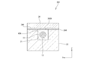
- FIG. 12 is a diagram showing an optical combiner structure 201 according to the third embodiment of the present invention, and corresponds to the cross-sectional view of FIG.
- the widths of the second resins 242A and 242B along the Y direction are made smaller than the widths of the first resins 40A and 40B along the Y direction. .
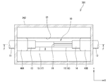
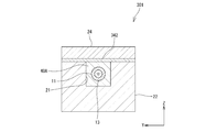
- FIGS. 13 and 14 are cross-sectional views showing an optical combiner structure 301 according to the fourth embodiment of the present invention.
- FIG. 13 corresponds to the cross-sectional view of FIG. 5
- FIG. 14 is a cross-sectional view of FIG. It corresponds to.
- the second resin made of a material having a Young's modulus lower than that of the first resins 40A and 40B between the first resins 40A and 40B and the lid portion 24.
- a resin 342 is formed, and the second resin 342 is formed not only between the first resins 40A and 40B and the lid portion 24 but also along the edge of the fiber accommodating portion 22.
- the second resin 342 in the present embodiment is a stress relieving part that relieves stress acting on the optical fibers 11 and 12 by allowing the first resins 40A and 40B to expand toward the lid part 24.
- it functions as a fixing portion for fixing the lid portion 24 on the fiber accommodating portion 22. According to this embodiment, since the stress relaxation portion and the fixed portion can be realized by the same resin, the manufacturing process can be simplified and the manufacturing cost can be suppressed.
- FIG. 15 is a sectional view showing an optical combiner structure 401 in the fifth embodiment of the present invention, and corresponds to the sectional view of FIG.
- a gap G is formed between the first resin 40 ⁇ / b> A and the lid portion 24.
- the first resin 40A expands as shown in FIG. 16, but the first resin 40A and the lid 24 Since the gap G is formed between the first resin 40 ⁇ / b> A and the first resin 40 ⁇ / b> A, the first resin 40 ⁇ / b> A is allowed to expand.
- the gap G formed between the first resin 40A and the lid portion 24 acts on the optical fiber 11 while allowing the first resin 40A to expand toward the lid portion 24. It functions as a stress relaxation part that relieves stress.
- FIG. 17 is a cross-sectional view showing an optical combiner structure 501 in the sixth embodiment of the present invention, and is a cross-sectional view corresponding to FIG. 18 is a cross-sectional view taken along the line GG of FIG.
- the sealed space S is filled with resin.
- first resins 40A and 40B are provided at both ends in the X direction of the fiber accommodating groove 21 of the optical combiner structure 501, and the first resin 40A and the first resin 40B are the same as in the first embodiment.
- Second resins 42A and 42B are provided between the resins 40A and 40B and the lid 24.
- the fiber receiving groove 21 includes the fourth resin so as to surround the entire circumference of the optical fibers 11 and 12 except for the portions where the first resins 40A and 40B are provided.
- the resin 546 is filled.
- the fourth resin 546 is formed of a material having a refractive index lower than that of the cladding of the strands 15 and 16, and a gap T is formed between the fourth resin 546 and the lid portion 24.
- the fourth resin 546 formed of a material having a refractive index lower than that of the cladding of the strands 15 and 16, the strands are exposed. The light guided through the parts 17 and 18 is prevented from leaking to the outside.
- a gap T is formed between the fourth resin 546 and the lid 24, even if the fourth resin 546 expands in a high temperature environment or a high humidity environment, the gap T is formed. T allows the fourth resin 546 to expand toward the lid 24, and the stress acting on the optical fibers 11 and 12 is relieved.
- the gap T acts as a stress relaxation portion that allows the fourth resin 546 to expand toward the lid portion 24 and relaxes the stress acting on the optical fibers 11 and 12. Therefore, an increase in optical loss of the optical fibers 11 and 12 under a high temperature environment or a high humidity environment is suppressed.
- a fifth resin (not shown) having a Young's modulus lower than that of the fourth resin 546 is provided between the fourth resin 546 and the lid portion 24 instead of or in addition to the gap T. You may form as a stress relaxation part.
- the Young's modulus of the second resins 42A and 42B is lower than the Young's modulus of the fourth resin, the second resins 42A and 42B can be used as such a fifth resin.
- the fourth resin 546 may be formed of a material having a lower refractive index than that of the coatings 13 and 14 in order to reduce leakage of light from the coatings 13 and 14. Furthermore, in order to suppress an increase in manufacturing cost, the first resin 40A, 40B and the fourth resin 546 may be formed of the same material. Further, the fourth resin 546 may be provided so as to cover only a part of the exposed wire portions 17 and 18.
- the fourth resin 546 is formed of a material having a refractive index lower than that of the cladding of the strands 15 and 16, but an optical fiber having a core and at least one cladding.
- a fourth resin may be formed of a material having a higher refractive index than that of the clad, and the fourth resin may be provided in the vicinity of the fused portion 19.
- the dimensions of the fiber accommodating portion 22 and the lid portion 24 in plan view are the same, and the lid portion 24 is disposed on the fiber accommodating portion 22 so as to cover the entire length of the fiber accommodating groove 21.
- the part 24 does not need to cover the entire length of the fiber accommodation groove 21, and may be configured to cover at least a part of the fiber accommodation groove 21.
- the fiber housing portion 22 and the lid portion 24 may be fixed using mechanical means such as bolts, or the fiber housing portion 22 and the lid portion 24 may be fixed using magnetism.
- means such as making the weight of the lid 24 heavier than that of the fiber housing 22 so that a large frictional force acts between the fiber housing 22 and the lid 24 can be adopted.
- the optical combiner structure using the optical fiber protection structure according to the present invention has been described as an example.
- the optical fiber protection structure according to the present invention can be applied to optical elements other than the optical combiner. Needless to say.
- the optical fiber protection structure shown in FIGS. 10 and 11 is used, and the optical fiber structure is placed in a temperature environment from 25 ° C. to 70 ° C. for light.
- the optical transmittance of the fiber was measured.
- a similar experiment was performed on an RTV resin having a Young's modulus higher than that of the first resin 40A instead of the second resin 342 in the optical fiber protection structure shown in FIGS. The optical transmittance of the optical fiber was measured.
- FIG. 19 is a graph showing the change rate of the light transmittance at each temperature when the light transmittance at 25 ° C. is 1.
- the light transmittance of the embodiment of the optical fiber protection structure according to the present invention is represented by a solid line
- the light transmittance of the comparative example is represented by a broken line.
- the light transmittance in the example of the optical fiber protection structure according to the present invention, the light transmittance hardly changes with respect to the temperature change from 25 ° C. to 70 ° C., but in the comparative example, the light transmission at 70 ° C. It can be seen that the transmittance is greatly reduced. From this, it has been found that the optical fiber protection structure according to the present invention is less likely to reduce the light transmittance even in a high temperature environment as compared with the optical fiber protection structure of the comparative example.
- the present invention is suitably used for an optical combiner having an optical fiber protection structure in which at least a part of an optical fiber is accommodated.
Landscapes
- Physics & Mathematics (AREA)
- General Physics & Mathematics (AREA)
- Optics & Photonics (AREA)
- Engineering & Computer Science (AREA)
- Plasma & Fusion (AREA)
- Mechanical Coupling Of Light Guides (AREA)
- Light Guides In General And Applications Therefor (AREA)
- Road Signs Or Road Markings (AREA)
Abstract
高温環境下や高湿環境下において光ファイバの光透過率の低下を効果的に防止することができる光ファイバ保護構造を提供する。光ファイバ保護構造20は、光ファイバ11,12の一部を内部に収容するファイバ収容溝21が形成されたファイバ収容部22と、ファイバ収容溝21内に充填される第1の樹脂40A,40Bとを備える。第1の樹脂40A,40Bは、光ファイバ11,12の一部をファイバ収容溝21内に固定する。光ファイバ保護構造20は、ファイバ収容溝21を覆うようにファイバ収容部22上に配置される蓋部24と、蓋部24に向かって第1の樹脂40A,40Bの膨張を許容して光ファイバ11,12に作用する応力を緩和する第2の樹脂42A,42Bと、蓋部24をファイバ収容部22上に固定する第3の樹脂44とを備えている。第2の樹脂42A,42Bのヤング率は第1の樹脂40A,40Bのヤング率よりも低い。
Description
本発明は、光ファイバ保護構造に係り、特に内部に光ファイバの少なくとも一部を収容した光ファイバ保護構造に関する。
光ファイバ同士を接続する場合には、光ファイバの被覆を除去して光ファイバの素線同士を融着して接続することが多いが、このように光ファイバの被覆が除去された部分は、外力に対して弱く、衝撃や振動が加わった際に破断してしまう可能性がある。このため、融着点など光ファイバの被覆が除去された部分を、引っ張り強度が高い材料からなるファイバ収容部に収容し、樹脂などで固定することが行われる。
また、ポリマークラッドファイバの場合には、被覆が除去された部分ではエアクラッドによって光が閉じ込められるが、この被覆が除去された部分に異物が付着すると、光ファイバ内の光が付着異物に漏れ出してしまい、高出力光の場合には光ファイバが焼損してしまうおそれがある。このため、上述したファイバ収容部上に蓋部を配置し、被覆が除去された部分に異物が付着することも防止した光ファイバ保護構造が知られている(例えば特許文献1参照)。
図1はこのような従来の光ファイバ保護構造800を模式的に示す正面図、図2は図1のA-A線断面図、図3は図2のB-B線断面図である。図1及び図2に示すように、従来の光ファイバ保護構造800は、溝810が形成されたファイバ収容部820と、ファイバ収容部820上に載置された蓋部830とを備えている。図2及び図3に示すように、この光ファイバ保護構造800の溝810には、2本の光ファイバ840,840の被覆が除去された部分と融着部860とが収容される。光ファイバ840,840は、溝810の両端部で樹脂870によりファイバ収容部820に固定されている。ファイバ収容部820上には蓋部830が固定されている。ファイバ収容部820及び蓋部830は引っ張り強度が高い材料から形成される。
このような従来の光ファイバ保護構造800においては、光ファイバ840を固定する樹脂870の上に堅い蓋部830が載置されているため、高温環境下や高湿環境下において樹脂870が膨張した場合、樹脂870の上に載置された蓋部830によって樹脂870の膨張が阻害される。その結果、図3の矢印で示すように、光ファイバ840を圧迫するように応力が作用する。これにより、光ファイバ840を導波する光がより高次のモードに結合して光ファイバ840から漏洩し、光損失が増加してしまう。例えばファイバレーザからの高出力光が光ファイバ840内を伝搬する場合には、光ファイバ840及び光ファイバ保護構造800が光損失により高温になってしてしまうおそれもある。
本発明は、このような従来技術の問題点に鑑みてなされたもので、高温環境下や高湿環境下において光ファイバの光損失の増加を抑制することができる光ファイバ保護構造を提供することを第1の目的とする。
また、本発明は、高温環境下や高湿環境下においても光損失が増加しにくい光コンバイナ構造を提供することを第2の目的とする。
本発明の第1の態様によれば、高温環境下や高湿環境下において光ファイバの光損失の増加を抑制することができる光ファイバ保護構造が提供される。この光ファイバ保護構造は、少なくとも1つの光ファイバの少なくとも一部を内部に収容するファイバ収容溝が形成されたファイバ収容部と、上記ファイバ収容溝内に充填される第1の樹脂とを備える。上記第1の樹脂は、上記少なくとも1つの光ファイバの少なくとも一部を上記ファイバ収容溝内に固定する。上記光ファイバ保護構造は、上記ファイバ収容溝の少なくとも一部を覆うように上記ファイバ収容部上に配置される蓋部と、上記蓋部を上記ファイバ収容部上に固定する固定部と、上記蓋部に向かって上記第1の樹脂の膨張を許容して上記少なくとも1つの光ファイバに作用する応力を緩和する第1の応力緩和部とを備えている。
このような構成により、光ファイバの少なくとも一部をファイバ収容溝内に固定する第1の樹脂が高温環境下や高湿環境下で膨張した場合であっても、第1の応力緩和部によって蓋部に向かって第1の樹脂の膨張が許容されるので、第1の樹脂から光ファイバに作用する応力が緩和される。したがって、光ファイバに作用する応力によって光ファイバの光損失が増加することを効果的に抑制することができる。
上記第1の応力緩和部は、上記第1の樹脂と上記蓋部との間に形成される第2の樹脂であって、上記第1の樹脂よりもヤング率の低い第2の樹脂により構成されていてもよい。あるいは、上記第1の応力緩和部は、上記第1の樹脂と上記蓋部との間に形成される間隙により構成されていてもよい。
上記固定部は、上記ファイバ収容部の上面と上記蓋部との間に形成される第3の樹脂により構成されていてもよい。この場合において、上記第3の樹脂のヤング率が、上記第2の樹脂のヤング率よりも高いことが好ましい。このように第2の樹脂よりもヤング率の高い第3の樹脂によって蓋部をファイバ収容部上に固定することによって、相対的にヤング率の低い(変形しやすい)第2の樹脂により光ファイバに作用する応力を緩和しつつ、相対的にヤング率の高い(変形しにくい)第3の樹脂によって蓋部をファイバ収容部上に強固に固定することができる。
また、上記第1の樹脂と上記蓋部との間及び上記ファイバ収容部の上面と上記蓋部との間に形成される第2の樹脂であって、上記第1の樹脂よりもヤング率の低い第2の樹脂により、上記第1の応力緩和部及び上記固定部を構成してもよい。このような構成によれば、同一の樹脂により応力緩和部と固定部とを実現できるので、製造工程を簡略化できるとともに、製造コストも抑えることができる。
上記光ファイバ保護構造は、上記ファイバ収容溝内の上記少なくとも1つの光ファイバの少なくとも一部を覆うように上記ファイバ収容溝内に設けられる第4の樹脂と、上記蓋部に向かって上記第4の樹脂の膨張を許容して上記少なくとも1つの光ファイバに作用する応力を緩和する第2の応力緩和部とをさらに備えていてもよい。ここで、上記第4の樹脂を上記光ファイバのクラッドよりも屈折率が低い材料で形成してもよい。このような構成により、素線露出部を導波する光が外部に漏洩することが防止される。あるいは、上記第4の樹脂を上記光ファイバのクラッドよりも屈折率が高い材料で形成してもよい。この場合には、光ファイバのクラッドを伝搬する不要光を除去しつつ、この不要光により生じる発熱が光ファイバに与える影響を緩和することができる。
上記第2の応力緩和部は、上記第4の樹脂と上記蓋部との間に形成される第5の樹脂であって、上記第4の樹脂よりもヤング率の低い第5の樹脂により構成されていてもよい。あるいは、上記第2の応力緩和部は、上記第4の樹脂と上記蓋部との間に形成される間隙により構成されていてもよい。このような構成により、蓋部に向かって第4の樹脂の膨張が許容されるため、光ファイバに作用する応力が緩和される。
本発明の第2の態様によれば、高温環境下や高湿環境下においても光損失が増加しにくい光コンバイナ構造が提供される。この光コンバイナ構造は、上記光ファイバ保護構造と、第1の光ファイバと、第2の光ファイバと、上記第1の光ファイバと上記第2の光ファイバとを融着した融着部とを有する光コンバイナとを備えている。上記光ファイバ保護構造における上記ファイバ収容部の上記ファイバ収容溝内には、上記光コンバイナの上記第1の光ファイバの少なくとも一部、上記第2の光ファイバの少なくとも一部、及び上記融着部が収容される。
本発明によれば、光ファイバの少なくとも一部をファイバ収容溝内に固定する第1の樹脂が高温環境下や高湿環境下で膨張した場合であっても、第1の応力緩和部によって蓋部に向かって第1の樹脂の膨張が許容されるので、第1の樹脂から光ファイバに作用する応力が緩和される。したがって、光ファイバに作用する応力によって光ファイバの光損失が増加することが効果的に抑制される。
以下、本発明に係る光ファイバ保護構造及びこれを用いた光コンバイナ構造の実施形態について図4から図19を参照して詳細に説明する。図4から図19において、同一又は相当する構成要素には、同一の符号を付して重複した説明を省略する。また、図4から図19においては、各構成要素の縮尺や寸法が誇張されて示されている場合や一部の構成要素が省略されている場合がある。
図4は本発明の第1の実施形態における光コンバイナ構造1を示す正面図、図5は図4のC-C線断面図である。図4及び図5に示すように、光コンバイナ構造1は、互いに融着された光ファイバ11,12を含む光コンバイナ10と、光ファイバ11,12の融着部19を保護する光ファイバ保護構造20とを含んでいる。光コンバイナ10は、第1の光ファイバ11と、第2の光ファイバ12と、第1の光ファイバ11と第2の光ファイバ12とを互いに融着した融着部19とを有している。光ファイバ保護構造20は、光ファイバ11,12及び融着部19を外力や衝撃、振動から保護するものである。
図6は図5のD-D線断面図、図7は図5のE-E線断面図、図8は図5のF-F線断面図である。光ファイバ保護構造20は、ファイバ収容溝21がX方向に沿って上面22Aに形成されたファイバ収容部22と、ファイバ収容部22上に配置された蓋部24とを備えている。ファイバ収容部22はX方向を長手方向とする略直方体の外形を有しており、蓋部24は、平面視においてファイバ収容部22と実質的に同一の寸法となるように構成されている。
図5及び図8に示すように、第1の光ファイバ11の被覆13は、端部から一定距離にわたって剥がされており、これにより素線15が露出した素線露出部17が形成されている。また、第2の光ファイバ12の被覆14は、端部から一定距離にわたって剥がされており、これにより素線16が露出した素線露出部18が形成されている。第1の光ファイバ11の素線露出部17と第2の光ファイバ12の素線露出部18とは融着部19において互いに融着され接続されている。
ファイバ収容部22のファイバ収容溝21には、第1の光ファイバ11の素線露出部17と第2の光ファイバ12の素線露出部18とが融着部19で融着された状態で配置される。ファイバ収容部22のファイバ収容溝21に蓋部24を被せることによって、融着部19、素線露出部17,18がファイバ収容部22及び蓋部24によって覆われ、これらが外力、衝撃、及び振動から保護される。なお、ファイバ収容部22及び蓋部24は、例えばネオセラム(商標)や石英などのガラス材料から形成することができる。
本実施形態では、第1の光ファイバ11は、コア11Aを有する単一のファイバにより構成され(図6参照)、第2の光ファイバ12は、コア12Aを有する複数の光ファイバ(図示の例では7つの光ファイバ)が束ねられてバンドル化されたバンドルファイバとして構成される(図7参照)。このように、本実施形態の光コンバイナ10は7×1の光コンバイナとして構成されている。なお、第1の光ファイバ11のコア11Aの数及び第2の光ファイバ12のコア12Aの数は適宜変更できることは言うまでもない。
図5及び図6に示すように、第1の光ファイバ11は、ファイバ収容溝21のX方向の一端部に充填された第1の樹脂40Aによりファイバ収容溝21内に固定されている。この第1の樹脂40Aは、図6に示すように、第1の光ファイバ11の被覆13の全外周を包囲している。また、同様に、図5及び図7に示すように、第2の光ファイバ12は、ファイバ収容溝21のX方向の他端部に充填された第1の樹脂40Bによりファイバ収容溝21内に固定されている。この第1の樹脂40Bも、図7に示すように、第2の光ファイバ12の被覆14の全外周を包囲している。
図5及び図6に示すように、第1の樹脂40Aと蓋部24との間には第2の樹脂42Aが形成されており、この第2の樹脂42Aにより第1の樹脂40Aと蓋部24とが互いに連結されている。同様に、図5及び図7に示すように、第1の樹脂40Bと蓋部24との間には第2の樹脂42Bが形成されており、この第2の樹脂42Bにより第1の樹脂40Bと蓋部24とが互いに連結されている。第2の樹脂42A,42Bは、第1の樹脂40A,40Bよりもヤング率の低い材料からなる。
図5から図7に示すように、ファイバ収容部22と蓋部24との間には、第2の樹脂42A,42Bが形成されている部分を除いて、ファイバ収容部22の縁部に沿って第3の樹脂44が形成されている。主にこの第3の樹脂44によってファイバ収容部22と蓋部24とが互いに固定されている。したがって、本実施形態では、第3の樹脂44が、蓋部24をファイバ収容部22上に固定する固定部としての役割を有する。このような第3の樹脂44としては、例えばRTV(Room Temperature Vulcanizing)樹脂などを用いることができる。
このように、ファイバ収容部22の上面22Aの縁部には、第2の樹脂42A,42B及び第3の樹脂44が全周にわたって形成され、これらの樹脂の上に蓋部24が載置されている。したがって、蓋部24をファイバ収容部22に密着させた状態で固定することができ、ファイバ収容部22の内部に外部から実質的に密閉された密閉空間Sを形成することができる。本実施形態においては、この密閉空間S内の空気により光ファイバ11,12の素線露出部17,18に対するエアクラッドが構成される。
上述したように、光ファイバ11,12の素線露出部17,18及び融着部19は、ファイバ収容部22のファイバ収容溝21に収容され、ファイバ収容部22及び蓋部24によって包囲される。したがって、光ファイバ11,12の特に外力の影響を受けやすい素線露出部17,18及び融着部19が外力や衝撃、振動から保護される。また、光ファイバ11,12の素線露出部17,18は密閉空間S内に配置されるため、埃などの異物が素線露出部17,18に付着することを防止することができる。したがって、光ファイバ11,12内の光が付着異物に漏れ出して光ファイバの焼損を招いてしまうことを防止することができる。
上述した構造の光コンバイナ構造1が高温環境下や高湿環境下に置かれると、図9に示すように、光ファイバ11,12をファイバ収容溝21に固定する第1の樹脂40A,40Bが膨張する。本実施形態においては、第1の樹脂40A,40Bと蓋部24との間に、第1の樹脂40A,40Bよりもヤング率の低い(すなわち変形しやすい)第2の樹脂42A,42Bが形成されているので、第1の樹脂40A,40Bが高温環境下や高湿環境下で膨張した場合であっても、第2の樹脂42A,42Bが変形することによって蓋部24に向かって第1の樹脂40A,40Bの膨張が許容される。これにより、第1の樹脂40A,40Bから光ファイバ11,12に作用する応力が緩和されるため、光ファイバ11,12の光損失の増加が抑制される。このように、本実施形態における第2の樹脂42A,42Bは、蓋部24に向かって第1の樹脂40A,40Bの膨張を許容して光ファイバ11,12に作用する応力を緩和する応力緩和部として機能する。
この場合において、蓋部24をファイバ収容部22上に固定する固定部としての第3の樹脂44のヤング率は、第2の樹脂42A,42Bのヤング率よりも高いことが好ましい。このように第2の樹脂42A,42Bよりもヤング率の高い第3の樹脂44によって蓋部24をファイバ収容部22上に固定することによって、相対的にヤング率の低い(変形しやすい)第2の樹脂42A,42Bにより光ファイバ11,12に作用する応力を緩和しつつ、相対的にヤング率の高い(変形しにくい)第3の樹脂によって蓋部24をファイバ収容部22上に強固に固定することができる。
なお、本実施形態では、第1の樹脂40A,40B及び第2の樹脂42A,42Bをファイバ収容溝21の両端部に形成しているが、第1の樹脂40A,40B及び第2の樹脂42A,42Bをファイバ収容溝21の端部からX方向中央側にずらして形成することも可能である。また、第1の樹脂40A,40B及び第2の樹脂42A,42Bを形成する箇所は2箇所に限られず、1箇所であってもよく、あるいは3箇所以上であってもよい。
図10及び図11は、本発明の第2の実施形態における光コンバイナ構造101を示す断面図であり、図10は図5の断面図に対応するものであり、図11は図6の断面図に対応するものである。上述した第1の実施形態においては、第2の樹脂42A,42BのY方向に沿った幅が、第1の樹脂40A,40BのY方向に沿った幅と略同一であったが、第2の実施形態では、第2の樹脂142A,142BのY方向に沿った幅が第1の樹脂40A,40BのY方向に沿った幅よりも長くなっている。図示の例では、第2の樹脂142A,142Bがファイバ収容部22のY方向に沿った全幅にわたって形成されている。このような構成によれば、第1の樹脂40A,40Bの膨張を許容する第2の樹脂142A,142Bの領域が第1の実施形態に比べて広がるため、光ファイバ11,12に作用する応力をより効果的に軽減することが可能となる。
図12は、本発明の第3の実施形態における光コンバイナ構造201を示す図であり、図6の断面図に対応するものである。本実施形態は、第2の実施形態とは逆に、第2の樹脂242A,242BのY方向に沿った幅を第1の樹脂40A,40BのY方向に沿った幅よりも小さくしている。このようにすることで、ファイバ収容部22と蓋部24とを固定するための第3の樹脂244の領域が第1の実施形態と比べて広がるため、ファイバ収容部22と蓋部24とをより強固に固定することが可能となる。
図13及び図14は、本発明の第4の実施形態における光コンバイナ構造301を示す断面図であり、図13は図5の断面図に対応するものであり、図14は図6の断面図に対応するものである。図13及び図14に示すように、本実施形態においては、第1の樹脂40A,40Bと蓋部24との間に第1の樹脂40A,40Bよりもヤング率の低い材料からなる第2の樹脂342が形成されており、この第2の樹脂342は、第1の樹脂40A,40Bと蓋部24との間だけではなく、ファイバ収容部22の縁部に沿って形成されている。このように、本実施形態における第2の樹脂342は、蓋部24に向かって第1の樹脂40A,40Bの膨張を許容して光ファイバ11,12に作用する応力を緩和する応力緩和部としてだけではなく、蓋部24をファイバ収容部22上に固定する固定部としても機能する。本実施形態によれば、同一の樹脂により応力緩和部と固定部とを実現できるので、製造工程を簡略化できるとともに、製造コストも抑えることができる。
図15は、本発明の第5の実施形態における光コンバイナ構造401を示す断面図であり、図6の断面図に対応するものである。図15に示すように、本実施形態では、第1の樹脂40Aと蓋部24との間に間隙Gが形成されている。このような構成の光コンバイナ構造401が高温環境下や高湿環境下に置かれると、図16に示すように、第1の樹脂40Aが膨張するが、第1の樹脂40Aと蓋部24との間に間隙Gが形成されているので、蓋部24に向かって第1の樹脂40Aの膨張が許容される。これにより、第1の樹脂40Aから光ファイバ11に作用する応力が緩和されるため、光ファイバ11の光損失の増加が抑制される。すなわち、本実施形態では、第1の樹脂40Aと蓋部24との間に形成された間隙Gが、蓋部24に向かって第1の樹脂40Aの膨張を許容して光ファイバ11に作用する応力を緩和する応力緩和部として機能する。
図17は、本発明の第6の実施形態における光コンバイナ構造501を示す断面図であり、図8に対応する断面図である。図18は図17のG-G線断面図である。上述した第1~第5の実施形態においては、素線露出部17,18から光が漏洩することを防止するために、密閉空間S内の空気によりエアクラッドが形成されている例を説明したが、本実施形態では、この密閉空間Sに樹脂を充填している。
図17に示すように、光コンバイナ構造501のファイバ収容溝21のX方向における両端部には、第1の樹脂40A,40Bが設けられており、第1の実施形態と同様に、第1の樹脂40A,40Bと蓋部24との間には第2の樹脂42A,42Bが設けられている。図17及び図18に示すように、ファイバ収容溝21内には、これら第1の樹脂40A,40Bが設けられた部分を除いて、光ファイバ11,12の全周を包囲するように第4の樹脂546が充填されている。第4の樹脂546は、素線15,16のクラッドよりも屈折率の低い材料で形成されており、この第4の樹脂546と蓋部24との間には間隙Tが形成されている。
このように、光コンバイナ構造501内の光ファイバ11,12は、素線15,16のクラッドよりも屈折率の低い材料で形成された第4の樹脂546で覆われているため、素線露出部17,18を導波する光が外部に漏洩することが防止される。また、第4の樹脂546と蓋部24との間には間隙Tが形成されているため、第4の樹脂546が高温環境下や高湿環境下で膨張した場合であっても、この間隙Tが、蓋部24に向かって第4の樹脂546の膨張を許容し、光ファイバ11,12に作用する応力が緩和される。すなわち、この間隙Tは、蓋部24に向かって第4の樹脂546の膨張を許容して光ファイバ11,12に作用する応力を緩和する応力緩和部として作用する。したがって、高温環境下や高湿環境下において光ファイバ11,12の光損失が増加することが抑制される。
また、第4の樹脂546と蓋部24との間に、間隙Tに代えて、あるいは間隙Tに加えて、第4の樹脂546よりもヤング率の低い第5の樹脂(図示せず)を応力緩和部として形成してもよい。第2の樹脂42A,42Bのヤング率が第4の樹脂のヤング率よりも低い場合には、第2の樹脂42A,42Bをこのような第5の樹脂として用いることができる。
また、被覆13,14から光が漏洩することを軽減するために、第4の樹脂546を被覆13,14よりも屈折率の低い材料で形成してもよい。さらに、製造コストの増大を抑えるために、第1の樹脂40A,40Bと第4の樹脂546とを同じ材料で形成してもよい。また、素線露出部17,18の一部のみを覆うように第4の樹脂546を設けてもよい。
また、上述した第6の実施形態では、第4の樹脂546を素線15,16のクラッドよりも屈折率が低い材料で形成することとしたが、コアと少なくとも1つのクラッドとを有する光ファイバ同士の接続においては、クラッドよりも屈折率が高い材料で第4の樹脂を形成して、該第4の樹脂を融着部19近傍に設けるようにしてもよい。このような構成により、光ファイバ11,12のクラッドを伝搬する不要光を除去しつつ、この不要光により生じる発熱が光ファイバ11,12に与える影響を緩和することができる。
上述した実施形態では、平面視におけるファイバ収容部22及び蓋部24の寸法を同一とし、蓋部24がファイバ収容溝21の全長を覆うようにファイバ収容部22上に配置されているが、蓋部24はファイバ収容溝21の全長を覆う必要はなく、ファイバ収容溝21の少なくとも一部を覆うように構成されていればよい。
上述した実施形態では、蓋部24をファイバ収容部22上に固定する固定部として樹脂を用いた例を説明したが、このような固定部としては様々なものが考えられる。例えば、ボルトなどの機械的な手段を用いてファイバ収容部22と蓋部24とを固定してもよいし、磁気を用いてファイバ収容部22と蓋部24とを固定することもできる。あるいは、ファイバ収容部22と蓋部24との間に大きな摩擦力が作用するように蓋部24の重量をファイバ収容部22よりも重くするなどの手段を採ることもできる。
また、上述の実施形態では、本発明に係る光ファイバ保護構造を用いた光コンバイナ構造を例として説明したが、本発明に係る光ファイバ保護構造は、光コンバイナ以外の光学要素にも適用できるものであることは言うまでもない。
発明者等は、本発明に係る光ファイバ保護構造の性能を調べるために以下のような実験を行った。具体的には、本発明に係る光ファイバ保護構造の実施例として図10及び図11に示す光ファイバ保護構造を用い、この光ファイバ構造を25℃から70℃までの温度環境下に置いて光ファイバの光透過率を測定した。また、比較例として、図13及び図14に示す光ファイバ保護構造における第2の樹脂342に代えて、第1の樹脂40Aよりもヤング率の高いRTV樹脂を用いたものについても同様の実験を行い、光ファイバの光透過率を測定した。
図19は、25℃のときの光透過率を1とした場合の各温度における光透過率の変化率を示すグラフである。図19においては、本発明に係る光ファイバ保護構造の実施例についての光透過率を実線で表し、比較例についての光透過率は破線で表している。図19に示すように、本発明に係る光ファイバ保護構造の実施例では、25℃から70℃の温度変化に対して光透過率がほとんど変化していないが、比較例においては70℃において光透過率が大きく低下していることが分かる。このことから、本発明に係る光ファイバ保護構造では、比較例の光ファイバ保護構造に比べて、高温環境下においても光透過率が低下しにくくなることが判明した。
これまで本発明の一実施形態について説明したが、本発明は上述の実施形態に限定されず、その技術的思想の範囲内において種々異なる形態にて実施されてよいものであることはいうまでもない。なお、本明細書において使用した用語「下」、「上」、「上側」、「下側」、「左」、「右」、「左側」、「右側」、その他の位置関係を示す用語は、図示した実施形態との関連において使用されているのであり、装置の相対的な位置関係によって変化するものである。
本発明は、内部に光ファイバの少なくとも一部を収容した光ファイバ保護構造を有する光コンバイナに好適に用いられる。
1 光コンバイナ構造
10 光コンバイナ
11 第1の光ファイバ
12 第2の光ファイバ
13,14 被覆
15,16 素線
17,18 素線露出部
19 融着部
20 光ファイバ保護構造
21 ファイバ収容溝
22 ファイバ収容部
24 蓋部
40A,40B 第1の樹脂
42A,42B 第2の樹脂
44 第3の樹脂
101 光コンバイナ構造
142A,142B 第2の樹脂
201 光コンバイナ構造
242A,242B 第2の樹脂
244 第3の樹脂
301 光コンバイナ構造
342 第2の樹脂
401 光コンバイナ構造
G 間隙
10 光コンバイナ
11 第1の光ファイバ
12 第2の光ファイバ
13,14 被覆
15,16 素線
17,18 素線露出部
19 融着部
20 光ファイバ保護構造
21 ファイバ収容溝
22 ファイバ収容部
24 蓋部
40A,40B 第1の樹脂
42A,42B 第2の樹脂
44 第3の樹脂
101 光コンバイナ構造
142A,142B 第2の樹脂
201 光コンバイナ構造
242A,242B 第2の樹脂
244 第3の樹脂
301 光コンバイナ構造
342 第2の樹脂
401 光コンバイナ構造
G 間隙
Claims (12)
- 少なくとも1つの光ファイバの少なくとも一部を内部に収容するファイバ収容溝が形成されたファイバ収容部と、
前記ファイバ収容溝内に充填され、前記少なくとも1つの光ファイバの少なくとも一部を前記ファイバ収容溝内に固定する第1の樹脂と、
前記ファイバ収容溝の少なくとも一部を覆うように前記ファイバ収容部上に配置される蓋部と、
前記蓋部を前記ファイバ収容部上に固定する固定部と、
前記蓋部に向かって前記第1の樹脂の膨張を許容して前記少なくとも1つの光ファイバに作用する応力を緩和する第1の応力緩和部と
を備えた、光ファイバ保護構造。 - 前記第1の応力緩和部は、前記第1の樹脂と前記蓋部との間に形成される第2の樹脂であって、前記第1の樹脂よりもヤング率の低い第2の樹脂により構成される、請求項1に記載の光ファイバ保護構造。
- 前記固定部は、前記ファイバ収容部の上面と前記蓋部との間に形成される第3の樹脂であって、前記第2の樹脂よりもヤング率の高い第3の樹脂により構成される、請求項2に記載の光ファイバ保護構造。
- 前記固定部は、前記ファイバ収容部の上面と前記蓋部との間に形成される第3の樹脂により構成される、請求項1又は2に記載の光ファイバ保護構造。
- 前記第1の応力緩和部及び前記固定部は、前記第1の樹脂と前記蓋部との間及び前記ファイバ収容部の上面と前記蓋部との間に形成される第2の樹脂であって、前記第1の樹脂よりもヤング率の低い第2の樹脂により構成される、請求項1に記載の光ファイバ保護構造。
- 前記第1の応力緩和部は、前記第1の樹脂と前記蓋部との間に形成される間隙により構成される、請求項1に記載の光ファイバ保護構造。
- 前記ファイバ収容溝内の前記少なくとも1つの光ファイバの少なくとも一部を覆うように前記ファイバ収容溝内に設けられる第4の樹脂と、
前記蓋部に向かって前記第4の樹脂の膨張を許容して前記少なくとも1つの光ファイバに作用する応力を緩和する第2の応力緩和部と
をさらに備えた、請求項1から6のいずれか一項に記載の光ファイバ保護構造。 - 前記第4の樹脂は、前記光ファイバのクラッドよりも屈折率が低い材料からなる、請求項7に記載の光ファイバ保護構造。
- 前記第4の樹脂は、前記光ファイバのクラッドよりも屈折率が高い材料からなる、請求項7に記載の光ファイバ保護構造。
- 前記第2の応力緩和部は、前記第4の樹脂と前記蓋部との間に形成される第5の樹脂であって、前記第4の樹脂よりもヤング率の低い第5の樹脂により構成される、請求項7から9のいずれか一項に記載の光ファイバ保護構造。
- 前記第2の応力緩和部は、前記第4の樹脂と前記蓋部との間に形成される間隙により構成される、請求項7から9のいずれか一項に記載の光ファイバ保護構造。
- 請求項1から11のいずれか一項に記載の光ファイバ保護構造と、
第1の光ファイバと、第2の光ファイバと、前記第1の光ファイバと前記第2の光ファイバとを融着した融着部とを有する光コンバイナと
を備え、
前記光ファイバ保護構造における前記ファイバ収容部の前記ファイバ収容溝内には、前記光コンバイナの前記第1の光ファイバの少なくとも一部、前記第2の光ファイバの少なくとも一部、及び前記融着部が収容される、
光コンバイナ構造。
Priority Applications (3)
| Application Number | Priority Date | Filing Date | Title |
|---|---|---|---|
| EP17782303.6A EP3444648A4 (en) | 2016-04-15 | 2017-04-06 | FIBER OPTIC PROTECTION STRUCTURE AND OPTICAL COMBINATOR THEREWITH |
| CN201780023058.XA CN108885306A (zh) | 2016-04-15 | 2017-04-06 | 光纤保护构造及使用该光纤保护构造的光合路构造 |
| US16/090,375 US10690872B2 (en) | 2016-04-15 | 2017-04-06 | Optical fiber protection structure and optical combiner structure using the same |
Applications Claiming Priority (2)
| Application Number | Priority Date | Filing Date | Title |
|---|---|---|---|
| JP2016081653A JP6293813B2 (ja) | 2016-04-15 | 2016-04-15 | 光ファイバ保護構造及びこれを用いた光コンバイナ構造 |
| JP2016-081653 | 2016-04-15 |
Publications (1)
| Publication Number | Publication Date |
|---|---|
| WO2017179487A1 true WO2017179487A1 (ja) | 2017-10-19 |
Family
ID=60042423
Family Applications (1)
| Application Number | Title | Priority Date | Filing Date |
|---|---|---|---|
| PCT/JP2017/014389 Ceased WO2017179487A1 (ja) | 2016-04-15 | 2017-04-06 | 光ファイバ保護構造及びこれを用いた光コンバイナ構造 |
Country Status (5)
| Country | Link |
|---|---|
| US (1) | US10690872B2 (ja) |
| EP (1) | EP3444648A4 (ja) |
| JP (1) | JP6293813B2 (ja) |
| CN (1) | CN108885306A (ja) |
| WO (1) | WO2017179487A1 (ja) |
Families Citing this family (6)
| Publication number | Priority date | Publication date | Assignee | Title |
|---|---|---|---|---|
| US11106046B2 (en) | 2016-08-26 | 2021-08-31 | Nlight, Inc. | Splice with cladding mode light stripping |
| JP7164460B2 (ja) * | 2019-02-14 | 2022-11-01 | 株式会社フジクラ | 光コンバイナ、レーザ装置、及び光コンバイナの製造方法 |
| WO2021070567A1 (ja) | 2019-10-08 | 2021-04-15 | 株式会社フジクラ | 光ファイバ固定構造及びレーザ装置 |
| US11086075B2 (en) * | 2019-10-30 | 2021-08-10 | Alliance Fiber Optic Products, Inc. | Fiber array units with mode-field diameter conversion, and fabrication method |
| US20230056098A1 (en) * | 2020-02-17 | 2023-02-23 | Fujikura Ltd. | Fiber structure, optical combiner, laser light source, and laser device |
| JP7391710B2 (ja) * | 2020-02-17 | 2023-12-05 | 株式会社フジクラ | ファイバ構造体、光コンバイナ、レーザ光源及びレーザ装置 |
Citations (4)
| Publication number | Priority date | Publication date | Assignee | Title |
|---|---|---|---|---|
| US4129932A (en) * | 1977-11-14 | 1978-12-19 | Thomas & Betts Corporation | Method and means for joining elongate members |
| JPH04313709A (ja) * | 1991-04-11 | 1992-11-05 | Sumitomo Electric Ind Ltd | 光ファイバカプラの保護方法 |
| JPH0519137A (ja) * | 1991-07-15 | 1993-01-29 | Sumitomo Electric Ind Ltd | 光フアイバカプラの保護方法 |
| JPH07198982A (ja) * | 1993-12-28 | 1995-08-01 | Fujikura Ltd | 光ファイバカプラ |
Family Cites Families (7)
| Publication number | Priority date | Publication date | Assignee | Title |
|---|---|---|---|---|
| JPH06222238A (ja) * | 1993-01-21 | 1994-08-12 | Sumitomo Electric Ind Ltd | 光ファイバカップラの保護構造および保護方法 |
| WO1994024591A1 (fr) * | 1993-04-19 | 1994-10-27 | Sumitomo Electric Industries, Ltd. | Coupleur de cable optique du type multifibre et procede pour sa production |
| JPH0735946A (ja) * | 1993-07-23 | 1995-02-07 | Fujikura Ltd | 光ファイバカプラ |
| JP3450104B2 (ja) * | 1995-11-13 | 2003-09-22 | 古河電気工業株式会社 | 光カプラ |
| JP2003167155A (ja) * | 2001-11-30 | 2003-06-13 | Sumitomo Electric Ind Ltd | 光ファイバ型カプラおよびその製造方法 |
| JP4776420B2 (ja) | 2006-03-30 | 2011-09-21 | 古河電気工業株式会社 | 光ファイバ保護体 |
| CN204832573U (zh) | 2015-08-03 | 2015-12-02 | 深圳加华微捷科技有限公司 | 一种高保偏性的偏振光传输器件 |
-
2016
- 2016-04-15 JP JP2016081653A patent/JP6293813B2/ja active Active
-
2017
- 2017-04-06 US US16/090,375 patent/US10690872B2/en active Active
- 2017-04-06 CN CN201780023058.XA patent/CN108885306A/zh active Pending
- 2017-04-06 EP EP17782303.6A patent/EP3444648A4/en not_active Withdrawn
- 2017-04-06 WO PCT/JP2017/014389 patent/WO2017179487A1/ja not_active Ceased
Patent Citations (4)
| Publication number | Priority date | Publication date | Assignee | Title |
|---|---|---|---|---|
| US4129932A (en) * | 1977-11-14 | 1978-12-19 | Thomas & Betts Corporation | Method and means for joining elongate members |
| JPH04313709A (ja) * | 1991-04-11 | 1992-11-05 | Sumitomo Electric Ind Ltd | 光ファイバカプラの保護方法 |
| JPH0519137A (ja) * | 1991-07-15 | 1993-01-29 | Sumitomo Electric Ind Ltd | 光フアイバカプラの保護方法 |
| JPH07198982A (ja) * | 1993-12-28 | 1995-08-01 | Fujikura Ltd | 光ファイバカプラ |
Non-Patent Citations (1)
| Title |
|---|
| See also references of EP3444648A4 * |
Also Published As
| Publication number | Publication date |
|---|---|
| US20190113702A1 (en) | 2019-04-18 |
| EP3444648A1 (en) | 2019-02-20 |
| EP3444648A4 (en) | 2019-12-11 |
| CN108885306A (zh) | 2018-11-23 |
| US10690872B2 (en) | 2020-06-23 |
| JP6293813B2 (ja) | 2018-03-14 |
| JP2017191261A (ja) | 2017-10-19 |
Similar Documents
| Publication | Publication Date | Title |
|---|---|---|
| JP6293813B2 (ja) | 光ファイバ保護構造及びこれを用いた光コンバイナ構造 | |
| JP6368734B2 (ja) | 光ファイバ保護構造及び光学要素の製造方法 | |
| JP3136741B2 (ja) | 光ファイバ補強方法 | |
| US9612399B2 (en) | Method for manufacturing optical fiber combiner, optical fiber combiner, and laser device | |
| JPH0534540A (ja) | 光フアイバカプラの補強方法 | |
| US6363191B1 (en) | Single-sided fiber optic splitter with integral miniature bend | |
| JP5324371B2 (ja) | 光接続部品及び光接続方法 | |
| JP6995384B2 (ja) | 光ファイバフィードスルー | |
| JP2004045975A (ja) | ファイバグレーティング型フィルタパッケージ | |
| JP5213348B2 (ja) | 光ファイバカプラ | |
| WO2018168354A1 (ja) | 光ファイバ部品 | |
| JP2010191233A (ja) | 光ファイバ | |
| CA2800064C (en) | Cable expansion joint | |
| JP6779070B2 (ja) | 光ファイババンドル、コンバイナ、及びレーザ装置 | |
| JP5922026B2 (ja) | 光源モジュール | |
| JP4252687B2 (ja) | 光導波路部品 | |
| US11828988B2 (en) | Optical fiber fixing structure, laser transmission cable using optical fiber fixing structure, and laser device | |
| JP2008268344A (ja) | 光ファイバ型コンバイナモジュールおよびその組立方法 | |
| JP2017120282A (ja) | 融着接続部補強構造および融着接続部補強構造の製造方法 | |
| JP5458138B2 (ja) | 光回路 | |
| JP2021056276A (ja) | 光デバイス及びレーザ装置 | |
| KR20090072762A (ko) | 광분배기 | |
| JP2001021752A (ja) | 光ファイバカプラ | |
| WO2015079982A1 (ja) | 光ファイバの端部構造 | |
| JP2006011243A (ja) | 光部品保護構造及びレンズ型光部品 |
Legal Events
| Date | Code | Title | Description |
|---|---|---|---|
| NENP | Non-entry into the national phase |
Ref country code: DE |
|
| WWE | Wipo information: entry into national phase |
Ref document number: 2017782303 Country of ref document: EP |
|
| ENP | Entry into the national phase |
Ref document number: 2017782303 Country of ref document: EP Effective date: 20181115 |
|
| 121 | Ep: the epo has been informed by wipo that ep was designated in this application |
Ref document number: 17782303 Country of ref document: EP Kind code of ref document: A1 |