WO2017179648A1 - ガスセンサ及び恒温装置 - Google Patents
ガスセンサ及び恒温装置 Download PDFInfo
- Publication number
- WO2017179648A1 WO2017179648A1 PCT/JP2017/015092 JP2017015092W WO2017179648A1 WO 2017179648 A1 WO2017179648 A1 WO 2017179648A1 JP 2017015092 W JP2017015092 W JP 2017015092W WO 2017179648 A1 WO2017179648 A1 WO 2017179648A1
- Authority
- WO
- WIPO (PCT)
- Prior art keywords
- gas
- light
- detector
- light source
- region
- Prior art date
- Legal status (The legal status is an assumption and is not a legal conclusion. Google has not performed a legal analysis and makes no representation as to the accuracy of the status listed.)
- Ceased
Links
Images







Classifications
-
- G—PHYSICS
- G01—MEASURING; TESTING
- G01N—INVESTIGATING OR ANALYSING MATERIALS BY DETERMINING THEIR CHEMICAL OR PHYSICAL PROPERTIES
- G01N21/00—Investigating or analysing materials by the use of optical means, i.e. using sub-millimetre waves, infrared, visible or ultraviolet light
- G01N21/17—Systems in which incident light is modified in accordance with the properties of the material investigated
- G01N21/25—Colour; Spectral properties, i.e. comparison of effect of material on the light at two or more different wavelengths or wavelength bands
- G01N21/31—Investigating relative effect of material at wavelengths characteristic of specific elements or molecules, e.g. atomic absorption spectrometry
- G01N21/35—Investigating relative effect of material at wavelengths characteristic of specific elements or molecules, e.g. atomic absorption spectrometry using infrared light
- G01N21/3504—Investigating relative effect of material at wavelengths characteristic of specific elements or molecules, e.g. atomic absorption spectrometry using infrared light for analysing gases, e.g. multi-gas analysis
-
- C—CHEMISTRY; METALLURGY
- C12—BIOCHEMISTRY; BEER; SPIRITS; WINE; VINEGAR; MICROBIOLOGY; ENZYMOLOGY; MUTATION OR GENETIC ENGINEERING
- C12M—APPARATUS FOR ENZYMOLOGY OR MICROBIOLOGY; APPARATUS FOR CULTURING MICROORGANISMS FOR PRODUCING BIOMASS, FOR GROWING CELLS OR FOR OBTAINING FERMENTATION OR METABOLIC PRODUCTS, i.e. BIOREACTORS OR FERMENTERS
- C12M41/00—Means for regulation, monitoring, measurement or control, e.g. flow regulation
- C12M41/12—Means for regulation, monitoring, measurement or control, e.g. flow regulation of temperature
- C12M41/14—Incubators; Climatic chambers
-
- G—PHYSICS
- G01—MEASURING; TESTING
- G01N—INVESTIGATING OR ANALYSING MATERIALS BY DETERMINING THEIR CHEMICAL OR PHYSICAL PROPERTIES
- G01N21/00—Investigating or analysing materials by the use of optical means, i.e. using sub-millimetre waves, infrared, visible or ultraviolet light
- G01N21/01—Arrangements or apparatus for facilitating the optical investigation
- G01N21/03—Cuvette constructions
- G01N21/05—Flow-through cuvettes
-
- G—PHYSICS
- G01—MEASURING; TESTING
- G01N—INVESTIGATING OR ANALYSING MATERIALS BY DETERMINING THEIR CHEMICAL OR PHYSICAL PROPERTIES
- G01N21/00—Investigating or analysing materials by the use of optical means, i.e. using sub-millimetre waves, infrared, visible or ultraviolet light
- G01N21/01—Arrangements or apparatus for facilitating the optical investigation
- G01N21/03—Cuvette constructions
- G01N21/09—Cuvette constructions adapted to resist hostile environments or corrosive or abrasive materials
-
- G—PHYSICS
- G01—MEASURING; TESTING
- G01N—INVESTIGATING OR ANALYSING MATERIALS BY DETERMINING THEIR CHEMICAL OR PHYSICAL PROPERTIES
- G01N21/00—Investigating or analysing materials by the use of optical means, i.e. using sub-millimetre waves, infrared, visible or ultraviolet light
- G01N21/84—Systems specially adapted for particular applications
- G01N21/85—Investigating moving fluids or granular solids
- G01N21/8507—Probe photometers, i.e. with optical measuring part dipped into fluid sample
-
- A—HUMAN NECESSITIES
- A61—MEDICAL OR VETERINARY SCIENCE; HYGIENE
- A61L—METHODS OR APPARATUS FOR STERILISING MATERIALS OR OBJECTS IN GENERAL; DISINFECTION, STERILISATION OR DEODORISATION OF AIR; CHEMICAL ASPECTS OF BANDAGES, DRESSINGS, ABSORBENT PADS OR SURGICAL ARTICLES; MATERIALS FOR BANDAGES, DRESSINGS, ABSORBENT PADS OR SURGICAL ARTICLES
- A61L2/00—Disinfection or sterilisation of materials or objects, in general; Accessories therefor
- A61L2/02—Disinfection or sterilisation of materials or objects, in general; Accessories therefor using physical processes
- A61L2/04—Heat
-
- A—HUMAN NECESSITIES
- A61—MEDICAL OR VETERINARY SCIENCE; HYGIENE
- A61L—METHODS OR APPARATUS FOR STERILISING MATERIALS OR OBJECTS IN GENERAL; DISINFECTION, STERILISATION OR DEODORISATION OF AIR; CHEMICAL ASPECTS OF BANDAGES, DRESSINGS, ABSORBENT PADS OR SURGICAL ARTICLES; MATERIALS FOR BANDAGES, DRESSINGS, ABSORBENT PADS OR SURGICAL ARTICLES
- A61L2/00—Disinfection or sterilisation of materials or objects, in general; Accessories therefor
- A61L2/26—Accessories
-
- A—HUMAN NECESSITIES
- A61—MEDICAL OR VETERINARY SCIENCE; HYGIENE
- A61L—METHODS OR APPARATUS FOR STERILISING MATERIALS OR OBJECTS IN GENERAL; DISINFECTION, STERILISATION OR DEODORISATION OF AIR; CHEMICAL ASPECTS OF BANDAGES, DRESSINGS, ABSORBENT PADS OR SURGICAL ARTICLES; MATERIALS FOR BANDAGES, DRESSINGS, ABSORBENT PADS OR SURGICAL ARTICLES
- A61L2202/00—Aspects relating to methods or apparatus for disinfecting or sterilising materials or objects
- A61L2202/10—Apparatus features
- A61L2202/14—Means for controlling sterilisation processes, data processing, presentation and storage means, e.g. sensors, controllers, programs
-
- G—PHYSICS
- G01—MEASURING; TESTING
- G01N—INVESTIGATING OR ANALYSING MATERIALS BY DETERMINING THEIR CHEMICAL OR PHYSICAL PROPERTIES
- G01N21/00—Investigating or analysing materials by the use of optical means, i.e. using sub-millimetre waves, infrared, visible or ultraviolet light
- G01N21/01—Arrangements or apparatus for facilitating the optical investigation
- G01N21/03—Cuvette constructions
- G01N2021/0378—Shapes
- G01N2021/0382—Frustoconical, tapered cell
-
- G—PHYSICS
- G01—MEASURING; TESTING
- G01N—INVESTIGATING OR ANALYSING MATERIALS BY DETERMINING THEIR CHEMICAL OR PHYSICAL PROPERTIES
- G01N21/00—Investigating or analysing materials by the use of optical means, i.e. using sub-millimetre waves, infrared, visible or ultraviolet light
- G01N21/01—Arrangements or apparatus for facilitating the optical investigation
- G01N21/15—Preventing contamination of the components of the optical system or obstruction of the light path
- G01N2021/158—Eliminating condensation
-
- G—PHYSICS
- G01—MEASURING; TESTING
- G01N—INVESTIGATING OR ANALYSING MATERIALS BY DETERMINING THEIR CHEMICAL OR PHYSICAL PROPERTIES
- G01N21/00—Investigating or analysing materials by the use of optical means, i.e. using sub-millimetre waves, infrared, visible or ultraviolet light
- G01N21/84—Systems specially adapted for particular applications
- G01N21/85—Investigating moving fluids or granular solids
- G01N2021/8557—Special shaping of flow, e.g. using a by-pass line, jet flow, curtain flow
-
- G—PHYSICS
- G01—MEASURING; TESTING
- G01N—INVESTIGATING OR ANALYSING MATERIALS BY DETERMINING THEIR CHEMICAL OR PHYSICAL PROPERTIES
- G01N2201/00—Features of devices classified in G01N21/00
- G01N2201/06—Illumination; Optics
- G01N2201/063—Illuminating optical parts
- G01N2201/0636—Reflectors
Definitions
- the present invention relates to a gas sensor and a thermostatic device including the gas sensor.
- Patent Document 1 discloses an infrared gas sensor that can detect the concentration of a gas to be detected using absorption of infrared light by the gas to be detected.
- this infrared gas sensor was provided with an infrared light source, an infrared sensor as a detector, and a reflector.
- the infrared light source and the infrared sensor face the reflecting plate, and the infrared light emitted from the infrared light source is reflected by the reflecting plate and reaches the infrared sensor.
- the infrared gas sensor is configured such that the gas to be detected is introduced into the space between the infrared light source and the infrared sensor and the reflector. For this reason, the infrared light emitted from the infrared light source reaches the infrared sensor after a part thereof is absorbed by the gas to be detected.
- the infrared gas sensor can detect the concentration of the gas to be detected based on the intensity change of the infrared light.
- the conventional gas sensor described above has a structure in which the light source and the detector are exposed to the gas to be detected.
- the heat resistant temperature of the light source and detector used in the gas sensor is generally about 100 ° C.
- the temperature of the gas to be detected exceeds the heat resistance temperature of the light source and the detector, which may reduce the detection accuracy of the gas sensor.
- a conventional gas sensor is mounted on a constant temperature device such as an incubator, when the constant temperature device is subjected to dry heat sterilization, the temperature of the accommodation space for the gas to be detected may exceed the heat resistance temperature of the light source and the detector. . In this case, the light source and the detector are exposed to a high temperature, and the detection accuracy of the gas sensor may be reduced.
- the present application has been made in view of such a situation, and an object thereof is to provide a technique for suppressing a decrease in detection accuracy of a gas sensor.
- the gas sensor includes a light source that emits light of a predetermined wavelength toward the gas to be detected, and a gas detection unit that includes a detector that receives the light and detects the gas to be detected based on absorption of light by the gas to be detected; It has a first end, a second end opposite to the first end, and a hollow portion extending from the first end to the second end, and the first end is on the gas detection side.
- a gas passage section that is disposed and has a second end portion disposed on the gas space side where the gas to be detected exists, and circulates the gas to be detected between the gas space and the gas detection section through the hollow portion.
- the hollow portion has a shape in which the cross-sectional area of the channel decreases stepwise or continuously as it approaches the first end side from the second end side.
- the gas passage portion includes a partition member that divides the hollow portion into at least two regions of a first region and a second region, each extending from the first end side to the second end side, and a second end portion.
- a gas inflow port that is disposed and connects the gas space and the first region
- a gas outflow port that is disposed at the second end and connects the second region and the gas space.
- the detected gas existing in the gas space flows into the hollow portion from the gas inlet, flows through the first region toward the first end, reaches the gas detecting portion, and the detected gas existing in the gas detecting portion is , Flows through the second region toward the second end, and flows out from the gas outlet to the gas space.
- the gas sensor includes a light source that emits light of a predetermined wavelength, a detector that detects a gas to be detected based on absorption of light by the gas to be detected, a first end, and a side opposite to the first end.
- a gas space having a second end, a light source and a detector arranged on the first end side, and a light path portion through which light passes, and a gas to be detected on the second end side of the light path portion And a light reflecting portion arranged with the gap therebetween. The light emitted from the light source reaches the light reflecting portion through the light passage portion and the gas space, is reflected by the light reflecting portion, and reaches the detector through the gas space and the light passage portion.
- thermostatic device is equipped with the thermostat in which gas is accommodated, and the gas sensor of the said aspect, and detects the gas in a thermostat by a gas sensor.
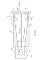
- FIG. 2 is a horizontal sectional view showing a part of the thermostatic apparatus according to Embodiment 1.
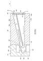
- FIG. 6 is a vertical sectional view schematically showing a gas sensor according to Embodiment 2.
- FIG. 3A is a vertical cross-sectional view schematically showing the thermostatic apparatus according to the second embodiment.
- FIG. 3B is a diagram schematically showing the flow of the gas in the tank.
- FIG. 4A is a vertical cross-sectional view schematically showing a gas sensor according to the first modification.
- FIG. 4B is a vertical sectional view schematically showing a gas sensor according to the second modification.
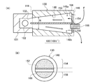
- FIG. 5A is a vertical cross-sectional view schematically showing a gas sensor according to the third embodiment.
- FIG. 5B is a diagram schematically showing an end face on the second end side of the gas sensor according to the third embodiment.
- FIG. 6A is a vertical cross-sectional view schematically showing a gas sensor according to the third modification.
- FIG. 6B is a diagram schematically illustrating an end surface on the second end side of the gas sensor according to the third modification.
- FIG. 6 is a vertical sectional view schematically showing a gas sensor according to a fourth embodiment.
- FIG. 8A is a vertical sectional view schematically showing a gas sensor according to the fifth embodiment.
- FIG. 8B is a horizontal sectional view schematically showing the gas sensor according to the fifth embodiment.
- FIG. 10 is a horizontal sectional view showing a gas sensor according to a sixth embodiment.
- FIG. 10 is a cross-sectional view schematically showing a part of a thermostatic apparatus according to Embodiment 7.
- FIG. 10 is a cross-sectional view showing the structure of a gas sensor according to a seventh embodiment.
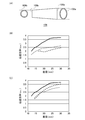
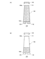
- FIG. 12A schematically shows the shapes of the first end and the second end.
- FIGS. 12B and 12C are graphs showing the relationship between the shape of the light path section and the light transmission efficiency from the light source to the detector. It is a schematic diagram for demonstrating arrangement
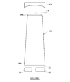
- FIG. 15A and FIG. 15B are schematic diagrams for explaining the material of the light path portion.
- FIG. 15A and FIG. 15B are schematic diagrams for explaining the material of the light path portion.
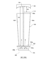
- FIG. 10 is a side view schematically showing a gas sensor according to an eighth embodiment.
- FIG. 10 is a side view schematically showing a gas sensor according to a ninth embodiment.
- FIG. 22 is a side view schematically showing a gas sensor according to the tenth embodiment.
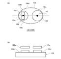
- FIG. 19A is a plan view schematically showing a gas sensor according to the eleventh embodiment.
- FIG. 19B is a side view schematically showing a detector and an optical filter provided in the gas sensor according to the eleventh embodiment.
- FIG. 20 is a side view schematically showing a gas sensor according to Embodiment 12.
- FIG. 1 is a horizontal sectional view showing a part of the thermostatic apparatus according to Embodiment 1.
- FIG. FIG. 1 illustrates a cross-sectional shape when the gas sensor 100 is observed from above in the vertical direction.
- the thermostatic device 1 according to the present embodiment includes a casing 2, a thermostatic bath 4, and a gas sensor 100 (100G).
- the thermostatic device 1 of the present embodiment is a CO 2 incubator with a dry heat sterilization function as an example.
- the housing 2 constitutes the outer housing of the thermostatic device 1.
- the constant temperature bath 4 is disposed inside the housing 2.
- the thermostat 4 contains a culture such as cells.
- the thermostat 1 can carry the culture into or out of the thermostat 4 via an outer door (not shown) provided in the housing 2 and an inner door (not shown) provided in the thermostat 4.
- the thermostat 4 contains a gas containing carbon dioxide (CO 2 ) or the like (hereinafter referred to as “in-vessel gas”).
- the gas sensor 100 is a sensor for detecting a predetermined gas (hereinafter referred to as a gas to be detected) contained in the in-vessel gas of the thermostatic chamber 4.
- the gas to be detected in the present embodiment is CO 2 as an example.
- the gas sensor 100 can detect the presence and concentration of the gas to be detected.
- the gas sensor 100 transmits a signal indicating the detection result to a control unit (not shown) of the thermostatic device 1.
- the gas sensor 100 is inserted into and fixed to the through hole 4 a that communicates the inside and outside of the thermostatic chamber 4.
- a heat insulating material (not shown) is disposed in the space between the housing 2 and the thermostatic chamber 4.
- the gas sensor 100 includes a gas detection unit 101 and a gas passage unit 130.
- the gas detection unit 101 includes a light source 102, a detector 104, a gas introduction chamber 132, and a bracket 134.
- the light source 102, the detector 104, the gas introduction chamber 132, and the bracket 134 are accommodated in the housing 101a.
- the light source 102 emits light having a predetermined wavelength.
- the light source 102 of the present embodiment is a thermal infrared light source made of a black body thin film as an example, and emits infrared light in a wide wavelength range.
- a thermal infrared light source that generates infrared light from a high-temperature heating element is mainly used.
- the heating element include a filament, a ceramic, and a thin film.
- an LED can be used as the light source 102.
- the light source 102 is mounted on the substrate 136 and is electrically connected to a wiring pattern (not shown) on the substrate 136.
- the detector 104 receives light from the light source 102 and detects the gas to be detected based on absorption of light by the gas to be detected. Specifically, the detector 104 receives light emitted from the light source 102 by a light receiving element (not shown) and detects the gas to be detected based on a change in light intensity caused by absorption of light by the gas to be detected. As an example, the detector 104 of the present embodiment is an infrared sensor that absorbs infrared light and outputs an electrical signal.
- an infrared sensor As such an infrared sensor, a change in temperature due to absorption of infrared light, such as a quantum sensor that outputs a signal by photoelectric conversion, such as a photodiode or a photoconductor, a thermopile, or a pyroelectric sensor, is converted into an electrical signal.
- a thermal type sensor etc. can be illustrated.
- the detector 104 is mounted on the substrate 138 and is electrically connected to a wiring pattern (not shown) on the substrate 138.
- the light source 102 and the detector 104 are arranged so that the light emitting surface 102a of the light source 102 and the light receiving surface 104e of the detector 104 face each other.
- a gas introduction chamber 132 into which the gas to be detected flows is arranged between the light source 102 and the detector 104.
- the gas introduction chamber 132 has a first space 132a, a second space 132b, and a third space 132c.
- the first space 132 a extends in a direction intersecting with the direction in which the light source 102 and the detector 104 are arranged, and is connected to the gas passage portion 130.
- the second space 132b extends from the first space 132a to the light source 102 side.
- the third space 132c extends from the first space 132a to the detector 104 side.
- the gas in the thermostatic chamber 4 flows through the gas passage portion 130.
- the gas in the tank that has passed through the first space 132a flows into the second space 132b and the third space 132c.
- the second space 132b between the first space 132a and the light source 102 and providing the third space 132c between the first space 132a and the detector 104 from the thermostat 4 to the light source 102 and the detector 104.
- the length of the flow path of the gas in the tank can be extended. Thereby, since the temperature of the gas in a tank which approaches the light source 102 and the detector 104 falls, the temperature rise of the light source 102 and the detector 104 can be suppressed.
- the light source 102 and the detector 104 are connected to the first space 132a without passing through the second space 132b and the third space 132c, it is necessary to increase the width of the first space 132a to the optical distance. In this case, it may be difficult to ensure the strength of the members that define the gas introduction chamber 132.
- the width of the first space 132a can be made shorter than the optical distance. Thereby, the strength of the member that defines the gas introduction chamber 132 can be more reliably ensured.
- a metal film is formed on the wall surface that defines the second space 132b and the wall surface that defines the third space 132c.
- the metal film is made of, for example, gold, aluminum, chromium or the like having a high reflectance in the infrared region.
- the light source 102 and the detector 104 are supported by a bracket 134.
- the bracket 134 has a first housing part 134a and a second housing part 134b.
- the first housing part 134 a is disposed adjacent to the second space 132 b of the gas introduction chamber 132.
- the light source 102 is accommodated in the first accommodating portion 134a.
- the light source 102 is disposed so that the light exit surface 102a faces the second space 132b.
- the first accommodating portion 134a has an opening on the second space 132b side. This opening is closed by the first lid member 140. Therefore, the gas introduction chamber 132 and the first housing part 134a are separated by the first lid member 140, and leakage of the gas in the tank into the first housing part 134a is suppressed. Thereby, it can suppress that the detection accuracy of the gas sensor 100 falls.
- the opening of the first housing part 134 a is hermetically sealed by the first lid member 140.
- the second storage part 134b is disposed adjacent to the third space 132c of the gas introduction chamber 132.
- the detector 104 is accommodated in the second accommodating portion 134b.
- the detector 104 is arranged so that the light receiving surface 104e faces the third space 132c side.
- the second housing part 134b has an opening on the third space 132c side. This opening is closed by the second lid member 142. Therefore, the gas introduction chamber 132 and the second accommodating portion 134b are separated by the second lid member 142, and leakage of the gas in the tank into the second accommodating portion 134b is suppressed. Thereby, it can suppress that the detection accuracy of the gas sensor 100 falls.
- the opening of the second housing part 134 b is hermetically sealed by the second lid member 142.
- the first lid member 140 and the second lid member 142 are made of a material that is transmissive to the light from the light source 102 (that is, has a low absorption rate of emitted light). Accordingly, the first lid member 140 and the second lid member 142 constitute an optical window. In the present embodiment, since infrared light is emitted from the light source 102, the first lid member 140 and the second lid member 142 are made of, for example, germanium, silicon, sapphire, or the like.
- the light source 102, the first lid member 140, and the second lid member 142 are connected via a bracket 134 so as to be able to conduct heat.
- the first lid member 140 and the second lid member 142 can be heated by the heat of the light source 102.
- the bracket 134 is formed of a material having high thermal conductivity such as aluminum.
- the detector 104 and the second lid member 142 are spaced apart. By providing a space between the detector 104 and the second lid member 142, heat conduction from the second lid member 142 to the detector 104 can be suppressed. Thereby, the detection accuracy of the gas sensor 100 can be further improved.
- the light source 102 and the first lid member 140 are arranged to contact each other. Thereby, the heat of the light source 102 can be efficiently transmitted to the first lid member 140. In addition, the light guide efficiency from the light source 102 to the detector 104 can be increased.
- the detector 104 is arranged so as to be separated from the wall surface of the second housing portion 134b. Thereby, it is possible to suppress the heat of the light source 102 from being transmitted to the detector 104 via the bracket 134.
- the light source 102 and the detector 104 are in communication with the outside of the gas sensor 100 and, consequently, the outside of the thermostat 1.
- the first housing portion 134a has an opening on the side opposite to the second space 132b.
- the second housing portion 134b has an opening on the side opposite to the third space 132c.
- the first storage part 134 a and the second storage part 134 b are formed of through holes provided in the bracket 134.
- the housing 101a is provided with an opening (not shown).
- the light source 102 and the detector 104 communicate with the outside of the gas sensor 100 and the outside of the thermostatic device 1. With such a configuration, the existence area of the light source 102 and the detector 104 can be ventilated with the outside.
- the gas detection unit 101 may include a heater (not shown) that heats the gas introduction chamber 132.
- the detection accuracy of the gas sensor 100 can be improved by keeping the temperature of the detection gas measurement area, in other words, the temperature of the detection gas existing space between the light source 102 and the detector 104 constant by the heater. Moreover, it can suppress that dew condensation arises in the 1st cover member 140 and the 2nd cover member 142. FIG.
- the gas passage portion 130 is a passage for the gas in the tank containing the gas to be detected, and is interposed between the thermostat 4 and the gas detection portion 101.
- the gas detection part 101 can be separated from the thermostat 4. Thereby, the transfer of heat from the internal space of the thermostat 4 to the light source 102 and the detector 104 can be suppressed.
- a decrease in detection accuracy of the gas sensor 100 can be suppressed.
- the gas passage portion 130 is formed of a tubular member, and extends from the first end portion 144, the second end portion 146 opposite to the first end portion 144, and the first end portion 144 to the second end portion 146. And a hollow portion 148.
- the first end 144 is disposed on the gas detection unit 101 side.
- the second end 146 is disposed on the gas space side where the detection target gas exists, that is, on the thermostatic chamber 4 side.
- the end of the hollow portion 148 on the first end 144 side is connected to the first space 132 a of the gas introduction chamber 132.
- the end of the hollow portion 148 on the second end 146 side is connected to the internal space of the thermostatic chamber 4.
- a cap 150 is fitted into the end portion of the hollow portion 148 on the second end portion 146 side.
- the cap 150 is made of a heat-resistant and water-repellent porous material, for example, a resin material such as polytetrafluoroethylene (PTFE), a metal mesh, a punching metal, an expanded metal, or the like.
- the heat resistance of the cap 150 is preferably 200 ° C. or higher.
- the cap 150 can pass the gas in the tank.
- the gas in the tank containing the gas to be detected flows between the thermostat 4 and the gas detection part 101 through the hollow part 148.
- the hollow portion 148 has at least part of a shape in which the flow path cross-sectional area N decreases stepwise or continuously as it approaches the first end portion 144 side from the second end portion 146 side. That is, the hollow portion 148 has a stepped area as the cross-sectional area perpendicular to the direction in which the first end portion 144 and the second end portion 146 are aligned approaches the first end portion 144 side from the second end portion 146 side. Alternatively, it has a continuously decreasing shape.
- the hollow portion 148 shown in FIG. 1 has a shape in which the flow path cross-sectional area N continuously decreases from the second end portion 146 to the first end portion 144.
- the gas in the tank can be easily taken into the hollow portion 148.
- the distance between the light source 102 and the detector 104 can be made closer.
- the distance between the light source 102 and the detector 104 in the present embodiment is, for example, about 10 mm.
- the gas passage portion 130 is at least partially made of a heat insulating material.
- the gas passage portion 130 of the present embodiment is entirely made of a heat insulating material.
- the non-heat insulating material is discontinuous at any position between the first end 144 and the second end 146. It is preferable that a heat insulating material is disposed. Since at least a part of the gas passage portion 130 is made of a heat insulating material, the heat of the internal space of the thermostatic chamber 4 is suppressed from being transmitted to the light source 102 and the detector 104 via the gas passage portion 130. Can do.
- the heat insulating material when the temperature inside the thermostat 4 is 190 ° C., a material in which the temperature around the light source 102 and the detector 104 is 100 ° C. or less is selected. By selecting a material having high thermal resistance as the heat insulating material, the heat insulating effect can be enhanced. Further, as the heat insulating material, a high temperature resistant resin is suitable. This is because the high-temperature resistant resin is easier to process than metal and has high thermal resistance.
- the heat insulating material examples include polyphenylene sulfide (PPS); fluorine resin such as polytetrafluoroethylene (PTFE) and Teflon (registered trademark); polyetheretherketone (PEEK); silicon resin; polyamideimide (PAI) and the like Can be illustrated.
- PPS polyphenylene sulfide
- fluorine resin such as polytetrafluoroethylene (PTFE) and Teflon (registered trademark)
- PEEK polyetheretherketone
- silicon resin silicon resin
- PAI polyamideimide
- the gas passage part 130 and the gas introduction chamber 132 of the gas detection part 101 are integrally formed of a heat insulating material. That is, the hollow portion 148, the first space 132a, the second space 132b, and the third space 132c are defined inside an integral tubular member made of a heat insulating material.
- the gas sensor 100 has a constant temperature bath in which the packing 120 is fitted between the outer side surface of the gas passage portion 130 and the inner side surface of the through hole 4a in a state where the gas passage portion 130 is inserted into the through hole 4a of the constant temperature bath 4. 4 is fixed.
- the packing 120 is made of, for example, a silicone resin.
- the second end 146 of the gas passage portion 130 is exposed in the constant temperature bath 4, the gas passage portion 130 is located in the through hole 4 a, and the gas detection portion 101 is located outside the constant temperature bath 4.
- the gas sensor 100 is arranged so that the gas passage portion 130 extends horizontally in a state of being fixed to the thermostatic chamber 4. That is, the gas sensor 100 is arranged such that the first end 144 and the second end 146 are aligned in the horizontal direction. As described above, by placing the gas sensor 100 horizontally, it is possible to suppress dust and liquid from entering the gas passage portion 130 and the gas introduction chamber 132 and to prevent the dust and liquid that have entered from collecting inside. Can do. Thereby, the fall of the detection accuracy of the gas sensor 100 can be suppressed.
- the hollow portion 148 and the first space 132 a extend in the horizontal direction and in the normal direction of the wall surface 4 b of the thermostat 4.
- the second space 132b and the third space 132c extend in the horizontal direction and parallel to the wall surface 4b of the thermostatic chamber 4.
- the light source 102 and the detector 104 are arranged in the horizontal direction.
- the hollow portion 148 has a substantially truncated cone-shaped portion whose bottom surface is located on the second end portion 146 side and whose top surface is located on the first end portion 144 side. Therefore, the surface of the hollow portion 148 on the lower side in the vertical direction is tapered at least partially so as to be inclined downward in the vertical direction as it approaches the second end portion 146 from the first end portion 144. Thereby, dust and liquid are easily discharged from the inside of the hollow portion 148 and the gas introduction chamber 132, so that accumulation of dust and liquid can be further suppressed.
- the gas in the thermostatic chamber 4 flows into the hollow portion 148 through the cap 150.
- the in-tank gas that has flowed into the hollow portion 148 advances toward the first end portion 144 and flows into the first space 132 a of the gas introduction chamber 132.
- the in-tank gas that has flowed into the first space 132a flows into the second space 132b and the third space 132c.
- the first space 132a to the third space 132c are filled with the gas in the tank.
- the light from the light source 102 is emitted toward the gas to be detected. That is, the light from the light source 102 is emitted toward the second space 132b that is filled with the in-tank gas containing the gas to be detected.
- the light emitted from the light source 102 includes the first lid member 140, the second space 132b, a region between the second space 132b and the third space 132c in the first space 132a, the third space 132c, and the second lid member 142.
- the detector 104 is reached. In this process, light of a predetermined wavelength is absorbed by the detection gas existing in the first space 132a to the third space 132c.
- the detector 104 can detect the presence and concentration of the gas to be detected from the change in the amount of light of the predetermined wavelength.
- infrared light is emitted from the light source 102, and light having a wavelength of 4.26 ⁇ m is absorbed by CO 2 present in the first space 132a to the third space 132c.
- the detector 104 uses the intensity (light quantity) of the light having a wavelength of 4.26 ⁇ m in the light emitted from the light source 102 as a reference, based on the intensity (light quantity) of the light having a wavelength of 4.26 ⁇ m in the light received by the light receiving element.
- the presence and concentration of 2 can be detected.
- the concentration of CO 2 that can be detected by the gas sensor 100 is, for example, 0 to 20%.
- the inventors measured the concentration of CO 2 using the gas sensor 100 according to the present embodiment.
- the distance from the first end 144 to the second end 146 was 50 mm.
- the distance from the first end 144 to the center of the light exit surface 102a in the direction in which the gas passage portion 130 and the gas detection portion 101 are arranged is 10 mm.
- the distance from the first lid member 140 to the second lid member 142 was 10 mm.
- the diameter of the hollow portion 148 on the second end 146 side was 20 mm.
- a 5% concentration CO 2 gas was introduced into the gas introduction chamber 132.
- As the light source 102 an infrared light source of black body radiation having a broad emission spectrum was used.
- An optical filter that transmits only light having a wavelength of 4.26 ⁇ m was installed on the light receiving surface 104 e of the detector 104.
- the CO 2 concentration result of the measurement the detection sensitivity of the gas sensor 100 is good, it was confirmed that can detect the concentration of CO 2 with high accuracy.
- the inside of the thermostat 4 was heated to 190 ° C., and the ambient temperature of the light source 102 and the detector 104 was measured. And it confirmed that the said ambient temperature was 100 degrees C or less.
- the gas sensor 100 includes the gas detection unit 101 having the light source 102 and the detector 104, and the gas passage through which the gas to be detected flows between the thermostat 4 and the gas detection unit 101.
- the gas passage part 130 has a first end part 144, a second end part 146, and a hollow part 148 extending from the first end part 144 to the second end part 146.
- the hollow portion 148 has a shape in which the flow path cross-sectional area N decreases stepwise or continuously as it approaches the first end portion 144 side from the second end portion 146 side.
- the first end 144 is disposed on the gas detection unit 101 side, and the second end 146 is disposed on the gas space side.
- the gas to be detected flows between the thermostat 4 and the gas detection unit 101 via the hollow portion 148.
- the gas passage part 130 By providing the gas passage part 130, the light source 102, the detector 104, and the thermostat 4 can be thermally separated. Thereby, when the temperature of the gas in the tank exceeds the heat resistance temperature of the light source 102 and the detector 104, or when dry heat sterilization is performed in the space filled with the gas in the tank, the temperature of the thermostatic chamber 4 is increased. Even in such a case, damage to the light source 102 and the detector 104 due to heat can be suppressed. Therefore, a decrease in detection accuracy of the gas sensor 100 can be suppressed.
- the concentration of the gas to be detected contained in the tank gas can be detected with high accuracy by mounting the gas sensor 100 on the thermostat 1, the performance of the thermostat 1 can be improved. Moreover, since the dry heat sterilization process can be performed without removing the gas sensor 100, the usability of the thermostatic device 1 can be improved.
- the light source 102 and the detector 104 are arranged in the horizontal direction, but the present invention is not particularly limited to this configuration.
- the light source 102 and the detector 104 may be arranged in the vertical direction. In this case, it is preferable to arrange the light source 102 below. Thereby, the heat of the light source 102 can be easily transmitted to the first lid member 140 and the second lid member 142. As a result, it is possible to suppress the occurrence of condensation on the first lid member 140.
- FIG. 2 is a vertical sectional view schematically showing a gas sensor according to the second embodiment.
- FIG. 3A is a vertical cross-sectional view schematically showing the thermostatic apparatus according to the second embodiment.
- FIG. 3B is a diagram schematically showing the flow of the gas in the tank.
- the gas sensor according to the present embodiment will be described mainly with respect to the configuration different from the first embodiment, and the common configuration will be briefly described or the description thereof will be omitted.
- the gas sensor 100 (100H) according to the present embodiment includes a gas detection unit 101 having a light source 102, a detector 104 (see FIG. 1) and a gas introduction chamber 132, and a gas passage unit 130.
- the gas passage portion 130 includes a first end portion 144, a second end portion 146, a hollow portion 148, and a partition member 152.
- the first end 144 is disposed on the gas detection unit 101 side, and the second end 146 is disposed on the constant temperature bath 4 side.
- the gas passage part 130 circulates the gas to be detected between the thermostat 4 and the gas detection part 101 through the hollow part 148.
- the hollow portion 148 has a shape in which the flow path cross-sectional area N decreases as it approaches the first end portion 144 side from the second end portion 146 side. Further, the hollow portion 148 is inclined so as to be directed downward in the vertical direction as the surface 148c on the lower side in the vertical direction approaches the second end portion 146 from the first end portion 144.
- the partition member 152 is a member that divides the hollow portion 148 into at least two regions, a first region 148a and a second region 148b.
- the hollow portion 148 is partitioned by the partition member 152 into two regions, a first region 148a and a second region 148b.
- the first region 148a and the second region 148b each extend from the first end 144 side to the second end 146 side.
- the partition member 152 extends from the first end 144 to the second end 146. Accordingly, the first region 148a and the second region 148b extend from the first end 144 to the second end 146, respectively.
- the gas passage part 130 has a gas inlet 154 and a gas outlet 156.
- the gas inlet 154 is disposed at the second end 146 and connects the internal space of the thermostat 4 and the first region 148a.
- the gas outlet 156 is disposed at the second end 146 and connects the second region 148 b and the internal space of the thermostatic chamber 4.
- the gas inlet 154 is blocked with a porous member 158, and the gas outlet 156 is blocked with a porous member 160.
- Examples of the material constituting the porous members 158 and 160 are the same as the material constituting the cap 150.
- the porous members 158 and 160 can pass the gas to be detected.
- the opening surfaces of the gas inlet 154 and the gas outlet 156 extend in parallel to the direction B (the direction indicated by the arrow B in FIG. 2) in which the first end 144 and the second end 146 are arranged. Since the porous member 158 and the porous member 160 extend parallel to the direction B, the opening surfaces of the gas inlet 154 and the gas outlet 156 extend parallel to the arrow B. Can understand. That is, the gas inlet 154 and the gas outlet 156 are disposed on the side surface of the gas passage portion 130.
- the gas sensor 100 has a gas inlet 154 and a gas outlet 156 that protrude from the wall surface 4b of the thermostatic chamber 4 into the internal space. Installed on the wall surface 4b. Normally, a gas flow (gas flow F) in the bath exists in the thermostat 4.
- the gas inlet 154 is arranged so that the opening surface intersects with the gas flow F in the thermostat 4, that is, intersects with the flow direction of the gas to be detected.
- the gas inlet 154 is arranged such that the opening surface is orthogonal to the gas flow F.
- the gas outlet 156 is disposed on the opposite side of the gas inlet 154 in the direction of the gas flow F.
- the gas inlet 154 is disposed on the upstream side of the gas flow F, and the gas outlet 156 is disposed on the downstream side of the gas flow F with respect to the gas inlet 154. Further, the second end 146 is arranged in a region where the detection target gas flows in the constant temperature chamber 4 downward in the vertical direction. The gas inlet 154 is disposed above the gas outlet 156 in the vertical direction.
- the in-tank gas including the detection gas existing in the thermostat 4 flows into the hollow portion 148 from the gas inlet 154, flows through the first region 148 a toward the first end 144, and enters the gas detection unit 101. To reach. Accordingly, the gas in the tank including the detection target gas existing in the gas detection unit 101 flows through the second region 148 b toward the second end 146 and flows out from the gas outlet 156 to the thermostatic chamber 4.
- the partition member 152 divides the hollow portion 148 into the first region 148a and the second region 148b, the gas inlet 154 is provided in the first region 148a, and the gas outlet 156 is provided in the second region 148b.
- the flow of the gas in the tank in the hollow portion 148 can be adjusted to generate convection.
- the gas to be detected can be introduced into the gas detection unit 101 more efficiently, and therefore the gas in the gas introduction chamber 132 can be replaced quickly. Therefore, the detection speed of the gas sensor 100 can be improved.
- the pressure applied to the upstream surface of the gas flow F that is, the surface where the gas flow F directly hits, That is, it becomes larger than the pressure applied to the surface where the gas flow F wraps around. Therefore, a pressure difference is generated between the upstream surface and the downstream surface. Therefore, by arranging the gas inlet 154 on the upstream side with respect to the gas flow F and arranging the gas outlet 156 on the downstream side, the gas in the tank is brought into the hollow portion 148 by utilizing this pressure difference. It can be introduced smoothly.
- the gas inlet 154 has an opening surface extending in parallel with the direction B in which the first end portion 144 and the second end portion 146 are arranged so that the opening surface intersects the direction of the gas flow F. Be placed. Thereby, since the gas flow F can be directly applied to the gas inflow port 154, the introduction efficiency of the gas to be detected to the gas detection unit 101 can be further increased.
- the second end 146 is arranged in a region where the gas in the tank flows downward in the vertical direction, and the gas inlet 154 is arranged vertically above the gas outlet 156.
- the above-mentioned pressure difference can be enlarged more using the gravity concerning a gas in a tank. Therefore, the introduction efficiency of the gas to be detected into the gas detection unit 101 can be further increased.
- the opening area of the gas inlet 154 is larger than that of the gas outlet 156.
- a differential pressure due to the difference in opening area can be generated in the first region 148a and the second region 148b (Bernoulli's theorem).
- the pressure in the second region 148b is smaller than that in the first region 148a. Therefore, the flow rate of the gas in the tank in the second region 148b is faster than that in the first region 148a. Therefore, the introduction efficiency of the gas to be detected into the gas detection unit 101 can be further increased.
- the thermostatic device 1 further includes a fan 6 that blows air so that the gas in the tank flows along the wall surface 4b.
- the gas sensor 100 is disposed on the downstream side of the gas flow F with respect to the fan 6.
- the thermostat 1 further includes a gas flow path 8 through which the gas in the tank flows.
- the gas flow path 8 is arranged along the wall surface 4 b in the internal space of the thermostatic chamber 4.
- the gas flow path 8 is defined by a partition plate 10 extending along the wall surface 4b and the wall surface 4b.
- the gas flow F can be reliably applied by the second end 146 of the gas sensor 100. Therefore, the introduction efficiency of the gas to be detected into the gas detection unit 101 can be further increased.
- the fan 6 is disposed in the vicinity of the inlet of the gas flow path 8.
- the thermostatic device 1 has a gas introduction pipe 12 for introducing the gas in the tank into the thermostatic tank 4.
- the gas introduction pipe 12 is preferably arranged so that the fan 6 is positioned between the gas introduction pipe 12 and the gas sensor 100.
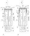
- FIG. 4A is a vertical cross-sectional view schematically showing a gas sensor according to the first modification.
- FIG. 4B is a vertical sectional view schematically showing a gas sensor according to the second modification.
- the opening surfaces of the gas inlet 154 and the gas outlet 156 have the first end 144 and the second end 146, respectively. It extends in a direction that intersects with the direction B of the line. Therefore, the gas inlet port 154 and the gas outlet port 156 have opening surfaces that extend substantially parallel to the gas flow F in the thermostat 4.
- the gas inlet 154 and the gas outlet 156 are closed with a porous member 162 through which the gas to be detected can pass. Examples of the material constituting the porous member 162 include the same materials as those constituting the cap 150. Even with such a configuration, the gas in the tank can be introduced into the hollow portion 148 using the pressure difference between the gas inlet 154 side and the gas outlet 156 side.
- the gas sensor 100 (100H ′′) according to the second modification has a structure in which the second embodiment and the first modification are combined.
- the opening surfaces of the gas inlets 154 and 156 include a region extending in parallel with the direction B in which the first end 144 and the second end 146 are aligned, and the first end 144 and the second end. 146 and a region extending in a direction intersecting with the direction B in which the 146 is arranged.
- FIG. 5A is a vertical cross-sectional view schematically showing a gas sensor according to the third embodiment.
- FIG. 5B is a diagram schematically showing an end face on the second end side of the gas sensor according to the third embodiment.
- the gas sensor according to the present embodiment will be described mainly with respect to the configuration different from the first embodiment, and the common configuration will be briefly described or the description thereof will be omitted.
- the gas sensor 100 (100I) according to the present embodiment includes a gas detection unit 101 having a light source 102, a detector 104 (see FIG. 1) and a gas introduction chamber 132, and a gas passage unit 130.
- the gas passage portion 130 includes a first end portion 144, a second end portion 146, a hollow portion 148, and a partition member 152.
- the first end 144 is disposed on the gas detection unit 101 side, and the second end 146 is disposed on the constant temperature bath 4 side.
- the gas passage part 130 circulates the gas to be detected between the thermostat 4 and the gas detection part 101 through the hollow part 148.
- the hollow portion 148 has a shape in which the flow path cross-sectional area N decreases as it approaches the first end portion 144 side from the second end portion 146 side. Further, the hollow portion 148 is inclined so as to be directed downward in the vertical direction as the surface 148c on the lower side in the vertical direction approaches the second end portion 146 from the first end portion 144.
- the partition member 152 is a member that divides the hollow portion 148 into at least two regions, a first region 148a and a second region 148b.
- the hollow portion 148 is partitioned by the partition member 152 into two regions, a first region 148a and a second region 148b.
- the first region 148a and the second region 148b extend from the first end 144 to the second end 146, respectively.
- the gas passage part 130 has a gas inlet 154 and a gas outlet 156.
- the gas inlet 154 is disposed at the second end 146 and connects the internal space of the thermostat 4 and the first region 148a.
- the gas outlet 156 is disposed at the second end 146 and connects the second region 148 b and the internal space of the thermostatic chamber 4.
- the gas inlet 154 and the gas outlet 156 are closed with a porous member 164 through which the gas to be detected can pass. Examples of the material constituting the porous member 164 include the same materials as those constituting the cap 150.
- the opening surfaces of the gas inlet 154 and the gas outlet 156 extend in a direction intersecting with the direction B in which the first end 144 and the second end 146 are arranged.
- the opening area of the gas inlet 154 is larger than that of the gas outlet 156.
- the end 152 a on the second end 146 side of the partition member 152 is embedded in the porous member 164.
- the end 152a constitutes a boundary between the gas inlet 154 and the gas outlet 156.
- the partition member 152 is inclined so as to be directed downward in the vertical direction as it approaches the second end 146 from the first end 144. Thereby, the gas inflow port 154 with a large opening area and the gas outflow port 156 with a small opening area are formed.
- the gas sensor 100 is installed on the wall surface 4b of the thermostatic chamber 4 (see FIGS. 1 and 3 (A)). Normally, a gas flow (gas flow F) in the bath exists in the thermostat 4.
- the gas inlet 154 is disposed on the upstream side of the gas flow F, and the gas outlet 156 is disposed on the downstream side of the gas flow F with respect to the gas inlet 154.
- the second end 146 is arranged in a region where the detection target gas flows in the constant temperature chamber 4 downward in the vertical direction.
- the gas inlet 154 is disposed above the gas outlet 156 in the vertical direction.
- the in-tank gas including the detection gas existing in the thermostat 4 flows into the hollow portion 148 from the gas inlet 154, flows through the first region 148 a toward the first end 144, and enters the gas detection unit 101. To reach. Accordingly, the gas in the tank including the detection target gas existing in the gas detection unit 101 flows through the second region 148 b toward the second end 146 and flows out from the gas outlet 156 to the thermostatic chamber 4.
- the partition member 152 divides the hollow portion 148 into the first region 148a and the second region 148b, the gas inlet 154 is provided in the first region 148a, and the gas outlet 156 is provided in the second region 148b.
- the flow of the gas in the tank in the hollow portion 148 can be adjusted. Thereby, the detection speed of the gas sensor 100 can be improved.
- the opening area of the gas inlet 154 is larger than that of the gas outlet 156. For this reason, a differential pressure due to a difference in opening area is generated in the first region 148a and the second region 148b. Specifically, the pressure in the second region 148b is smaller than that in the first region 148a. Thereby, compared with the 1st area
- the channel cross-sectional area of the second region 148b is smaller than the channel cross-sectional area of the first region 148a at least partially.
- the second end 146 is disposed in a region where the gas in the tank flows downward in the vertical direction, and the gas inlet 154 is disposed above the gas outlet 156 in the vertical direction.
- the pressure difference in the gas inflow port 154 and the gas outflow port 156 can be enlarged using the gravity concerning a gas in a tank. Therefore, the introduction efficiency of the gas to be detected into the gas detection unit 101 can be further increased.
- FIG. 6A is a vertical cross-sectional view schematically showing a gas sensor according to the third modification.
- FIG. 6B is a diagram schematically illustrating an end surface on the second end side of the gas sensor according to the third modification.
- the gas inlet 154 and the gas flow are blocked by partially blocking the gas outlet 156.
- a difference is made in the opening area of the outlet 156.
- a rectifying plate 166 having a fin structure is used as a member that closes a part of the gas outlet 156.
- the rectifying plate 166 is a member that protrudes from the region between the gas inlet 154 and the gas outlet 156 at the second end 146 toward the internal space of the thermostatic chamber 4.
- the rectifying plate 166 is embedded in a region of the porous member 164 in contact with the second region 148b at the end on the gas passage portion 130 side. Thereby, the opening area of the gas outlet 156 can be made smaller than the opening area of the gas inlet 154.
- the rectifying plate 166 regulates the gas flow F (detected gas flow) in the thermostatic chamber 4 by a portion protruding toward the internal space of the thermostatic chamber 4. A part of the gas in the tank flowing through the thermostat 4 hits the current plate 166 when passing in the vicinity of the second end 146, and the traveling direction is directed to the gas inlet 154. Therefore, the gas in the tank can be guided into the hollow portion 148 by the rectifying plate 166. Thereby, the introduction efficiency of the gas to be detected into the gas detection unit 101 can be further increased.
- FIG. 7 is a vertical sectional view schematically showing a gas sensor according to the fourth embodiment.
- the gas sensor according to the present embodiment will be described mainly with respect to the configuration different from the first embodiment, and the common configuration will be briefly described or the description thereof will be omitted.
- the gas sensor 100 (100J) according to the present embodiment includes a gas detection unit 101 having a light source 102, a detector 104, and a gas introduction chamber 132, and a gas passage unit 130.
- the gas passage portion 130 includes a first end portion 144, a second end portion 146, a hollow portion 148, and a partition member 152.
- the first end 144 is disposed on the gas detection unit 101 side
- the second end 146 is disposed on the constant temperature bath 4 side.
- the gas passage part 130 circulates the gas to be detected between the thermostat 4 and the gas detection part 101 through the hollow part 148.
- the hollow portion 148 has a shape in which the flow path cross-sectional area N decreases as it approaches the first end portion 144 side from the second end portion 146 side. Further, the hollow portion 148 is inclined so as to be directed downward in the vertical direction as the surface 148c on the lower side in the vertical direction approaches the second end portion 146 from the first end portion 144.
- the partition member 152 is a member that divides the hollow portion 148 into at least two regions, a first region 148a and a second region 148b.
- the hollow portion 148 is partitioned by the partition member 152 into two regions, a first region 148a and a second region 148b.
- the first region 148a and the second region 148b extend from the first end 144 to the second end 146, respectively.
- the gas passage part 130 has a gas inlet 154 and a gas outlet 156.
- the gas inlet 154 is disposed at the second end 146 and connects the internal space of the thermostat 4 and the first region 148a.
- the gas outlet 156 is disposed at the second end 146 and connects the second region 148 b and the internal space of the thermostatic chamber 4.
- the gas inlet 154 and the gas outlet 156 are closed with a porous member 168 through which the gas to be detected can pass. Examples of the material constituting the porous member 168 include the same materials as those constituting the cap 150.
- the opening surfaces of the gas inlet 154 and the gas outlet 156 extend in a direction intersecting with the direction B in which the first end 144 and the second end 146 are arranged. Further, the gas inlet 154 has a larger opening area than the gas outlet 156.
- the light source 102 is arranged below the detector 104 in the vertical direction. Further, the gas inlet 154 is disposed below the gas outlet 156 in the vertical direction. Therefore, the first region 148a extends vertically below the second region 148b.
- the gas in the gas introduction chamber 132 is warmed by the heat of the light source 102 disposed below in the vertical direction. As a result, a gas flow rising from the light source 102 toward the detector 104 is generated. The gas that has flowed upward in the gas introduction chamber 132 travels through the second region 148b toward the second end 146 and flows out from the gas outlet 156.
- the pressure is reduced by the upward flow of gas caused by the heat of the light source 102.
- the gas in the tank flows from the gas inlet 154 into the first region 148a.
- a circulation of the gas in the tank occurs in which the gas in the tank that has flowed into the hollow portion 148 from the gas inlet 154 reaches the gas detection unit 101 and flows out of the gas outlet 156 again through the hollow portion 148. .
- the partition member 152 divides the hollow portion 148 into the first region 148a and the second region 148b, the gas inlet 154 is provided in the first region 148a, and the gas outlet 156 is provided in the second region 148b.
- the flow of the gas in the tank in the hollow portion 148 can be adjusted.
- the detection speed of the gas sensor 100 can be improved.
- the gas to be detected is circulated using the heat of the light source 102, the detection speed of the gas sensor 100 can be further improved.
- the hollow portion 148 has a taper shape that is inclined so as to be directed upward in the vertical direction as the surface 148d on the upper side in the vertical direction approaches the second end portion 146 from the first end portion 144.
- the flow of the gas in the tank from the gas detection unit 101 to the gas outlet 156 can be made smoother. Therefore, the detection speed of the gas sensor 100 can be further improved.
- the inclination of the upper surface 148d in the vertical direction is steeper than the inclination of the lower surface 148c in the vertical direction. Thereby, the enlargement of the gas sensor 100 can be suppressed.
- the opening area of the gas inlet 154 is larger than that of the gas outlet 156. For this reason, a differential pressure due to a difference in opening area is generated in the first region 148a and the second region 148b. Thereby, compared with the 1st area
- the partition member 152 is inclined so as to be directed upward in the vertical direction as it approaches the second end 146 from the first end 144. For this reason, at least in part, the channel cross-sectional area of the second region 148b is smaller than the channel cross-sectional area of the first region 148a. Thereby, compared with the 1st area
- FIG. 8A is a vertical sectional view schematically showing a gas sensor according to the fifth embodiment.
- FIG. 8B is a horizontal sectional view schematically showing the gas sensor according to the fifth embodiment.
- the gas sensor according to the present embodiment will be described mainly with respect to the configuration different from the first and second embodiments, and the configuration common to the first or second embodiment will be described briefly or the description will be omitted.
- the gas sensor 100 (100K) according to the present embodiment includes a gas detection unit 101 having a light source 102 and a detector 104, and a gas passage unit 130.
- the gas passage portion 130 includes a first end portion 144, a second end portion 146, a hollow portion 148, and a partition member 152.
- the first end 144 is disposed on the gas detection unit 101 side
- the second end 146 is disposed on the constant temperature bath 4 side.
- the gas passage part 130 circulates the gas to be detected between the thermostat 4 and the gas detection part 101 through the hollow part 148.
- the hollow portion 148 has a shape in which the flow path cross-sectional area N decreases as it approaches the first end portion 144 side from the second end portion 146 side. Further, the hollow portion 148 is inclined so as to be directed downward in the vertical direction as the surface 148c on the lower side in the vertical direction approaches the second end portion 146 from the first end portion 144.
- the partition member 152 is a member that divides the hollow portion 148 into at least two regions, a first region 148a and a second region 148b.
- the hollow portion 148 is partitioned by the partition member 152 into two regions, a first region 148a and a second region 148b.
- the first region 148a and the second region 148b each extend from the first end 144 side to the second end 146 side. Note that both ends of the partition member 152 do not extend to the first end 144 and the second end 146. Therefore, in the hollow part 148, both ends of the first region 148a and the second region 148b communicate with each other.
- connection area between the first region 148a and the second region 148b on the first end 144 side and the connection area on the second end 146 side are the majority of the gas in the tank that has flowed from the gas inlet 154 Or all are set so that it may flow through the 1st field 148a to the 1st end 144 side.
- the gas passage part 130 has a gas inlet 154 and a gas outlet 156.
- the gas inlet 154 is disposed at the second end 146 and connects the thermostat 4 and the first region 148a.
- the gas outlet 156 is disposed at the second end 146 and connects the second region 148 b and the thermostatic chamber 4.
- the gas inlet 154 is blocked with a porous member 158, and the gas outlet 156 is blocked with a porous member 160.
- the opening surfaces of the gas inlet 154 and the gas outlet 156 extend in parallel to the direction B in which the first end 144 and the second end 146 are arranged. That is, the gas inlet 154 and the gas outlet 156 are disposed on the side surface of the gas passage portion 130.
- the light source 102 is arranged so that the light emitting surface 102a faces the hollow portion 148 side. That is, the light source 102 is disposed so that the emitted light M passes through the hollow portion 148.
- the detector 104 is arranged so that the light receiving surface 104e faces the hollow portion 148 side. The positional relationship between the light source 102 and the detector 104 is determined so that the light M emitted from the light source 102 is not directly irradiated onto the light receiving surface 104e of the detector 104.
- the gas sensor 100 includes a light reflection unit 108.
- the light reflecting portion 108 is fixed to the second end 146 of the gas passage portion 130.
- the light reflecting portion 108 includes a concave reflecting surface 108a.
- the concave reflecting surface 108a is disposed so as to face the hollow portion 148. Thereby, the concave reflecting surface 108 a faces the light source 102 and the detector 104.
- the concave reflecting surface 108a can be formed, for example, by depositing a metal such as gold, aluminum, or chromium having a high reflectance in the infrared region on the surface of the light reflecting portion 108.
- the light M emitted from the light source 102 travels through the hollow portion 148 and is reflected by the concave reflecting surface 108a, travels through the hollow portion 148 again, and reaches the detector 104. Accordingly, the hollow portion 148 also functions as a light M path.
- a metal film 114 is formed on the wall surface that defines the hollow portion 148.
- the metal film 114 is made of, for example, gold, aluminum, chromium or the like having a high reflectance in the infrared region.
- the partition member 152 is made of metal.
- the partition member 152 is made of gold, aluminum, chromium or the like having a high reflectance in the infrared region.
- the surface of the partition member 152 is subjected to a mirror surface treatment, and the reflectance of the light M is increased. Thereby, the light guide efficiency from the light source 102 to the detector 104 can be improved.
- the gas detection unit 101 has a bracket 170.
- the bracket 170 includes the light source 102 and the housing portion 172 for the detector 104.
- the accommodating part 172 has an opening on the hollow part 148 side. This opening is closed by the lid member 174.
- the opening of the accommodating portion 172 is hermetically sealed by the lid member 174.
- the lid member 174 is made of a material that is transmissive to the light from the light source 102. In the present embodiment, since infrared light is emitted from the light source 102, the lid member 174 is made of, for example, germanium, silicon, sapphire, or the like.
- the gas sensor 100 is installed on the wall surface 4b of the thermostat 4 so that the gas inlet 154 and the gas outlet 156 protrude from the wall 4b of the thermostat 4 into the bath (see FIG. 3A).
- the gas inlet 154 is arranged so that the opening surface intersects with the gas flow F in the thermostat 4 (that is, the direction in which the gas to be detected flows).
- the gas inlet 154 is arranged such that the opening surface is orthogonal to the gas flow F.
- the gas outlet 156 is disposed on the opposite side of the gas inlet 154 in the direction of the gas flow F.
- the gas inlet 154 is disposed on the upstream side of the gas flow F, and the gas outlet 156 is disposed on the downstream side of the gas flow F with respect to the gas inlet 154. Further, the second end 146 is arranged in a region where the detection target gas flows in the constant temperature chamber 4 downward in the vertical direction. The gas inlet 154 is disposed above the gas outlet 156 in the vertical direction.
- the in-tank gas existing in the thermostat 4 flows into the hollow portion 148 from the gas inlet 154, flows through the first region 148 a toward the first end 144, and reaches the gas detection unit 101. Accordingly, the gas in the tank existing in the gas detection unit 101 (the gas in the tank in contact with the lid member 174) flows through the second region 148b toward the second end 146 and enters the thermostatic chamber 4 from the gas outlet 156. leak.
- the partition member 152 divides the hollow portion 148 into the first region 148a and the second region 148b, the gas inlet 154 is provided in the first region 148a, and the gas outlet 156 is provided in the second region 148b.
- the flow of the gas in the tank in the hollow portion 148 can be adjusted. Thereby, the introduction efficiency of the to-be-detected gas to the gas detection part 101 can be raised, and the detection speed of the gas sensor 100 can be improved.
- a pressure difference can be generated between the upstream surface and the downstream surface of the gas flow F.
- the gas inlet 154 has an opening surface extending in parallel with the direction B in which the first end portion 144 and the second end portion 146 are arranged so that the opening surface intersects the direction of the gas flow F. Be placed. Thereby, the introduction efficiency of the gas to be detected into the gas detection unit 101 can be further increased. Further, the second end 146 is disposed in a region where the gas in the tank flows downward in the vertical direction, and the gas inlet 154 is disposed vertically above the gas outlet 156. Thereby, the introduction efficiency of the gas to be detected into the gas detection unit 101 can be further increased.
- the opening area of the gas inlet 154 is larger than that of the gas outlet 156. For this reason, a differential pressure resulting from a difference in opening area is generated in the first region 148a and the second region 148b. Thereby, the introduction efficiency of the gas to be detected into the gas detection unit 101 can be further increased.
- the light M emitted from the light source 102 travels through the hollow portion 148 and reaches the second end portion 106b directly or while being reflected by the metal film 114 and the partition member 152. Then, the light M is reflected by the concave reflecting surface 108 a, travels through the hollow portion 148 again, and reaches the detector 104 directly or while being reflected by the metal film 114 and the partition member 152. In this process, the light M passes through the tank gas filled in the hollow portion 148. At this time, light of a predetermined wavelength is absorbed by the detection gas contained in the tank gas.
- the detector 104 uses the intensity (light quantity) of light of a predetermined wavelength in the light emitted from the light source 102 as a reference, and the presence of the gas to be detected based on the intensity (light quantity) of light of the predetermined wavelength in the light received by the light receiving element. And the concentration can be detected.
- the measurement distance of the gas to be detected can be increased by adopting a configuration in which the light M is passed through the hollow portion 148 filled with the gas in the tank and the gas to be detected is detected.
- a gas that requires a relatively long measurement distance such as water vapor (H 2 O)
- water vapor H 2 O
- the opening shape on the first end portion 144 side is an elliptical shape
- the opening shape on the second end portion 146 side is a perfect circle.
- the hollow portion 148 has a shape that gradually changes from the ellipse to the perfect circle from the first end 144 to the second end 146.
- the transmission efficiency of the light M from the light source 102 to the detector 104 can be improved as compared with a hollow portion having a perfect circle shape or an elliptic shape at both ends.
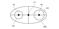
- the light source 102 and the detector 104 are located at the center of the ellipse (the length of the ellipse) when viewed from the arrangement direction of the light source 102, the detector 104, and the hollow portion 148. It is preferably arranged at a point-symmetrical position with the symmetry point (the intersection of the axis and the short axis). In this case, for example, arbitrary portions of the light source 102 and the detector 104 are arranged at point-symmetric positions. Alternatively, the center of the light emission surface 102a of the light source 102 and the center of the second detection unit 104b of the detector 104 are arranged at point-symmetric positions.
- the light source 102 and the detector 104 are more preferably arranged on the major axis of the ellipse, more preferably the light source 102 is arranged on one focus of the ellipse, and the detector 104 is arranged on the other focus of the ellipse. . Thereby, the transmission efficiency of the light M can be further improved.
- FIG. 9 is a horizontal sectional view showing a gas sensor according to the sixth embodiment.
- the gas sensor according to the present embodiment will be described mainly with respect to the configuration different from that of the first embodiment, and the configuration common to the first embodiment will be described briefly or the description thereof will be omitted.
- the gas sensor 100 (100L) according to the present embodiment includes a gas detection unit 101 having a light source 102, a detector 104, and a gas introduction chamber 132, and a gas passage unit 130.
- the gas passage portion 130 has a first end portion 144, a second end portion 146, and a hollow portion 148.
- the first end 144 is disposed on the gas detection unit 101 side
- the second end 146 is disposed on the constant temperature bath 4 side.
- the gas passage part 130 circulates the gas to be detected between the thermostat 4 and the gas detection part 101 through the hollow part 148.
- the hollow portion 148 has a shape in which the flow path cross-sectional area N decreases as it approaches the first end portion 144 side from the second end portion 146 side.
- the light source 102 is mounted on the substrate 136 and is electrically connected to a wiring pattern (not shown) on the substrate 136.
- a heating element 180 is mounted on the substrate 136.
- the heating element 180 is a resistor that generates heat up to a predetermined temperature when energized, for example.
- the heating element 180 is disposed in the vicinity of the first lid member 140 and is electrically connected to the wiring pattern on the substrate 136.
- the first lid member 140 and the second lid member 142 can be heated by the heat of the heating element 180.
- the detector 104 is mounted on the substrate 138 and is electrically connected to a wiring pattern (not shown) on the substrate 138.
- a heating element 182 is mounted on the substrate 138.
- the heating element 182 is formed of a resistor similar to the heating element 180.
- the heating element 182 is disposed in the vicinity of the second lid member 142 and is electrically connected to the wiring pattern on the substrate 138.
- the first lid member 140 and the second lid member 142 can be heated by the heat of the heating element 182.
- Heating the first lid member 140 and the second lid member 142 with the heating elements 180 and 182 can suppress the occurrence of condensation on the first lid member 140 and the second lid member 142. By suppressing the occurrence of condensation, it is possible to suppress a decrease in light guide efficiency from the light source 102 to the detector 104, and to further improve the detection accuracy of the gas sensor 100. Further, by using the heating elements 180 and 182, the gas sensor 100 can be reduced in size as compared with the case where a heater is provided. In addition, since the first lid member 140 and the second lid member 142 can be locally heated, the power consumption of the gas sensor 100 can be reduced. Further, by mounting the heating element 180 on the same substrate 136 as the light source 102 and mounting the heating element 182 on the same substrate 138 as the detector 104, the gas sensor 100 can be reduced in size and the number of components can be reduced.
- the detector 104 is a device whose output tends to fluctuate depending on the ambient temperature.
- a thermopile which is an example of the detector 104
- the detection element comprised of a thermopile has a pedestal and a thin film part thermally separated from the pedestal.
- the thin film part functions as a detection part whose temperature rises due to absorption of infrared rays.
- the detection element detects an electromotive force due to a temperature difference between the thin film portion and the pedestal using the pedestal as a cold junction, that is, a reference temperature. For this reason, the temperature change of the base and the wiring thermally connected to the base greatly affects the output of the detection element.
- a heat insulating material is disposed between the substrate and the detection element to suppress the heat of the substrate from being transmitted to the detection element.
- the substrate 138 is heated by the heating element 182. For this reason, there is a possibility that the output fluctuation of the detector 104 due to heat cannot be sufficiently suppressed only by the heat insulating material. On the other hand, as a result of intensive studies, the present inventors have found that the output fluctuation of the detector 104 can be suppressed by adjusting the balance of the heat generation amounts of the heating element 180 and the heating element 182.
- the signal intensity of the detector 104 tends to decrease with time. This is presumably because the temperature difference between the detection unit and the cold junction decreased as a result of the temperature on the cold junction side being increased by heating the substrate 138.
- the output of the detector 104 fluctuates due to a change in the ambient temperature, the change in the temperature difference between the cold junction and the detection unit is eliminated with time, so the output fluctuation is eliminated.
- heating by the heating element 182 is local. For this reason, even if time passes, the change of the temperature difference between the cold junction and the detection unit is difficult to be eliminated, and the output fluctuation tends to be maintained.
- the signal intensity of the detector 104 tends to increase with time. This is considered because the detection part of the detector 104 was heated by the radiant heat resulting from the temperature rise on the light source 102 side, and the temperature difference between the cold junction and the detection part increased.
- the output fluctuation of the detector 104 can be canceled out.
- the output fluctuation of the detector 104 can be suppressed by causing the heating element 180 and the heating element 182 to generate heat and making the amount of heat generated by the heating element 180 larger than the amount of heat generated by the heating element 182. Thereby, stable gas detection becomes possible.
- the amount of heat given to the detector 104 by the heating element 180 and the heating element 182 can also be adjusted by the arrangement of the heating elements 180 and 182, the heat insulation of the substrates 136 and 138, and the bracket 134.
- the heating element 180 is mounted on the substrate 136 and the heating element 182 is mounted on the substrate 138.
- the heating element is used.
- the configuration may be such that only one of 180 and heating element 182 is provided.
- FIG. 10 is a cross-sectional view schematically showing a part of the thermostatic apparatus according to the seventh embodiment.
- FIG. 11 is a cross-sectional view showing the structure of the gas sensor according to the seventh embodiment.
- the thermostatic device 1 according to the present embodiment includes a casing 2, a thermostatic bath 4, and a gas sensor 100 (100A).
- the thermostatic device 1 of the present embodiment is a CO 2 incubator with a dry heat sterilization function as an example.
- the housing 2 constitutes the outer housing of the thermostatic device 1.
- the constant temperature bath 4 is disposed inside the housing 2.
- the thermostat 4 contains a culture such as cells.
- the thermostat 1 can carry the culture into or out of the thermostat 4 via an outer door (not shown) provided in the housing 2 and an inner door (not shown) provided in the thermostat 4.
- the thermostat 4 contains a gas containing carbon dioxide (CO 2 ) or the like (hereinafter referred to as “in-vessel gas”).
- the gas sensor 100 is a sensor for detecting a gas in the thermostat 4 (hereinafter referred to as a gas to be detected).
- the gas to be detected in the present embodiment is CO 2 as an example.
- the gas sensor 100 can detect the presence and concentration of the gas to be detected.
- the gas sensor 100 transmits a signal indicating the detection result to a control unit (not shown) of the thermostatic device 1.
- the gas sensor 100 is inserted and fixed in the through hole 4a that communicates the inside and outside of the thermostatic chamber 4.
- a part of the gas sensor 100 is arranged inside the thermostat 4 and the remaining part is arranged in a space between the housing 2 and the thermostat 4.
- a heat insulating material (not shown) is arranged in the space between the housing 2 and the constant temperature bath 4.
- the gas sensor 100 includes a light source 102, a detector 104, a light passage unit 106, and a light reflection unit 108.
- the light source 102 emits light having a predetermined wavelength.
- the light source 102 of the present embodiment is a thermal infrared light source made of a black body thin film as an example, and emits infrared light in a wide wavelength range.
- a thermal infrared light source that generates infrared light from a high-temperature heating element is mainly used. Examples of the heating element include a filament, a ceramic, and a thin film. Further, an LED can be used as the light source 102.
- the detector 104 detects the gas to be detected based on light absorption by the gas to be detected. Specifically, the detector 104 receives light emitted from the light source 102 by a light receiving element (not shown) and detects the gas to be detected based on a change in light intensity caused by absorption of light by the gas to be detected. As an example, the detector 104 of the present embodiment is an infrared sensor that absorbs infrared light and outputs an electrical signal.
- an infrared sensor As such an infrared sensor, a change in temperature due to absorption of infrared light, such as a quantum sensor that outputs a signal by photoelectric conversion, such as a photodiode or a photoconductor, a thermopile, or a pyroelectric sensor, is converted into an electrical signal.
- a thermal type sensor etc. can be illustrated.
- the light source 102 and the detector 104 are mounted on the substrate 110.
- the light source 102 and the detector 104 are electrically connected to a wiring pattern (not shown) on the substrate 110.
- the positional relationship between the light source 102 and the detector 104 is determined so that the light emitted from the light source 102 is not directly applied to the light receiving surface of the detector 104.
- the light receiving surface of the detector 104 is arranged behind the light emitting surface of the light source 102 in the infrared light emission direction.
- the substrate 110 is supported by the substrate holder 112. Further, when a thermal type sensor such as a thermopile is used as the detector 104, the measurement accuracy of the detector 104 may be reduced by the heat of the light source 102 being transmitted to the detector 104. For this reason, it is preferable to provide a heat insulating material between the detector 104 and the light source 102.
- the light path portion 106 is a path for light emitted from the light source 102.
- the light path portion 106 of the present embodiment is configured by a tubular member having a first end portion 106a and a second end portion 106b opposite to the first end portion 106a.
- the substrate holder 112 is fixed to the first end portion 106a.
- the light source 102 and the detector 104 are arrange
- the light source 102 is arranged so that the emitted light passes through the hollow portion of the tubular member.
- a metal film 114 is formed on the inner surface of the tubular member.
- the metal film 114 is made of, for example, gold, aluminum, chromium or the like having a high reflectance in the infrared region. By providing the metal film 114, it is possible to suppress the light from the light source 102 from being absorbed by the light path unit 106, and to suppress a decrease in the amount of light received by the detector 104.
- the light passage portion 106 includes a light reflection portion holder 106c extending from the second end portion 106b in the direction opposite to the first end portion 106a.
- the light reflecting portion holder 106c is tubular, and the light reflecting portion 108 is fitted inside the light reflecting portion holder 106c. Further, the cap 116 is put on the light reflecting portion holder 106c.
- the cap 116 is made of a porous material having high heat resistance such as polytetrafluoroethylene (PTFE).
- the gas space GS is a space in which the gas in the tank containing the gas to be detected exists, and is therefore a measurement region for the gas to be detected.
- the light reflecting portion holder 106c has an opening 106d that communicates the outside of the gas sensor 100 and the inside of the light reflecting portion holder 106c at a position corresponding to the gas space GS. The gas in the tank can enter the gas space GS through the opening 106d.
- the light reflecting portion 108 is disposed on the second end portion 106b side of the light passage portion 106 with the gas space GS interposed therebetween.
- the light reflecting portion 108 includes a concave reflecting surface 108a.
- the concave reflecting surface 108 a is disposed so as to face the hollow portion of the light path portion 106. Thereby, the concave reflecting surface 108 a faces the light source 102 and the detector 104.
- the concave reflecting surface 108a can be formed, for example, by depositing a metal such as gold, aluminum, or chromium having a high reflectance in the infrared region on the surface of the light reflecting portion 108.
- a lid member 118 is provided at the second end portion 106b.
- the lid member 118 closes the opening on the second end portion 106 b side of the light path portion 106.
- the lid member 118 is made of a material that is transmissive to the light emitted from the light source 102 (that is, has a low absorption rate of the emitted light).
- the lid member 118 since infrared light is emitted from the light source 102, the lid member 118 is made of, for example, germanium, silicon, sapphire, or the like.
- the distance between the concave reflecting surface 108a and the lid member 118 is the distance (optical distance) at which the gas to be detected is measured by the light emitted from the light source 102.
- the gas sensor 100 has a constant temperature by inserting a packing 120 between the outer surface of the light passage portion 106 and the inner surface of the through hole 4a in a state where the light passage portion 106 is inserted into the through hole 4a of the constant temperature bath 4. Fixed to the tank 4.
- the packing 120 is made of, for example, a silicone resin.
- the opening 106 d of the light passage unit 106 is located inside the thermostat 4, and the light source 102 and the detector 104 are located outside the thermostat 4.
- the light emitted from the light source 102 reaches the light reflecting portion 108 through the light passage portion 106 and the gas space GS. Then, the light is reflected by the concave reflecting surface 108 a of the light reflecting portion 108 and reaches the detector 104 through the gas space GS and the light passage portion 106. More specifically, the light from the light source 102 enters the hollow portion of the light passage portion 106 from the first end portion 106 a and reaches the second end portion 106 b directly or while being reflected by the metal film 114. Then, the gas passes through the lid member 118 and enters the gas space GS.
- the light traveling in the gas space GS is reflected by the concave reflecting surface 108a, and enters the hollow portion of the light passage portion 106 again from the gas space GS through the lid member 118.
- the light incident on the hollow portion proceeds to the first end portion 106 a side while being reflected by the metal film 114, and reaches the detector 104.
- the light emitted from the light source 102 passes through the gas space GS in the process of reaching the detector 104 from the light source 102. At this time, light of a predetermined wavelength is absorbed by the detection gas existing in the gas space GS.
- infrared light is emitted from the light source 102, and light having a wavelength of 4.26 ⁇ m is absorbed by CO 2 present in the gas space GS.
- the detector 104 uses the intensity (light quantity) of the light having a wavelength of 4.26 ⁇ m in the light emitted from the light source 102 as a reference, based on the intensity (light quantity) of the light having a wavelength of 4.26 ⁇ m in the light received by the light receiving element.
- the presence and concentration of CO 2 in the space GS can be detected.
- the concentration of CO 2 that can be detected by the gas sensor 100 is, for example, 0 to 20%.
- the gas sensor 100 includes the light passage portion 106, the light source 102 and the detector 104 can be separated from the gas space GS. For this reason, exposure of the light source 102 and the detector 104 to the gas in the tank can be avoided. Further, heat transfer from the internal space of the thermostatic chamber 4 to the light source 102 and the detector 104 can be suppressed. Thereby, since the damage by the heat of the light source 102 and the detector 104 can be suppressed, the fall of the detection accuracy of the gas sensor 100 can be suppressed.
- the shape of the light path section 106, the arrangement of the light source 102, the detector 104, and the light reflection section 108, and the material of the light path section 106 will be described in more detail.
- FIG. 12A is a diagram schematically showing the shapes of the first end 106a and the second end 106b.
- FIGS. 12B and 12C are graphs showing the relationship between the shape of the light path portion 106 and the light transmission efficiency from the light source 102 to the detector 104.
- the first optical path portion in which the first end portion 106a is elliptical and the second end portion 106b is circular
- the first light path portion is a circular shape (both the first end portion 106a and the second end portion 106b) and the elliptical tube shape (therefore, the first end portion 106a and the second end portion 106b are both elliptical).
- a third light path portion was prepared.
- the relationship between the diameter and transmission efficiency at the time of changing the diameter of the perfect circle of the 2nd end part 106b was measured.
- the major axis and minor axis of the ellipse were fixed at 16 mm and 8 mm, respectively.
- the size of the ellipse is the minimum size including the light emitting surface of the light source 102 and the light receiving surface of the light receiving element included in the detector 104. Excluding the light transmission efficiency between the light source 102 and the light reflection unit 108 and between the light reflection unit 108 and the detector 104, only the transmission efficiency on the plane including the first end 106a was considered. In this case, the light transmission efficiency is improved as the area of the ellipse is smaller.
- the first end 106a is elliptical and the second end 106b is a perfect circle
- the fourth optical path portion having the first end portion 106a and the second end portion 106b are both circular, and the elliptical frustum shape (therefore, the first end portion 106a and the second end portion 106b are both elliptical.
- a fifth light path part is also included in the measurement of the transmission efficiency whose result is shown in FIG. 12C.
- the relationship between the diameter and transmission efficiency at the time of changing the diameter of the perfect circle of the 2nd end part 106b was measured.
- the result is shown by a solid line.
- the relationship between the diameter and the transmission efficiency when the diameter of the perfect circle of the second end portion 106b was changed was measured.
- the result is indicated by a dotted line.
- the relationship between the major axis (diameter) and transmission efficiency when the major axis (diameter) of the ellipse of the second end 106b was changed was measured.
- the ratio of the major axis to the minor axis of the ellipse was fixed at 2: 1.
- the result is indicated by a broken line.
- the ellipse of the first end portion 106a in the first light path portion and the fifth light path portion has a major axis and a minor axis fixed to 16 mm and 8 mm, respectively.
- the perfect circle of the first end portion 106a in the fourth optical path portion was fixed to a diameter of 16 mm.
- the size of the ellipse and the perfect circle is the minimum size including the light emitting surface of the light source 102 and the light receiving surface of the light receiving element included in the detector 104.
- the distance between the light source 102 and the detector 104 was fixed to 10 mm. Further, the diameter of the concave reflecting surface 108a was set sufficiently larger than the maximum value in the range of change in the diameter of the second end portion 106b.
- the transmission efficiency is such that the amount of light having a wavelength of 4.26 ⁇ m in the light received by the light receiving element relative to the amount of light having a wavelength of 4.26 ⁇ m in the light emitted from the light source 102, that is, the light emitted from the light source 102 is detected by the detector 104.
- the ratio of received light (unit: arbitrary unit: au).
- the first end portion 106a is elliptical and the second end portion 106b is perfectly circular.
- the inner side surface (surface on which the metal film 114 is provided) of the first end portion 106a is elliptical, and the inner side surface of the second end portion 106b is circular.
- the light path portion 106 has a shape that gradually changes from an ellipse to a perfect circle from the first end 106a to the second end 106b. As shown in FIG.
- the light path portion 106 in which the first end portion 106a has an elliptical shape and the second end portion 106b has a perfect circle shape is compared with a light passage portion whose both ends are perfectly circular or elliptical. Therefore, the transmission efficiency tends to improve.
- the light path portion 106 in which the first end portion 106a has an elliptical shape and the second end portion 106b has a perfect circular shape has a truncated cone shape or an elliptical truncated cone shape. There is a tendency for the transmission efficiency to improve. For this reason, the accuracy of the gas sensor 100 can be further improved, and the detector 104 can be simplified.
- the diameter of the light path portion 106 can be reduced while suppressing a decrease in transmission efficiency. Further, from the result shown in FIG. 12C, it can be seen that the transmission efficiency tends to improve as the area of the first end 106a is smaller than the area of the second end 106b. Therefore, it is preferable that the area of the first end portion 106a is as small as possible in consideration of the arrangement of the light source 102 and the detector 104 and the areas of the light emitting surface and the light receiving surface that overlap the first end portion 106a.
- FIG. 13 is a schematic diagram for explaining the arrangement of the light source 102 and the detector 104.
- the light source 102 and the detector 104 are arranged in the arrangement direction of the light source 102, the detector 104, and the light path portion 106 (FIG. 10).
- it is preferably arranged at a point-symmetrical position with the center P1 of the ellipse as a symmetric point.
- arbitrary portions of the light source 102 and the detector 104 are arranged at point-symmetric positions.
- the center P2 of the light emitting portion of the light source 102 and the center P3 of the light receiving surface of the detector 104 are point-symmetrical positions. Placed in. Thereby, the light emitted from the light source 102 can be condensed on the detector 104. Therefore, the light transmission efficiency from the light source 102 to the detector 104 can be improved.
- the center P1 of the ellipse is an intersection of the major axis and the minor axis of the ellipse.
- the light source 102 and the detector 104 are more preferably arranged on the major axis of the ellipse, more preferably the light source 102 is arranged on one focus of the ellipse, and the detector 104 is arranged on the other focus of the ellipse. .
- the light transmission efficiency can be further improved.
- FIG. 14 is a schematic diagram for explaining the arrangement of the light source 102, the detector 104, and the light reflecting unit 108.
- the concave reflecting surface 108a of the present embodiment has a predetermined radius of curvature R.
- the light source 102, the detector 104, and the light reflecting unit 108 are such that the distance L1 between the concave reflecting surface 108a and the light source 102 and the distance L2 between the concave reflecting surface 108a and the detector 104 are R ⁇ 0.9 ⁇ L1, They are arranged so as to satisfy the condition of L2 ⁇ R ⁇ 1.1.
- a distance from an arbitrary part of the light emitting portion of the light source 102 to the center P4 of the concave reflecting surface 108a or a distance from the center P2 to the center P4 of the light emitting portion is the distance L1.
- the distance from any part of the light receiving surface of the detector 104 to the center P4 or the distance from the center P3 to the center P4 of the light receiving surface is defined as the distance L2.
- the light source 102 and the detector 104 can move light from the light source 102 toward the concave reflecting surface 108a or from the concave reflecting surface 108a.
- a confocal relationship is established with respect to the concave reflecting surface 108a in the direction toward the detector 104 (that is, the light propagation direction).
- the light of the light source 102 can be condensed by the detector 104.
- the light transmission efficiency from the light source 102 to the detector 104 can be improved.
- the light source 102, the detector 104, and the light reflecting unit 108 satisfy the condition that at least one of the distance L1 and the distance L2 satisfies R ⁇ 0.9 or more and less than R, or greater than R and less than or equal to R ⁇ 1.1. It may be arranged. In other words, at least one of the distances L1 and L2 (which is expressed as L) satisfies the condition of R ⁇ 0.9 ⁇ L ⁇ R or R ⁇ L ⁇ R ⁇ 1.1. That is, the distance L1 and / or the distance L2 is set to a value that is in the vicinity of the curvature radius R and is not the same as the curvature radius R.
- the light reception of the detector 104 can be achieved compared to the case where the distance L1 and the distance L2 are the same as the radius of curvature R.
- the diameter of the focused spot on the surface can be increased, that is, the focused spot can be blurred.
- the light source 102 and the detector 104 are placed at the focal point of the ellipse of the first end 106a, and the distances L1 and L2 to the concave reflecting surface 108a are made closer to the radius of curvature R. In each, the light source 102 and the detector 104 can be confocal. Thereby, the transmission efficiency of the light from the light source 102 to the detector 104 can be significantly increased.
- FIG. 15A and FIG. 15B are schematic views for explaining the material of the light path portion 106.
- a pattern is given to a portion formed of a heat insulating material.
- the entire optical path portion 106 of the present embodiment is made of a heat insulating material.
- the heat insulating material is disposed so that the non-insulating material is discontinuous at any position between the first end 106a and the second end 106b.
- the heat insulating material By constituting at least a part of the light passage portion 106 with a heat insulating material, it is possible to suppress the heat of the internal space of the thermostatic chamber 4 from being transmitted to the light source 102 and the detector 104 via the light passage portion 106. Can do.
- a heat insulating material when the temperature inside the thermostatic chamber 4 is 190 ° C., a material in which the temperature around the light source 102 and the detector 104 is 100 ° C. or less is selected. By selecting a material having high thermal resistance as the heat insulating material, the heat insulating effect can be enhanced. Further, as the heat insulating material, a high temperature resistant resin is suitable. This is because the high-temperature resistant resin is easier to process than metal and has high thermal resistance.
- the heat insulating material include polyphenylene sulfide (PPS); fluorine resin such as polytetrafluoroethylene (PTFE) and Teflon (registered trademark); polyetheretherketone (PEEK); silicon resin; polyamideimide (PAI) and the like Can be illustrated. It should be noted that making the light passage portion 106 hollow is effective in enhancing the heat insulation effect.
- the gas sensor 100 includes the light source 102, the detector 104 that detects the gas to be detected based on the absorption of light by the gas to be detected, the light passage unit 106, and the light reflecting unit. 108.
- the light source 102 and the detector 104 are disposed on the first end portion 106a side of the light passage portion 106, and the light reflecting portion 108 forms a gas space GS on the second end portion 106b side opposite to the first end portion 106a. Arranged between.
- the light emitted from the light source 102 is reflected by the light reflecting portion 108 through the light passage portion 106 and the gas space GS, and is received by the detector 104 again through the gas space GS and the light passage portion 106.
- Light having a specific wavelength included in the light emitted from the light source 102 is absorbed by the detection gas when passing through the gas space GS.
- the detector 104 can detect the presence and concentration of the gas to be detected from the change in the amount of light of the specific wavelength.
- the gas sensor 100 has a measurement region of the gas to be detected at the tip portion on the light reflecting portion 108 side, and only this tip portion is inserted into the closed space filled with the gas in the tank.
- the light source 102 and the detector 104 are separated from the measurement region of the gas to be detected by the light passage unit 106.
- the light passage portion 106 of the present embodiment is formed of a tubular member, and a lid member 118 is provided at the second end portion 106b on the gas space GS side.
- the gas in the tank existing in the gas space GS can be prevented from entering the hollow portion of the light passage portion 106.
- the gas in the tank in the gas space GS enters the inside of the light passage portion 106, the light is absorbed by the detection gas inside the light passage portion 106, so that the detection accuracy of the detection gas may be lowered. Therefore, the detection target gas can be detected with higher accuracy by providing the lid member 118.
- the response speed of the detector 104 to the change in the concentration of the gas to be detected can be reduced by the convection of the gas in the tank. Therefore, by providing the lid member 118, the detection speed of the gas to be detected can be improved.
- the light path portion 106 has an elliptical shape on the first end portion 106a side where the light source 102 and the detector 104 are disposed, and has a perfect circle shape on the second end portion 106b side where the light reflecting portion 108 is disposed.
- the light transmission efficiency can also be improved by providing an optical member such as a lens on the optical path.
- the number of parts of the gas sensor 100 increases due to the addition of the optical member.
- the light transmission efficiency is improved by devising the shape of the light passage portion 106, so that an increase in the number of parts of the gas sensor 100 and an increase in manufacturing cost can be suppressed.
- the light source 102 and the detector 104 are arranged at a point-symmetrical position with the center P1 of the ellipse being a shape on the first end 106a side as a symmetric point.
- the distance L1 between the concave reflecting surface 108a of the light reflecting portion 108 and the light source 102 and the distance L2 between the concave reflecting surface 108a and the detector 104 are in the range of 90% to 110% of the radius of curvature R of the light reflecting portion 108. include.
- the light transmission efficiency can be further increased.
- at least one of the distance L1 and the distance L2 may be set in a range of 90% to 110% of the radius of curvature R and not coincident with the radius of curvature R. Thereby, the transmission efficiency of light can be ensured, and the output fluctuation of the detector 104 caused by the mechanical fluctuation of each part of the gas sensor 100 can be reduced.
- the usability and performance of the thermostat 1 can be further improved.
- the gas sensor according to the eighth embodiment has the same configuration as that of the seventh embodiment except that it further includes a lid member that closes the opening on the first end portion 106a side.
- the gas sensor according to the present embodiment will be described mainly with respect to the configuration different from that of the seventh embodiment, and the common configuration will be described briefly or the description will be omitted.
- FIG. 16 is a side view schematically showing a gas sensor according to the eighth embodiment.
- the gas sensor 100 (100B) includes a light source 102, a detector 104, a light passage unit 106, a light reflecting unit 108, a lid member 118, and a lid member 122.
- the light passage unit 106 is formed of a tubular member.
- the light source 102 is arranged so that light passes through the hollow portion of the tubular member.
- a lid member 118 is provided at the second end portion 106 b of the light path portion 106.
- a lid member 122 is provided at the first end portion 106 a of the light path portion 106.
- the lid member 122 closes the opening of the light path portion 106 on the first end portion 106a side.
- the lid member 122 is made of a material that is transmissive to the light emitted from the light source 102, similarly to the lid member 118.
- the atmospheric gas existing around the thermostat 1 flows into the space between the housing 2 and the thermostat 4. Therefore, when the lid member 122 is not provided on the first end portion 106a side of the light passage portion 106, the atmospheric gas of the thermostatic device 1 enters the hollow portion of the light passage portion 106 from the opening on the first end portion 106a side. obtain.
- the thermostatic device 1 when the outer door and the inner door are opened, the gas in the tank containing the gas to be detected leaks to the outside and diffuses into the atmospheric gas. Thereby, the density
- the concentration of the gas to be detected in the optical path portion 106 can change due to the change in the concentration of the gas to be detected in the atmospheric gas. Since the change in the concentration of the gas to be detected in the optical path 106 causes a measurement error, it is difficult to accurately detect the concentration of the gas to be detected.
- the gas sensor 100 of the present embodiment includes a lid member 122 that closes the opening on the first end portion 106a side. For this reason, it can suppress that the atmospheric gas of the thermostat 1 enters into the hollow part of the optical path part 106. Therefore, even if the concentration of the gas to be detected in the atmospheric gas changes, the gas to be detected existing in the gas space GS can be detected stably and with high accuracy.
- the gas sensor according to the ninth embodiment has the same configuration as that of the seventh embodiment except that only the lid member 122 that closes the opening on the first end portion 106a side is provided instead of the lid member 118.
- the gas sensor according to the present embodiment will be described mainly with respect to the configuration different from that of the seventh embodiment, and the common configuration will be described briefly or the description will be omitted.
- FIG. 17 is a side view schematically showing a gas sensor according to the ninth embodiment.
- the gas sensor 100 (100C) according to the present embodiment includes a light source 102, a detector 104, a light passage section 106, a light reflecting section 108, and a lid member 122.
- the light passage unit 106 is formed of a tubular member.
- the light source 102 is arranged so that light passes through the hollow portion of the tubular member.
- a lid member 122 is provided at the first end portion 106 a of the light path portion 106.
- the lid member 122 closes the opening on the first end portion 106 a side of the light path portion 106.
- the lid member 122 is made of a material that is transmissive to the light emitted from the light source 102, similarly to the lid member 118.
- the gas sensor 100 of the present embodiment does not include the lid member 118, and the opening on the second end portion 106b side is open. For this reason, the gas in the tank in the gas space GS can enter the hollow portion of the light passage portion 106 from the opening on the second end portion 106b side. Thereby, the distance which the light radiate
- FIG. 18 is a side view schematically showing a gas sensor according to the tenth embodiment.
- FIG. 18 illustrates a state in which the gas sensor is observed from a direction shifted by 90 degrees in the circumferential direction of the tube of the optical path unit 106 with respect to the observation direction of the gas sensor 100 in FIG.
- the light source 102 disposed behind the detector 104 in the depth direction of the paper surface is indicated by a broken line.
- the gas sensor 100 (100D) includes a light source 102, a detector 104, a light passage portion 106, a light reflecting portion 108, a lid member 118, a lid member 122, and a partition member 124.
- the light passage unit 106 is formed of a tubular member.
- the partition member 124 divides the hollow portion of the light passage portion 106 into a first region 106e and a second region 106f. Each of the first region 106e and the second region 106f extends from the first end portion 106a side to the second end portion 106b side.
- the partition member 124 should just divide the hollow part of the optical path part 106 into at least 2 area
- the lid member 118 closes the opening on the second end portion 106b side of the first region 106e.
- the lid member 118 does not block the opening on the second end portion 106b side of the second region 106f. Accordingly, the opening on the second end portion 106b side of the second region 106f is opened. Openings on the first end portion 106a side of the first region 106e and the second region 106f are closed by the lid member 122.
- the light source 102 is arranged so that light passes through the first region 106e and the second region 106f.
- the detector 104 includes a first detection unit 104a that receives light passing through the first region 106e, and a second detection unit 104b that receives light passing through the second region 106f.
- Each of the first detection unit 104a and the second detection unit 104b is a light receiving element.
- Part of the light emitted from the light source 102 passes through the lid member 122, the first region 106e, and the lid member 118 in order to reach the light reflecting portion 108. Then, the light is reflected by the light reflecting portion 108 and sequentially passes through the lid member 118, the first region 106e, and the lid member 122, and reaches the first detection portion 104a. In addition, another part of the light emitted from the light source 102 passes through the lid member 122 and the second region 106f in order and reaches the light reflecting portion 108. Then, the light is reflected by the light reflecting portion 108 and sequentially passes through the second region 106f and the lid member 122 to reach the second detecting portion 104b.
- the gas in the tank is introduced into the space between the light reflecting portion 108 and the second end portion 106b from the opening 106d (see FIG. 11). Since the lid member 118 is provided at the opening on the second end 106b side of the first region 106e, the gas in the tank cannot enter the first region 106e. On the other hand, since the opening of the second region 106f on the second end 106b side is open, the gas in the tank can enter the second region 106f. Since there is a partition member 124 at the boundary between the first region 106e and the second region 106f, the gas in the tank that has entered the second region 106f cannot enter the first region 106e.
- the region between the light reflecting portion 108 and the lid member 118 becomes the gas space GS, that is, the measurement region of the detected gas.
- the region between the light reflecting portion 108 and the lid member 122 becomes the gas space GS. Therefore, the light passing through the first region 106e has a relatively short measurement distance of the gas to be detected, and the light passing through the second region 106f has a relatively long measurement distance of the gas to be detected.
- CO 2 concentration and humidity that is, H 2 O concentration
- a suitable measurement distance of CO 2 is shorter than H 2 O, for example several mm.
- a suitable measurement distance of H 2 O is, for example, several cm.
- the absorption wavelength of CO 2 is 4.26 ⁇ m, and the absorption wavelength of H 2 O is 2.5 to 2.9 ⁇ m and 5 to 7 ⁇ m.
- the first detector 104a that receives the light passing through the first region 106e measures the intensity change of the light having a wavelength of 4.26 ⁇ m.
- the second detector 104b that receives the light passing through the second region 106f measures the intensity change of the light having a wavelength of 2.5 to 2.9 ⁇ m. This makes it possible to measure the concentration of CO 2 and H 2 O at the same time.
- FIG. 19A is a plan view schematically showing a gas sensor according to the eleventh embodiment.
- FIG. 19B is a side view schematically showing a detector and an optical filter provided in the gas sensor according to the eleventh embodiment. In FIG. 19A, the light reflecting portion 108 and the lid member 118 are not shown.
- the gas sensor 100 (100E) includes a light source 102, a detector 104, a light path portion 106, a light reflecting portion 108 (see FIG. 10), a lid member 118 (see FIG. 10), and a plurality of them.
- the detector 104 includes a plurality of detection units 104c and 104d. Each of the detection unit 104c and the detection unit 104d is a light receiving element.
- the detection unit 104c and the detection unit 104d are preferably arranged at a line-symmetrical position with a straight line passing through the center P2 of the light source 102 and the center P3 of the detector 104 as an axis of symmetry. Thereby, the light intensity change resulting from the mechanical fluctuation of each part of the gas sensor 100 or the output change of the light source 102 can be canceled by the detection part 104c and the detection part 104d.
- the plurality of optical filters 126a and 126b are arranged corresponding to the plurality of detection units 104c and 104d, respectively.
- the optical filter 126a is arranged corresponding to the detection unit 104c
- the optical filter 126b is arranged corresponding to the detection unit 104d.
- Each optical filter is arranged directly on the light receiving surface of each detection unit or spaced apart.
- the optical filters 126a and 126b are optical members that selectively allow light having a predetermined wavelength to enter the corresponding detection units 104c and 104d. That is, each of the optical filters 126a and 126b transmits only light having a predetermined wavelength, and the light transmitted through each of the optical filters 126a and 126b enters the detection units 104c and 104d.
- some of the optical filters transmit light having a wavelength absorbed by the gas to be detected, and other optical filters have the wavelength of light transmitted by the partial optical filter. Transmits light of different wavelengths.
- the optical filter 126a transmits light with a wavelength of 4.26 ⁇ m absorbed by CO 2
- the optical filter 126b transmits light with a wavelength of 3.91 ⁇ m.
- the gas sensor 100 detects a change in intensity of light having a wavelength of 3.91 ⁇ m by the detection unit 104d.
- the gas sensor 100 detects the presence and concentration of CO 2 based on the change in the intensity of light with a wavelength of 4.26 ⁇ m detected by the detection unit 104c and the detection result of the detection unit 104d.
- Light having a wavelength of 3.91 ⁇ m is used as reference light, and a change in light intensity caused by disturbance other than light absorption by the gas to be detected can be detected from a change in intensity of light having a wavelength of 3.91 ⁇ m.
- the detected gas can be detected with higher accuracy by detecting the change in the intensity of the reference light with a part of the detection units and using the detection result for detection of the detected gas.
- the detection unit 104c and the detection unit 104d can be set to detect different detected gases. As a result, a plurality of types of detection gases can be detected by one gas sensor 100.
- the detector 104 may include three or more detection units and an optical filter.
- FIG. 20 is a side view schematically showing a gas sensor according to the twelfth embodiment.
- the gas sensor 100 (100F) according to the present embodiment includes a light source 102, a detector 104, a light passage unit 106, a light reflecting unit 108, a lid member 118, and an optical filter 128.
- the optical filter 128 is an optical member that selectively makes light having a predetermined wavelength incident on the detector 104.
- the optical filter 128 transmits light having a wavelength of 4.26 ⁇ m that is absorbed by CO 2 that is the detection target gas.
- light having a wavelength of 4.26 ⁇ m is selectively incident on the detector 104.
- the detection accuracy of the gas sensor 100 can be further increased.
- the optical filter 128 of the present embodiment is a wavelength tunable filter that can change the wavelength band to be transmitted.
- a plurality of types of detection gases can be detected by one gas sensor 100.
- the gas to be detected can be detected with higher accuracy by using light of a predetermined wavelength as reference light and detecting the intensity change.
- the CO 2 incubator has been described as an example of the thermostatic device 1.
- the gas sensor 100 according to each of the above-described embodiments and modifications can be suitably used for measurement of gas concentration in a high temperature environment.
- the gas sensor 100 can be used for measuring exhaust gas, combustion gas, and the like.
- the gas to be detected may be a gas other than CO 2 and H 2 O.
- gases to be detected include sulfur dioxide (SO 2 , absorption wavelengths: 7.3 ⁇ m, 7.35 ⁇ m), sulfur trioxide (SO 3 , absorption wavelengths: 7.25 ⁇ m, 7.14 ⁇ m), nitric oxide (NO , Absorption wavelength: 5.3 ⁇ m, 5.5 ⁇ m), carbon monoxide (CO, absorption wavelength: 4.2 ⁇ m), nitrous oxide (N 2 O, absorption wavelengths: 4 ⁇ m, 4.5 ⁇ m, 7.9 ⁇ m), dioxide Nitrogen (NO 2 , absorption wavelength: 5.7 ⁇ m, 6.3 ⁇ m) and the like can be exemplified.
- the detector 104 may be provided with an optical filter as in the eleventh and twelfth embodiments.
- the optical filter is an optical member that selectively makes light having a predetermined wavelength incident on the detector 104.
- the wavelength selectively transmitted by the optical filter can be determined according to the type of gas to be detected.
- the optical filter transmits light having a wavelength of 4.26 ⁇ m that is absorbed by CO 2 that is the gas to be detected.
- light having a wavelength of 4.26 ⁇ m is selectively incident on the detector 104. Thereby, the detection accuracy of the gas sensor 100 can be further increased.
- the optical filter may be a wavelength tunable filter capable of changing a wavelength band to be transmitted.
- a plurality of types of detection gases can be detected by one gas sensor 100. Further, by detecting a change in intensity using light of a predetermined wavelength as reference light and using this detection result for detection of the gas to be detected, the gas to be detected can be detected with higher accuracy.
- the detector 104 may include a plurality of detection units (light receiving elements), and an optical filter that transmits light of different wavelengths may be provided in each detection unit.
- a plurality of types of detection gases can be detected by one gas sensor 100.
- the detection gas can be detected with higher accuracy. .
- the light path unit 106 may be a solid body. Thereby, the lid members 118 and 122 can be omitted.
- the light passage unit 106 is made of a material that is transmissive to the light emitted from the light source 102 (for example, germanium, silicon, sapphire, etc. for infrared light) in the same manner as the lid member 118.
- 1 constant temperature device 4 constant temperature bath, 6 fan, 8 gas flow path, 100 gas sensor, 101 gas detection unit, 102 light source, 104 detector, 104a first detection unit, 104b second detection unit, 106 light path unit, 106a 1st 1 end, 106b 2nd end, 106e 1st area, 106f 2nd area, 108 light reflecting section, 108a concave reflecting surface, 118, 122 lid member, 124 partition member, 126a, 126b, 128 optical filter, 130 gas Passage part, 140 first lid member, 142 second lid member, 144 first end part, 146 second end part, 148 hollow part, 148a first area, 148b second area, 152 partition member, 154 gas inlet, 156 gas outlet, 66 rectification plate.
- the present invention can be used for gas sensors and thermostats.
Landscapes
- Physics & Mathematics (AREA)
- Chemical & Material Sciences (AREA)
- Health & Medical Sciences (AREA)
- Life Sciences & Earth Sciences (AREA)
- Analytical Chemistry (AREA)
- Biochemistry (AREA)
- General Health & Medical Sciences (AREA)
- General Physics & Mathematics (AREA)
- Immunology (AREA)
- Pathology (AREA)
- Spectroscopy & Molecular Physics (AREA)
- Bioinformatics & Cheminformatics (AREA)
- Organic Chemistry (AREA)
- Engineering & Computer Science (AREA)
- Zoology (AREA)
- Wood Science & Technology (AREA)
- Sustainable Development (AREA)
- Microbiology (AREA)
- Biotechnology (AREA)
- General Engineering & Computer Science (AREA)
- Genetics & Genomics (AREA)
- Biomedical Technology (AREA)
- Thermal Sciences (AREA)
- Investigating Or Analysing Materials By Optical Means (AREA)
- Optical Measuring Cells (AREA)
Abstract
Description
図1は、実施の形態1に係る恒温装置の一部分を示す水平断面図である。図1では、ガスセンサ100を鉛直方向上方から観察したときの断面形状を図示している。本実施の形態に係る恒温装置1は、筐体2と、恒温槽4と、ガスセンサ100(100G)とを備える。本実施の形態の恒温装置1は、一例として乾熱滅菌機能付きのCO2インキュベータである。筐体2は、恒温装置1の外筐を構成する。恒温槽4は、筐体2の内部に配置される。恒温槽4には、細胞等の培養物が収容される。恒温装置1は、筐体2に設けられる図示しない外扉と恒温槽4に設けられる図示しない内扉とを介して、培養物を恒温槽4に搬入あるいは恒温槽4から取り出すことができる。恒温槽4には、二酸化炭素(CO2)等を含むガス(以下では、槽内ガスと称する)が収容される。
図2は、実施の形態2に係るガスセンサを模式的に示す鉛直断面図である。図3(A)は、実施の形態2に係る恒温装置を模式的に示す鉛直断面図である。図3(B)は、槽内ガスの流れを模式的に示す図である。以下、本実施の形態に係るガスセンサについて実施の形態1と異なる構成を中心に説明し、共通する構成については簡単に説明するか、あるいは説明を省略する。
図5(A)は、実施の形態3に係るガスセンサを模式的に示す鉛直断面図である。図5(B)は、実施の形態3に係るガスセンサの第2端部側の端面を模式的に示す図である。以下、本実施の形態に係るガスセンサについて実施の形態1と異なる構成を中心に説明し、共通する構成については簡単に説明するか、あるいは説明を省略する。
図7は、実施の形態4に係るガスセンサを模式的に示す鉛直断面図である。以下、本実施の形態に係るガスセンサについて実施の形態1と異なる構成を中心に説明し、共通する構成については簡単に説明するか、あるいは説明を省略する。
図8(A)は、実施の形態5に係るガスセンサを模式的に示す鉛直断面図である。図8(B)は、実施の形態5に係るガスセンサを模式的に示す水平断面図である。以下、本実施の形態に係るガスセンサについて実施の形態1及び2と異なる構成を中心に説明し、実施の形態1又は2と共通する構成については簡単に説明するか、あるいは説明を省略する。
図9は、実施の形態6に係るガスセンサを示す水平断面図である。以下、本実施の形態に係るガスセンサについて実施の形態1と異なる構成を中心に説明し、実施の形態1と共通する構成については簡単に説明するか、あるいは説明を省略する。
図10は、実施の形態7に係る恒温装置の一部分を模式的に示す断面図である。図11は、実施の形態7に係るガスセンサの構造を示す断面図である。本実施の形態に係る恒温装置1は、筐体2と、恒温槽4と、ガスセンサ100(100A)とを備える。本実施の形態の恒温装置1は、一例として乾熱滅菌機能付きのCO2インキュベータである。筐体2は、恒温装置1の外筐を構成する。恒温槽4は、筐体2の内部に配置される。恒温槽4には、細胞等の培養物が収容される。恒温装置1は、筐体2に設けられる図示しない外扉と恒温槽4に設けられる図示しない内扉とを介して、培養物を恒温槽4に搬入あるいは恒温槽4から取り出すことができる。恒温槽4には、二酸化炭素(CO2)等を含むガス(以下では、槽内ガスと称する)が収容される。
実施の形態8に係るガスセンサは、第1端部106a側の開口を塞ぐ蓋部材をさらに備える点を除き、実施の形態7と共通の構成を有する。以下、本実施の形態に係るガスセンサについて実施の形態7と異なる構成を中心に説明し、共通する構成については簡単に説明するか、あるいは説明を省略する。図16は、実施の形態8に係るガスセンサを模式的に示す側面図である。
実施の形態9に係るガスセンサは、蓋部材118に代えて、第1端部106a側の開口を塞ぐ蓋部材122のみを備える点を除き、実施の形態7と共通の構成を有する。以下、本実施の形態に係るガスセンサについて実施の形態7と異なる構成を中心に説明し、共通する構成については簡単に説明するか、あるいは説明を省略する。図17は、実施の形態9に係るガスセンサを模式的に示す側面図である。
実施の形態10に係るガスセンサは、仕切り部材を備える点が実施の形態8と大きく異なり、その他の点は実施の形態8と概ね共通の構成を有する。以下、本実施の形態に係るガスセンサについて実施の形態8と異なる構成を中心に説明し、共通する構成については簡単に説明するか、あるいは説明を省略する。図18は、実施の形態10に係るガスセンサを模式的に示す側面図である。なお、図18は、図10におけるガスセンサ100の観察方向に対して、光通路部106の管の周方向で90度ずれた方向からガスセンサを観察した様子を図示している。また、図18では、紙面の奥行き方向で検出器104よりも奥側に配置される光源102を破線で示している。
実施の形態11に係るガスセンサは、複数の検出部と複数の光学フィルタとを備える点が実施の形態7と大きく異なり、その他の点は実施の形態7と概ね共通の構成を有する。以下、本実施の形態に係るガスセンサについて実施の形態7と異なる構成を中心に説明し、共通する構成については簡単に説明するか、あるいは説明を省略する。図19(A)は、実施の形態11に係るガスセンサを模式的に示す平面図である。図19(B)は、実施の形態11に係るガスセンサが備える検出器と光学フィルタとを模式的に示す側面図である。なお、図19(A)では、光反射部108及び蓋部材118の図示を省略している。
実施の形態12に係るガスセンサは、検出器104の受光面上に光学フィルタを設けた点を除き、実施の形態7と共通の構成を有する。以下、本実施の形態に係るガスセンサについて実施の形態7と異なる構成を中心に説明し、共通する構成については簡単に説明するか、あるいは説明を省略する。図20は、実施の形態12に係るガスセンサを模式的に示す側面図である。
Claims (29)
- 被検出ガスに向けて所定波長の光を出射する光源、及び前記光を受光し、被検出ガスによる前記光の吸収に基づいて被検出ガスを検出する検出器を有するガス検出部と、
第1端部、当該第1端部とは反対側の第2端部、及び前記第1端部から前記第2端部にかけて延在する中空部を有し、前記ガス検出部側に前記第1端部が配置され、被検出ガスの存在するガス空間側に前記第2端部が配置され、前記中空部を介して被検出ガスを前記ガス空間と前記ガス検出部との間で流通させるガス通路部と、
を備え、
前記中空部は、前記第2端部側から前記第1端部側に近づくにつれて流路断面積が段階的又は連続的に小さくなる形状を有し、
前記ガス通路部は、
前記中空部を、それぞれが前記第1端部側から前記第2端部側に延在する第1領域及び第2領域の少なくとも2つの領域に区画する仕切り部材と、
前記第2端部に配置されて、前記ガス空間と前記第1領域とを接続するガス流入口と、
前記第2端部に配置されて、前記第2領域と前記ガス空間とを接続するガス流出口と、
を有し、
前記ガス空間に存在する被検出ガスは、前記ガス流入口から前記中空部内に流入し、前記第1領域を前記第1端部に向かって流れて前記ガス検出部に到達し、前記ガス検出部に存在する被検出ガスは、前記第2領域を前記第2端部に向かって流れて前記ガス流出口から前記ガス空間に流出することを特徴とするガスセンサ。 - 前記ガス通路部が水平に延在するように配置される請求項1に記載のガスセンサ。
- 前記中空部は、鉛直方向下側の表面が前記第1端部から前記第2端部に近づくにつれて鉛直方向下方に向かうように傾斜する請求項2に記載のガスセンサ。
- 前記ガス流入口は、前記ガス流出口よりも開口面積が大きい請求項1乃至3のいずれか1項に記載のガスセンサ。
- 前記ガス空間における被検出ガスの流れの上流側に前記ガス流入口が配置され、前記ガス流入口よりも被検出ガスの流れの下流側に前記ガス流出口が配置される請求項1乃至4のいずれか1項に記載のガスセンサ。
- 前記第2端部は、前記ガス空間において被検出ガスが鉛直方向下方に向かって流れる領域に配置され、
前記ガス流入口は前記ガス流出口よりも鉛直方向上方に配置される請求項5に記載のガスセンサ。 - 前記ガス流入口は、前記第1端部と前記第2端部とが並ぶ方向に対して平行に延在する開口面を有し、前記開口面が前記ガス空間における被検出ガスの流れる方向と交わるように配置される請求項5又は6に記載のガスセンサ。
- 前記第2端部における前記ガス流入口と前記ガス流出口との間の領域から前記ガス空間に向けて突出し、前記ガス空間における被検出ガスの流れを規制する整流板をさらに備える請求項1乃至7のいずれか1項に記載のガスセンサ。
- 前記光源と前記検出器とは、前記光源の光出射面と前記検出器の受光面とが対向するように配置される請求項1乃至8のいずれか1項に記載のガスセンサ。
- 前記光源は、前記検出器よりも鉛直方向下方に配置され、
前記ガス流入口は、前記ガス流出口よりも鉛直方向下方に配置される請求項1乃至4のいずれか1項に記載のガスセンサ。 - 前記中空部は、鉛直方向上側の表面が前記第1端部から前記第2端部に近づくにつれて鉛直方向上方に向かうように傾斜する請求項10に記載のガスセンサ。
- 前記中空部は、鉛直方向下側の表面が前記第1端部から前記第2端部に近づくにつれて鉛直方向下方に向かうように傾斜し、
前記鉛直方向上側の表面の傾斜は、前記鉛直方向下側の表面の傾斜よりも急である請求項11に記載のガスセンサ。 - 前記ガス検出部は、
被検出ガスが流入するガス導入室と、
前記ガス導入室に隣接して配置され、前記光源が収容される第1収容部と、
前記ガス導入室に隣接して配置され、前記検出器が収容される第2収容部と、
前記光に対する透過性を有し、前記ガス導入室と前記第1収容部とを隔てる第1蓋部材と、
前記光に対する透過性を有し、前記ガス導入室と前記第2収容部とを隔てる第2蓋部材と、を有する請求項1乃至12のいずれか1項に記載のガスセンサ。 - 前記検出器と前記第2蓋部材とは、離間して配置される請求項13に記載のガスセンサ。
- 前記ガス通路部は、少なくとも一部が断熱性材料で構成される請求項1乃至14のいずれか1項に記載のガスセンサ。
- 所定波長の光を出射する光源と、
被検出ガスによる前記光の吸収に基づいて被検出ガスを検出する検出器と、
第1端部、及び当該第1端部とは反対側の第2端部を有し、前記光源及び前記検出器が前記第1端部側に配置され、前記光が通過する光通路部と、
前記光通路部の前記第2端部側に、被検出ガスが存在するガス空間を挟んで配置される光反射部と、
を備え、
前記光源から出射される前記光は、前記光通路部及び前記ガス空間を経て前記光反射部に到達し、前記光反射部により反射されて前記ガス空間及び前記光通路部を経て前記検出器に到達することを特徴とするガスセンサ。 - 前記光通路部は、管状部材で構成され、
前記光源は、前記光が前記管状部材の中空部を通過するように配置され、
前記光に対する透過性を有し、前記光通路部の前記第2端部側の開口を塞ぐ蓋部材をさらに備える請求項16に記載のガスセンサ。 - 前記光通路部は、管状部材で構成され、
前記光源は、前記光が前記管状部材の中空部を通過するように配置され、
前記光に対する透過性を有し、前記光通路部の前記第1端部側の開口を塞ぐ蓋部材をさらに備える請求項16又は17に記載のガスセンサ。 - 前記光通路部は、管状部材で構成され、
前記管状部材の中空部を、それぞれが前記第1端部側から前記第2端部側にかけて延在する少なくとも第1領域と第2領域とに区画する仕切り部材と、
前記光に対する透過性を有し、前記第1領域の前記第2端部側の開口を塞ぐ蓋部材をさらに備え、
前記第2領域の前記第2端部側の開口は開放され、
前記光源は、前記光が前記第1領域及び前記第2領域を通過するように配置され、
前記検出器は、前記第1領域を通過する光を受ける第1検出部と、前記第2領域を通過する光を受ける第2検出部とを有する請求項16に記載のガスセンサ。 - 前記光通路部は、前記第1端部が楕円状であり、前記第2端部が真円状である請求項16乃至19のいずれか1項に記載のガスセンサ。
- 前記光通路部の前記第1端部は楕円状であり、
前記光源及び前記検出器は、前記光源及び前記検出器と前記光通路部との配列方向から見て、楕円の中心を対称点とする点対称の位置に配置される請求項16乃至20のいずれか1項に記載のガスセンサ。 - 前記光反射部は、所定の曲率半径Rを有する凹面反射面を含み、
前記光源、前記検出器及び前記光反射部は、前記凹面反射面と前記光源との距離L1、及び前記凹面反射面と前記検出器との距離L2が、R×0.9≦L1,L2≦R×1.1の条件を満たすように配置される請求項16乃至21のいずれか1項に記載のガスセンサ。 - 前記光源、前記検出器及び前記光反射部は、前記距離L1及び前記距離L2の少なくとも一方が、R×0.9以上R未満、又はRより大きくR×1.1以下の条件を満たすように配置される請求項22に記載のガスセンサ。
- 前記検出器は、複数の検出部を有し、
前記複数の検出部のそれぞれに対応して配置され、所定波長の光を対応する検出部へ選択的に入射させる複数の光学フィルタをさらに備え、
前記複数の光学フィルタのうち一部の光学フィルタは、被検出ガスによって吸収される波長の光を透過し、他の光学フィルタは、前記波長とは異なる波長の光を透過する請求項16乃至23のいずれか1項に記載のガスセンサ。 - 所定波長の光を前記検出器へ選択的に入射させる光学フィルタをさらに備え、
前記光学フィルタは、透過させる波長帯域の変更が可能な波長可変フィルタである請求項16乃至24のいずれか1項に記載のガスセンサ。 - 前記光通路部は、少なくとも一部が断熱性材料で構成される請求項16乃至25のいずれか1項に記載のガスセンサ。
- ガスが収容される恒温槽と、
請求項1乃至26のいずれか1項に記載のガスセンサと、
を備え、
前記ガスセンサにより前記恒温槽内の前記ガスを検出することを特徴とする恒温装置。 - 前記ガスセンサは、前記恒温槽の壁面に設置され、
前記ガスが前記壁面に沿って流れるように送風するファンをさらに備える請求項27に記載の恒温装置。 - 前記ガスセンサは、前記恒温槽の壁面に設置され、
前記壁面に沿って配置され、前記ガスが流れるガス流路をさらに備える請求項27又は28に記載の恒温装置。
Priority Applications (3)
| Application Number | Priority Date | Filing Date | Title |
|---|---|---|---|
| JP2018512061A JP6556338B2 (ja) | 2016-04-15 | 2017-04-13 | ガスセンサ及び恒温装置 |
| EP17782461.2A EP3444591B1 (en) | 2016-04-15 | 2017-04-13 | Gas sensor and constant-temperature apparatus |
| US16/160,597 US10816461B2 (en) | 2016-04-15 | 2018-10-15 | Gas sensor and constant-temperature apparatus |
Applications Claiming Priority (4)
| Application Number | Priority Date | Filing Date | Title |
|---|---|---|---|
| JP2016082426 | 2016-04-15 | ||
| JP2016-082426 | 2016-04-15 | ||
| JP2016-166233 | 2016-08-26 | ||
| JP2016166233 | 2016-08-26 |
Related Child Applications (1)
| Application Number | Title | Priority Date | Filing Date |
|---|---|---|---|
| US16/160,597 Continuation US10816461B2 (en) | 2016-04-15 | 2018-10-15 | Gas sensor and constant-temperature apparatus |
Publications (1)
| Publication Number | Publication Date |
|---|---|
| WO2017179648A1 true WO2017179648A1 (ja) | 2017-10-19 |
Family
ID=60042084
Family Applications (1)
| Application Number | Title | Priority Date | Filing Date |
|---|---|---|---|
| PCT/JP2017/015092 Ceased WO2017179648A1 (ja) | 2016-04-15 | 2017-04-13 | ガスセンサ及び恒温装置 |
Country Status (4)
| Country | Link |
|---|---|
| US (1) | US10816461B2 (ja) |
| EP (1) | EP3444591B1 (ja) |
| JP (1) | JP6556338B2 (ja) |
| WO (1) | WO2017179648A1 (ja) |
Cited By (1)
| Publication number | Priority date | Publication date | Assignee | Title |
|---|---|---|---|---|
| WO2024105757A1 (ja) * | 2022-11-15 | 2024-05-23 | 三菱電機株式会社 | ガス濃度検出装置 |
Families Citing this family (5)
| Publication number | Priority date | Publication date | Assignee | Title |
|---|---|---|---|---|
| US10816498B2 (en) * | 2017-05-30 | 2020-10-27 | Raymond Hoheisel | Humidity sensor and related methods |
| DE102019129658A1 (de) * | 2019-11-04 | 2021-05-06 | Sick Ag | Vorrichtung zur optischen In-Situ Analyse eines Prozessgases |
| JP2022078594A (ja) * | 2020-11-13 | 2022-05-25 | 日本ピラー工業株式会社 | 液体センサ、及び、光導波路の製造方法 |
| CN117250308B (zh) * | 2023-03-23 | 2026-03-03 | 佛山市合能物联软件开发有限公司 | 一种气体采集分析装置 |
| GB2632408A (en) * | 2023-08-01 | 2025-02-12 | Cniguard Ltd | Gas sampling in utility enclosures |
Citations (9)
| Publication number | Priority date | Publication date | Assignee | Title |
|---|---|---|---|---|
| JPS60231140A (ja) * | 1984-04-28 | 1985-11-16 | Fuji Electric Co Ltd | 光学的ガス濃度計 |
| JPS61122545U (ja) * | 1985-01-19 | 1986-08-01 | ||
| JPH0514899U (ja) * | 1991-07-31 | 1993-02-26 | 株式会社堀場製作所 | ガス分析計用試料セル |
| JPH08114501A (ja) * | 1994-09-29 | 1996-05-07 | Microparts G Fuer Mikrostrukturtechnik Mbh | ガス用赤外線分光センサ |
| JPH09184803A (ja) * | 1995-12-29 | 1997-07-15 | Horiba Ltd | 赤外線ガス分析計 |
| JPH09229858A (ja) * | 1996-02-20 | 1997-09-05 | Horiba Ltd | 赤外線ガス分析計 |
| JPH10332585A (ja) * | 1997-05-29 | 1998-12-18 | Horiba Ltd | ガスセンサ |
| GB2391310A (en) * | 2002-06-11 | 2004-02-04 | Edinburgh Instr | Gas sensors |
| JP2012215396A (ja) * | 2011-03-31 | 2012-11-08 | Asahi Kasei Electronics Co Ltd | 赤外線ガスセンサ |
Family Cites Families (10)
| Publication number | Priority date | Publication date | Assignee | Title |
|---|---|---|---|---|
| US4011451A (en) * | 1975-07-03 | 1977-03-08 | Waters Associates, Incorporated | Novel photometric system |
| US6307204B1 (en) * | 1997-11-14 | 2001-10-23 | Jasco Corporation | UV detector for liquid chromatography |
| EP1522849B1 (en) * | 2004-01-22 | 2008-03-19 | Agilent Technologies, Inc. | Fluid analyzing cell using a cavity with pipeline |
| JP2007101433A (ja) * | 2005-10-06 | 2007-04-19 | Horiba Ltd | ガス分析装置 |
| US20080035848A1 (en) * | 2005-12-23 | 2008-02-14 | Wong Jacob Y | Ultra-high sensitivity NDIR gas sensors |
| US7259374B2 (en) * | 2005-12-23 | 2007-08-21 | Airware, Inc. | Method for detecting a gas species using a super tube waveguide |
| EP2711688B2 (en) * | 2011-05-20 | 2026-07-15 | HORIBA, Ltd. | Measuring unit and gas analyzing apparatus |
| WO2014181527A1 (ja) * | 2013-05-09 | 2014-11-13 | 国立大学法人徳島大学 | 原料流体濃度検出器 |
| NO347007B1 (en) * | 2013-06-20 | 2023-04-03 | Halliburton Energy Services Inc | Implementation concepts and related methods for optical computing devices |
| EP3165905B1 (en) * | 2014-07-03 | 2019-10-02 | Murata Manufacturing Co., Ltd. | Gas concentration measurement device |
-
2017
- 2017-04-13 WO PCT/JP2017/015092 patent/WO2017179648A1/ja not_active Ceased
- 2017-04-13 EP EP17782461.2A patent/EP3444591B1/en active Active
- 2017-04-13 JP JP2018512061A patent/JP6556338B2/ja active Active
-
2018
- 2018-10-15 US US16/160,597 patent/US10816461B2/en active Active
Patent Citations (9)
| Publication number | Priority date | Publication date | Assignee | Title |
|---|---|---|---|---|
| JPS60231140A (ja) * | 1984-04-28 | 1985-11-16 | Fuji Electric Co Ltd | 光学的ガス濃度計 |
| JPS61122545U (ja) * | 1985-01-19 | 1986-08-01 | ||
| JPH0514899U (ja) * | 1991-07-31 | 1993-02-26 | 株式会社堀場製作所 | ガス分析計用試料セル |
| JPH08114501A (ja) * | 1994-09-29 | 1996-05-07 | Microparts G Fuer Mikrostrukturtechnik Mbh | ガス用赤外線分光センサ |
| JPH09184803A (ja) * | 1995-12-29 | 1997-07-15 | Horiba Ltd | 赤外線ガス分析計 |
| JPH09229858A (ja) * | 1996-02-20 | 1997-09-05 | Horiba Ltd | 赤外線ガス分析計 |
| JPH10332585A (ja) * | 1997-05-29 | 1998-12-18 | Horiba Ltd | ガスセンサ |
| GB2391310A (en) * | 2002-06-11 | 2004-02-04 | Edinburgh Instr | Gas sensors |
| JP2012215396A (ja) * | 2011-03-31 | 2012-11-08 | Asahi Kasei Electronics Co Ltd | 赤外線ガスセンサ |
Non-Patent Citations (1)
| Title |
|---|
| See also references of EP3444591A4 * |
Cited By (1)
| Publication number | Priority date | Publication date | Assignee | Title |
|---|---|---|---|---|
| WO2024105757A1 (ja) * | 2022-11-15 | 2024-05-23 | 三菱電機株式会社 | ガス濃度検出装置 |
Also Published As
| Publication number | Publication date |
|---|---|
| US20190049370A1 (en) | 2019-02-14 |
| JP6556338B2 (ja) | 2019-08-07 |
| EP3444591A1 (en) | 2019-02-20 |
| EP3444591B1 (en) | 2023-06-28 |
| US10816461B2 (en) | 2020-10-27 |
| JPWO2017179648A1 (ja) | 2019-01-31 |
| EP3444591A4 (en) | 2019-03-13 |
Similar Documents
| Publication | Publication Date | Title |
|---|---|---|
| JP6556338B2 (ja) | ガスセンサ及び恒温装置 | |
| JP6718023B2 (ja) | ガスセンサ及び恒温装置 | |
| KR100576541B1 (ko) | 비분산 적외선 가스 센서를 위한 광 공동 | |
| CN107991250B (zh) | 测量单元及气体分析装置 | |
| CN106164648B (zh) | 借助红外线吸收光谱确定试样气流内至少一种气体的浓度的装置 | |
| US20060086903A1 (en) | Gas sensors | |
| PT1987346E (pt) | Sensor de gás em forma de cúpula | |
| JPWO2018052074A1 (ja) | 吸光度計及び該吸光度計を用いた半導体製造装置 | |
| JPH045344B2 (ja) | ||
| JP5175654B2 (ja) | 気体サンプル室、及び、この気体サンプル室を備える濃度測定装置 | |
| US20070007449A1 (en) | Optical analysis device | |
| JP2015135251A (ja) | 溶液分析計 | |
| KR100732709B1 (ko) | 집광수단이 구비된 광학적 가스 센서 | |
| JP2004053405A (ja) | インラインガス分析計 | |
| CN108458975A (zh) | 一种气室装置 | |
| CN109406428A (zh) | 一种基于积分球多次反射的气体检测装置 | |
| KR100732708B1 (ko) | 서브 반사경이 구비된 비분산 적외선 가스 센서 | |
| KR101746280B1 (ko) | 광산란 방지 및 내화학성 향상을 위한 광 도파관 및 그 광도파관을 이용한 광학적 가스센서 | |
| CN120898125A (zh) | 用于紧凑型光学气体吸收测量的设备 | |
| JPS63121729A (ja) | 液中微粒子測定装置 | |
| JP2010008292A (ja) | 液体試料の比重測定装置 | |
| JP3610855B2 (ja) | 分光光度計 | |
| JP6137270B2 (ja) | 光測定装置 | |
| KR20190081161A (ko) | 적외선 가스 센서 | |
| CN110462354A (zh) | 分光检测器 |
Legal Events
| Date | Code | Title | Description |
|---|---|---|---|
| WWE | Wipo information: entry into national phase |
Ref document number: 2018512061 Country of ref document: JP |
|
| NENP | Non-entry into the national phase |
Ref country code: DE |
|
| WWE | Wipo information: entry into national phase |
Ref document number: 2017782461 Country of ref document: EP |
|
| ENP | Entry into the national phase |
Ref document number: 2017782461 Country of ref document: EP Effective date: 20181115 |
|
| 121 | Ep: the epo has been informed by wipo that ep was designated in this application |
Ref document number: 17782461 Country of ref document: EP Kind code of ref document: A1 |