WO2017179663A1 - 塩化アルカリ電解用イオン交換膜、その製造方法及び塩化アルカリ電解装置 - Google Patents
塩化アルカリ電解用イオン交換膜、その製造方法及び塩化アルカリ電解装置 Download PDFInfo
- Publication number
- WO2017179663A1 WO2017179663A1 PCT/JP2017/015157 JP2017015157W WO2017179663A1 WO 2017179663 A1 WO2017179663 A1 WO 2017179663A1 JP 2017015157 W JP2017015157 W JP 2017015157W WO 2017179663 A1 WO2017179663 A1 WO 2017179663A1
- Authority
- WO
- WIPO (PCT)
- Prior art keywords
- layer
- ion exchange
- fluorine
- group
- exchange membrane
- Prior art date
- Legal status (The legal status is an assumption and is not a legal conclusion. Google has not performed a legal analysis and makes no representation as to the accuracy of the status listed.)
- Ceased
Links
Images


Classifications
-
- C—CHEMISTRY; METALLURGY
- C25—ELECTROLYTIC OR ELECTROPHORETIC PROCESSES; APPARATUS THEREFOR
- C25B—ELECTROLYTIC OR ELECTROPHORETIC PROCESSES FOR THE PRODUCTION OF COMPOUNDS OR NON-METALS; APPARATUS THEREFOR
- C25B13/00—Diaphragms; Spacing elements
- C25B13/04—Diaphragms; Spacing elements characterised by the material
- C25B13/08—Diaphragms; Spacing elements characterised by the material based on organic materials
-
- B—PERFORMING OPERATIONS; TRANSPORTING
- B01—PHYSICAL OR CHEMICAL PROCESSES OR APPARATUS IN GENERAL
- B01J—CHEMICAL OR PHYSICAL PROCESSES, e.g. CATALYSIS OR COLLOID CHEMISTRY; THEIR RELEVANT APPARATUS
- B01J39/00—Cation exchange; Use of material as cation exchangers; Treatment of material for improving the cation exchange properties
- B01J39/04—Processes using organic exchangers
- B01J39/05—Processes using organic exchangers in the strongly acidic form
-
- B—PERFORMING OPERATIONS; TRANSPORTING
- B01—PHYSICAL OR CHEMICAL PROCESSES OR APPARATUS IN GENERAL
- B01J—CHEMICAL OR PHYSICAL PROCESSES, e.g. CATALYSIS OR COLLOID CHEMISTRY; THEIR RELEVANT APPARATUS
- B01J39/00—Cation exchange; Use of material as cation exchangers; Treatment of material for improving the cation exchange properties
- B01J39/04—Processes using organic exchangers
- B01J39/07—Processes using organic exchangers in the weakly acidic form
-
- B—PERFORMING OPERATIONS; TRANSPORTING
- B01—PHYSICAL OR CHEMICAL PROCESSES OR APPARATUS IN GENERAL
- B01J—CHEMICAL OR PHYSICAL PROCESSES, e.g. CATALYSIS OR COLLOID CHEMISTRY; THEIR RELEVANT APPARATUS
- B01J39/00—Cation exchange; Use of material as cation exchangers; Treatment of material for improving the cation exchange properties
- B01J39/08—Use of material as cation exchangers; Treatment of material for improving the cation exchange properties
- B01J39/16—Organic material
- B01J39/18—Macromolecular compounds
- B01J39/20—Macromolecular compounds obtained by reactions only involving unsaturated carbon-to-carbon bonds
-
- B—PERFORMING OPERATIONS; TRANSPORTING
- B01—PHYSICAL OR CHEMICAL PROCESSES OR APPARATUS IN GENERAL
- B01J—CHEMICAL OR PHYSICAL PROCESSES, e.g. CATALYSIS OR COLLOID CHEMISTRY; THEIR RELEVANT APPARATUS
- B01J47/00—Ion-exchange processes in general; Apparatus therefor
- B01J47/12—Ion-exchange processes in general; Apparatus therefor characterised by the use of ion-exchange material in the form of ribbons, filaments, fibres or sheets, e.g. membranes
-
- C—CHEMISTRY; METALLURGY
- C25—ELECTROLYTIC OR ELECTROPHORETIC PROCESSES; APPARATUS THEREFOR
- C25B—ELECTROLYTIC OR ELECTROPHORETIC PROCESSES FOR THE PRODUCTION OF COMPOUNDS OR NON-METALS; APPARATUS THEREFOR
- C25B1/00—Electrolytic production of inorganic compounds or non-metals
- C25B1/01—Products
- C25B1/34—Simultaneous production of alkali metal hydroxides and chlorine, oxyacids or salts of chlorine, e.g. by chlor-alkali electrolysis
- C25B1/46—Simultaneous production of alkali metal hydroxides and chlorine, oxyacids or salts of chlorine, e.g. by chlor-alkali electrolysis in diaphragm cells
-
- C—CHEMISTRY; METALLURGY
- C25—ELECTROLYTIC OR ELECTROPHORETIC PROCESSES; APPARATUS THEREFOR
- C25B—ELECTROLYTIC OR ELECTROPHORETIC PROCESSES FOR THE PRODUCTION OF COMPOUNDS OR NON-METALS; APPARATUS THEREFOR
- C25B9/00—Cells or assemblies of cells; Constructional parts of cells; Assemblies of constructional parts, e.g. electrode-diaphragm assemblies; Process-related cell features
- C25B9/17—Cells comprising dimensionally-stable non-movable electrodes; Assemblies of constructional parts thereof
- C25B9/19—Cells comprising dimensionally-stable non-movable electrodes; Assemblies of constructional parts thereof with diaphragms
- C25B9/23—Cells comprising dimensionally-stable non-movable electrodes; Assemblies of constructional parts thereof with diaphragms comprising ion-exchange membranes in or on which electrode material is embedded
Definitions
- the present invention relates to an ion exchange membrane for alkaline chloride electrolysis, a production method thereof, an alkaline chloride electrolysis apparatus, and a production method of an alkali hydroxide.
- An ion exchange membrane (carboxy group or carboxylate group, sulfo group or sulfonate group) is used as an ion exchange membrane used in an alkali chloride electrolysis method in which an alkali chloride aqueous solution such as salt water is electrolyzed to produce alkali hydroxide and chlorine.
- An electrolyte membrane made of a fluorine-containing polymer having the following is known.
- the electrolyte membrane is usually reinforced with a reinforcing material made of reinforcing yarn (such as polytetrafluoroethylene (hereinafter referred to as PTFE) yarn) from the viewpoint of maintaining mechanical strength and dimensional stability.
- PTFE polytetrafluoroethylene
- Patent Document 1 As an ion exchange membrane for alkali chloride electrolysis having a reinforcing material, for example, an ion exchange membrane in which the following (1) to (4) are sequentially laminated is known (Patent Document 1).
- the catholyte concentration in the cathode chamber is adjusted and maintained uniformly in order to maintain good operation performance for a long period of time. It is important to.
- a common concentration preparation method is the supply of water to the cathode chamber.
- this method causes the following problems. First, when the circulation of the liquid in the cathode chamber is insufficient, the concentration of the catholyte in the vicinity where water is supplied decreases, and conversely, the concentration of the catholyte in the portion that is difficult to dilute increases. As a result, current efficiency decreases.
- Patent Document 2 a membrane having a large water permeability as a membrane capable of minimizing the amount of water supplied to the cathode chamber.
- Patent Document 2 it is indicated that the film thickness of the fluorine-containing polymer layer having a carboxylic acid type functional group needs to be reduced in order to obtain a film having a large water permeability.
- the present inventors have found that when the fluorine-containing polymer layer having a carboxylic acid type functional group is thinned, chloride ions permeate the ion exchange membrane and the caustic alkali quality is lowered.
- the water permeation amount is the amount of water that permeates through the ion exchange membrane and moves from the anode side to the cathode side during the electrolysis of alkali chloride, and is expressed as the molar amount ratio of water that moves per mole of alkali ions. Is done.
- the caustic alkali quality means the purity of the alkali hydroxide in the produced aqueous alkali hydroxide solution.
- the high caustic alkali quality means that the alkali chloride is higher than the alkali hydroxide in the aqueous alkali hydroxide solution. It means an alkaline aqueous solution having a low content and high alkali hydroxide purity.
- the present invention produces a highly caustic-quality aqueous alkali hydroxide solution having a large water permeability and a low electrolysis voltage during electrolysis of an alkali chloride aqueous solution while minimizing the amount of water supplied to the cathode chamber
- An object of the present invention is to provide an ion exchange membrane for alkaline chloride electrolysis.
- the layer (C) having a carboxylic acid type functional group has a dry thickness of 9 to 28 ⁇ m,
- the layer (Sb) located on the anode side of the reinforcing material includes a layer made of a fluorinated polymer having a sulfonic acid type functional group having an ion exchange capacity of 1.3 to 2.5 meq /
- the thickness of the hour is 6-100 ⁇ m
- the layer (Sa) located on the cathode side of the reinforcing material includes a layer made of a fluorine-containing polymer having a sulfonic acid type functional group having an ion exchange capacity of 0.9 to 1.25 meq / g.
- An ion exchange membrane for alkali chloride electrolysis having a thickness of 40 to 110 ⁇ m.
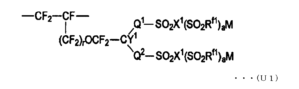
- the ion exchange membrane according to [1] which is a polymer having a structural unit represented by the formula (U1).
- Q 1 is a perfluoroalkylene group which may have an etheric oxygen atom
- Q 2 is a single bond or a perfluoroalkylene group which may have an etheric oxygen atom.
- R f1 is a perfluoroalkyl group which may have an etheric oxygen atom, X 1 is an oxygen atom, a nitrogen atom or a carbon atom, and when X 1 is an oxygen atom, a is 0 When X 1 is a nitrogen atom, a is 1, when X 1 is a carbon atom, a is 2, Y 1 is a fluorine atom or a monovalent perfluoro organic group, and r is 0 or 1 and M is a hydrogen atom, an alkali metal or a quaternary ammonium base. ]
- the ion exchange capacity of at least a part of the fluorinated polymer having a carboxylic acid type functional group constituting the layer (C) comprising the fluorinated polymer having a carboxylic acid type functional group is 0.5 to 2.0 meq /
- the ion exchange membrane according to any one of [1] to [4], wherein the layer (Sa) located on the cathode side of the reinforcing material is a layer composed of two or more layers.
- the layer (Sa) located on the cathode side of the reinforcing material the layer (Sa-1) located on the most cathode side when dried has a thickness of 1 to 55 ⁇ m, and the ion The ion exchange membrane according to [5], which is a layer made of a fluorine-containing polymer having a sulfonic acid type functional group with an exchange capacity of 0.9 to 1.25 meq / g.
- the ion exchange membrane according to any one of [1] to [7] further having an inorganic particle layer on the outermost surface of at least one surface.
- the method for producing an ion exchange membrane for alkaline chloride electrolysis according to any one of [1] to [8], wherein a group that can be converted into an ion exchange group in the reinforced precursor membrane is converted into an ion exchange group.
- the reinforcing cloth is composed of a reinforcing thread and a sacrificial thread.
- the reinforcing cloth in the reinforcing cloth is converted into an ion-exchange group by converting the group that can be converted into an ion-exchange group by bringing the reinforcing precursor film into contact with an alkaline aqueous solution.
- the manufacturing method according to [9] wherein at least a part of the reinforcing material is dissolved to form a reinforcing material.
- the production method according to [9] wherein the alkaline aqueous solution is a mixture of a water-soluble organic compound, an alkali metal hydroxide, and water.
- the ion exchange membrane for alkaline chloride electrolysis of the present invention is a membrane having a high water permeability and a low electrolysis voltage during electrolysis of an aqueous alkali chloride solution while minimizing the amount of water supplied to the cathode chamber, and has a high caustic alkali.
- a quality aqueous alkali hydroxide solution can be produced.
- the method for producing an ion exchange membrane for alkali chloride electrolysis of the present invention the amount of water permeation is large, the amount of water supplied to the cathode chamber is minimized, and the electrolysis voltage during electrolysis of the alkali chloride aqueous solution is low and high.
- An ion exchange membrane for alkaline chloride electrolysis capable of producing a caustic alkaline aqueous alkali hydroxide solution can be produced.
- the alkaline chloride electrolysis apparatus of the present invention can generate an alkaline hydroxide aqueous solution having a low caustic quality and a low electrolysis voltage during electrolysis of an alkaline chloride aqueous solution while minimizing the amount of water supplied to the cathode chamber.
- the method for producing an alkali hydroxide of the present invention can produce an aqueous alkali hydroxide solution having a low caustic quality and a low electrolysis voltage during electrolysis of an aqueous alkali chloride solution while minimizing the amount of water supplied to the cathode chamber. .
- the “ion exchange group” is a group that can exchange at least a part of ions contained in the group with other ions.
- the following carboxylic acid type functional groups, sulfonic acid type functional groups and the like can be mentioned.
- the “carboxylic acid type functional group” means a carboxy group (—COOH) or a carboxylate group (—COOM 1, where M 1 is an alkali metal or a quaternary ammonium base).
- the “sulfonic acid type functional group” means a sulfo group (—SO 3 H) or a sulfonate group (—SO 3 M 2, where M 2 is an alkali metal or a quaternary ammonium base).
- the “precursor membrane” is a membrane containing a polymer having a group that can be converted into an ion exchange group.
- the “group that can be converted into an ion exchange group” means a group that can be converted into an ion exchange group by a known treatment such as hydrolysis treatment or acidification treatment.
- the “group that can be converted into a carboxylic acid type functional group” means a group that can be converted into a carboxylic acid type functional group by a known process such as hydrolysis or acidification.
- the “group that can be converted into a sulfonic acid type functional group” means a group that can be converted into a sulfonic acid type functional group by a known treatment such as hydrolysis or acidification.
- the unit of the ion exchange capacity, “milli equivalent / gram dry resin”, may be described simply as “meq / g”.
- the “perfluorocarbon polymer” means a polymer in which all of hydrogen atoms bonded to carbon atoms in the polymer are substituted with fluorine atoms. Some of the fluorine atoms in the perfluorocarbon polymer may be substituted with one or both of chlorine atoms and bromine atoms.
- the “perfluoromonomer” means a monomer in which all of hydrogen atoms bonded to carbon atoms in the monomer are substituted with fluorine atoms.
- the “structural unit” means a polymerized unit derived from a monomer that is present in the polymer and constitutes the polymer.
- the structural unit when the structural unit is generated by addition polymerization of a monomer having a carbon-carbon unsaturated double bond, the structural unit is a divalent structural unit generated by cleavage of the unsaturated double bond.
- the structural unit may be a structural unit obtained by forming a polymer having a structure of a certain structural unit and then chemically converting the structural unit, for example, hydrolysis.
- a structural unit derived from an individual monomer may be described by a name in which “unit” is added to the monomer name.
- “Reinforcing material” means a material used to improve the strength of an ion exchange membrane.
- the reinforcing material is a material derived from the reinforcing cloth.
- the “reinforcing cloth” means a cloth used as a raw material for a reinforcing material for improving the strength of the ion exchange membrane.
- the “reinforcing yarn” is a yarn constituting the reinforcing cloth, and is made of a material that does not elute even when the reinforcing cloth is immersed in an alkaline aqueous solution (for example, a sodium hydroxide aqueous solution having a concentration of 32 mass%).
- the “sacrificial yarn” is a yarn constituting the reinforcing cloth, and is made of a material that elutes into the alkaline aqueous solution when the reinforcing cloth is immersed in the alkaline aqueous solution.
- “Elution hole” means a hole formed as a result of the sacrificial yarn being eluted in an alkaline aqueous solution.
- the “reinforced precursor film” means a film in which a reinforcing cloth is disposed in the precursor film.
- the ion exchange membrane for alkaline chloride electrolysis of the present invention comprises a layer (hereinafter also referred to as layer (C)) composed of a fluorine-containing polymer having a carboxylic acid type functional group (hereinafter also referred to as fluorine-containing polymer (C)).
- a reinforcing material having a layer (hereinafter also referred to as a layer (S)) composed of a fluorine-containing polymer having a sulfonic acid type functional group (hereinafter also referred to as a fluorine-containing polymer (S)), and a reinforcing material including a reinforcing yarn is a layer ( S).
- the reinforcing material may include a sacrificial yarn in addition to the reinforcing yarn.
- elution holes may be formed by elution of sacrificial yarn.
- FIG. 1 is a schematic cross-sectional view showing an example of an ion exchange membrane for alkaline chloride electrolysis according to the present invention.
- the ion exchange membrane 1 for alkali chloride electrolysis (hereinafter also referred to as ion exchange membrane 1) is obtained by reinforcing an electrolyte membrane 10 made of a fluorine-containing polymer having an ion exchange group with a reinforcing material 20.
- the electrolyte membrane 10 is a laminate composed of a layer (C) 12 and a layer (S) 14.
- a reinforcing member 20 including a reinforcing yarn is disposed in the layer (S) 14.
- the thickness of each layer when the ion exchange membrane 1 is dried is obtained by drying the ion exchange membrane at 90 ° C. for 4 hours, observing the cross section of the ion exchange membrane with an optical microscope, and using image software as described later. .
- the thickness of the layer is measured at a position where neither the reinforcing thread nor the sacrificial thread constituting the reinforcing cloth or the reinforcing material is present.
- the layer (C) 12 is preferably a layer made of only the fluoropolymer (C) that does not contain a material other than the fluoropolymer (C) from the viewpoint of electrolytic performance.
- the layer (C) 12 is shown as a single layer, but may be a layer formed of a plurality of layers.
- the types of structural units constituting the fluoropolymer (C) and the proportions of the structural units having a carboxylic acid type functional group may be different.
- the thickness of the layer (C) 12 when dried is 9 to 28 ⁇ m, and preferably 9 to 22 ⁇ m.
- the thickness of the layer (C) affects the water permeability of the ion exchange membrane as well as the ion exchange capacity. In particular, when the thickness of the layer (C) is thin, the water permeability of the ion exchange membrane increases. On the other hand, the thickness of the layer (C) has a great influence on the caustic quality of the aqueous alkali hydroxide solution obtained by electrolysis together with the ion exchange capacity.
- the thickness of the layer (C) When the thickness of the layer (C) is small, the amount of water permeation through the ion exchange membrane is high, but chlorine ions easily permeate through the ion exchange membrane, and the concentration of chlorine ions in the resulting aqueous alkali hydroxide solution increases. It is important for maintaining the high caustic quality that the thickness of the layer (C) 12 is not less than the lower limit. On the other hand, the layer (C) has a great influence on the electrolysis voltage, and when the thickness is thick, the electrolysis voltage increases greatly. That is, when the thickness of the layer (C) 12 at the time of drying is not more than the above upper limit value, the membrane resistance of the ion exchange membrane 1 can be suppressed low, and it is important for suppressing an increase in electrolytic voltage.
- the fluoropolymer (C) constituting the layer (C) 12 preferably has an ion exchange capacity of 0.5 to 2.0 meq / g, more preferably 0.6 to 2.0 meq / g, and 7 to 2.0 meq / g is more preferable.
- the layer (C) 12 is formed of a plurality of layers, it is preferable that the ion exchange capacity of all the fluoropolymers (C) constituting the layer (C) 12 is in the above range.
- the layer (C) 12 consists of a single layer, and the ion exchange capacity of the polymer constituting the layer is in the above range.
- the ion exchange capacity of the fluoropolymer (C) is at least the lower limit value, the electric resistance of the ion exchange membrane when electrolyzing an alkali chloride aqueous solution is lowered, and an ion exchange membrane having a low electrolysis voltage is obtained.
- the ion exchange capacity of the fluoropolymer (C) is not more than the above upper limit, the synthesis of the fluoropolymer (C) having a high molecular weight is easy, and the mechanical strength of the layer (C) 12 can be increased. Further, an excessive swelling of the fluoropolymer (C) can be suppressed, and an ion exchange membrane in which current efficiency is unlikely to be reduced can be obtained.
- the ion exchange capacity of the fluoropolymer (C) constituting the layer (C) 12 as described above affects the water permeability of the ion exchange membrane together with its thickness. If the ion exchange capacity of the fluoropolymer (C) is not less than the lower limit, water that has passed through a layer (S) described later is sufficiently permeated and the water permeability is unlikely to decrease.
- the layer (C) 12 is a layer (hereinafter also referred to as a layer (C ′)) made of a fluoropolymer having a group that can be converted into a carboxylic acid type functional group, which constitutes a reinforced precursor film described later.
- Layer (C) 12 is preferably formed through step (ib). That is, the fluorine-containing polymer (C) constituting the layer (C) 12 is a carboxylic acid-type functional group of a fluorine-containing polymer having a group that can be converted into a carboxylic acid-type functional group described later in step (ib) described later. It is preferably obtained by converting a group that can be converted into a group into a carboxylic acid type functional group.
- the fluorine-containing polymer (C) is, for example, a copolymer constituting the layer (C ′), a group that can be converted into a carboxylic acid type functional group and a monomer having a fluorine atom (hereinafter referred to as a fluorine-containing monomer (C ′)).
- the fluorine-containing polymer converted into is preferable.
- the fluorine-containing monomer (C ′) is a monomer having one or more fluorine atoms in the molecule, an ethylenic double bond, and a group that can be converted into a carboxylic acid type functional group, It is not limited, A conventionally well-known thing can be used.
- the fluorine-containing monomer (C ′) those represented by the following formula (1) are preferable from the viewpoint of excellent production costs, reactivity with other monomers, and properties of the resulting fluorine-containing polymer.
- CF 2 CF- (O) p- (CF 2 ) q- (CF 2 CFX) r- (O) s- (CF 2 ) t- (CF 2 CFX ') u -A 1 (1)
- X and X ′ are each independently a fluorine atom or a trifluoromethyl group.
- a 1 is a group that can be converted into a carboxylic acid type functional group. Specifically, —CN, —COF, —COOR 1 (R 1 is an alkyl group having 1 to 10 carbon atoms), —COONR 2 R 3 (R 2 and R 3 are each independently hydrogen Or an alkyl group having 1 to 10 carbon atoms).
- p is 0 or 1.
- q is an integer of 0 to 12.
- r is an integer of 0 to 3.
- s is 0 or 1.
- t is an integer of 0 to 12.
- u is an integer of 0 to 3.
- p and s are not 0 simultaneously, and r and u are not 0 simultaneously. That is, 1 ⁇ p + s and 1 ⁇ r + u.
- fluorinated olefin examples include fluoroolefins having 2 to 3 carbon atoms having one or more fluorine atoms in the molecule.
- TFE is particularly preferable from the viewpoints of monomer production cost, reactivity with other monomers, and excellent properties of the resulting fluoropolymer.
- Fluorine-containing olefins may be used alone or in combination of two or more.
- CFR f where R f is a perfluoroalkyl group having 2 to 10 carbon atoms
- CF 2 CF-OR f1 (where R f1 is 1 to 10 carbon atoms)
- CF 2 ⁇ CFO (CF 2 ) v CF ⁇ CF 2 where v is an integer of 1 to 3
- the ion exchange capacity of the fluoropolymer (C) can be adjusted by changing the content of the structural unit derived from the fluoromonomer (C ′) in the fluoropolymer (C ′).
- the content of the carboxylic acid type functional group in the fluoropolymer (C) is preferably the same as the content of the group that can be converted to the carboxylic acid functional group in the fluoropolymer (C ′).
- the TQ value of the fluoropolymer (C) is preferably 150 ° C. or higher, more preferably 170 to 340 ° C., and even more preferably 170 to 300 ° C., from the viewpoint of mechanical strength and film-forming property as an ion exchange membrane.
- the TQ value is a value related to the molecular weight of the polymer, and is indicated by a temperature at which the volume flow rate indicates 100 mm 3 / sec.
- the volume flow rate is the amount of polymer flowing out in units of mm 3 / sec when the polymer is melted and discharged from an orifice (diameter: 1 mm, length: 1 mm) at a constant temperature under a pressure of 3 MPa. is there.
- a higher TQ value indicates a higher molecular weight.
- the layer (S) 14 is preferably a layer made of only the fluoropolymer (S) containing no material other than the fluoropolymer (S) from the viewpoint of electrolytic performance.
- a reinforcing material 20 is disposed in the layer (S) 14 in order to increase the mechanical strength of the ion exchange membrane 1.
- the layer located on the cathode side from the reinforcing material 20 is the layer (Sa) 14A
- the layer located on the anode side from the reinforcing material 20 is the layer (Sb) 14B.
- the layers 14 ⁇ / b> A and 14 ⁇ / b> B are shown as single layers, but may be formed of a plurality of layers.
- the constitutional units constituting the fluoropolymer (S) and the proportions of the constitutional units having a sulfonic acid type functional group are different. It is good.
- the thickness of the layer 14A at the time of drying (the total when the layer 14A is formed of a plurality of layers) is 40 to 110 ⁇ m, preferably 50 to 90 ⁇ m, and more preferably 60 to 90 ⁇ m.
- the thickness is equal to or greater than the lower limit, the mechanical strength of the ion exchange membrane 1 is sufficiently high.
- the thickness is equal to or less than the upper limit, the membrane resistance of the ion exchange membrane 1 is low. In order to achieve both mechanical strength and electrolytic voltage, it is very important that the thickness is within the above range.
- the layer (Sa) 14A includes a layer made of a fluorine-containing polymer (S) having a sulfonic acid type functional group having an ion exchange capacity of 0.9 to 1.25 meq / g.
- the ion exchange capacity of the fluorine-containing polymer (S) having a sulfonic acid type functional group forming the layer contained in the layer (Sa) 14A is preferably 1.0 to 1.25 meq / g, and preferably 1.0 to 1.1 meq. / G is more preferable.
- the layer (Sa) 14A is formed of a plurality of layers, it is preferable that the ion exchange capacity of all the fluoropolymers (S) constituting the layer (Sa) 14A is in the above range.
- the layer (Sa) 14A is preferably composed of a plurality of layers, and more preferably composed of two layers. In another embodiment, the layer (Sa) 14A is preferably a single layer.
- the ion exchange capacity of the fluoropolymer (S) contained in the layer (Sa) 14A is not less than the lower limit, excessive swelling of the fluoropolymer (S) can be suppressed, and the electrical resistance of the ion exchange membrane is low, The electrolysis voltage when electrolyzing an alkali chloride aqueous solution is low.
- the fluorine-containing polymer (S) having an ion exchange capacity equal to or less than the upper limit can easily increase the molecular weight of the fluorine-containing polymer (S) during polymerization.
- the mechanical strength of the layer (Sa) is high.
- the thickness of the layer (Sb) 14B at the time of drying (when the layer 14B is composed of a plurality of layers) is 6 to 100 ⁇ m, preferably 6 to 50 ⁇ m, more preferably 10 to 40 ⁇ m, and more preferably 15 to 35 ⁇ m. Further preferred. If the thickness of the layer 14B is too thin, the reinforcing material immediately below the layer 14B is positioned very close to the surface of the ion exchange membrane, and the peel resistance and mechanical strength are low. Therefore, if the thickness of 14B is equal to or greater than the lower limit, the reinforcing material 20 is disposed at an appropriate depth from the surface of the electrolyte membrane 10, and the reinforcing material 20 has excellent peeling resistance.
- the mechanical strength is excellent.
- the membrane resistance is also increased. Therefore, if the thickness of the layer 14B is equal to or less than the upper limit value, the membrane resistance is low, and an increase in electrolytic voltage can be suppressed.
- the layer (Sb) 14B includes a layer made of a fluorine-containing polymer (S) having a sulfonic acid type functional group having an ion exchange capacity of 1.3 to 2.5 meq / g.
- the ion exchange capacity of the fluoropolymer (S) having a sulfonic acid type functional group forming the layer 4B is preferably 1.3 to 2.2 meq / g, and more preferably 1.3 to 2.0 meq / g.
- the layer 14B is formed of a plurality of layers, it is preferable that the ion exchange capacity of the fluoropolymer (S) constituting the layer located at least on the anode side is in the above range, and constitutes the layer 14B.
- the ion exchange capacity of all the fluoropolymers (S) is in the above range.
- the layer 14B consists of a single layer, and the ion exchange capacity of the fluoropolymer (S) constituting the layer is in the above range.
- the water permeability of the ion exchange membrane is more affected by the ion exchange capacity of the layer (Sb) than the ion exchange capacity of the layer (C) and the ion exchange capacity of the layer (Sa). .
- the ion exchange capacity of the fluorine-containing polymer (S) contained in the layer (Sb) 14B is not less than the lower limit value, the water permeability of the ion exchange membrane is high, and the concentration distribution of the catholyte in the cathode chamber of the electrolytic cell is high. As a result, the electrolytic efficiency can be maintained high. If the ion exchange capacity of the fluoropolymer (S) contained in the layer (Sb) 14B is not more than the upper limit, as described above, the fluoropolymer (S) has a high molecular weight and high mechanical strength. Strength can be maintained, and membrane breakage during electrolytic operation or membrane mounting can be suppressed.
- At least part of the fluorine-containing polymer having a sulfonic acid type functional group constituting the layer (Sb) 14B has a constitutional unit based on a fluorine-containing monomer having two or more, preferably two sulfonic acid type functional groups.
- a polymer is preferred. By doing in this way, ion exchange group content per fluorine-containing monomer unit becomes high. Therefore, a layer (Sb) having a higher ion exchange capacity can be formed even with a small content of the fluorine-containing monomer unit as compared with the fluorine-containing polymer having a fluorine-containing monomer unit having only one sulfone-type functional group.
- a structural unit based on a fluorine-containing monomer having two or more sulfonic acid type functional groups a structural unit represented by the following formula (U1) is preferable.
- the meaning of each symbol in the formula (U1) is as described above. Among these, it is preferable.
- X 1 is preferably an oxygen atom
- Y 1 is preferably a fluorine atom.
- An organic group means a group containing one or more carbon atoms.
- the layer (Sa) 14A is a layer (hereinafter also referred to as layer (S′a)) made of a fluoropolymer having a group that can be converted into a sulfonic acid type functional group, which constitutes a reinforced precursor film described later.
- the layer (Sa) 14A is preferably applied to the step (ib).
- the layer (Sb) 14B is a layer made of a fluorine-containing polymer having a group that can be converted into a sulfonic acid-type functional group (hereinafter, also referred to as layer (S′b)), which constitutes a reinforced precursor film described later.
- the layer (Sb) 14B is preferably formed through the step (ib) described later.
- the fluoropolymer (S) constituting the layer (S) including the layer (Sa) and the layer (Sb) is a group that can be converted into a sulfonic acid type functional group described later in the step (ib) described later. It is preferably obtained by converting a group capable of being converted into a sulfonic acid type functional group of a fluorine-containing polymer having a sulfonic acid type functional group.
- Examples of the fluorine-containing polymer (S) include a monomer having a group capable of being converted to a sulfonic acid type functional group and a fluorine atom, which is a copolymer constituting the layer (S′a) and the layer (S′b) (hereinafter, A group that can be converted to a sulfonic acid type functional group in a copolymer of fluorine-containing olefin (S ′)) and a fluorine-containing olefin (hereinafter also referred to as fluorine-containing polymer (S ′)).
- a fluorine-containing polymer converted into a sulfonic acid type functional group by a decomposition treatment or the like is preferable.
- the fluorine-containing monomer (S ′) is a monomer having one or more fluorine atoms in the molecule, an ethylenic double bond, and a group that can be converted into a sulfonic acid type functional group, It does not specifically limit and a well-known thing can be used.
- the fluorine-containing monomer (S ′) is represented by the following formula (2) or the following formula (3) from the viewpoint of excellent production cost of the monomer, reactivity with other monomers, and characteristics of the resulting fluorine-containing polymer. A fluorine-containing monomer is preferred.
- R f2 is a perfluoroalkyl group having 1 to 20 carbon atoms, may contain an etheric oxygen atom, and may be linear or branched.
- a 2 is a group that can be converted into a sulfonic acid type functional group. Specifically, —SO 2 F, —SO 2 Cl, —SO 2 Br and the like are included.
- w is an integer of 1 to 8
- x is an integer of 1 to 5.
- fluorine-containing monomer represented by the formula (3) examples include CF 2 ⁇ CF— (CF 2 ) w —SO 2 F, CF 2 ⁇ CF—CF 2 —O— (CF 2 ) w —SO 2. F.
- w is an integer of 1 to 8.
- CF 2 CF-O-CF 2 CF 2 -SO 2 F
- CF 2 CF-O-CF 2 CF 2 CF 2 -SO 2 F
- CF 2 CF-O-CF 2 CF 2 CF 2 CF 2 - SO 2 F
- CF 2 ⁇ CF—CF 2 CF 2 —SO 2 F CF 2 ⁇ CF—CF 2 CF 2 —SO 2 F
- CF 2 ⁇ CF—CF 2 CF 2 —SO 2 F CF 2 ⁇ CF—CF 2 CF 2 —SO
- the layer (Sb) contains a fluorine-containing polymer having a constitutional unit based on a fluorine-containing monomer having two or more sulfonic acid type functional groups, as the fluorine-containing monomer (S ′), at least one fluorine in the molecule
- a fluorine-containing monomer having an atom, an ethylenic double bond, and two or more groups that can be converted into a sulfonic acid type functional group can be used.
- a fluorine-containing monomer a fluorine-containing monomer from which the structural unit of the above formula (U1) can be obtained is preferable.
- fluorine-containing monomer those represented by the following formula (m1) are preferable, and specifically, those represented by the following formula (m11), the following formula (m12), or the following formula (m13) are more preferable.
- r is 0 or 1
- R F11 is a single bond or a linear perfluoroalkylene group having 1 to 6 carbon atoms which may have an etheric oxygen atom.
- R F12 is a linear perfluoroalkylene group having 1 to 6 carbon atoms.
- Q 2 in the formula (U1) is OCF 2 R F12 (perfluoroalkylene group which may have an etheric oxygen atom)
- Q 1 is R F11 (single bond or perfluoroalkylene group which may have an etheric oxygen atom)
- SO 2 X 1 (SO 2 R f1 ) a M hydrolyzes SO 2 F or SO 2 F obtained by treating treatment or acid form sulfonic acid functional group
- X 1 is an oxygen atom
- a is 0, M is hydrogen, an alkali metal or a quaternary ammonium salt.
- Y 1 is a structural unit in which a fluorine atom is present.
- fluorine-containing olefin examples include those exemplified above, and TFE is particularly preferable from the viewpoint of production cost, reactivity with other monomers, and excellent properties of the obtained fluorine-containing polymer.
- TFE is particularly preferable from the viewpoint of production cost, reactivity with other monomers, and excellent properties of the obtained fluorine-containing polymer.
- One type of fluorine-containing olefin may be used, or two or more types may be used in combination.
- the fluorine-containing polymer (S ′) in addition to the fluorine-containing monomer (S ′) and the fluorine-containing olefin, another monomer may be used.
- the other monomer include those exemplified above.
- the proportion of other monomers is preferably 30 mol% or less of the total structural units (100 mol%) in the fluoropolymer (S ′) from the viewpoint of maintaining ion exchange performance.
- the ion exchange capacity of the fluoropolymer (S) can be adjusted by changing the content of the structural unit derived from the fluoromonomer (S ′) in the fluoropolymer (S ′).
- the content of the sulfonic acid type functional group in the fluoropolymer (S) is preferably the same as the content of the group that can be converted to the sulfonic acid functional group in the fluoropolymer (S ′).
- the TQ value of the fluoropolymer (S ′) is preferably 150 ° C. or higher, more preferably 170 to 340 ° C., and further preferably 170 to 300 ° C. from the viewpoint of mechanical strength and film-forming property as an ion exchange membrane.
- the layer in contact with the layer (C) 12 is the layer (Sa-1) 14Aa (hereinafter referred to as layer (Sa-1)
- the layer in contact with the layer (Sb) 14B is the layer (Sa-2) 14Ab (hereinafter also referred to as layer (Sa-2)).
- the layer 14Aa From the viewpoint of adhesiveness, the ion exchange capacity of the fluoropolymer (S) constituting the layer (Sa-1) is lower than the ion exchange capacity of the fluoropolymer (S) constituting the layer (Sa-2).
- the ion exchange capacity of the layer (Sa-1) is preferably 0.9 to 1.25 meq / g, more preferably 0.9 to 1.15 meq / g.
- the ion exchange capacity of the fluoropolymer (S) constituting the layer (Sa-1) is close to the ion exchange capacity of the fluoropolymer (C) constituting the layer (C). preferable.
- the difference between the ion exchange capacity of the fluoropolymer (S) constituting the layer (Sa-1) and the ion exchange capacity of the fluoropolymer (C) constituting the layer (C) is 0. 5 millimeq / g or less is preferable, and 0.35 meq / g is more preferable.
- the thickness of the layer (Sa-1) at the time of drying may be an appropriate thickness that contributes to adhesion, and is preferably 1 to 55 ⁇ m, and more preferably 1 to 40 ⁇ m.
- the reinforcing material 20 is a material that reinforces the electrolyte membrane 10 and is derived from a reinforcing cloth.
- the reinforcing fabric is composed of warp and weft, and the warp and weft are preferably orthogonal.
- the reinforcing cloth is preferably composed of a reinforcing yarn and a sacrificial yarn.
- the reinforcing yarn is a yarn made of a material that does not elute even when the reinforced precursor film is immersed in an alkaline aqueous solution. Even after the sacrificial yarn is immersed in an alkaline aqueous solution and the sacrificial yarn is eluted from the reinforcing fabric, it remains without dissolving as a yarn constituting the reinforcing material, maintaining the mechanical strength and dimensional stability of the ion exchange membrane. Contribute to.
- a yarn containing a perfluorocarbon polymer is preferable, a yarn containing PTFE is more preferable, and a yarn made of only PTFE is more preferable.
- the sacrificial yarn is a yarn from which at least a part thereof is eluted by immersing the reinforced precursor film in an alkaline aqueous solution.
- the sacrificial yarn prevents misalignment when weaving the reinforcing cloth, and at least part of the sacrificial yarn is eluted from the reinforced precursor film, thereby reducing the electric resistance of the ion exchange membrane and lowering the electrolysis voltage.
- the sacrificial yarn may be a monofilament or a multifilament.
- a PET yarn made only of PET As the sacrificial yarn 24, a PET yarn made only of PET, a PET / PBT yarn made of a mixture of PET and polybutylene terephthalate (PBT), a PBT yarn made only of PBT, or a PTT yarn made only of polytrimethylene terephthalate (PTT). Is preferable, and PET yarn is more preferable.
- the ion exchange membrane for alkaline chloride electrolysis of the present invention is produced through the following step (i), and then placed in an electrolytic cell in the following step (ii).
- the reinforcing fabric is composed of reinforcing yarn and sacrificial yarn
- at least a part of the sacrificial yarn of the reinforcing fabric in the reinforcing precursor film is eluted when the reinforcing fabric is brought into contact with the alkaline aqueous solution in the step (i).
- the reinforcing material 20 is composed of the reinforcing yarn 22 and the remaining undissolved sacrificial yarn 24 when part of the sacrificial yarn 24 is dissolved, and is composed of only the reinforcing yarn 22 when the entire sacrificial yarn 24 is dissolved.
- At least part of the sacrificial yarn 24 is eluted in the step (i), and as a result, the elution hole 28 is formed. Since the ion exchange membrane obtained through the step (i) is subjected to the step (ii), the sacrificial yarn in the step (ii) can be obtained even if the sacrificial yarn 24 remains undissolved in the step (i). 24, most of the remainder of the material, preferably all is eluted and removed in the alkaline aqueous solution.
- the ion exchange membrane 1 As shown in FIG. 1, a part of the sacrificial yarn 24 remains even after the step (i), and an elution hole 28 is formed around the remaining melted filament 26 of the sacrificial yarn 24. It is preferable. Thus, when the ion exchange membrane 1 is handled after the production of the ion exchange membrane 1 and before the conditioning operation of alkaline chloride electrolysis, or when the ion exchange membrane 1 is installed in the electrolytic cell during the conditioning operation, the ion exchange membrane 1 is less susceptible to breakage such as cracks.
- the sacrificial yarn 24 Even if part of the sacrificial yarn 24 remains after the step (i), the sacrificial yarn 24 elutes into the alkaline aqueous solution during the step (ii), and most, preferably all, is removed. At the time of the main operation of alkali chloride electrolysis using the membrane 1, the membrane resistance is not affected. After the ion exchange membrane 1 is disposed in the electrolytic cell, no great force is applied to the ion exchange membrane 1 from the outside. Therefore, even if the sacrificial yarn 24 is completely eluted and removed from the alkaline aqueous solution, the ion exchange membrane 1 is not easily damaged such as cracks. In the step (i), all of the sacrificial yarn 24 may be eluted.
- the ion exchange membrane 1 may further include an inorganic particle layer (not shown) on one or both of its outermost surfaces.
- the inorganic particle layer is preferably provided on at least one of the outermost surfaces of the ion exchange membrane 1, and more preferably provided on both.
- the inorganic particle layer is provided in order to suppress adhesion of gas generated by alkali chloride electrolysis to the surface of the ion exchange membrane 1 and to suppress an increase in electrolytic voltage.
- the inorganic particle layer includes inorganic particles and a binder.
- the inorganic particles those having excellent corrosion resistance to an alkali chloride or alkali hydroxide aqueous solution and having hydrophilicity are preferable.
- at least one selected from the group consisting of oxides, nitrides, and carbides of Group 4 elements or Group 14 elements is preferable.
- SiO 2 , SiC, ZrO 2 , or ZrC is more preferable, and ZrO 2 is particularly preferable.
- the average particle diameter of the inorganic particles is preferably 0.5 to 1.5 ⁇ m, more preferably 0.7 to 1.3 ⁇ m.
- the average particle diameter is not less than the lower limit, a high gas adhesion suppressing effect can be obtained.
- the average particle size is not more than the above upper limit value, the inorganic particles are excellent in drop-off resistance.
- the average particle size of the inorganic particles is observed with a scanning electron microscope (SEM), and image size measurement / measurement software (Pixs2000 PRO manufactured by Innotech Co., Ltd.) is used for 30 minimum particles in the SEM observation image. The particle diameter is measured and the average value is shown.
- a fluorine-containing polymer having a carboxy group or a sulfo group is preferable, and a fluorine-containing polymer having a sulfo group is more preferable.
- the fluorine-containing polymer may be a homopolymer of a monomer having a carboxy group or a sulfo group, or may be a copolymer of a monomer having a carboxy group or a sulfo group and a monomer copolymerizable with the monomer.
- the mass ratio (binder ratio) of the binder to the total mass of the inorganic particles and the binder in the inorganic particle layer is preferably 0.15 to 0.3, more preferably 0.15 to 0.25, and 0.16 to 0.20. Is more preferable.
- the binder ratio is equal to or higher than the lower limit, the inorganic particles are excellent in the drop-off resistance.
- the binder ratio is not more than the above upper limit value, a high gas adhesion suppressing effect can be obtained.
- the ion exchange membrane for alkaline chloride electrolysis of the present invention is produced through the step (i), and the step (i) preferably includes the following steps (ia) and (ib).
- the reinforced precursor film includes a layer made of a fluorine-containing polymer having a group that can be converted into a carboxylic acid type functional group (C ′), and a layer made of a fluorine-containing polymer having a group that can be converted into a sulfonic acid type functional group (S′a) , A reinforcing cloth, and a layer (S′b) composed of a fluorine-containing polymer having a group that can be converted into a sulfonic acid type functional group can be produced. That is, when a precursor film is laminated to produce a reinforced precursor film, it can be produced by laminating with a reinforcing cloth.
- the precursor film may be a film made of a single layer of a fluoropolymer having a group that can be converted into an ion exchange group, or may be a film made of a plurality of layers.
- a layer (C ′) comprising a fluorine-containing polymer having a group that can be converted into a carboxylic acid type functional group, and a fluorine-containing group having a group that can be converted into a sulfonic acid type functional group.
- a laminated film having a polymer layer (S′a) is obtained by a coextrusion method.
- a film composed of a layer (S′b) made of a fluoropolymer having a group that can be converted into a sulfonic acid type functional group by a single layer extrusion method (hereinafter also referred to as a film (S′b)) is obtained.
- the film (S′b), the reinforcing cloth, and the laminated film are arranged in this order, and these are laminated using a laminating roll or a vacuum laminating apparatus.
- the laminated film is arranged so that the layer (S′a) side is in contact with the reinforcing cloth.
- the reinforced precursor film thus obtained is laminated in the order of the layer (S′b), the reinforcing cloth, the layer (S′a), and the layer (C ′).
- the layer (C ′), the layer (S′a), and the layer (S′b) are converted into the layer (C), the layer (Sa), and the layer (Sb), respectively, in the step (ib) described later. Is done. Further, the thickness of the layer (C), the layer (Sa) and the layer (Sb) in the ion exchange membrane when dried, and the layer (C ′), the layer (S′a) and the layer (S′b) in the reinforced precursor film are also shown. ) Has a relation of the following formula (I).
- a film made of a layer made of a fluorine-containing polymer having a group that can be converted into a sulfonic acid type functional group is separately obtained, and the gap between the reinforcing cloth and the laminated film is obtained.
- step (ib) a group that can be converted into an ion exchange group of the strengthened precursor film by contacting the strengthened precursor film obtained in step (ia) with an alkaline aqueous solution is converted into an ion exchange group.
- at least a part of the sacrificial yarn of the reinforcing precursor film is eluted to obtain an ion exchange membrane for alkaline chloride electrolysis.
- the conversion of the ion exchange group is preferably carried out by a method using a mixture of a water-soluble organic compound, an alkali metal hydroxide and water, as described in, for example, JP-A-1-140987. .
- the water-soluble organic compound include dimethyl sulfoxide and ethanol.
- the alkali metal hydroxide include potassium hydroxide and sodium hydroxide.
- the layer (C ′) is converted into the layer (C) 12
- the layer (S′a) is converted into the layer (Sa) 14 A
- the layer (S′b) is converted into the layer ( Sb) respectively converted to 14B.
- the layer (Sa) 14A is composed of a plurality of layers, for example, when it is composed of two layers, as shown in FIG. 2, the layer (Sa-1) 14Aa and the layer (Sa-2) 14Ab are composed of layers (Sa). 14A is configured, and the layer (S) 14 is configured together with the layer (Sb) 14B.
- the elution of the sacrificial yarn is preferably performed by hydrolyzing the material constituting the sacrificial yarn.
- FIG. 3 is a schematic view showing an example of the alkali chloride electrolysis apparatus of the present invention.
- an alkaline chloride electrolysis apparatus 100 performs electrolysis so that an electrolytic cell 110 including a cathode 112 and an anode 114, an electrolytic cell 110 is divided into a cathode chamber 116 on the cathode 112 side and an anode chamber 118 on the anode 114 side.
- an ion exchange membrane 1 mounted in the tank 110.
- the ion exchange membrane 1 is mounted in the electrolytic cell 110 such that the layer (C) 12 is on the cathode 112 side and the layer (S) 14 is on the anode 114 side.
- the cathode 112 may be disposed in contact with the ion exchange membrane 1 or may be disposed with a gap between the cathode 112 and the ion exchange membrane 1.
- a material constituting the cathode chamber 116 a material resistant to alkali hydroxide and hydrogen is preferable. Examples of the material include stainless steel and nickel.
- the material constituting the anode chamber 118 is preferably a material resistant to alkali chloride and chlorine. Examples of the material include titanium.
- the base material for the cathode is preferably stainless steel or nickel from the viewpoints of resistance to alkali hydroxide and hydrogen, workability, and the like.
- As the anode base material titanium or the like is preferable from the viewpoints of resistance to alkali chloride and chlorine, workability, and the like.
- the surface of the electrode substrate is preferably coated with, for example, ruthenium oxide, iridium oxide or the like.
- the manufacturing method of the alkali hydroxide of the present invention can adopt a known mode except that it is performed by the alkali chloride electrolysis apparatus of the present invention.
- the sodium chloride aqueous solution is supplied to the anode chamber 118 of the alkali chloride electrolysis apparatus 100, the sodium hydroxide aqueous solution is supplied to the cathode chamber 116, and the cathode chamber.
- the sodium chloride aqueous solution is electrolyzed while maintaining the concentration of the sodium hydroxide aqueous solution discharged from 116 at a predetermined concentration (for example, 32% by mass).
- the object of the present invention is achieved as described below.
- the thickness of the layer (C) is reduced or the ion exchange capacity is increased, the amount of chloride ions that permeate the ion exchange membrane also increases. As a result, the caustic quality of the aqueous alkali hydroxide solution decreases.
- the characteristics of the layer (Sb) located on the anode side with respect to the reinforcing material, particularly the fluorine-containing polymer constituting the layer (Sb) have a great influence on the water permeability, and by setting these to a specific range, a sufficient water permeability can be secured and the electrolysis voltage can be lowered.
- the thickness of the layer (C) has a great influence on the amount of chloride ions permeating the ion exchange membrane together with the ion exchange capacity, the thickness of the layer (C) can be obtained within a specific range.
- the caustic alkali quality of the resulting aqueous alkali hydroxide solution can be improved, and the electrolysis voltage can be lowered.
- the ion exchange capacity and thickness of the layer (Sb) are in a specific range, and the thickness of the layer (C) and the ion exchange capacity and thickness of the layer (Sa) are also specified.
- TQ value was determined as a temperature indicating a capacity flow rate: 100 mm 3 / sec.
- the capacity flow rate was measured when Shimadzu flow tester CFD-100D (manufactured by Shimadzu Corporation) was used and the target polymer was melted and flowed out from an orifice (diameter: 1 mm, length: 1 mm) at a constant temperature under a pressure of 3 MPa.
- the amount of polymer to be used (mm 3 / sec).
- This ratio is defined as the ratio of the structural unit having a carboxylic acid type functional group or a sulfonic acid type functional group in the fluoropolymer obtained after the hydrolysis treatment, and the ion exchange capacity is obtained using a sample having a known ion exchange capacity as a calibration curve. It was. Note that the above measurement can be performed regardless of whether the ion exchange group is an acid type, a potassium type or a sodium type.
- the thickness of each layer at the time of drying in the ion exchange membrane was determined by drying the ion exchange membrane at 90 ° C. for 4 hours, observing the cross section of the ion exchange membrane with an optical microscope, and using image software (Pixs2000 PRO manufactured by Innotech). Asked.
- the thickness of each layer is a thickness at a position where the reinforcing yarn and the sacrificial yarn constituting the reinforcing material do not exist.
- the ion exchange membrane is placed in a test electrolytic layer having a rectangular shape with a length of 150 mm ⁇ width of 100 mm so that the layer (C) faces the cathode, and sodium hydroxide concentration in the cathode chamber: 32% by mass, anode Sodium chloride aqueous solution was electrolyzed under the conditions of indoor sodium chloride concentration: 200 g / L, temperature: 90 ° C., current density: 6 kA / m 2 , and the electrolysis voltage (V) and current efficiency (from 3 to 10 days after the start of operation) %), The sodium chloride concentration in the produced aqueous alkali hydroxide solution was determined. From the amount of water added to the catholyte and the current efficiency at this time, the water permeation amount was calculated as the molar amount ratio (mol / mol) of water moved per mol of sodium ions.
- the caustic quality is determined by titration with an aqueous solution of silver nitrate using an aqueous solution of potassium nitrate as an indicator and an amount of alkali chloride with respect to the alkali hydroxide in the aqueous solution of alkali hydroxide obtained by electrolysis. It was expressed as a fraction (unit: ppm). (Mass of alkali chloride in alkali hydroxide aqueous solution / mass of alkali hydroxide in alkali hydroxide aqueous solution) ⁇ 1000000
- Example 1 As a fluorine-containing polymer for forming the layer (C ′), a fluorine-containing polymer having a group that can be converted into a carboxylic acid type functional group by copolymerizing TFE and a fluorine-containing monomer represented by the following formula (X): Ion exchange capacity after hydrolysis: 1.08 meq / g, hereinafter referred to as polymer C) was synthesized.
- CF 2 CF—O—CF 2 CF 2 CF 2 —COOCH 3 (X)
- Fluoropolymer having a group that can be converted into a sulfonic acid type functional group by copolymerizing TFE and a fluorinated monomer represented by the following formula (Y) as a fluorinated polymer forming the layer (S′a) (Ion exchange capacity after hydrolysis: 1.1 meq / g, hereinafter referred to as polymer S1) was synthesized.
- CF 2 CF—O—CF 2 CF (CF 3 ) —O—CF 2 CF 2 —SO 2 F (Y)
- a fluorine-containing polymer for forming the layer (S′b) As a fluorine-containing polymer for forming the layer (S′b), a fluorine-containing polymer having a group that can be converted into a sulfonic acid type functional group by copolymerizing TFE and a fluorine-containing monomer represented by the formula (Y) ( Ion exchange capacity after hydrolysis: 1.25 meq / g, hereinafter referred to as polymer S2) was synthesized.
- Polymer C and polymer S1 are molded by a melt coextrusion method, and a layer (C′1) (thickness: 12 ⁇ m) made of polymer C and a layer (S′1) (thickness: 68 ⁇ m) made of polymer S1 A film A having a layer structure was obtained.
- the polymer S2 was molded by a melt extrusion method to obtain a film B having a layer (S′2) (thickness: 30 ⁇ m) made of the polymer S2. After rapidly stretching the PTFE film, a monofilament obtained by slitting to a thickness of 100 denier was used as a reinforcing yarn.
- a sacrificial yarn was a PET yarn made of 30-denier multifilaments in which six 5-denier PET filaments were aligned. Plain weaving was performed so that one reinforcing yarn and two sacrificial yarns were alternately arranged to obtain a reinforcing fabric (density of reinforcing yarn: 27 yarns / inch, density of sacrificial yarn: 108 yarns / inch).
- an ion exchange membrane 1 corresponding to the embodiment of FIG. 1 was produced as follows. Using a roll, the film B, the reinforcing cloth, the film A, and the release PET film (thickness: 100 ⁇ m) are stacked in this order so that the layer (C′1) of the film A is on the release PET film side. And laminated. The release PET film was peeled off to obtain a reinforced precursor film. The thickness of each layer in the reinforced precursor film was 12 ⁇ m for the layer (C ′), 68 ⁇ m for the layer (S′a), and 30 ⁇ m for the layer (S′b).
- Zirconium oxide 29.0% by mass of average particle size (D50: 1 ⁇ m), 1.3% by mass of methylcellulose, 4.6% by mass of cyclohexanol, 1.5% by mass of cyclohexane and 63.6% by mass of water
- the paste consisting of was transferred to the upper layer side of the reinforced precursor film layer (S′2) by a roll press to form an inorganic particle layer, and the amount of zirconium oxide deposited was 20 g / m 2 .
- the reinforced precursor film having an inorganic particle layer formed on one side was immersed in an aqueous solution of 5% by mass of dimethyl sulfoxide and 30% by mass of potassium hydroxide at 95 ° C. for 8 minutes.
- —COOCH 3 of the polymer C and —SO 2 F of the polymer S1 and the polymer S2 are hydrolyzed and converted into ion exchange groups, and the precursor layer (C′1) is converted into the layer (C1) and the layer ( A film having S′1) as the layer (S1) and layer (S′2) as the layer (S2) was obtained.
- the layer (C) 12 corresponds to the layer (C1)
- the layer (Sa) 14A corresponds to the layer (S1)
- the layer (Sb) 14B corresponds to the layer (S2).
- a dispersion was prepared by dispersing zirconium oxide (average particle size: 1 ⁇ m) at a concentration of 13% by mass in an ethanol solution containing 2.5% by mass of the acid type polymer of the polymer S1.
- the dispersion was sprayed on the layer (C1) side of the membrane to form an inorganic particle layer.
- the adhesion amount of zirconium oxide was 3 g / m 2 .
- Example 2 As a fluorine-containing polymer forming the layer (S′b), instead of the polymer S2, a sulfonic acid type functional group obtained by copolymerizing TFE and a fluorine-containing monomer represented by the formula (Y) is used.
- An ion exchange membrane was obtained in the same manner as in Example 1 except that a fluorine-containing polymer having a group capable of conversion (ion exchange capacity: 1.4 meq / g) was used.
- the thickness of each layer in the reinforced precursor film was 12 ⁇ m for the layer (C ′), 68 ⁇ m for the layer (S′a), and 30 ⁇ m for the layer (S′b).
- Example 3 As a fluorine-containing polymer for forming the layer (S′b), a sulfonic acid type functional group obtained by copolymerizing TFE and a fluorine-containing monomer represented by the following formula (Z) instead of the polymer S2 An ion exchange membrane was obtained in the same manner as in Example 1 except that a fluorine-containing polymer having a group that can be converted into (ion exchange capacity: 1.9 meq / g) was used. The thickness of each layer in the reinforced precursor film was 12 ⁇ m for the layer (C ′), 68 ⁇ m for the layer (S′a), and 30 ⁇ m for the layer (S′b).
- Example 4 As the fluorine-containing polymer forming the layer (S′a), instead of the polymer S1, a sulfonic acid type functional group obtained by copolymerizing TFE and a fluorine-containing monomer represented by the formula (Y) is used.
- a fluorine-containing polymer having a group that can be converted (ion exchange capacity: 1.25 meq / g) is used as a fluorine-containing polymer for forming the layer (S′b), instead of the polymer S2, and TFE and the formula (Z) Example 1 except that a fluorine-containing polymer (ion exchange capacity: 2.2 meq / g) having a group that can be converted into a sulfonic acid type functional group obtained by copolymerization with the fluorine-containing monomer represented is used. Similarly, an ion exchange membrane was obtained. The thickness of each layer in the reinforced precursor film was 12 ⁇ m for the layer (C ′), 68 ⁇ m for the layer (S′a), and 30 ⁇ m for the layer (S′b).
- Example 5 As the fluorine-containing polymer forming the layer (S′a), instead of the polymer S1, a sulfonic acid type functional group obtained by copolymerizing TFE and a fluorine-containing monomer represented by the formula (Y) is used.
- Example 6 As a fluorine-containing polymer for forming the layer (S′b), a sulfonic acid type functional group obtained by copolymerizing TFE and a fluorine-containing monomer represented by the formula (Z) instead of the polymer S2 Using a fluorine-containing polymer having a group that can be converted (ion exchange capacity: 1.9 meq / g), and the thickness of each layer in the reinforced precursor film is shown in Table 1, the layer (C ′) is 12 ⁇ m, and the layer (S An ion exchange membrane was obtained in the same manner as in Example 1 except that 'a) was 80 ⁇ m and the layer (S'b) was 30 ⁇ m.
- Example 7 As a fluorine-containing polymer for forming the layer (S′b), a sulfonic acid type functional group obtained by copolymerizing TFE and a fluorine-containing monomer represented by the formula (Z) instead of the polymer S2 Using a fluorine-containing polymer having a group that can be converted (ion exchange capacity: 1.9 meq / g), and the thickness of each layer in the reinforced precursor film is shown in Table 1, the layer (C ′) is 12 ⁇ m, and the layer (S An ion exchange membrane was obtained in the same manner as in Example 1 except that 'a) was 68 ⁇ m and the layer (S'b) was 20 ⁇ m.
- Example 8 As a fluorine-containing polymer for forming the layer (S′b), a sulfonic acid type functional group obtained by copolymerizing TFE and a fluorine-containing monomer represented by the formula (Z) instead of the polymer S2 Using a fluorine-containing polymer having a group that can be converted (ion exchange capacity: 1.9 meq / g), and the thickness of each layer in the reinforced precursor film is shown in Table 1, the layer (C ′) is 12 ⁇ m, and the layer (S An ion exchange membrane was obtained in the same manner as in Example 1 except that 'a) was 68 ⁇ m and the layer (S'b) was 40 ⁇ m.
- Example 9 As a fluorine-containing polymer for forming the layer (S′b), a sulfonic acid type functional group obtained by copolymerizing TFE and a fluorine-containing monomer represented by the formula (Z) instead of the polymer S2 Using a fluorine-containing polymer having a group that can be converted (ion exchange capacity: 1.9 meq / g), and the thickness of each layer in the reinforced precursor film is shown in Table 1, the layer (C ′) is 12 ⁇ m, and the layer (S An ion exchange membrane was obtained in the same manner as in Example 1 except that 'a) was 68 ⁇ m and the layer (S'b) was 65 ⁇ m.
- Example 10 As a fluorine-containing polymer forming the layer (S′b), instead of the polymer S2, a sulfonic acid type functional group obtained by copolymerizing TFE and a fluorine-containing monomer represented by the formula (Y) is used.
- An ion exchange membrane was obtained in the same manner as in Example 1 except that a fluorine-containing polymer having a group capable of conversion (ion exchange capacity: 1.1 meq / g) was used.
- the thickness of each layer in the reinforced precursor film was 12 ⁇ m for the layer (C ′), 68 ⁇ m for the layer (S′a), and 30 ⁇ m for the layer (S′b).
- Example 11 As shown in Table 1, the thickness of each layer in the reinforced precursor film is as follows: the layer (C ′) is 7 ⁇ m, the layer (S′a) is 68 ⁇ m, and the layer (S′b) is 30 ⁇ m.
- An ion exchange membrane was obtained in the same manner as in Example 10.
- Example 12 As a fluorine-containing polymer forming the layer (C ′), instead of polymer C, it is converted into a carboxylic acid type functional group obtained by copolymerizing TFE and a fluorine-containing monomer represented by the formula (X). Except that a fluorinated polymer having ion-forming groups (ion exchange capacity: 0.95 meq / g) was used and the reinforced precursor membrane was hydrolyzed using an aqueous solution of 30% by mass of dimethyl sulfoxide and 15% by mass of potassium hydroxide. Obtained an ion exchange membrane in the same manner as in Example 11. The thickness of each layer in the reinforced precursor film was 7 ⁇ m for the layer (C ′), 68 ⁇ m for the layer (S′a), and 30 ⁇ m for the layer (S′b).
- Example 13 As shown in Table 1, the thickness of each layer in the reinforced precursor film is as follows: the layer (C ′) is 35 ⁇ m, the layer (S′a) is 68 ⁇ m, and the layer (S′b) is 30 ⁇ m.
- An ion exchange membrane was obtained in the same manner as in Example 2.
- Example 14 As shown in Table 1, the thickness of each layer in the reinforced precursor film is as follows: the layer (C ′) is 12 ⁇ m, the layer (S′a) is 150 ⁇ m, and the layer (S′b) is 30 ⁇ m.
- An ion exchange membrane was obtained in the same manner as in Example 3.
- Example 15 Since the fluorine-containing polymer having an ion exchange capacity of 3.0 meq / g is used as the fluorine-containing polymer for forming the layer (S′b) instead of the polymer S2, TFE and the fluorine-containing polymer represented by the formula (Z) are used. Attempts were made to copolymerize with the monomer, but there were inconveniences in the polymerization and the film could not be formed.
- Table 1 shows the current efficiency, electrolytic voltage, caustic quality, and water permeability of the ion exchange membrane in each example except Example 15.
- Example 2 to 9 using the ion exchange membrane of the present invention the water permeability was high, the caustic quality of the manufactured aqueous sodium hydroxide solution was good, and the electrolysis voltage was also low.
- Example 1 and Example 10 when the layer (C) has a sufficient thickness, a sodium hydroxide aqueous solution having good caustic quality can be produced.
- the ion exchange capacity of the layer (Sb) is The water permeability was low because the conditions of the invention were not met and were low.
- Examples 11 and 12 a high water permeability could be realized by reducing the thickness of the layer (C), but the caustic alkali quality was inferior.
- Example 13 and Example 14 since the ion exchange capacity of the layer (Sb) satisfies the conditions of the present invention, a high water permeability can be realized, but the layer (C) is thick (Example 13) or Since the thickness of (Sa) was thick (Example 14), the electrolysis voltage was high.
- Example 15 production of a film made of a polymer having an ion exchange capacity of the layer (Sb) higher than the conditions of the present invention was attempted, but a copolymer that could be formed into a film was not obtained.
- the alkali hydroxide having satisfactory caustic quality cannot be produced by improving the water permeability by reducing the thickness of the layer (C).
- the ion exchange capacity and thickness of the polymer constituting the layer (Sb) satisfy the conditions of the present invention, there is no difficulty in the production of the film.
- an alkali hydroxide having a satisfactory caustic alkali quality can be produced in addition to improving the water permeability.
- the increase in electrolysis voltage can be suppressed if the thickness of the layer (C) and the layer (Sa) satisfies the conditions of the present invention.
- ion exchange membrane for alkali chloride electrolysis 10: electrolyte membrane, 12: layer (C), 14: layer (S), 14A: layer (Sa), 14Aa: layer (Sa-1), 14Ab: layer (Sa -2), 14B: layer (Sb), 20: reinforcing material, 22: reinforcing yarn, 24: sacrificial yarn, 26: filament, 28: elution hole, 100: alkali chloride electrolyzer, 110: electrolytic cell, 112: cathode , 114: anode, 116: cathode chamber, 118: anode chamber
Landscapes
- Chemical & Material Sciences (AREA)
- Organic Chemistry (AREA)
- Chemical Kinetics & Catalysis (AREA)
- Engineering & Computer Science (AREA)
- Electrochemistry (AREA)
- Materials Engineering (AREA)
- Metallurgy (AREA)
- Inorganic Chemistry (AREA)
- Manufacture Of Macromolecular Shaped Articles (AREA)
- Electrolytic Production Of Non-Metals, Compounds, Apparatuses Therefor (AREA)
- Laminated Bodies (AREA)
Abstract
Description
電解質膜は、機械的強度や寸法安定性を維持する点から、通常、補強糸(ポリテトラフルオロエチレン(以下、PTFEと記す。)糸等)からなる補強材で補強される。
(1)カルボン酸型官能基を有する含フッ素ポリマーを含む、イオン交換容量が0.80mg当量/gの第一層、(2)スルホン酸型官能基を有する含フッ素ポリマーを含む、イオン交換容量が0.98mg当量/gの第二層のA層、(3)補強材、及び(4)スルホン酸型官能基を有する含フッ素ポリマーを含む、イオン交換容量が1.05mg当量/gの第二層のB層。
一般的な濃度調製方法は、陰極室への水の供給である。ところが、この方法は以下のような問題を生じる。まず、陰極室内の液循環が不充分な場合には、水を供給している付近の陰極液濃度が低下し、逆に希釈されにくい部分の陰極液濃度が高くなる。その結果、電流効率が低下する。また、何らかのトラブルにより陰極室内への水の供給が止まると、陰極液濃度が急上昇し、電流効率が著しく低下するばかりか、このように一度低下した電流効率を再び元に戻すことは困難であり、膜の交換が必要となる。
上記の課題を解決するため、陰極室への供給水量を最小限に抑えることが可能な膜として、透水量の大きい膜を用いることが提案されている(特許文献2)。特許文献2における実施例では、透水量の大きい膜とするために、カルボン酸型官能基を有する含フッ素ポリマー層の膜厚を薄くする必要があることが示されている。
ここで、透水量とは、塩化アルカリの電解時に、イオン交換膜を透過して陽極側から陰極側に移動する水の量であり、アルカリイオン1モル当たりに移動した水のモル量比で表される。また、苛性アルカリ品質とは、生成される水酸化アルカリ水溶液中の水酸化アルカリの純度を意味し、本発明において苛性アルカリ品質が高いとは、水酸化アルカリ水溶液中の水酸化アルカリに対する塩化アルカリの含有量が少なく、水酸化アルカリの純度が高いアルカリ水溶液であることを意味する。
[1]陰極側の表面にカルボン酸型官能基を有する含フッ素ポリマーからなる層(C)を有し、陽極側の表面にスルホン酸型官能基を有する含フッ素ポリマーからなる層(S)を有し、前記スルホン酸型官能基を有する含フッ素ポリマーからなる層(S)の中に補強糸を含む補強材が配置され、
前記カルボン酸型官能基を有する層(C)の乾燥時の厚さが9~28μmであり、
前記スルホン酸型官能基を有する含フッ素ポリマーからなる層(S)のうち、
前記補強材よりも陽極側に位置する層(Sb)は、イオン交換容量が1.3~2.5meq/g/gであるスルホン酸型官能基を有する含フッ素ポリマーからなる層を含み、乾燥時の厚さが6~100μmであり、
前記補強材よりも陰極側に位置する層(Sa)は、イオン交換容量が0.9~1.25meq/gであるスルホン酸型官能基を有する含フッ素ポリマーからなる層を含み、乾燥時の厚さが40~110μmである、塩化アルカリ電解用イオン交換膜。

[5]前記補強材よりも陰極側に位置する層(Sa)が2層以上からなる層である、[1]~[4]のいずれか一項に記載のイオン交換膜。
[6]前記補強材よりも陰極側に位置する層(Sa)を形成する層のうち、最も陰極側に位置する層(Sa-1)の乾燥時の厚さが1~55μmであり、イオン交換容量が0.9~1.25meq/gであるスルホン酸型官能基を有する含フッ素ポリマーからなる層である、[5]に記載のイオン交換膜。
[7]前記補強材が、補強糸と犠牲糸からなる、[1]~[6]のいずれか一項に記載のイオン交換膜。
[8]さらに少なくとも一方の面の最表面に無機物粒子層を有する、[1]~[7]のいずれか一項に記載のイオン交換膜。
[10]前記補強布が補強糸及び犠牲糸からなり、前記強化前駆体膜をアルカリ水溶液に接触させてイオン交換基に変換できる基をイオン交換基に変換するとともに、前記補強布中の補強糸の少なくとも一部を溶解させて補強材を形成する、[9]に記載の製造方法。
[11]前記アルカリ性水溶液が、水溶性有機化合物とアルカリ金属の水酸化物と水との混合物である、[9]に記載の製造方法。
[13][12]に記載の塩化アルカリ電解装置を用いて塩化アルカリを電解する水酸化アルカリの製造方法。
[14]陰極室内に酸素を供給しながら塩化アルカリを電解する、[13]に記載の製造方法。
[15][13]又は[14]に記載の水酸化アルカリの製造方法であって、生成する水酸化アルカリに対する塩化アルカリの含有量が25ppm以下である製造方法。
本発明の塩化アルカリ電解用イオン交換膜の製造方法によれば、透水量が大きく、陰極室への供給水量を最小限に抑えつつ、塩化アルカリ水溶液の電解時の電解電圧が低く、かつ、高い苛性アルカリ品質の水酸化アルカリ水溶液を製造できる塩化アルカリ電解用イオン交換膜を製造できる。
本発明の水酸化アルカリの製造方法は、陰極室への供給水量を最小限に抑えつつ、塩化アルカリ水溶液の電解時の電解電圧が低く、かつ、高い苛性アルカリ品質の水酸化アルカリ水溶液を製造できる。
「イオン交換基」とは、該基に含まれるイオンの少なくとも一部を、他のイオンに交換できる基である。下記のカルボン酸型官能基、スルホン酸型官能基等が挙げられる。
「カルボン酸型官能基」とは、カルボキシ基(-COOH)、又はカルボン酸塩基(-COOM1。但し、M1はアルカリ金属又は第4級アンモニウム塩基である)を意味する。
「スルホン酸型官能基」とは、スルホ基(-SO3H)、又はスルホン酸塩基(-SO3M2。但し、M2はアルカリ金属又は第4級アンモニウム塩基である。)を意味する。
「前駆体膜」とは、イオン交換基に変換できる基を有するポリマーを含む膜である。
「イオン交換基に変換できる基」とは、加水分解処理、酸型化処理等の公知の処理によって、イオン交換基に変換できる基を意味する。
「カルボン酸型官能基に変換できる基」とは、加水分解処理、酸型化処理等の公知の処理によって、カルボン酸型官能基に変換できる基を意味する。
「スルホン酸型官能基に変換できる基」とは、加水分解処理、酸型化処理等の公知の処理によって、スルホン酸型官能基に変換できる基を意味する。
イオン交換容量の単位の「ミリ当量/グラム乾燥樹脂」は、「meq/g」と簡略化して記載する場合がある。
「パーフルオロモノマー」とは、モノマー中の炭素原子に結合している水素原子の全部がフッ素原子に置換されたモノマーを意味する。
「構成単位」とは、ポリマー中に存在してポリマーを構成する、モノマーに由来する重合単位を意味する。例えば、構成単位が炭素-炭素不飽和二重結合を有するモノマーの付加重合により生じる場合、該構成単位は、該不飽和二重結合が開裂して生じた2価の構成単位である。また、構成単位は、ある構成単位の構造を有するポリマーを形成した後に、該構成単位を化学的に変換、例えば加水分解処理して得られた構成単位であってもよい。なお、以下において、場合により、個々のモノマーに由来する構成単位を、そのモノマー名に「単位」を付した名称で記載することがある。
「補強布」とは、イオン交換膜の強度を向上させるための補強材の原料として用いられる布を意味する。
「補強糸」とは、補強布を構成する糸であり、補強布をアルカリ性水溶液(例えば、濃度が32質量%の水酸化ナトリウム水溶液)に浸漬しても溶出することのない材料からなる。
「犠牲糸」とは、補強布を構成する糸であり、補強布をアルカリ性水溶液に浸漬したときに、アルカリ性水溶液に溶出する材料からなる。
「溶出孔」とは、犠牲糸がアルカリ性水溶液に溶出した結果、生成する孔を意味する。
「強化前駆体膜」とは、前駆体膜中に補強布が配置された膜を意味する。
本発明の塩化アルカリ電解用イオン交換膜は、カルボン酸型官能基を有する含フッ素ポリマー(以下、含フッ素ポリマー(C)とも言う。)からなる層(以下、層(C)とも言う。)及びスルホン酸型官能基を有する含フッ素ポリマー(以下、含フッ素ポリマー(S)とも言う。)からなる層(以下、層(S)とも言う。)を有し、補強糸を含む補強材が層(S)の中に配置されている。なお、補強材は、補強糸の他に犠牲糸が含まれていてもよい。また、本発明の塩化アルカリ電解用イオン交換膜には、犠牲糸の溶出により溶出孔が形成されていてもよい。
電解質膜10は、層(C)12と、層(S)14とからなる積層体である。層(S)14の中に補強糸を含む補強材20が配置されている。
イオン交換膜1における乾燥時の各層の厚さは、イオン交換膜を90℃で4時間乾燥させた後、イオン交換膜断面を光学顕微鏡にて観察し、後記するように画像ソフトを用いて求める。また、層と層との間に補強布又は補強材が存在する場合は、補強布又は補強材を構成する補強糸及び犠牲糸のいずれも存在しない位置において層の厚さを測定する。
層(C)12としては、電解性能の点から、含フッ素ポリマー(C)以外の材料を含まない含フッ素ポリマー(C)のみからなる層が好ましい。図1では、層(C)12は単層として示されているが、複数の層から形成される層であってもよい。層(C)12が複数の層から形成される場合、各層において、含フッ素ポリマー(C)を構成する構成単位の種類やカルボン酸型官能基を有する構成単位の割合を異なる構成としてもよい。
一方、層(C)は電解電圧への影響も大きく、その厚さが厚いと電解電圧が大きく上昇する。すなわち、乾燥時の層(C)12の厚さが前記上限値以下であることが、イオン交換膜1の膜抵抗を低く抑えることができ、電解電圧の上昇を抑制する上で重要である。
また、上述のように層(C)12を構成する含フッ素ポリマー(C)のイオン交換容量は、その厚さとともに、イオン交換膜の透水量に影響する。含フッ素ポリマー(C)のイオン交換容量が前記下限値以上であれば、後述する層(S)を透過した水を充分に透過させ、透水率を低下させにくい。
含フッ素ポリマー(C)は、例えば、層(C’)を構成する共重合体である、カルボン酸型官能基に変換できる基及びフッ素原子を有するモノマー(以下、含フッ素モノマー(C’)とも言う。)と、含フッ素オレフィンとの共重合体(以下、含フッ素ポリマー(C’)とも言う。)中のカルボン酸型官能基に変換できる基を、加水分解処理等によりカルボン酸型官能基に変換した含フッ素ポリマーが好ましい。
含フッ素モノマー(C’)としては、製造コスト、他のモノマーとの反応性、得られる含フッ素ポリマーの特性に優れる点から、下式(1)で表されるものが好ましい。
X及びX’は、それぞれ独立して、フッ素原子又はトリフルオロメチル基である。
A1は、カルボン酸型官能基に変換できる基である。具体的には、-CN、-COF、-COOR1(R1は炭素数1~10のアルキル基である。)、-COONR2R3(R2及びR3は、それぞれ独立して、水素原子又は炭素数1~10のアルキル基である。)が挙げられる。
pは0又は1である。qは、0~12の整数である。rは、0~3の整数である。sは、0又は1である。tは、0~12の整数である。uは、0~3の整数である。但し、p及びsが同時に0になることはなく、r及びuが同時に0になることはない。即ち、1≦p+sであり、1≦r+uである。
CF2=CF-O-CF2CF2-COOCH3、CF2=CF-O-CF2CF2CF2-COOCH3、CF2=CF-O-CF2CF2CF2CF2-COOCH3、CF2=CF-O-CF2CF2-O-CF2CF2-COOCH3、CF2=CF-O-CF2CF2-O-CF2CF2CF2-COOCH3、CF2=CF-O-CF2CF2-O-CF2CF2CF2CF2-COOCH3、CF2=CF-O-CF2CF2CF2-O-CF2CF2-COOCH3、CF2=CF-O-CF2CF(CF3)-O-CF2CF2-COOCH3、CF2=CF-O-CF2CF(CF3)-O-CF2CF2CF2-COOCH3。
含フッ素モノマー(C’)は1種を単独でも、2種以上を組み合わせて用いてもよい。
TQ値は、ポリマーの分子量に関係する値であり、容量流速が100mm3/秒を示す温度で示したものである。容量流速は、ポリマーを3MPaの加圧下に一定温度のオリフィス(径:1mm、長さ:1mm)から溶融、流出させたときの流出するポリマーの量をmm3/秒の単位で示したものである。TQ値が高いほど、高分子量であることを示す。
層(S)14としては、電解性能の点から、含フッ素ポリマー(S)以外の材料を含まない含フッ素ポリマー(S)のみからなる層が好ましい。図1に示すように、層(S)14中には、イオン交換膜1の機械的強度を高めるため、補強材20が配置されている。層(S)14のうち、補強材20より陰極側に位置する層が層(Sa)14Aであり、補強材20より陽極側に位置する層が層(Sb)14Bである。図1では、層14A及び層14Bはそれぞれ単層として示されているが、それぞれ複数の層から形成される層であってもよい。層14A及び層14Bの一方又は両方が複数の層から形成される場合、各層において、含フッ素ポリマー(S)を構成する構成単位の種類やスルホン酸型官能基を有する構成単位の割合を異なる構成としてもよい。
層(Sa)14Aに含まれる含フッ素ポリマー(S)のイオン交換容量が前記下限値以上であれば、含フッ素ポリマー(S)の過度の膨潤を抑制でき、イオン交換膜の電気抵抗が低く、塩化アルカリ水溶液を電解する際の電解電圧が低い。また、イオン交換容量が前記上限値以下の含フッ素ポリマー(S)は、重合時に含フッ素ポリマー(S)の分子量を高くすることが容易である。分子量の高い含フッ素ポリマー(S)を層(Sa)に使用すると、層(Sa)の機械的強度が高い。
よって、14Bの厚さが前記下限値以上であれば、補強材20が電解質膜10の表面から適度な深さ位置に配置され、補強材20の剥離耐性に優れる。また、電解質膜10の表面にクラックが入りにくくなるため、機械的強度に優れる。イオン交換膜の厚さが厚いと膜抵抗も高くなるため、層14Bの厚さが前記上限値以下であれば、膜抵抗が低く、電解電圧の上昇を抑制できる。
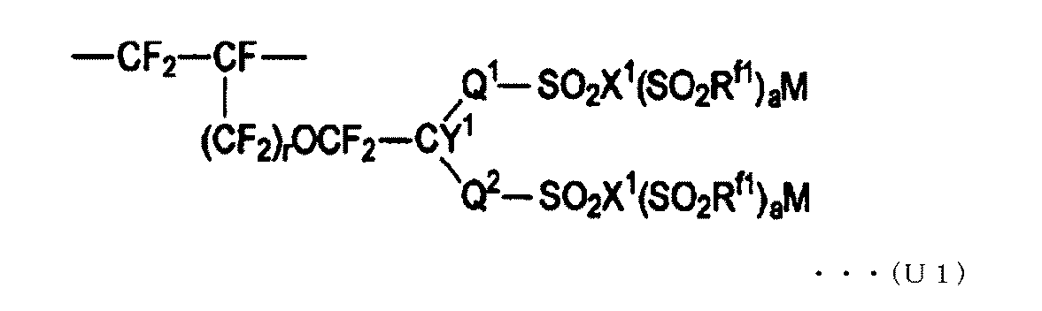
含フッ素ポリマー(S)としては、例えば、層(S’a)及び層(S’b)を構成する共重合体である、スルホン酸型官能基に変換できる基及びフッ素原子を有するモノマー(以下、含フッ素モノマー(S’)とも言う。)と、含フッ素オレフィンとの共重合体(以下、含フッ素ポリマー(S’)とも言う。)中のスルホン酸型官能基に変換できる基を、加水分解処理等によりスルホン酸型官能基に変換した含フッ素ポリマーが好ましい。
含フッ素モノマー(S’)としては、モノマーの製造コスト、他のモノマーとの反応性、得られる含フッ素ポリマーの特性に優れる点から、下式(2)又は下式(3)で表される含フッ素モノマーが好ましい。
CF2=CF-Rf2-A2 ・・・(3)
Rf2は、炭素数1~20のパーフルオロアルキル基であり、エーテル性の酸素原子を含んでいてもよく、直鎖状又は分岐状のいずれでもよい。A2は、スルホン酸型官能基に変換できる基である。具体的には、-SO2F、-SO2Cl、-SO2Br等である。
CF2=CF-O-CF2CF2-SO2F、CF2=CF-O-CF2CF2CF2-SO2F、CF2=CF-O-CF2CF2CF2CF2-SO2F、CF2=CF-O-CF2CF(CF3)-O-CF2CF2-SO2F、CF2=CF-O-CF2CF(CF3)-O-CF2CF2CF2-SO2F、CF2=CF-O-CF2CF(CF3)-SO2F、CF2=CF-CF2CF2-SO2F、CF2=CF-CF2CF2CF2-SO2F、CF2=CF-CF2-O-CF2CF2-SO2F。
含フッ素モノマー(S’)は1種を単独でも、2種以上を組み合わせて用いてもよい。
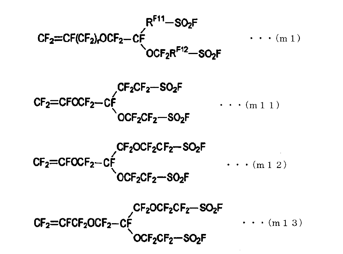
なお、式(m1)で表されるモノマー単位は、式(U1)におけるQ2がOCF2RF12(エーテル性の酸素原子を有していてもよいパーフルオロアルキレン基)であり、Q1がRF11(単結合、又はエーテル性の酸素原子を有していてもよいパーフルオロアルキレン基)であり、SO2X1(SO2Rf1)aMがSO2FもしくはSO2Fを加水分解処理や酸型化処理して得られるスルホン酸型官能基(X1が酸素原子であり、aが0であり、Mが水素、アルカリ金属又は第4級アンモニウム塩基である。)であり、Y1がフッ素原子である構成単位である。
含フッ素ポリマー(S’)のTQ値は、イオン交換膜としての機械的強度及び製膜性の点から、150℃以上が好ましく、170~340℃がより好ましく、170~300℃がさらに好ましい。
乾燥時の層(Sa-1)の厚さは、接着性に寄与する程度の適度な厚さがあればよく、1~55μmが好ましく、1~40μmがより好ましい。
補強材20は、電解質膜10を補強する材料であり、補強布に由来する。補強布は、経糸と緯糸とからなり、経糸と緯糸が直交していることが好ましい。補強布は、補強糸と犠牲糸とからなることが好ましい。
補強糸22としては、パーフルオロカーボンポリマーを含む糸が好ましく、PTFEを含む糸がより好ましく、PTFEのみからなる糸がさらに好ましい。
犠牲糸24としては、PETのみからなるPET糸、PET及びポリブチレンテレフタレート(PBT)の混合物からなるPET/PBT糸、PBTのみからなるPBT糸、又はポリトリメチレンテレフタレート(PTT)のみからなるPTT糸が好ましく、PET糸がより好ましい。
工程(i):カルボン酸型官能基に変換できる基を有する含フッ素ポリマーからなる層(C’)、スルホン酸型官能基に変換できる基を有する含フッ素ポリマーからなる層(S’a)、補強布、及びスルホン酸型官能基に変換できる基を有する含フッ素ポリマーからなる層(S’b)を積層して強化前駆体膜を得て、その後、前記強化前駆体膜をアルカリ性水溶液に接触させて、前記強化前駆体膜中のイオン交換基に変換できる基をイオン交換基に変換する工程。
工程(ii):前記工程(i)を経て得られたイオン交換膜を電解槽に配置し、塩化アルカリ電解の本運転前のコンディショニング運転する工程。
イオン交換膜1は、その最表面の一方又は両方に、無機物粒子層(図示せず)をさらに備えていてもよい。無機物粒子層は、イオン交換膜1の最表面の少なくとも一方に設けられることが好ましく、両方に設けられることがより好ましい。
塩化アルカリ電解により生じるガスがイオン交換膜1の表面に付着すると、塩化アルカリ電解の際に電解電圧が高くなる。無機物粒子層は、塩化アルカリ電解により生じるガスのイオン交換膜1の表面への付着を抑制し、電解電圧の上昇を抑制するために設けられる。無機物粒子層は、無機物粒子と、バインダーとを含む。
本発明の塩化アルカリ電解用イオン交換膜は、前記工程(i)を経て製造されるが、工程(i)は、下記工程(i-a)及び工程(i-b)を有するのが好ましい。
強化前駆体膜は、カルボン酸型官能基に変換できる基を有する含フッ素ポリマーからなる層(C’)、スルホン酸型官能基に変換できる基を有する含フッ素ポリマーからなる層(S’a)、補強布、及びスルホン酸型官能基に変換できる基を有する含フッ素ポリマーからなる層(S’b)を積層して製造できる。すなわち、前駆体膜を積層して強化前駆体膜を製造する際に、補強布とともに積層することにより製造できる。前駆体膜は、イオン交換基に変換できる基を有する含フッ素ポリマーの単層からなる膜であってもよく、複数の層からなる膜であってもよい。
工程(i-a)の一態様においては、まず、カルボン酸型官能基に変換できる基を有する含フッ素ポリマーからなる層(C’)と、スルホン酸型官能基に変換できる基を有する含フッ素ポリマーからなる層(S’a)とを有する積層膜を、共押し出し法によって得る。また、別途、単層押し出し法によってスルホン酸型官能基に変換できる基を有する含フッ素ポリマーからなる層(S’b)からなる膜(以下、膜(S’b)とも言う)を得る。
次いで、膜(S’b)、補強布、及び前記積層膜を、この順に配置し、積層ロール又は真空積層装置を用いてこれらを積層する。この際、前記積層膜は、層(S’a)側が補強布に接するように配置する。このようにして得られた強化前駆体膜は、層(S’b)、補強布、層(S’a)、層(C’)の順に積層されている。
強化前駆体膜における各層の厚さ≒イオン交換膜における乾燥時の各層の厚さ×0.9 ・・・(I)
このため、イオン交換膜中の層(C)、層(Sa)及び層(Sb)の厚さを所望の厚さとするには、強化前駆体膜における対応する層(C’)、層(S’a)及び層(S’b)の厚さを、前記式(I)で求められる厚さとすればよい。
なお、層(Sa)を2層以上とする場合には、別途スルホン酸型官能基に変換できる基を有する含フッ素ポリマーからなる層からなる膜を得て、補強布と前記積層膜の間に層(Sa)が複数の層からなるように積層してもよい。
工程(i-b)においては、前記工程(i-a)で得た強化前駆体膜をアルカリ性水溶液に接触させることによって、該強化前駆体膜のイオン交換基に変換できる基をイオン交換基に変換するとともに、該強化前駆体膜の犠牲糸の少なくとも一部を溶出させることによって、塩化アルカリ電解用イオン交換膜を得る。
イオン交換基の変換は、例えば、日本国特開平1-140987号公報に記載されるような、水溶性有機化合物とアルカリ金属の水酸化物と水との混合物を用いる方法で行われることが好ましい。前記水溶性有機化合物としては、ジメチルスルホキシド、エタノールなどが挙げられる。前記アルカリ金属の水酸化物としては、水酸化カリウム、水酸化ナトリウムが挙げられる。
犠牲糸の溶出は犠牲糸を構成する材料を加水分解することで行われることが好ましい。
本発明の塩化アルカリ電解装置は、本発明の塩化アルカリ電解用イオン交換膜を有する以外は、公知の態様を採用できる。図3は、本発明の塩化アルカリ電解装置の一例を示す模式図である。図3において、塩化アルカリ電解装置100は、陰極112及び陽極114を備える電解槽110と、電解槽110内を陰極112側の陰極室116と、陽極114側の陽極室118とに区切るように電解槽110内に装着されるイオン交換膜1とを有する。
イオン交換膜1は、層(C)12が陰極112側、層(S)14が陽極114側となるように電解槽110内に装着する。
本発明の水酸化アルカリの製造方法は、本発明の塩化アルカリ電解装置によって行われる以外は、公知の態様を採用できる。例えば、塩化ナトリウム水溶液を電解して水酸化ナトリウム水溶液を製造する場合は、塩化アルカリ電解装置100の陽極室118に塩化ナトリウム水溶液を供給し、陰極室116に水酸化ナトリウム水溶液を供給し、陰極室116から排出される水酸化ナトリウム水溶液の濃度を所定の濃度(例えば、32質量%)に保ちながら、塩化ナトリウム水溶液を電解する。
上記の知見を踏まえて、本発明においては、層(Sb)のイオン交換容量や厚さを特定の範囲とし、なおかつ層(C)の厚さや層(Sa)のイオン交換容量や厚さも特定の範囲とすることにより、イオン交換膜の透水量を十分に確保しつつ、生成する水酸化アルカリ水溶液中の塩化アルカリ濃度の上昇を抑制して高い苛性アルカリ品質を維持し、さらに電解電圧を低くできる。
[TQ値の測定]
TQ値は、容量流速:100mm3/秒を示す温度として求めた。容量流速は、島津フローテスターCFD-100D(島津製作所社製)を用い、対象ポリマーを3MPaの加圧下に一定温度のオリフィス(径:1mm、長さ:1mm)から溶融、流出させたときの流出するポリマーの量(mm3/秒)とした。
イオン交換基に変換できる基を有する含フッ素ポリマーの約0.5mgを、そのTQ値より約10℃高い温度にて平板プレスしてフィルムを得た。得られたフィルムを透過型赤外分光分析装置によって分析した。得られたスペクトルのCF2ピーク、CH3ピーク、OHピーク、CFピーク、SO2Fピークの各ピーク高さを用いて、カルボン酸型官能基に変換できる基又はスルホン酸型官能基に変換できる基を有する構成単位の割合を算出した。この割合を加水分解処理後に得られる含フッ素ポリマーにおけるカルボン酸型官能基又はスルホン酸型官能基を有する構成単位の割合とし、イオン交換容量が既知のサンプルを検量線として用いてイオン交換容量を求めた。
なお、上記の測定は、イオン交換基が酸型又はカリウム型もしくはナトリウム型のいずれでも測定が可能である。
イオン交換膜における乾燥時の各層の厚さは、イオン交換膜を90℃で4時間乾燥させたのち、イオン交換膜断面を光学顕微鏡にて観察し、画像ソフト(イノテック社製 Pixs2000 PRO)を用いて求めた。ここで、各層の厚さは、補強材を構成する補強糸及び犠牲糸が存在しない位置における厚さである。
イオン交換膜を、層(C)が陰極に面するように、電解面が縦150mm×横100mmの長方形を有する試験用電解層に配置し、陰極室内の水酸化ナトリウム濃度:32質量%、陽極室内の塩化ナトリウム濃度:200g/L、温度:90℃、電流密度:6kA/m2の条件で塩化ナトリウム水溶液の電解を行い、運転開始から3~10日後の電解電圧(V)、電流効率(%)、生成された水酸化アルカリ水溶液中の塩化ナトリウム濃度を求めた。この際の陰極液への水添加量及び電流効率から、ナトリウムイオン1モル当たりに移動した水のモル量比(モル/モル)として透水量を算出した。
苛性アルカリ品質は、電解で得られた水酸化アルカリ水溶液中の水酸化アルカリに対する塩化アルカリの質量を、指示薬としてクロム酸カリウム水溶液を用い、硝酸銀水溶液を用いた滴定により求め、以下の式により百万分率(単位:ppm)で示した。
(水酸化アルカリ水溶液中の塩化アルカリの質量/水酸化アルカリ水溶液中の水酸化アルカリの質量)×1000000
層(C’)を形成する含フッ素ポリマーとして、TFEと、下式(X)で表される含フッ素モノマーとを共重合して、カルボン酸型官能基に変換できる基を有する含フッ素ポリマー(加水分解後のイオン交換容量:1.08meq/g、以下、ポリマーCと記す。)を合成した。
CF2=CF-O-CF2CF2CF2-COOCH3 ・・・(X)
CF2=CF-O-CF2CF(CF3)-O-CF2CF2-SO2F ・・・(Y)
ポリマーS2を溶融押し出し法により成形し、ポリマーS2からなる層(S’2)(厚さ:30μm)のフィルムBを得た。
PTFEフィルムを急速延伸した後、100デニールの太さにスリットして得たモノフィラメントに2000回/mの撚糸をかけたPTFE糸を補強糸とした。5デニールのPETフィラメントを6本引き揃えた30デニールのマルチフィラメントからなるPET糸を犠牲糸とした。補強糸1本と犠牲糸2本とが交互に配列されるように平織りし、補強布(補強糸の密度:27本/インチ、犠牲糸の密度:108本/インチ)を得た。
フィルムB、補強布、フィルムA、離型用PETフィルム(厚さ:100μm)の順に、かつ、フィルムAの層(C’1)が離型用PETフィルム側となるように重ね、ロールを用いて積層した。離型用PETフィルムを剥がし、強化前駆体膜を得た。強化前駆体膜における各層の厚さは、層(C’)が12μm、層(S’a)が68μm、層(S’b)が30μmであった。
層(S’b)を形成する含フッ素ポリマーとして、ポリマーS2に代えて、TFEと、式(Y)で表される含フッ素モノマーとを共重合して得られた、スルホン酸型官能基に変換できる基を有する含フッ素ポリマー(イオン交換容量:1.4meq/g)を用いた以外は、例1と同様にしてイオン交換膜を得た。なお、強化前駆体膜における各層の厚さは、層(C’)が12μm、層(S’a)が68μm、層(S’b)が30μmであった。
層(S’b)を形成する含フッ素ポリマーとして、ポリマーS2に代えて、TFEと、下式(Z)で表される含フッ素モノマーとを共重合して得られた、スルホン酸型官能基に変換できる基を有する含フッ素ポリマー(イオン交換容量:1.9meq/g)を用いた以外は、例1と同様にしてイオン交換膜を得た。なお、強化前駆体膜における各層の厚さは、層(C’)が12μm、層(S’a)が68μm、層(S’b)が30μmであった。
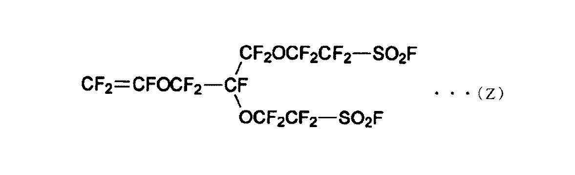
層(S’a)を形成する含フッ素ポリマーとして、ポリマーS1に代えて、TFEと、式(Y)で表される含フッ素モノマーとを共重合して得られた、スルホン酸型官能基に変換できる基を有する含フッ素ポリマー(イオン交換容量:1.25meq/g)を用い、層(S’b)を形成する含フッ素ポリマーとして、ポリマーS2に代えて、TFEと、式(Z)で表される含フッ素モノマーとを共重合して得られた、スルホン酸型官能基に変換できる基を有する含フッ素ポリマー(イオン交換容量:2.2meq/g)を用いた以外は、例1と同様にしてイオン交換膜を得た。なお、強化前駆体膜における各層の厚さは、層(C’)が12μm、層(S’a)が68μm、層(S’b)が30μmであった。
層(S’a)を形成する含フッ素ポリマーとして、ポリマーS1に代えて、TFEと、式(Y)で表される含フッ素モノマーとを共重合して得られた、スルホン酸型官能基に変換できる基を有する含フッ素ポリマー(イオン交換容量:1.0meq/g)を用い、層(S’b)を形成する含フッ素ポリマーとして、ポリマーS2に代えて、TFEと、式(Z)で表される含フッ素モノマーとを共重合して得られた、スルホン酸型官能基に変換できる基を有する含フッ素ポリマー(イオン交換容量:1.9meq/g)を用い、強化前駆体膜における各層の厚さを表1に示すように、層(C’)が20μm、層(S’a)が80μm、層(S’b)が35μmとなるようにした以外は、例1と同様にしてイオン交換膜を得た。
層(S’b)を形成する含フッ素ポリマーとして、ポリマーS2に代えて、TFEと、式(Z)で表される含フッ素モノマーとを共重合して得られた、スルホン酸型官能基に変換できる基を有する含フッ素ポリマー(イオン交換容量:1.9meq/g)を用い、強化前駆体膜における各層の厚さを表1に示すように、層(C’)が12μm、層(S’a)が80μm、層(S’b)が30μmとなるようにした以外は、例1と同様にしてイオン交換膜を得た。
層(S’b)を形成する含フッ素ポリマーとして、ポリマーS2に代えて、TFEと、式(Z)で表される含フッ素モノマーとを共重合して得られた、スルホン酸型官能基に変換できる基を有する含フッ素ポリマー(イオン交換容量:1.9meq/g)を用い、強化前駆体膜における各層の厚さを表1に示すように、層(C’)が12μm、層(S’a)が68μm、層(S’b)が20μmとなるようにした以外は、例1と同様にしてイオン交換膜を得た。
層(S’b)を形成する含フッ素ポリマーとして、ポリマーS2に代えて、TFEと、式(Z)で表される含フッ素モノマーとを共重合して得られた、スルホン酸型官能基に変換できる基を有する含フッ素ポリマー(イオン交換容量:1.9meq/g)を用い、強化前駆体膜における各層の厚さを表1に示すように、層(C’)が12μm、層(S’a)が68μm、層(S’b)が40μmとなるようにした以外は、例1と同様にしてイオン交換膜を得た。
層(S’b)を形成する含フッ素ポリマーとして、ポリマーS2に代えて、TFEと、式(Z)で表される含フッ素モノマーとを共重合して得られた、スルホン酸型官能基に変換できる基を有する含フッ素ポリマー(イオン交換容量:1.9meq/g)を用い、強化前駆体膜における各層の厚さを表1に示すように、層(C’)が12μm、層(S’a)が68μm、層(S’b)が65μmとなるようにした以外は、例1と同様にしてイオン交換膜を得た。
層(S’b)を形成する含フッ素ポリマーとして、ポリマーS2に代えて、TFEと、式(Y)で表される含フッ素モノマーとを共重合して得られた、スルホン酸型官能基に変換できる基を有する含フッ素ポリマー(イオン交換容量:1.1meq/g)を用いた以外は、例1と同様にしてイオン交換膜を得た。なお、強化前駆体膜における各層の厚さは、層(C’)が12μm、層(S’a)が68μm、層(S’b)が30μmであった。
強化前駆体膜における各層の厚さを表1に示すように、層(C’)が7μm、層(S’a)が68μm、層(S’b)が30μmとなるようにした以外は、例10と同様にしてイオン交換膜を得た。
層(C’)を形成する含フッ素ポリマーとして、ポリマーCに代えて、TFEと、式(X)で表される含フッ素モノマーとを共重合して得られた、カルボン酸型官能基に変換できる基を有する含フッ素ポリマー(イオン交換容量:0.95meq/g)を用い、強化前駆体膜を、30質量%のジメチルスルホキシド及び15質量%の水酸化カリウムの水溶液を用いて加水分解した以外は、例11と同様にしてイオン交換膜を得た。なお、強化前駆体膜における各層の厚さは、層(C’)が7μm、層(S’a)が68μm、層(S’b)が30μmであった。
強化前駆体膜における各層の厚さを表1に示すように、層(C’)が35μm、層(S’a)が68μm、層(S’b)が30μmとなるようにした以外は、例2と同様にしてイオン交換膜を得た。
強化前駆体膜における各層の厚さを表1に示すように、層(C’)が12μm、層(S’a)が150μm、層(S’b)が30μmとなるようにした以外は、例3と同様にしてイオン交換膜を得た。
3.0meq/gのイオン交換容量を有する含フッ素ポリマーを、ポリマーS2に代えて層(S’b)を形成する含フッ素ポリマーとして用いるため、TFEと、式(Z)で表される含フッ素モノマーとを共重合することを試みたが、重合に不都合が生じ、フィルムとして成形することができなかった。

一方、例1及び例10では、層(C)が充分な厚さを有することにより、良好な苛性アルカリ品質を有する水酸化ナトリウム水溶液を製造できたが、層(Sb)のイオン交換容量が本発明の条件を満たさず低いため、透水量は低かった。例11及び例12では、層(C)の厚さを薄くすることにより、高い透水量を実現できたが、苛性アルカリ品質に劣る結果となった。例13及び例14では、層(Sb)のイオン交換容量が本発明の条件を満たすため、高い透水量を実現できたが、層(C)の厚さが厚いため(例13)、もしくは層(Sa)の厚さが厚いため(例14)、電解電圧が高かった。例15では、層(Sb)のイオン交換容量が本発明の条件より高いポリマーからなるフィルムの製造を試みたが、フィルムに成形できる共重合体が得られなかった。
Claims (15)
- 陰極側の表面にカルボン酸型官能基を有する含フッ素ポリマーからなる層(C)を有し、陽極側の表面にスルホン酸型官能基を有する含フッ素ポリマーからなる層(S)を有し、前記スルホン酸型官能基を有する含フッ素ポリマーからなる層(S)の中に補強糸を含む補強材が配置され、
前記カルボン酸型官能基を有する層(C)の乾燥時の厚さが9~28μmであり、
前記スルホン酸型官能基を有する含フッ素ポリマーからなる層(S)のうち、
前記補強材よりも陽極側に位置する層(Sb)は、イオン交換容量が1.3~2.5ミリ当量/グラム乾燥樹脂であるスルホン酸型官能基を有する含フッ素ポリマーからなる層を含み、乾燥時の厚さが6~100μmであり、かつ、
前記補強材よりも陰極側に位置する層(Sa)は、イオン交換容量が0.9~1.25ミリ当量/グラム乾燥樹脂であるスルホン酸型官能基を有する含フッ素ポリマーからなる層を含み、乾燥時の厚さが40~110μmであることを特徴とする塩化アルカリ電解用イオン交換膜。 - 前記補強材よりも陽極側に位置する前記スルホン酸型官能基を有する含フッ素ポリマーからなる層(Sb)を構成するスルホン酸型官能基を有する含フッ素ポリマーの少なくとも一部が、下式(U1)で表される構成単位を有するポリマーである、請求項1に記載の塩化アルカリ電解用イオン交換膜。

- 式(U1)で表される構成単位が、式(M1)で表されるモノマーに基づく構成単位である、請求項2に記載の塩化アルカリ電解用イオン交換膜。

フルオロアルキレン基である。] - 前記カルボン酸型官能基を有する含フッ素ポリマーからなる層(C)を構成するカルボン酸型官能基を有する含フッ素ポリマーの少なくとも一部のイオン交換容量が0.5~2.0ミリ当量/グラム乾燥樹脂である請求項1~3のいずれか一項に記載の塩化アルカリ電解用イオン交換膜。
- 前記補強材よりも陰極側に位置する層(Sa)が2層以上からなる層である請求項1~4のいずれか一項に記載の塩化アルカリ電解用イオン交換膜。
- 前記補強材よりも陰極側に位置する層(Sa)を形成する層のうち、最も陰極側に位置する層(Sa-1)の乾燥時の厚さが1~55μmであり、イオン交換容量が0.9~1.25ミリ当量/グラム乾燥樹脂であるスルホン酸型官能基を有する含フッ素ポリマーからなる層である請求項5に記載の塩化アルカリ電解用イオン交換膜。
- 前記補強材が、補強糸と犠牲糸からなる請求項1~6のいずれか一項に記載の塩化アルカリ電解用イオン交換膜。
- さらに少なくとも一方の面の最表面に、無機物粒子層を有する請求項1~7のいずれか一項に記載の塩化アルカリ電解用イオン交換膜。
- カルボン酸型官能基に変換できる基を有する含フッ素ポリマーからなる層(C’)、スルホン酸型官能基に変換できる基を有する含フッ素ポリマーからなる層(S’a)、補強布、及びスルホン酸型官能基に変換できる基を有する含フッ素ポリマーからなる層(S’b)をこの順に積層した強化前駆体膜を得て、その後、前記強化前駆体膜をアルカリ性水溶液に接触させて、前記強化前駆体膜中のイオン交換基に変換できる基をイオン交換基に変換することを特徴とする請求項1~8のいずれか一項に記載の塩化アルカリ電解用イオン交換膜の製造方法。
- 前記補強布が補強糸及び犠牲糸からなり、前記強化前駆体膜をアルカリ水溶液に接触させてイオン交換基に変換できる基をイオン交換基に変換するとともに、前記補強布中の補強糸の少なくとも一部を溶解させて補強材を形成する請求項9に記載の塩化アルカリ電解用イオン交換膜の製造方法。
- 前記アルカリ性水溶液が、水溶性有機化合物とアルカリ金属の水酸化物と水との混合物である請求項9に記載の塩化アルカリ電解用イオン交換膜の製造方法。
- 陰極及び陽極を備える電解槽と、前記電解槽内の前記陰極側の陰極室と前記陽極側の陽極室とを区切る請求項1~8のいずれか一項に記載の塩化アルカリ電解用イオン交換膜とを有することを特徴とする塩化アルカリ電解装置。
- 請求項12に記載の塩化アルカリ電解装置を用いて塩化アルカリを電解することを特徴とする水酸化アルカリの製造方法。
- 陰極室内に酸素を供給しながら塩化アルカリを電解する請求項13に記載の水酸化アルカリの製造方法。
- 請求項13又は14に記載の水酸化アルカリの製造方法であって、生成する水酸化アルカリ水溶液中の水酸化アルカリに対する塩化アルカリの含有量が25ppm以下である水酸化アルカリの製造方法。
Priority Applications (4)
| Application Number | Priority Date | Filing Date | Title |
|---|---|---|---|
| EP17782476.0A EP3444384B1 (en) | 2016-04-13 | 2017-04-13 | Ion exchange membrane for alkali chloride electrolysis, method for its producton and alkali chloride electrolysis apparatus |
| CN201780023588.4A CN109154091B (zh) | 2016-04-13 | 2017-04-13 | 碱金属氯化物电解用离子交换膜、其制造方法及碱金属氯化物电解装置 |
| JP2018512073A JP6954269B2 (ja) | 2016-04-13 | 2017-04-13 | 塩化アルカリ電解用イオン交換膜、その製造方法及び塩化アルカリ電解装置 |
| US16/156,360 US11066751B2 (en) | 2016-04-13 | 2018-10-10 | Ion exchange membrane for alkali chloride electrolysis, method for its production and alkali chloride electrolysis apparatus |
Applications Claiming Priority (2)
| Application Number | Priority Date | Filing Date | Title |
|---|---|---|---|
| JP2016080157 | 2016-04-13 | ||
| JP2016-080157 | 2016-04-13 |
Related Child Applications (1)
| Application Number | Title | Priority Date | Filing Date |
|---|---|---|---|
| US16/156,360 Continuation US11066751B2 (en) | 2016-04-13 | 2018-10-10 | Ion exchange membrane for alkali chloride electrolysis, method for its production and alkali chloride electrolysis apparatus |
Publications (1)
| Publication Number | Publication Date |
|---|---|
| WO2017179663A1 true WO2017179663A1 (ja) | 2017-10-19 |
Family
ID=60042458
Family Applications (2)
| Application Number | Title | Priority Date | Filing Date |
|---|---|---|---|
| PCT/JP2017/015158 Ceased WO2017179664A1 (ja) | 2016-04-13 | 2017-04-13 | 塩化アルカリ電解用イオン交換膜、その製造方法、及び塩化アルカリ電解装置 |
| PCT/JP2017/015157 Ceased WO2017179663A1 (ja) | 2016-04-13 | 2017-04-13 | 塩化アルカリ電解用イオン交換膜、その製造方法及び塩化アルカリ電解装置 |
Family Applications Before (1)
| Application Number | Title | Priority Date | Filing Date |
|---|---|---|---|
| PCT/JP2017/015158 Ceased WO2017179664A1 (ja) | 2016-04-13 | 2017-04-13 | 塩化アルカリ電解用イオン交換膜、その製造方法、及び塩化アルカリ電解装置 |
Country Status (5)
| Country | Link |
|---|---|
| US (2) | US11066751B2 (ja) |
| EP (2) | EP3444385B1 (ja) |
| JP (2) | JP6954269B2 (ja) |
| CN (2) | CN109154091B (ja) |
| WO (2) | WO2017179664A1 (ja) |
Cited By (2)
| Publication number | Priority date | Publication date | Assignee | Title |
|---|---|---|---|---|
| JP2019108542A (ja) * | 2017-12-19 | 2019-07-04 | Agc株式会社 | 塩化アルカリ電解用イオン交換膜、塩化アルカリ電解用イオン交換膜の製造方法および塩化アルカリ電解装置 |
| KR20210124420A (ko) * | 2019-02-14 | 2021-10-14 | 더 케무어스 컴퍼니 에프씨, 엘엘씨 | 다층 양이온 교환 클로르알칼리 막 |
Families Citing this family (5)
| Publication number | Priority date | Publication date | Assignee | Title |
|---|---|---|---|---|
| EP3444385B1 (en) * | 2016-04-13 | 2021-03-03 | Agc Inc. | Ion exchange membrane for alkali chloride electrolysis, production method therefor, and alkali chloride electrolysis device |
| US10865282B2 (en) | 2017-12-18 | 2020-12-15 | Asahi Kasei Kabushiki Kaisha | Ion exchange membrane, method for producing ion exchange membrane, and electrolyzer |
| JP7416047B2 (ja) * | 2019-03-13 | 2024-01-17 | Agc株式会社 | 膜電極接合体 |
| CN110699706B (zh) * | 2019-11-27 | 2021-05-28 | 山东东岳高分子材料有限公司 | 碱金属氯化物电解用含氟离子交换膜 |
| CN113421777B (zh) * | 2021-06-30 | 2023-03-31 | 昆明理工大学 | 一种基于超分子的超宽工作温度范围的水系碱性电解液 |
Citations (9)
| Publication number | Priority date | Publication date | Assignee | Title |
|---|---|---|---|---|
| JPS52124496A (en) * | 1976-04-14 | 1977-10-19 | Japan Storage Battery Co Ltd | Method of electrolyzing alkali metal chloride and apparatus therefor |
| JPS5411098A (en) * | 1977-06-28 | 1979-01-26 | Tokuyama Soda Co Ltd | Electrolyzing method for aqueous solution of alkali metal salt |
| JPH01263288A (ja) * | 1988-04-14 | 1989-10-19 | Asahi Glass Co Ltd | 塩化アルカリの電解方法 |
| JPH0633281A (ja) * | 1992-07-15 | 1994-02-08 | Asahi Glass Co Ltd | 塩化アルカリ水溶液の電解方法 |
| CN103014758A (zh) * | 2012-12-14 | 2013-04-03 | 山东东岳高分子材料有限公司 | 一种超高电流密度条件下运行的离子交换膜及其制备方法 |
| JP2014058707A (ja) * | 2012-09-14 | 2014-04-03 | Asahi Kasei Chemicals Corp | イオン交換膜、イオン交換膜の製造方法及び電解槽 |
| WO2016027862A1 (ja) * | 2014-08-20 | 2016-02-25 | 旭硝子株式会社 | 塩化アルカリ電解用イオン交換膜および塩化アルカリ電解装置 |
| WO2017043592A1 (ja) * | 2015-09-08 | 2017-03-16 | 旭硝子株式会社 | 塩化アルカリ電解用イオン交換膜の製造方法および塩化アルカリ電解装置の製造方法 |
| WO2017043591A1 (ja) * | 2015-09-08 | 2017-03-16 | 旭硝子株式会社 | 塩化アルカリ電解用イオン交換膜の製造方法および塩化アルカリ電解装置の製造方法 |
Family Cites Families (13)
| Publication number | Priority date | Publication date | Assignee | Title |
|---|---|---|---|---|
| JPS61166991A (ja) | 1985-01-18 | 1986-07-28 | Asahi Glass Co Ltd | 食塩電解方法 |
| JP3214571B2 (ja) * | 1991-10-02 | 2001-10-02 | 旭化成株式会社 | フッ素系イオン交換膜 |
| WO2002103083A1 (fr) * | 2001-06-15 | 2002-12-27 | Asahi Glass Company, Limited | Membrane echangeuse de cations contenant de la fluorine et procede par soude electrolytique |
| JP4857560B2 (ja) * | 2002-09-30 | 2012-01-18 | 旭硝子株式会社 | 固体高分子型燃料電池用電解質膜の製造方法 |
| JP5212114B2 (ja) * | 2007-01-31 | 2013-06-19 | 旭硝子株式会社 | 塩化アルカリ電解用イオン交換膜 |
| WO2010095740A1 (ja) * | 2009-02-23 | 2010-08-26 | 旭硝子株式会社 | 陽イオン交換膜およびその製造方法、並びにこれを用いた電解槽 |
| CN103534282B (zh) * | 2011-05-18 | 2016-08-17 | 旭硝子株式会社 | 含氟共聚物及离子交换膜 |
| JP5793444B2 (ja) | 2012-02-13 | 2015-10-14 | 旭化成ケミカルズ株式会社 | 陽イオン交換膜及びこれを用いた電解槽 |
| IN2014DN06873A (ja) * | 2012-02-27 | 2015-05-22 | Asahi Glass Co Ltd | |
| EP3216896B1 (en) * | 2014-11-07 | 2020-06-24 | AGC Inc. | Ion exchange membrane for alkali chloride electrolysis and alkali chloride electrolysis apparatus |
| JP6586961B2 (ja) * | 2014-11-10 | 2019-10-09 | Agc株式会社 | 塩化アルカリ電解用イオン交換膜、製造方法、及び塩化アルカリ電解装置 |
| CN107429411B (zh) * | 2015-04-13 | 2020-09-08 | Agc株式会社 | 电解用离子交换膜的制造方法及电解用离子交换膜 |
| EP3444385B1 (en) * | 2016-04-13 | 2021-03-03 | Agc Inc. | Ion exchange membrane for alkali chloride electrolysis, production method therefor, and alkali chloride electrolysis device |
-
2017
- 2017-04-13 EP EP17782477.8A patent/EP3444385B1/en active Active
- 2017-04-13 EP EP17782476.0A patent/EP3444384B1/en active Active
- 2017-04-13 WO PCT/JP2017/015158 patent/WO2017179664A1/ja not_active Ceased
- 2017-04-13 CN CN201780023588.4A patent/CN109154091B/zh active Active
- 2017-04-13 CN CN201780023566.8A patent/CN109072463B/zh active Active
- 2017-04-13 WO PCT/JP2017/015157 patent/WO2017179663A1/ja not_active Ceased
- 2017-04-13 JP JP2018512073A patent/JP6954269B2/ja active Active
- 2017-04-13 JP JP2018512074A patent/JP6996495B2/ja active Active
-
2018
- 2018-10-10 US US16/156,360 patent/US11066751B2/en active Active
- 2018-10-10 US US16/156,320 patent/US10669641B2/en active Active
Patent Citations (10)
| Publication number | Priority date | Publication date | Assignee | Title |
|---|---|---|---|---|
| JPS52124496A (en) * | 1976-04-14 | 1977-10-19 | Japan Storage Battery Co Ltd | Method of electrolyzing alkali metal chloride and apparatus therefor |
| JPS5411098A (en) * | 1977-06-28 | 1979-01-26 | Tokuyama Soda Co Ltd | Electrolyzing method for aqueous solution of alkali metal salt |
| JPH01263288A (ja) * | 1988-04-14 | 1989-10-19 | Asahi Glass Co Ltd | 塩化アルカリの電解方法 |
| JPH0633281A (ja) * | 1992-07-15 | 1994-02-08 | Asahi Glass Co Ltd | 塩化アルカリ水溶液の電解方法 |
| JP2014058707A (ja) * | 2012-09-14 | 2014-04-03 | Asahi Kasei Chemicals Corp | イオン交換膜、イオン交換膜の製造方法及び電解槽 |
| CN103014758A (zh) * | 2012-12-14 | 2013-04-03 | 山东东岳高分子材料有限公司 | 一种超高电流密度条件下运行的离子交换膜及其制备方法 |
| WO2016027862A1 (ja) * | 2014-08-20 | 2016-02-25 | 旭硝子株式会社 | 塩化アルカリ電解用イオン交換膜および塩化アルカリ電解装置 |
| WO2017043592A1 (ja) * | 2015-09-08 | 2017-03-16 | 旭硝子株式会社 | 塩化アルカリ電解用イオン交換膜の製造方法および塩化アルカリ電解装置の製造方法 |
| WO2017043591A1 (ja) * | 2015-09-08 | 2017-03-16 | 旭硝子株式会社 | 塩化アルカリ電解用イオン交換膜の製造方法および塩化アルカリ電解装置の製造方法 |
| WO2017043590A1 (ja) * | 2015-09-08 | 2017-03-16 | 旭硝子株式会社 | 塩化アルカリ電解用イオン交換膜の製造方法および塩化アルカリ電解装置の製造方法 |
Cited By (3)
| Publication number | Priority date | Publication date | Assignee | Title |
|---|---|---|---|---|
| JP2019108542A (ja) * | 2017-12-19 | 2019-07-04 | Agc株式会社 | 塩化アルカリ電解用イオン交換膜、塩化アルカリ電解用イオン交換膜の製造方法および塩化アルカリ電解装置 |
| KR20210124420A (ko) * | 2019-02-14 | 2021-10-14 | 더 케무어스 컴퍼니 에프씨, 엘엘씨 | 다층 양이온 교환 클로르알칼리 막 |
| KR102873312B1 (ko) * | 2019-02-14 | 2025-10-20 | 더 케무어스 컴퍼니 에프씨, 엘엘씨 | 다층 양이온 교환 클로르알칼리 막 |
Also Published As
| Publication number | Publication date |
|---|---|
| WO2017179664A1 (ja) | 2017-10-19 |
| JPWO2017179663A1 (ja) | 2019-02-21 |
| US20190040537A1 (en) | 2019-02-07 |
| EP3444384B1 (en) | 2021-03-03 |
| CN109154091A (zh) | 2019-01-04 |
| EP3444385B1 (en) | 2021-03-03 |
| CN109072463B (zh) | 2021-02-12 |
| EP3444384A1 (en) | 2019-02-20 |
| EP3444384A4 (en) | 2019-12-25 |
| US10669641B2 (en) | 2020-06-02 |
| JPWO2017179664A1 (ja) | 2019-02-28 |
| JP6954269B2 (ja) | 2021-10-27 |
| JP6996495B2 (ja) | 2022-01-17 |
| US20190040538A1 (en) | 2019-02-07 |
| EP3444385A4 (en) | 2019-12-25 |
| EP3444385A1 (en) | 2019-02-20 |
| CN109154091B (zh) | 2021-10-01 |
| US11066751B2 (en) | 2021-07-20 |
| CN109072463A (zh) | 2018-12-21 |
Similar Documents
| Publication | Publication Date | Title |
|---|---|---|
| WO2017179663A1 (ja) | 塩化アルカリ電解用イオン交換膜、その製造方法及び塩化アルカリ電解装置 | |
| JP6270714B2 (ja) | 強化電解質膜およびその製造方法 | |
| US11447881B2 (en) | Ion exchange membrane for alkali chloride electrolysis and alkali chloride electrolysis apparatus | |
| US10385465B2 (en) | Production method for ion exchange membrane for alkali chloride electrolysis, and production method for alkali chloride electrolysis apparatus | |
| US11020734B2 (en) | Ion exchange membrane for alkali chloride electrolysis, production method, and alkali chloride electrolysis apparatus | |
| US10703872B2 (en) | Production method for ion exchange membrane for alkali chloride electrolysis, and production method for alkali chloride electrolysis apparatus | |
| US10865489B2 (en) | Ion exchange membrane for alkali chloride electrolysis, and alkali chloride electrolysis apparatus | |
| JP2018095663A (ja) | イオン交換膜 | |
| US11434337B2 (en) | Ion exchange membrane for alkali chloride electrolysis, and alkali chloride electrolysis apparatus | |
| WO2017154925A1 (ja) | イオン交換膜、その製造方法および塩化アルカリ電解装置 |
Legal Events
| Date | Code | Title | Description |
|---|---|---|---|
| WWE | Wipo information: entry into national phase |
Ref document number: 2018512073 Country of ref document: JP |
|
| NENP | Non-entry into the national phase |
Ref country code: DE |
|
| WWE | Wipo information: entry into national phase |
Ref document number: 2017782476 Country of ref document: EP |
|
| ENP | Entry into the national phase |
Ref document number: 2017782476 Country of ref document: EP Effective date: 20181113 |
|
| 121 | Ep: the epo has been informed by wipo that ep was designated in this application |
Ref document number: 17782476 Country of ref document: EP Kind code of ref document: A1 |