WO2017179780A1 - 기관튜브 고정용 바이팅블럭 조립체 - Google Patents
기관튜브 고정용 바이팅블럭 조립체 Download PDFInfo
- Publication number
- WO2017179780A1 WO2017179780A1 PCT/KR2016/011237 KR2016011237W WO2017179780A1 WO 2017179780 A1 WO2017179780 A1 WO 2017179780A1 KR 2016011237 W KR2016011237 W KR 2016011237W WO 2017179780 A1 WO2017179780 A1 WO 2017179780A1
- Authority
- WO
- WIPO (PCT)
- Prior art keywords
- tube
- fixing
- support plate
- shaft
- biting
- Prior art date
- Legal status (The legal status is an assumption and is not a legal conclusion. Google has not performed a legal analysis and makes no representation as to the accuracy of the status listed.)
- Ceased
Links
Images



Classifications
-
- A—HUMAN NECESSITIES
- A61—MEDICAL OR VETERINARY SCIENCE; HYGIENE
- A61M—DEVICES FOR INTRODUCING MEDIA INTO, OR ONTO, THE BODY; DEVICES FOR TRANSDUCING BODY MEDIA OR FOR TAKING MEDIA FROM THE BODY; DEVICES FOR PRODUCING OR ENDING SLEEP OR STUPOR
- A61M16/00—Devices for influencing the respiratory system of patients by gas treatment, e.g. ventilators; Tracheal tubes
- A61M16/04—Tracheal tubes
Definitions
- the present invention relates to a biting block assembly, and more particularly, to a biting block assembly that can be easily and stably fixed to the face of the tracheal tube inserted into the patient's mouth.
- Tracheal tubes are intubated into the patient's mouth for resuscitation by ventilators in an intensive care unit or under surgery under general anesthesia, and to secure the airway under the patient's emergency.
- Figure 1 (a) is an exemplary view showing a state in which the tracheal tube 10 is inserted into the patient.
- the tracheal tube 10 has an end balloon 12 inserted into the patient's airway. In this state, the air is supplied to the balloon 12 through the air line 13, and the balloon 12 is expanded to secure an airway.
- the tracheal tube 10 is connected to the connecting tube 17 through the adapter 11, the medical gas supply, anesthesia, oxygen supply, ventilator, etc. are connected through the connecting tube 17.
- the tracheal tube 10 is fixed so as not to fall out by the external force.
- the bandage 20 is wound around the tracheal tube 10 and the bandage 20 is attached to the skin around the mouth.
- the tracheal tube 10 when fixed by the band-aid 20, the tracheal tube 10 is not firmly fixed inside the oral cavity so that the tracheal tube 10 falls out, the patient consciously or unconsciously pull out the tracheal tube 10 by hand. Occasional situations can lead to serious situations. In particular, in the case of children or infants, even a small movement of the tube may cause the tube to fall out of the trachea and an emergency situation may occur, and in addition, a bandage may cause contact dermatitis in patients with weak skin. there was.
- the air line 13 formed around the tracheal tube 10, the connecting pipe 17, the coral respiratory pipe 15, etc. are intricately intertwined and there is a risk that the position may be out of position because they are not fixed to each other. .
- the band-aid 20 is to block the outside of the oral cavity for fixing the tracheal tube 10, there was a disadvantage that it is difficult to insert the suction tube to remove foreign matter inside the oral cavity.
- An object of the present invention is to solve the above-mentioned problem, and to provide a biting block assembly capable of stably fixing a tracheal tube to a patient's face.
- Another object of the present invention is to provide a biting block assembly that can be fixed in a stable position to all of the tubes of various diameters compatible.
- Still another object of the present invention is to provide a biting block assembly capable of supplying oxygen by inserting a tracheal tube so that it does not block the oral cavity and inserting a suction tube.
- the block body in the biting block assembly for fixing the tracheal tube inserted into the patient's oral cavity on the patient's face, is provided with a tube support shaft for protruding a predetermined length to guide the tracheal tube into the oral cavity; ;
- a tooth protection member coupled to a rear surface of the block body and inserted into a mouth of a patient to a predetermined length, and formed of an elastic material and disposed between the teeth of the patient;
- a tube fixing band for fixing a position of the tube support shaft and the tracheal tube;
- Removably coupled to the front of the block body includes a connection tube support member for supporting the tracheal tube.
- the oral support plate may be characterized in that it comprises a support member insert coupled to the connection pipe support member.
- the outer peripheral surface of the tube support shaft may be characterized in that a pair of band fixing shaft is inserted into the tube fixing band.
- the outer peripheral surface of the biting shaft may be characterized in that the biting protrusion is provided to prevent the teeth from sliding.
- the tube fixing band is provided with a length to wrap together the tube support shaft and the tracheal tube located adjacent to the tube support shaft, the tube fixing band is formed through the length along the longitudinal direction of the band
- the fixed shaft may be characterized in that a plurality of fixed shaft insertion hole is formed to be fitted.
- a body fixing tape for fixing the block body to the face of the patient the body fixing tape, the support plate fixing tape is provided to correspond to the shape of the oral support plate and bonded to the oral support plate; It may be characterized in that it comprises a face fixing tape that is formed radially extending from the outer periphery of the support plate fixing tape to be bonded to the face of the patient.
- the oral support plate is provided with a recessed area by the first area and the second area is provided asymmetrically, the second area is provided asymmetrically protrudes than the first area, the support member is inserted
- the part may be provided in the second area so as to protrude on the front surface of the oral support plate.
- the front of the support plate coupling plate may be characterized in that the shock absorbing member in contact with the teeth of the patient is provided.
- the support member insertion portion When the support member insertion portion is fixed to the tube fixing band, it may be characterized in that it is formed at a height that does not interfere with the operation of the tube fixing band.
- an upper part of the recessed area formed in the block body may be provided with an adhesive fixing part for fixing the tracheal tube.
- the biting block assembly according to the present invention may fix the position of the tracheal tube by inserting the block body into the oral cavity of the patient and engaging the tracheal tube with the block body.
- the tube fixing band for coupling the tracheal tube and the block body is a plurality of fixed shaft insertion hole is formed through it can stably fix all the tracheal tube of various diameter diameter.
- biting block assembly of the present invention is formed in the block body so that the suction hole can be inserted into the oral cavity of the patient's mouth, the oxygen supply tube for supplying oxygen into the oral cavity, without directly placing into the oral cavity, into the oral cavity Oxygen can be supplied. This can simplify complicated lines around the mouth and provide stable oxygen supply.
- biting block assembly of the present invention also secures the position of the connection tube connected to the tracheal tube by the connection tube support member once more, so that the fixed state of the tracheal tube can be more firmly maintained.
- biting block assembly of the present invention is manufactured together with the body fixing tape to correspond to the shape of the block body, without attaching a band-aid on the multi-ply tracheal tube and the patient's face, or tie the string behind the patient's head,
- the block body and tracheal tube can be fastened to the patient's face quickly and easily.
- FIG. 1 is an exemplary view showing a state in which a conventional tracheal tube is inserted into the body and fixed to the face of a patient by a band-aid;
- Figure 2 is a perspective view showing an assembled state of the biting block assembly according to the present invention
- Figure 3 is a perspective view showing the configuration of the block body of the biting block assembly according to an embodiment of the present invention
- Figure 4 is a perspective view showing the configuration of the tooth protection member of the biting block assembly of Figure 3,
- FIG. 5 is a perspective view showing the configuration of the connecting tube support member and the tube fixing band of the biting block assembly of Figure 3,
- FIG. 6 is a front view showing the configuration of the body fixing tape of the biting block assembly of FIG.
- FIG. 7 is an exemplary view showing a state in which the tracheal tube is fixed to the face of the patient using the biting block assembly of FIG.
- FIG. 8 is a perspective view showing an assembled state of a biting block assembly according to another embodiment of the present invention.
- FIG. 9 is a perspective view showing the configuration of a block body of the biting block assembly of FIG. 8;
- FIG. 10 is a perspective view illustrating a configuration of a tooth protection member of the biting block assembly of FIG. 8.
- first and second may be used to describe various components, but the components are not limited by the terms. The terms are used only for the purpose of distinguishing one component from another.
- the second component may be referred to as the first component, and similarly, the first component may also be referred to as the second component.
- biting block assembly 100 looks at the biting block assembly 100 according to an embodiment of the present invention.
- FIG. 2 is a perspective view showing a state in which the biting block assembly 100 according to the present invention is assembled.
- the biting block assembly 100 according to the present invention stably fixes the position of the tracheal tube 10 so that the tracheal tube 10 can be inserted into the oral cavity of the patient.
- the biting block assembly 100 includes a block body 110 disposed in the oral cavity of the patient, a tooth protection member 120 coupled to the block body 110 and inserted into the oral cavity of the patient, and the block body 110.
- Removably coupled to the front surface includes a tube support member 130 for supporting the tracheal tube 10, and the tube fixing band 140 for fixing the tracheal tube 10 to the block body (110).
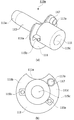
- FIG. 3 (a) is a perspective view showing the configuration of the block body 110
- Figure 3 (b) is a front view showing the front configuration of the block body 110.
- the block body 110 is disposed outside the lips of the patient as shown in Figure 7 to fix the position so that the tracheal tube 10 is inserted into the mouth of the patient.
- the block body 110 is the mouth support plate 111 is disposed in a certain area on the outside of the lips of the patient, and the protective member insertion shaft 113 is coupled to the tooth protection member 120 by protruding a predetermined length to the rear of the oral support plate 111. And a tube support shaft 115 protruding a predetermined length toward the front of the oral support plate 111 to support the tracheal tube 10.
- the oral support plate 111 is formed to be larger than the area of the upper lip and the lower lip in the closed state of the patient so as not to be inserted into the mouth of the patient.
- the oral support plate 111 is formed in a thin plate shape.
- the shape of the oral support plate 111 is provided with a recessed area 111a recessed to a certain depth so that the tracheal tube 10 can be inserted into the oral cavity in a circular shape as shown.
- the recessed region 111a of the oral cavity support plate 111 is formed in a curved shape in contact with the outer diameter of the tube support shaft 115.
- both sides of the oral support plate 111 forming the recessed region (111a) may be provided asymmetrically.
- the recessed region 111a may be formed by the first region 111b and the second region 111c, and the second region 111c may protrude from the first region.
- the support member inserting portion 117 is positioned in the second region 111c to allow the support member inserting portion 117 and the tube support shaft 115 to be spaced apart from each other at a predetermined interval, and the gap is provided on the band fixing shaft 115a.
- Tube fixing band 140 can be easily fixed.
- the protective member insertion shaft 113 is formed to extend a predetermined length toward the rear of the oral support plate 111.
- the protection member insertion shaft 113 is inserted into the biting shaft 123 of the tooth protection member 120 so that the block body 110 and the tooth protection member 120 are coupled to each other.
- the tip 113a of the protective member insertion shaft 113 is formed to have a smaller diameter than other regions so that the insertion member 113 can be easily inserted into the biting shaft 123.
- Tube support shaft 115 is formed to extend a predetermined length vertically out of the oral cavity from the plate surface of the oral support plate 111.
- the tube support shaft 115 is disposed to be external to the recessed area 111a of the oral support plate 111.
- the tube support shaft 115 is fixed to the tracheal tube 10 by the tube fixing band 140. As long as the length of the tube support shaft 115, the tracheal tube 10 may be stably inserted in parallel to the tube support shaft 115 to be stably inserted into the oral cavity.
- a suction insertion hole 115c is formed through the tube support shaft 115.
- the suction insertion hole 115c may be formed in communication with the protection member insertion shaft 113, and may be connected to the tooth protection member 120 to communicate with the biting shaft 123.
- Air can be introduced into the patient's mouth through the suction insertion hole 115c formed in the tube support shaft 115, so that the patient's self-breathing can be enabled, and if there is a foreign object in the patient's mouth, the suction is inserted. Foreign substances can be discharged to the outside.
- a pair of band fixing shafts 115a and 115b protrude from the outer circumferential surface of the tube support shaft 115.
- the band fixing shafts 115a and 115b are inserted into the fixed shaft insertion hole 143 of the tube fixing band 140 as shown in FIG. 7 so that the tube fixing band 140 is connected to the band fixing shafts 115a and 115b.
- the pair of band fixing shaft (115a, 115b) is provided to have an angle of less than 180 degrees from the center of the tube support shaft 115, so that the tube fixing band 140 is fixed to have more than 180 degrees And it is possible to prevent the departure from the band fixing shaft (115a, 115b) by the elastic force of the tube fixing band 140.
- the ends of the band fixing shaft (115a, 115b) is formed in a spherical shape having a larger diameter than the fixed shaft insertion hole 143, the band fixing shaft (115a, 115b) is coupled to the fixed shaft insertion hole (143) To be kept intact.
- Support member insertion portion 117 is formed on the front surface of the oral support plate 111 is coupled to the connection pipe support member 130. In one embodiment, the support member insert 117 is spaced apart from the tube support shaft 115 in the oral support plate 111 by a predetermined interval.
- the protective member insertion shaft 113 and the tube support shaft 115 are disposed coaxially with respect to the oral support plate 111.
- the biting block assembly 100 is disposed in a shape as shown in FIG. That is, the recessed area 111a of the oral support plate 111 is disposed to face the side surface, and the support member inserting portion 117 is disposed at an angle eccentrically under the tube support shaft 115. Since the arrangement position of the support member inserting portion 117 is located below the depression region 111a, when the tracheal tube 10 is guided to the oral cavity through the depression region 111a, the path of the tracheal tube 10 is guided.
- the connection pipe support member 130 is positioned on the top.
- the support member inserting portion 117 is formed with a support member insertion hole 117a is inserted into the coupling end 133 of the connection pipe support member 130.
- the shape of the support member insertion hole 117a may be modified according to the shape of the connection pipe support member 130 to be inserted.
- male and female threads (not shown) may be formed in the support member insertion hole 117a and the coupling end 133 to improve the coupling force.
- 4 is a perspective view showing the configuration of the tooth protection member 120.
- 4 (a) and 4 (b) show the configuration of the tooth protection member 120 at different angles, respectively.
- the block body 110 described above is made of a synthetic resin material is a hard material. Accordingly, the protective member insertion shaft 113 of the block body 110 is inserted into the oral cavity of the patient, and when the patient bites the protective member insertion shaft 113 with the teeth for a long time, damage to the tooth is caused.
- the tooth protection member 120 is formed of a material having elasticity to prevent damage to the tooth and surrounds the outside of the protection member insertion shaft 113. Tooth protection member 120 may be formed of a material such as rubber, silicon.
- the tooth protection member 120 includes a support plate coupling plate 121 in contact with the oral support plate 111, and a biting shaft 123 to which the support plate coupling plate 121 is coupled to a predetermined length.
- the support plate coupling plate 121 is formed to correspond to the shape of the oral support plate 111, and the support plate receiving groove 121a in which the oral support plate 111 is accommodated is formed.
- the biting shaft 123 is formed at the rear end of the support plate accommodation groove 121a. The biting shaft 123 is coupled to the protective member insertion shaft 113.
- the protection member insertion shaft 113 is inserted into the biting shaft 123, and the oral support plate 111 is accommodated in the support plate accommodation groove 121a of the support plate coupling plate 121, so that the block body 110 and the tooth protection member are provided. 120 is coupled.
- a plurality of biting protrusions 123a are formed on the outside of the biting shaft 123 so as to easily bite the patient's teeth.
- An inclined portion 123b may be formed at an end of the biting shaft 123.
- the inclined portion 123b is for easy insertion when the dental protection member 120 is inserted into a patient's mouth.
- the end of the inclined portion 123b may be provided in a round shape in order to prevent a wound on the lips or the mouth of the patient when the inclined portion 123b is inserted.
- the tooth protection member 120 is formed with an air inlet hole 125 communicating the support plate coupling plate 121 and the biting shaft 123.
- the air inlet hole 125 is formed in communication with the suction insertion hole 115c to guide the suction into the oral cavity, or to allow air to flow into the oral cavity.
- connection pipe support member 130 is coupled to the support member insertion portion 117 of the block body 110 as shown in FIG. 7 to support the connection pipe 17 of the tracheal tube 10.
- the connection pipe support member 130 is provided in a semicircular shape at the end of the support shaft 131 having a predetermined length and the support shaft 131, as shown in Figure 5 (a) of the lower portion of the connection pipe 17 It includes a connector support (135) to support.
- the coupling end 133 of the support shaft 131 is fitted into the support member insertion hole 117a of the support member insertion unit 117.
- the support shaft 131 is provided to have a length extending from the oral support plate 110 to the adapter (see 11 in FIG. 1).
- the connector support 135 supports the lower portion of the connector 17 connected to the adapter 11.
- connection pipe 17 is connected to a variety of equipment, such as anesthesia hose, oxygen breathing tube, ventilator.
- the connecting pipe 17 to which oxygen or anesthesia gas is supplied is struck downward by the load.
- the connecting tube 17 is struck downward, the tracheal tube 10 is also struck downward and may be displaced from the oral cavity.
- connection tube support member 130 supports the connection tube 17 so that the tube tube 10 is fixed to the tube support shaft 115 by the tube fixing band 140 to be stably maintained.
- the tube fixing band 140 fixes the tracheal tube 10 to the tube support shaft 115 to fix the position of the tracheal tube 10.
- the tube fixing band 140 is a band body 141 having a predetermined length as shown in (b) of Figure 5, a plurality of fixed shafts formed through the longitudinal direction of the band body 141 Insert hole 143 is included.
- Tube fixing band 140 is bent in a U-shape as shown in Figure 7 and surrounds the tube support shaft 115 and the outside of the tracheal tube (10) together. Then, the band fixing shafts 115a and 115b are inserted into the plurality of fixed shaft insertion holes 143 formed in the tube fixing band 140 to fix the position on the tube support shaft 115.
- the tube 10 of various diameters may be selectively inserted into the band fixing shafts 115a and 115b so that the tube 10 may be closely attached to the tube support shaft 115. do. Thereby it can be used interchangeably with the engine tube 10 of various diameters.
- the band fixing shafts 115a and 115b are provided as a pair, but one side of the tube fixing band 140 through the heterogeneous injection during injection of the block body 110 is the tube support 115. Produced in a fixed form to facilitate the coupling of the tube fixing band 140.
- the tube fixing band 140 is represented by a material having elasticity, but is not limited thereto, and may be provided as a velcro to facilitate fixing and detachment.
- the biting block assembly 100 may further include a body fixing tape 150 for fixing the block body 110 to the face of the patient.
- the band-aid 20 is wound around the entire head as shown in FIG.
- Body fixing tape 150 of the present invention is manufactured to correspond to the shape of the oral support plate 111 of the block body 110 as shown in Figure 6 implemented to be attached to the patient's face faster, cleaner and more stable It was.
- the main body fixing tape 150 is a support plate fixing tape 151 attached to the front of the oral support plate 111, when the oral support plate 111 is disposed in the oral cavity of the patient, as shown in (b) of FIG. It includes a face fixing tape 153 is extended to a predetermined length to the outer periphery of the support plate fixing tape 151 attached to the face of the patient.
- the support plate fixing tape 151 is formed in a size corresponding to the shape of the oral support plate 111, the support shaft exposure hole 151a for exposing the tube support shaft 115 to the outside, and a pair of band fixing shafts 115a.
- the fixed shaft exposure hole 151b for exposing the 115b to the outside and the insertion shaft exposure hole 152 for exposing the support member inserting portion 117 to the outside are formed therethrough.
- Face fixing tape 153 is fixed to the face is formed by extending a predetermined length in the face direction at regular intervals on the outer periphery of the support plate fixing tape 151.
- the tooth protection member 120 is coupled to the block body 110.
- the protective member insertion shaft 113 is inserted into the biting shaft 123, and the oral support plate 111 is fitted into the support plate accommodation groove 121a.
- the biting shaft 123 is inserted into the oral cavity of the patient, and the tooth of the patient bites the biting shaft 123. Then, the connection pipe support member 130 is coupled to the support member insertion portion 117.
- the operator attaches the body fixing tape 150 to the front surface of the oral support plate 111 and attaches the plurality of face fixing tapes 153 to the face of the patient.
- the tracheal tube 10 is inserted into the oral cavity M of the patient as shown in FIG. 7.
- the tracheal tube 10 is inserted into the oral cavity M of the patient through the recessed region 111a, and the tracheal tube 10 is positioned side by side on the sidewall of the tube support shaft 115.
- the operator is bending the tube fixing band 140 in a U-shape to surround the outside of the tracheal tube 10 and the tube support shaft 115, the fixed shaft insertion hole 143 of both ends of the tube fixing band 140 Insert the band fixing shaft (115a, 115b) protruding from the tube support shaft (115).
- the tracheal tube 10 and the tube support shaft 115 are fixed by the tube fixing band 140.
- the connector tube 17 extending from the tube tube 10 is seated on the connector tube support 135 of the connector tube support member 130 so that the tube tube 10 is not bent downward by the load and is perpendicular to the oral cavity. So that it can be positioned stably.
- biting block assembly (100a) according to another embodiment of the present invention.
- biting block assembly 100 according to an embodiment of the present invention.
- the same as described in the biting block assembly 100 according to an embodiment of the present invention will be omitted.
- FIG. 8 is a perspective view showing an assembled state of a biting block assembly according to another embodiment of the present invention
- Figure 9 is a perspective view showing the configuration of the block body of the biting block assembly according to another embodiment of the present invention
- 3A is a perspective view showing the structure of the block body 110a
- FIG. 3B is a front view showing the front structure of the block body 110a.
- 10 is a perspective view showing the configuration of the tooth protection member of the biting block assembly according to another embodiment
- Figure 10 (a) and Figure 10 (b) is a configuration of the tooth protection member 120a at different angles, respectively Shown.
- Biting block assembly (100a) according to another embodiment of the present invention is the same as the above-mentioned embodiment the tooth protection member (120a) is connected to the block body (110a), and then by the tube fixing band 140 After fixing the tube 10 to the tube support shaft 115 has a configuration to support the tube tube 10 by coupling the connection tube support member 130 to the block body (110a).
- Block body (110a) shown in Figure 9 is a mouth support plate 111 is disposed in a certain area on the outside of the lips of the patient, and a protective member insertion is projected a predetermined length to the rear of the oral support plate 111 is coupled to the tooth protection member (120a).
- the shaft 113 and the tube support shaft 115 protruding a predetermined length toward the front of the oral support plate 111 to support the tracheal tube 10 in contact.
- a depression region 111a is formed in the oral cavity support plate 111, and a support member inserting portion 117 is provided in one region of the oral cavity support plate 111 forming the depression region 111a.
- the support member inserting portion 117 may be formed at a height that does not interfere with the operation of the tube fixing band 140 when the tube fixing band 140 is fixed to the tube support shaft 115.
- the oral support plate 111 is asymmetrically provided, and the supporting member inserting portion 117 is provided in the protruding region 111a of the asymmetrical region. There was a predetermined interval between the tube support shaft 115 and the support member insert 117, there was a space for fixing the tube fixing band 140.
- the support member insertion part 117 shown in FIG. 9 is provided on the surface of the oral support plate 111 in which the recessed area 111a is formed symmetrically, and the separation distance from the tube support shaft 115 is narrowed. At this time, in order to facilitate the coupling of the tube fixing band 140, by lowering the height of the support member inserting portion 117 can secure a space for fixing the tube fixing band 140.
- the shape of the support member inserting portion 117 is represented as a protrusion structure, but is not limited thereto, and may be formed as a groove structure recessed in the oral cavity support plate 111.
- a shock absorbing member 127 may be provided on the front surface of the tooth protection member 120a illustrated in FIG. 10.
- the shock absorbing member 127 is formed of a softer material than the material of the tooth protection member 120 in order to prevent the tooth from being damaged. It may be attached to the front of the support plate coupling plate 121.
- the shock absorbing member 127 may be provided in a curved strip shape on the support plate coupling plate 121 outside the biting shaft 123.
- biting block assembly 100a has an upper portion of the recessed area 111a formed in the convex body 110a when the block body 110a and the tooth protection member 120a are coupled to each other.
- Adhesion fixing part 160 may be provided.
- Adhesion fixing unit 160 may prevent the separation of the tracheal tube at the time of fixing using the tube fixing band 140 by first fixing the tracheal tube 10 to prevent this.
- the adhesive fixing unit 160 may be provided with a double-sided tape, it may be fixed so as to span both sides of the block body (110a) and the tooth protection member (120a) in the upper portion of the recessed region (111a).
- the tracheal tube 10 may be seated by removing the tape on the adhesion fixing unit 160.
- 10 tracheal tube, 11: adapter, 12: balloon, 13: air line, 15: oxygen breathing tube, 17: connector, 20: band-aid, 100, 100a: biting block assembly, 110, 110a: block body, 111: Oral support plate, 111a: recessed area, 111b: first area, 111c: second area, 113: protective member insertion axis, 113a: tip, 115: tube support axis, 115a, 115b: band fixing shaft, 115c: suction insertion hole , 117: support member insertion shaft, 117a: support member insertion hole, 120, 120a: tooth protection member, 121: support plate coupling plate, 121a: support plate receiving groove, 123: biting shaft, 123a: biting protrusion, 123b: inclined portion, 125: air inlet hole, 127: shock absorbing member, 130: connection tube support member, 131: support shaft, 133: coupling end, 135: connection tube support, 140: tube fixing band, 100
Landscapes
- Health & Medical Sciences (AREA)
- Pulmonology (AREA)
- Emergency Medicine (AREA)
- Engineering & Computer Science (AREA)
- Anesthesiology (AREA)
- Biomedical Technology (AREA)
- Heart & Thoracic Surgery (AREA)
- Hematology (AREA)
- Life Sciences & Earth Sciences (AREA)
- Animal Behavior & Ethology (AREA)
- General Health & Medical Sciences (AREA)
- Public Health (AREA)
- Veterinary Medicine (AREA)
- Media Introduction/Drainage Providing Device (AREA)
Abstract
본 발명은 환자의 구강 내에 삽입되는 기관튜브를 환자의 안면에 고정시키는 바이팅블럭 조립체에 있어서, 일정 길이 돌출되어 기관튜브를 구강 내부로 안내하는 튜브지지축이 구비되는 블록본체와 상기 블록본체의 후면에 결합되어 환자의 구강 내부로 일정 길이 삽입되며, 탄성을 갖는 소재로 형성되어 환자의 치아 사이에 배치되는 치아보호부재와 상기 튜브지지축과 상기 기관튜브의 위치를 고정시키는 튜브고정밴드와 상기 블록본체의 전면에 착탈가능하게 결합되어 기관튜브를 접촉지지하는 연결관지지부재를 포함하는 것을 특징으로 하는 바이팅블럭 조립체를 제공한다.
Description
본 발명은 바이팅블럭 조립체에 관한 것으로서, 보다 자세히는 환자의 구강내부로 삽입되는 기관튜브를 환자의 안면에 안정적으로 간편하게 고정할 수 있는 바이팅블럭 조립체에 관한 것이다.
기관튜브는 전신마취 하에 시행되는 수술이나 중환자실에서 인공 호흡기에 의한 인공호흡을 위해, 그리고 환자의 응급상황 하에 기도확보를 위해 환자의 구강내부로 삽관된다.
도 1의 (a)는 환자에게 기관튜브(10)가 삽입된 상태를 도시한 예시도이다. 도시된 바와 같이 기관튜브(10)는 단부의 벌룬(12)이 환자의 기도 내부로 삽입된다. 이 상태에서 에어라인(13)을 통해 벌룬(12)으로 공기를 공급하여 벌룬(12)이 확장되며 기도를 확보하게 된다. 기관튜브(10)는 어댑터(11)를 통해 연결관(17)이 연결되고, 연결관(17)을 통해 의료용 가스 공급기, 마취기, 산소공급기, 인공호흡기 등이 연결된다.
그런데, 기관튜브(10)를 기관 내에 적당한 길이로 삽관한 다음에는 기관튜브(10)가 외력에 의해 빠지지 않도록 고정시키게 된다. 이를 위해 도 1의 (b)에 도시된 바와 같이 기관튜브(10) 주위를 반창고(20)로 감고 입 주위 피부에 반창고(20)를 붙이게 된다.
그런데, 이렇게 반창고(20)로 고정할 경우 기관튜브(10)가 구강 내부에 단단히 고정이 안되어 기관튜브(10)가 외부로 빠지게 되며, 환자가 의식적으로나 무의식적으로 기관튜브(10)를 손으로 빼는 경우가 생겨 심각한 상황을 초래할 수 있다. 특히, 소아나 영유아의 경우 튜브의 조그만 이동에 의해서도 튜브가 기관 밖으로 빠져 응급상황이 발생하는 경우도 있을 수 있으며, 또한 반창고를 붙임으로써 피부가 약한 환자의 경우 접촉성 피부염을 유발시킬 수 있는 문제점이 있었다.
또한, 기관튜브(10) 주변으로 형성된 에어라인(13)과, 연결관(17), 산호호흡관(15) 등이 복잡하게 얽혀 있고 서로 위치가 고정이 되지 않아 위치가 벗어날 수 있는 위험이 있었다.
또한, 반창고(20)가 기관튜브(10) 고정을 위해 구강 외부를 막게 되어 구강 내부의 이물질 제거를 위해 석션관을 삽입하기 어려운 단점이 있었다.
본 발명의 목적은 상술한 문제를 해결하기 위한 것으로, 안정적으로 기관튜브를 환자의 안면에 고정할 수 있는 바이팅블럭 조립체를 제공하는 것이다.
본 발명의 다른 목적은 다양한 직경의 기관튜브를 호환하여 모두 안정적으로 위치를 고정할 수 있는 바이팅블럭 조립체를 제공하는 것이다.
본 발명의 또 다른 목적은 기관튜브를 삽입하더도 구강을 막지 않아 산소공급이 가능하며, 석션관을 삽입할 수 있는 바이팅블럭 조립체를 제공하는 것이다.
본 발명이 해결하고자 하는 과제는 이상에서 언급된 과제에 국한되지 않으며 여기서 언급되지 않은 또 다른 과제들은 아래의 기재로부터 당업자에게 명확하게 이해될 수 있을 것이다.
본 발명의 실시예는, 환자의 구강 내에 삽입되는 기관튜브를 환자의 안면에 고정시키는 바이팅블럭 조립체에 있어서, 일정 길이 돌출되어 기관튜브를 구강 내부로 안내하는 튜브지지축이 구비되는 블록본체와; 상기 블록본체의 후면에 결합되어 환자의 구강 내부로 일정 길이 삽입되며, 탄성을 갖는 소재로 형성되어 환자의 치아 사이에 배치되는 치아보호부재와; 상기 튜브지지축과 상기 기관튜브의 위치를 고정시키는 튜브고정밴드와; 상기 블록본체의 전면에 착탈가능하게 결합되어 기관튜브를 접촉지지하는 연결관지지부재를 포함한다.
상기 블록본체는, 입술의 외부에 접촉배치되는 판상의 구강지지판과; 상기 구강지지판의 후방으로 일정 길이 연장되어 상기 치아보호부재와 결합되는 보호부재삽입축과; 상기 구강지지판에서 상기 연결관지지부재와 결합되는 지지부재삽입부를 포함하는 것을 특징으로 할 수 있다.
바람직하게는, 상기 튜브지지축의 외주면에는 상기 튜브고정밴드에 삽입되는 한 쌍의 밴드고정축이 구비되는 것을 특징으로 할 수 있다.
바람직하게는, 상기 치아보호부재는, 상기 구강지지판을 내부에 수용하여 상기 구강지지판과 결합되는 지지판결합판과, 지지판결합판으로부터 구강 내부로 일정 길이 삽입되며, 상기 보호부재삽입축에 결합되는 바이팅축을 포함하되, 상기 바이팅축의 외주면에는 치아가 미끄러지는 것을 방지하는 바이팅돌기가 구비되는 것을 특징으로 할 수 있다.
바람직하게는, 상기 튜브고정밴드는 상기 튜브지지축과, 상기 튜브지지축에 인접하게 위치된 기관튜브를 함께 감쌀 수 있는 길이로 구비되며, 상기 튜브고정밴드에는 길이방향을 따라 관통형성되어 상기 밴드고정축이 끼움결합되는 복수개의 고정축삽입공이 형성되는 것을 특징으로 할 수 있다.
바람직하게는, 상기 블록본체를 환자의 안면에 고정하는 본체고정테이프를 더 포함하며, 상기 본체고정테이프는, 상기 구강지지판의 형상에 대응되게 구비되어 상기 구강지지판에 접착되는 지지판고정테이프와; 상기 지지판고정테이프의 외주연으로부터 방사상으로 일정 길이 연장형성되어 환자의 안면에 접착되는 안면고정테이프를 포함하는 것을 특징으로 할 수 있다.
바람직하게는, 상기 구강지지판은 비대칭으로 마련되는 제1 영역과 제2 영역에 의해 함몰영역이 구비되며, 비대칭으로 마련되는 상기 제2 영역은 상기 제1 영역보다 돌출되도록 마련되며, 상기 지지부재삽입부는 상기 구강지지판의 전면에 돌출되도록 상기 제2 영역에 구비되는 것을 특징으로 할 수 있다.
상기 지지판결합판의 전면에는 환자의 치아와 접촉하는 충격흡수부재가 구비되는 것을 특징으로 할 수 있다.
상기 지지부재삽입부는 튜브고정밴드가 고정되는 경우, 상기 튜브고정밴드의 동작을 방해하지 않는 높이로 형성되는 것을 특징으로 할 수 있다.
상기 블록본체와 상기 치아보호부재가 결합시, 상기 블록본체에 형성되는 함몰영역의 상부에는 기관튜브를 고정하는 접착고정부가 구비되는 것을 특징으로 할 수 있다.
실시예에 따르면, 본 발명에 따른 바이팅블럭 조립체는 블럭본체를 환자의 구강에 삽입시키고 기관튜브를 블럭본체에 결합하여 기관튜브의 위치를 고정할 수 있다.
이때, 기관튜브와 블럭본체를 결합시키는 튜브고정밴드는 복수개의 고정축삽입공이 관통형성되어 다양한 직경의 직경의 기관튜브를 모두 안정적으로 고정할 수 있다.
또한, 본 발명의 바이팅블럭 조립체는 블럭본체에 환자의 구강으로 산소와 석션을 삽입할 수 있는 석션삽입공이 형성되므로, 구강내로 산소를 공급하는 산소공급관을 구강내로 직접 배치하지 않고, 구강내부로 산소를 공급할 수 있다. 이에 의해 구강 주변의 복잡한 라인들을 간소화할 수 있고 산소를 안정적으로 공급할 수 있다.
또한, 석션삽입공을 통해 석션을 삽입할 수 있으므로, 환자의 구강내부의 이물질을 외부로 용이하게 배출할 수 있다.
뿐만 아니라, 본 발명의 바이팅블럭 조립체는 연결관지지부재에 의해 기관튜브에 연결된 연결관의 위치도 한번 더 고정시켜 주므로 기관튜브의 고정상태를 보다 더 견고하게 유지할 수 있다.
또한, 본 발명의 바이팅블럭 조립체는 블럭본체의 형상에 대응되게 본체고정테이프가 함께 제조되므로, 반창고를 여러겹 기관튜브와 환자의 얼굴에 부착하거나, 끈을 환자의 머리뒤에서 묶는 번거로운 작업 없이, 빠르고 간편하게 블럭본체와 기관튜브를 환자의 안면에 고정시킬 수 있다.
본 발명의 다양하면서도 유익한 장점과 효과는 상술한 내용에 한정되지 않으며, 본 발명의 구체적인 실시형태를 설명하는 과정에서 보다 쉽게 이해될 수 있을 것이다.
도 1은 종래 기관튜브가 신체에 삽입된 상태와, 반창고에 의해 환자의 안면에 고정된 상태를 도시한 예시도,
도 2는 본 발명에 따른 바이팅블럭 조립체의 조립된 상태를 도시한 사시도,
도 3은 본 발명의 일실시예에 따른 바이팅블럭 조립체의 블럭본체의 구성을 도시한 사시도,
도 4는 도 3의 바이팅블럭 조립체의 치아보호부재의 구성을 도시한 사시도,
도 5는 도 3의 바이팅블럭 조립체의 연결관지지부재와 튜브고정밴드의 구성을 도시한 사시도,
도 6은 도 3의 바이팅블럭 조립체의 본체고정테이프의 구성을 도시한 정면도,
도 7은 도 3의 바이팅블럭 조립체를 이용해 환자의 안면에 기관튜브를 고정한 상태를 도시한 예시도이고,
도 8은 본 발명의 또 다른 실시예에 따른 바이팅블럭 조립체의 조립된 상태를 도시한 사시도,
도 9는 도 8의 바이팅블럭 조립체의 블럭본체의 구성을 도시한 사시도,
도 10은 도 8의 바이팅블럭 조립체의 치아보호부재의 구성을 도시한 사시도이다.
본 발명은 다양한 변경을 가할 수 있고 여러 가지 실시 예를 가질 수 있는 바, 특정 실시 예를 도면에 예시하고 설명하고자 한다. 그러나, 이는 본 발명 실시 예를 특정한 실시 형태에 대해 한정하려는 것이 아니며, 실시 예의 사상 및 기술 범위에 포함되는 모든 변경, 균등물 내지 대체물을 포함하는 것으로 이해되어야 한다.
제 1, 제 2 등과 같이 서수를 포함하는 용어는 다양한 구성 요소들을 설명하는데 사용될 수 있지만, 상기 구성 요소들은 상기 용어들에 의해 한정되지는 않는다. 상기 용어들은 하나의 구성 요소를 다른 구성 요소로부터 구별하는 목적으로만 사용된다. 예를 들어, 실시 예의 권리 범위를 벗어나지 않으면서 제 2 구성 요소는 제 1 구성 요소로 명명될 수 있고, 유사하게 제 1 구성 요소도 제 2 구성 요소로 명명될 수 있다. 및/또는 이라는 용어는 복수의 관련된 기재된 항목들의 조합 또는 복수의 관련된 기재된 항목들 중의 어느 항목을 포함한다.
본 출원에서 사용한 용어는 단지 특정한 실시 예를 설명하기 위해 사용된 것으로, 본 발명 실시 예를 한정하려는 의도가 아니다. 단수의 표현은 문맥상 명백하게 다르게 뜻하지 않는 한, 복수의 표현을 포함한다. 본 출원에서, "포함하다" 또는 "가지다" 등의 용어는 명세서상에 기재된 특징, 숫자, 단계, 동작, 구성 요소, 부품 또는 이들을 조합한 것이 존재함을 지정하려는 것이지, 하나 또는 그 이상의 다른 특징들이나 숫자, 단계, 동작, 구성 요소, 부품 또는 이들을 조합한 것들의 존재 또는 부가 가능성을 미리 배제하지 않는 것으로 이해되어야 한다.
실시 예의 설명에 있어서, 어느 한 element가 다른 element의 "상(위) 또는 하(아래)(on or under)"에 형성되는 것으로 기재되는 경우에 있어, 상(위) 또는 하(아래)(on or under)는 두 개의 element가 서로 직접(directly)접촉되거나 하나 이상의 다른 element가 상기 두 element 사이에 배치되어(indirectly) 형성되는 것을 모두 포함한다. 또한 "상(위) 또는 하(아래)(on or under)"으로 표현되는 경우 하나의 element를 기준으로 위쪽 방향뿐만 아니라 아래쪽 방향의 의미도 포함할 수 있다.
이하, 첨부된 도면을 참조하여 실시 예를 상세히 설명하되, 도면 부호에 관계없이 동일하거나 대응하는 구성 요소는 동일한 참조 번호를 부여하고 이에 대한 중복되는 설명은 생략하기로 한다.
도 1 내지 도 7는, 본 발명을 개념적으로 명확히 이해하기 위하여, 주요 특징 부분만을 명확히 도시한 것이며, 그 결과 도해의 다양한 변형이 예상되며, 도면에 도시된 특정 형상에 의해 본 발명의 범위가 제한될 필요는 없다.
이들 도면을 참조하여 살펴보면, 본 발명의 일 실시예에 따른 바이팅블럭 조립체(100)를 살펴본다.
도 2는 본 발명에 따른 바이팅블럭 조립체(100)가 조립된 상태를 도시한 사시도이다. 본 발명에 따른 바이팅블럭 조립체(100)는 환자의 구강내부로 기관튜브(10)가 삽입될 수 있도록 기관튜브(10)의 위치를 안정적으로 고정한다.
바이팅블럭 조립체(100)는 환자의 구강에 배치되는 블럭본체(110)와, 블럭본체(110)에 결합되어 환자의 구강내부로 삽입되는 치아보호부재(120)와, 블럭본체(110)의 전면에 착탈가능하게 결합되어 기관튜브(10)를 지지하는 연결관지지부재(130)와, 블럭본체(110)에 기관튜브(10)를 고정시키는 튜브고정밴드(140)를 포함한다.
도 3의 (a)는 블럭본체(110)의 구성을 도시한 사시도이고, 도 3의 (b)는 블럭본체(110)의 정면구성을 도시한 정면도이다. 블럭본체(110)는 도 7에 도시된 바와 같이 환자의 입술 외측에 배치되어 기관튜브(10)가 환자의 구강으로 삽입되도록 위치를 고정한다.
블럭본체(110)는 환자의 입술 외측에 일정 면적 배치되는 구강지지판(111)과, 구강지지판(111)의 후방으로 일정길이 돌출되어 치아보호부재(120)와 결합되는 보호부재삽입축(113)과, 구강지지판(111)의 전방으로 일정길이 돌출되어 기관튜브(10)를 접촉지지하는 튜브지지축(115)을 포함한다.
구강지지판(111)은 환자가 입을 다문 상태에서 윗입술과 아랫입술의 면적보다 크게 구비되어 환자의 구강 내부로 삽입되지 않게 형성된다. 구강지지판(111)은 얇은 판상 형태로 형성된다. 구강지지판(111)의 형상은 도시된 바와 같이 원형의 형태에서 기관튜브(10)가 구강 내부로 삽입될 수 있도록 일정깊이 함몰된 함몰영역(111a)이 구비된다.
이 때, 구강지지판(111)의 함몰영역(111a)은 튜브지지축(115)의 외경과 접하게 곡면형태로 형성된다. 이에 의해 기관튜브(10)가 구강(M) 내부로 삽입될 때, 기관튜브(10)의 일측이 튜브지지축(115)과 접촉지지될 수 있다.
일실시예로, 함몰영역(111a)을 형성하는 구강지지판(111)의 양측은 서로 비대칭으로 마련될 수 있다. 함몰영역(111a)은 제1 영역(111b)과 제2 영역(111c)에 의해 형성되며, 제2 영역(111c)은 제1 영역에 비해 돌출되도록 마련될 수 있다. 제2 영역(111c)에는 지지부재삽입부(117)가 위치하여 지지부재삽입부(117)와 튜브지지축(115)이 일정간격 이격되도록 할 수 있으며, 이 간격은 밴드고정축(115a)에 튜브고정밴드(140)를 쉽게 고정할 수 있도록 한다.
보호부재삽입축(113)은 구강지지판(111)의 후방으로 일정 길이 연장형성된다. 보호부재삽입축(113)은 치아보호부재(120)의 바이팅축(123) 내부로 삽입되어 블럭본체(110)와 치아보호부재(120)가 결합되도록 한다. 보호부재삽입축(113)의 선단(113a)는 타영역에 비해 직경이 작게 형성되어 바이팅축(123) 내부로의 삽입이 보다 용이하도록 한다.
튜브지지축(115)은 구강지지판(111)의 판면에서 구강외부로 수직하게 일정길이 연장되게 형성된다. 튜브지지축(115)은 구강지지판(111)의 함몰영역(111a)과 외접하게 배치된다. 튜브지지축(115)은 튜브고정밴드(140)에 의해 기관튜브(10)와 고정된다. 튜브지지축(115)의 길이만큼 기관튜브(10)는 튜브지지축(115)에 나란하게 위치가 고정되어 구강 내부로 안정적으로 삽입될 수 있다.
한편, 튜브지지축(115)에는 석션삽입공(115c)이 관통형성된다. 석션삽입공(115c)은 보호부재삽입축(113)에 연통되게 형성되고, 치아보호부재(120)와 연결되어 바이팅축(123)과도 연통될 수 있다.
튜브지지축(115)에 형성된 석션삽입공(115c)을 통해 환자의 구강 내부로 공기가 유입될 수 있어 환자의 자가호흡이 가능해질 수 있고, 환자의 구강내부에 이물질이 있는 경우 석션을 삽입하여 이물질을 외부로 배출할 수 있다.
여기서, 튜브지지축(115)의 외주면에는 한 쌍의 밴드고정축(115a,115b)이 돌출형성된다. 밴드고정축(115a,115b)은 도 7에 도시된 바와 같이 튜브고정밴드(140)의 고정축삽입공(143)에 삽입되어 튜브고정밴드(140)가 밴드고정축(115a,115b)과 기관튜브(10)를 고정하도록 한다. 일실시예로, 한 쌍의 밴드고정축(115a,115b)은 튜브지지축(115)의 중심으로부터 180도 이하의 각을 가지도록 마련되어, 튜브고정밴드(140)가 180도 이상의 가지도록 고정되도록 하며 튜브고정밴드(140)의 자체 탄성력에 의해 밴드고정축(115a,115b)으로부터 이탈을 방지할 수 있다.
또한, 밴드고정축(115a,115b)의 단부는 고정축삽입공(143)에 비해 큰 직경을 갖는 구 형태로 형성되어, 밴드고정축(115a,115b)이 고정축삽입공(143)에 결합된 상태가 유지되도록 한다.
지지부재삽입부(117)는 구강지지판(111)의 전면에 형성되어 연결관지지부재(130)와 결합된다. 일실시예로, 지지부재삽입부(117)는 구강지지판(111)에서 튜브지지축(115)으로부터 일정 간격 이격되게 배치된다.
보호부재삽입축(113)과 튜브지지축(115)은 구강지지판(111)을 중심으로 동축상에 배치된다. 바이팅블럭 조립체(100)가 환자의 구강에 배치될 때 도 3의 (b)에 도시된 바와 같은 형태로 배치된다. 즉, 구강지지판(111)의 함몰영역(111a)이 측면을 향하게 배치되고, 지지부재삽입부(117)는 튜브지지축(115)의 하부에서 일정 각도 편심되게 배치된다. 이러한 지지부재삽입부(117)의 배치위치는 함몰영역(111a)의 하부에 위치하게 되므로, 함몰영역(111a)을 통해 기관튜브(10)가 구강으로 안내될 때, 기관튜브(10)의 경로상에 연결관지지부재(130)가 위치하게 된다.
지지부재삽입부(117)에는 지지부재삽입공(117a)이 형성되어 연결관지지부재(130)의 결합단(133)이 삽입된다. 지지부재삽입공(117a)의 형상은 삽입되는 연결관지지부재(130)의 형상에 따라 변형실시될 수 있다. 또한, 결합력을 향상시키기 위해 지지부재삽입공(117a)과 결합단(133)에는 암수 나사산(미도시)이 형성될 수 있다.
도 4는 치아보호부재(120)의 구성을 도시한 사시도이다. 도 4의 (a)와 도 4의 (b)는 서로 다른 각도에서 치아보호부재(120)의 구성을 각각 도시하였다.
앞서 설명한 블럭본체(110)는 합성수지 재질로 형성되므로 경질재질이다. 이에 따라 블럭본체(110)의 보호부재삽입축(113)이 환자의 구강내부로 삽입되고, 환자가 치아로 보호부재삽입축(113)을 장기간 물고 있게 되면 치아에 손상이 오게 된다.
치아보호부재(120)는 치아의 손상을 방지하기 위해 탄성을 갖는 소재로 형성되어 보호부재삽입축(113)의 외부를 감싼다. 치아보호부재(120)는 고무, 실리콘 등의 재질로 형성될 수 있다. 치아보호부재(120)는 구강지지판(111)과 접촉결합되는 지지판결합판(121)과, 지지판결합판(121)이 일정 길이 결합되는 바이팅축(123)을 포함한다.
지지판결합판(121)은 구강지지판(111)의 형상에 대응되게 형성되며, 내부에 구강지지판(111)이 수용되는 지지판수용홈(121a)이 형성된다. 지지판수용홈(121a)의 후단에는 바이팅축(123)이 형성된다. 바이팅축(123)은 보호부재삽입축(113)에 결합된다.
바이팅축(123)의 내부로 보호부재삽입축(113)이 삽입되고, 지지판결합판(121)의 지지판수용홈(121a)에 구강지지판(111)이 수용되어 블럭본체(110)와 치아보호부재(120)가 결합된다. 여기서, 바이팅축(123)의 외부에는 환자의 치아가 물기 용이하도록 바이팅돌기(123a)가 복수개 형성된다.
바이팅축(123)의 단부에는 경사부(123b)가 형성될 수 있다. 경사부(123b)는 환자의 입속으로 치아보호부재(120)를 넣는 경우, 삽입이 용이하도록 하기 위함이다. 또한 경사부(123b) 삽입시 환자의 입술이나 구강에 상처가 생기는 것을 방지하기 위해 경사부(123b)의 단부는 라운드 형상으로 마련될 수 있다.
한편, 치아보호부재(120)에는 지지판결합판(121)과 바이팅축(123)을 연통하는 공기유입공(125)이 형성된다. 공기유입공(125)은 석션삽입공(115c)과 연통되게 형성되어 석션을 구강 내부로 안내하거나, 공기가 구강으로 유입되도록 한다.
연결관지지부재(130)는 도 7에 도시된 바와 같이 블럭본체(110)의 지지부재삽입부(117)에 결합되어 기관튜브(10)의 연결관(17)을 지지한다. 연결관지지부재(130)는 도 5의 (a)에 도시된 바와 같이 일정 길이를 갖는 지지축(131)과, 지지축(131)의 단부에 반원 형태로 구비되어 연결관(17)의 하부를 받쳐주는 연결관받침대(135)를 포함한다.
지지축(131)의 결합단(133)은 지지부재삽입부(117)의 지지부재삽입공(117a)에 끼움 결합된다. 지지축(131)은 구강지지판(110)으로부터 어댑터(도 1의 11 참조)까지 이어지는 길이를 갖게 구비된다. 연결관받침대(135)는 어댑터(11)에 연결되는 연결관(17)의 하부를 받쳐준다.
통상 연결관(17)에는 마취호스, 산소호흡관, 인공호흡기 등 다양한 장비가 연결된다. 산소나 마취가스 등이 공급되는 연결관(17)은 하중에 의해서 하부로 쳐지게 된다. 이렇게 연결관(17)이 하부로 쳐지면 기관튜브(10)도 함께 하부로 쳐지고 구강으로부터 위치가 틀어질 수 있다.
이에 연결관지지부재(130)가 연결관(17)을 받쳐주어 기관튜브(10)가 튜브고정밴드(140)에 의해 튜브지지축(115)에 고정된 상태가 안정적으로 유지되도록 한다.
튜브고정밴드(140)는 튜브지지축(115)에 기관튜브(10)를 고정하여 기관튜브(10)의 위치를 고정시킨다. 일실시예로, 튜브고정밴드(140)는 도 5의 (b)에 도시된 바와 같이 일정 길이를 갖는 밴드본체(141)와, 밴드본체(141)의 길이방향을 따라 관통형성된 복수개의 고정축삽입공(143)을 포함한다.
튜브고정밴드(140)는 도 7에 도시된 바와 같이 U자 형태로 휘어지며 튜브지지축(115)과 기관튜브(10)의 외부를 함께 감싼다. 그리고, 튜브고정밴드(140)에 형성된 복수개의 고정축삽입공(143)에 밴드고정축(115a,115b)을 삽입하여 튜브지지축(115)에 위치가 고정된다.
여기서, 고정축삽입공(143)이 일정간격으로 복수개 형성되므로, 다양한 직경의 기관튜브(10)가 튜브지지축(115)에 밀착지지될 수 있도록 선택적으로 밴드고정축(115a,115b)에 삽입된다. 이에 의해 다양한 직경의 기관튜브(10)에 호환되어 사용될 수 있다.
또한, 상기 실시예에서는 밴드고정축(115a,115b)이 한쌍으로 마련되는 것을 설명하고 있으나, 블럭본체(110)의 사출시 이종사출을 통해 튜브고정밴드(140)의 일측이 튜브지지부(115)에 고정된 형태로 제작하여 튜브고정밴드(140)의 결합을 용이하게 할 수 있다.
본 발명의 도면에서는 튜브고정밴드(140)를 탄성을 구비한 재질로 나타내고 있으나, 이에 한정될 것은 아니며, 밸크로로 마련되어 고정과 분리를 용이하게 할 수 있다.
한편, 본 발명에 따른 바이팅블럭 조립체(100)는 블럭본체(110)를 환자의 안면에 고정하는 본체고정테이프(150)를 더 포함할 수 있다. 종래 기관튜브(10)를 고정하기 위해 도 1의 (b)에 도시된 바와 같이 반창고(20)를 머리 전체에 감거나, 끈을 이용해 환자의 머리 뒤에서 묶는 방식이었다.
본 발명의 본체고정테이프(150)는 도 6에 도시된 바와 같이 블럭본체(110)의 구강지지판(111)의 형상에 대응되게 제작되어 보다 빠르고 깔끔하며 안정적으로 환자의 안면에 부착할 수 있게 구현하였다.
본체고정테이프(150)는 도 4의 (b)에 도시된 바와 같이 구강지지판(111)이 환자의 구강에 배치될 때, 구강지지판(111)의 전방에 부착되는 지지판고정테이프(151)와, 지지판고정테이프(151)의 외주연으로 일정 길이 연장되어 환자의 안면에 부착되는 안면고정테이프(153)를 포함한다.
지지판고정테이프(151)는 구강지지판(111)의 형상에 대응되는 크기로 형성되고, 튜브지지축(115)을 외부로 노출시키는 지지축노출공(151a)과, 한 쌍의 밴드고정축(115a,115b)을 외부로 노출시키는 고정축노출공(151b)와, 지지부재삽입부(117)을 외부로 노출시키는 삽입축노출공(152)이 관통형성된다.
안면고정테이프(153)는 지지판고정테이프(151)의 외주연에서 일정 간격으로 복수개가 안면방향으로 일정 길이 연장형성되어 안면에 고정된다.
이러한 구성을 갖는 본 발명에 따른 바이팅블럭 조립체(100)를 이용해 환자의 안면에 기관튜브(10)를 고정시키는 과정을 도 2 내지 도 7을 참조하여 설명한다.
먼저, 블럭본체(110)에 치아보호부재(120)를 결합시킨다. 이를 위해 보호부재삽입축(113)을 바이팅축(123) 내부로 삽입시키고, 구강지지판(111)을 지지판수용홈(121a)에 끼움결합한다.
블럭본체(110)와 치아보호부재(120)의 결합이 완료되면, 환자의 구강내부로 바이팅축(123)을 삽입시키고, 환자의 치아가 바이팅축(123)을 물고 있도록 한다. 그리고, 지지부재삽입부(117)에 연결관지지부재(130)를 결합시킨다.
이 상태에서, 시술자는 본체고정테이프(150)를 구강지지판(111)의 전면에 부착하고, 복수개의 안면고정테이프(153)를 환자의 안면에 부착한다. 이렇게 환자의 안면에 블럭본체(110)가 고정되면, 도 7에 도시된 바와 같이 기관튜브(10)를 환자의 구강(M) 내부로 삽입한다. 기관튜브(10)를 함몰영역(111a)을 통해 환자의 구강(M) 내부로 삽입하고, 기관튜브(10)를 튜브지지축(115)의 측벽에 나란하게 위치시킨다. 시술자는 기관튜브(10)와 튜브지지축(115)의 외부를 함께 감싸도록 튜브고정밴드(140)를 U자 형태로 절곡시키고, 튜브고정밴드(140)의 양단의 고정축삽입공(143)에 튜브지지축(115)에 돌출된 밴드고정축(115a,115b)을 끼운다. 이에 의해 기관튜브(10)와 튜브지지축(115)이 튜브고정밴드(140)에 의해 위치가 고정된다.
그리고, 기관튜브(10)로부터 연장된 연결관(17)을 연결관지지부재(130)의 연결관받침대(135)에 안착시켜 기관튜브(10)가 하중에 의해 하부로 휘어지지 않고 구강에 수직하게 안정적으로 위치할 수 있게 한다.
한편, 이하에서는, 첨부된 도면을 참조하여 본 발명의 또 다른 실시예에 따른 바이팅블럭 조립체(100a)를 설명하면 다음과 같다. 단, 본 발명의 일 실시예에 따른 바이팅블럭 조립체(100)에서 설명한 바와 동일한 것에 대해서는 그 설명을 생략하기로 한다.
도 8은 본 발명의 또 다른 실시예에 따른 바이팅블럭 조립체의 조립된 상태를 도시한 사시도, 도 9는 본 발명의 또 다른 실시에에 따른 바이팅블럭 조립체의 블럭본체의 구성을 도시한 사시도이며, 도 3의 (a)는 블럭본체(110a)의 구성을 도시한 사시도이고, 도 3의 (b)는 블럭본체(110a)의 정면구성을 도시한 정면도이다., 도 10은 본 발명의 또 다른 실시에에 따른 바이팅블럭 조립체의 치아보호부재의 구성을 도시한 사시도이며, 도 10의 (a)와 도 10의 (b)는 서로 다른 각도에서 치아보호부재(120a)의 구성을 각각 도시하였다.
도 8 내지 도 10에 있어서, 도 1 내지 도 7과 동일한 참조부호는 동일한 부재를 나타내며 상세한 설명은 생략하기로 한다.
본 발명의 또 다른 실시예에 따른 바이팅블럭 조립체(100a)는 상기 언급한 실시예로 마찬가지로 블록본체(110a)에 치아보호부재(120a)가 연결되고, 이후 튜브고정밴드(140)에 의해 기관튜브(10)를 튜브지지축(115)에 고정한 후 연결관지지부재(130)를 블록본체(110a)에 결합시켜 기관튜브(10)를 지지하는 구성을 가진다.
도 9에 나타나는 블록본체(110a)는 환자의 입술 외측에 일정 면적 배치되는 구강지지판(111)과, 구강지지판(111)의 후방으로 일정길이 돌출되어 치아보호부재(120a)와 결합되는 보호부재삽입축(113)과, 구강지지판(111)의 전방으로 일정길이 돌출되어 기관튜브(10)를 접촉지지하는 튜브지지축(115)을 포함한다.
구강지지판(111)에는 함몰영역(111a)이 형성되며, 함몰영역(111a)을 형성하는 구강지지판(111)의 일 영역에는 지지부재삽입부(117)가 구비된다.
지지부재삽입부(117)는 튜브고정밴드(140)가 튜브지지축(115)에 고정되는 경우, 튜브고정밴드(140)의 동작을 방해하지 않는 높이로 형성될 수 있다. 상기에 언급된 바이팅블럭 조립체(100)의 지지부재삽입부(117)의 경우, 구강지지판(111)이 비대칭으로 마련되고, 지지부재삽입부(117)가 비대칭영역 중 돌출영역(111a)에 구비되어 튜브지지축(115)과 지지부재삽입부(117) 사이에 일정 간격이 존재하여 튜브고정밴드(140)를 고정시키기 위한 공간이 존재하였다.
도 9에 나타나는 지지부재삽입부(117)는 함몰영역(111a)이 대칭으로 형성되는 구강지지판(111) 면에 구비되며, 튜브지지축(115)과의 이격 거리가 좁아진다. 이때, 튜브고정밴드(140)의 결합을 용이하기 위해 지지부재삽입부(117)의 높이를 낮추어 튜브고정밴드(140)를 고정하기 위한 공간을 확보할 수 있다.
또한, 본 발명의 도면에서는 지지부재삽입부(117)의 형상을 돌출구조로 표현하고 있으나, 이에 한정되는 것은 아니며 구강지지판(111)에 내부로 함몰되는 홈 구조로 형성될 수 있다.
도 10에 나타나는 치아보호부재(120a)의 전면에는 환자의 치아와 접촉하는 충격흡수부재(127)가 구비될 수 있다. 바이팅블럭 조립체(100a)가 환자의 구강내로 삽입되어 고정되는 경우, 치아가 손상될 우려를 방지하기 위해 치아보호부재(120)의 재질보다 부드러운 연질의 재질로 형성되는 충격흡수부재(127)를 지지판결합판(121)의 전면에 부착할 수 있다.
일실시예로, 충격흡수부재(127)는 바이팅축(123) 외측의 지지판결합판(121)에 곡면의 띠 형상으로 구비될 수 있다.
또한, 본 발명의 또 다른 실시예에 따른 바이팅블럭 조립체(100a)는 블럭본체(110a)와 치아보호부재(120a)가 결합시 볼록본체(110a)에 형성되는 함몰영역(111a)의 상부에는 접착고정부(160)가 구비될 수 있다.
바이팅블럭 조립체(100a)에 기관튜브(10)를 고정하는 경우 튜브고정밴드(140)가 기관튜브(10)를 고정하나, 고정시 튜브가 이탈하는 문제가 발생할 수 있다. 접착고정부(160)는 이를 방지하기 위해 기관튜브(10)를 일차적으로 고정시켜서 튜브고정밴드(140)를 이용한 고정시 기관튜브의 이탈을 방지할 수 있다.
일실시예로, 접착고정부(160)는 양면테이프로 마련될 수 있으며, 함몰영역(111a) 상부에서 블럭본체(110a)와 치아보호부재(120a) 양측에 걸쳐지도록 고정될 수 있다. 기관튜브(10)를 고정하는 경우, 접착고정부(160) 상부의 테이프를 제거하여 기관튜브(10)를 안착할 수 있다.
이상으로 본 발명의 실시 예에 관하여 첨부된 도면을 참조하여 구체적으로 살펴보았다.
이상의 설명은 본 발명의 기술 사상을 예시적으로 설명한 것에 불과한 것으로서, 본 발명이 속하는 기술 분야에서 통상의 지식을 가진 자라면 본 발명의 본질적인 특성에서 벗어나지 않는 범위 내에서 다양한 수정, 변경 및 치환이 가능할 것이다. 따라서, 본 발명에 개시된 실시예 및 첨부된 도면들은 본 발명의 기술 사상을 한정하기 위한 것이 아니라 설명하기 위한 것이고, 이러한 실시예 및 첨부된 도면에 의하여 본 발명의 기술 사상의 범위가 한정되는 것은 아니다. 본 발명의 보호 범위는 아래의 청구범위에 의하여 해석되어야 하며, 그와 동등한 범위 내에 있는 모든 기술 사상은 본 발명의 권리범위에 포함되는 것으로 해석되어야 할 것이다.
부호의 설명
10 : 기관튜브, 11 : 어댑터, 12 : 벌룬, 13 : 에어라인, 15 : 산소호흡튜브, 17 : 연결관, 20 : 반창고, 100, 100a : 바이팅블럭 조립체, 110,110a : 블럭본체, 111 : 구강지지판, 111a : 함몰영역, 111b : 제1 영역, 111c : 제2 영역, 113 : 보호부재삽입축, 113a : 선단, 115 : 튜브지지축, 115a, 115b : 밴드고정축, 115c : 석션삽입공, 117 : 지지부재삽입축, 117a : 지지부재삽입공, 120,120a : 치아보호부재, 121 : 지지판결합판, 121a : 지지판수용홈, 123 : 바이팅축, 123a : 바이팅돌기, 123b : 경사부, 125 : 공기유입공, 127 : 충격흡수부재, 130 : 연결관지지부재, 131 : 지지축, 133 : 결합단, 135 : 연결관받침대, 140 : 튜브고정밴드, 141 : 밴드본체, 143 : 고정축삽입공, 150 : 본체고정테이프, 151 : 지지판고정테이프, 151a : 지지축노출공, 151b : 고정축노출공, 152 : 삽입축노출공, 153 : 안면고정테이프, 160 : 접착고정부
Claims (10)
- 환자의 구강 내에 삽입되는 기관튜브를 환자의 안면에 고정시키는 바이팅블럭 조립체에 있어서,일정 길이 돌출되어 기관튜브를 구강 내부로 안내하는 튜브지지축이 구비되는 블록본체와;상기 블록본체의 후면에 결합되어 환자의 구강 내부로 일정 길이 삽입되며, 탄성을 갖는 소재로 형성되어 환자의 치아 사이에 배치되는 치아보호부재와;상기 튜브지지축과 상기 기관튜브의 위치를 고정시키는 튜브고정밴드와;상기 블록본체의 전면에 착탈가능하게 결합되어 기관튜브를 접촉지지하는 연결관지지부재를 포함하는 것을 특징으로 하는 바이팅블럭 조립체.
- 제1 항에 있어서,상기 블록본체는,입술의 외부에 접촉배치되는 판상의 구강지지판과;상기 구강지지판의 후방으로 일정 길이 연장되어 상기 치아보호부재와 결합되는 보호부재삽입축과;상기 구강지지판에서 상기 연결관지지부재와 결합되는 지지부재삽입부를 포함하는 것을 특징으로 하는 바이팅블럭 조립체.
- 제2 항에 있어서,상기 튜브지지축의 외주면에는 상기 튜브고정밴드에 삽입되는 한 쌍의 밴드고정축이 구비되는 것을 특징으로 하는 바이팅블럭 조립체.
- 제3 항에 있어서,상기 치아보호부재는,상기 구강지지판을 내부에 수용하여 상기 구강지지판과 결합되는 지지판결합판과, 지지판결합판으로부터 구강 내부로 일정 길이 삽입되며, 상기 보호부재삽입축에 결합되는 바이팅축을 포함하되,상기 바이팅축의 외주면에는 치아가 미끄러지는 것을 방지하는 바이팅돌기가 구비되는 것을 특징으로 하는 바이팅블럭 조립체.
- 제4항에 있어서,상기 튜브고정밴드는 상기 튜브지지축과, 상기 튜브지지축에 인접하게 위치된 기관튜브를 함께 감쌀 수 있는 길이로 구비되며,상기 튜브고정밴드에는 길이방향을 따라 관통형성되어 상기 밴드고정축이 끼움결합되는 복수개의 고정축삽입공이 형성되는 것을 특징으로 하는 바이팅블럭 조립체.
- 제5항에 있어서,상기 블록본체를 환자의 안면에 고정하는 본체고정테이프를 더 포함하며,상기 본체고정테이프는,상기 구강지지판의 형상에 대응되게 구비되어 상기 구강지지판에 접착되는 지지판고정테이프와;상기 지지판고정테이프의 외주연으로부터 방사상으로 일정 길이 연장형성되어 환자의 안면에 접착되는 안면고정테이프를 포함하는 것을 특징으로 하는 바이팅블럭 조립체.
- 제2 항에 있어서,상기 구강지지판은 비대칭으로 마련되는 제1 영역과 제2 영역에 의해 함몰영역이 구비되며,비대칭으로 마련되는 상기 제2 영역은 상기 제1 영역보다 돌출되도록 마련되며, 상기 지지부재삽입부는 상기 구강지지판의 전면에 돌출되도록 상기 제2 영역에 구비되는 것을 특징으로 하는 바이팅블럭 조립체.
- 상기 지지판결합판의 전면에는 환자의 치아와 접촉하는 충격흡수부재가 구비되는 것을 특징으로 하는 바이팅블럭 조립체.
- 제2 항 또는 제3 항에 있어서,상기 지지부재삽입부는 튜브고정밴드가 고정되는 경우, 상기 튜브고정밴드의 동작을 방해하지 않는 높이로 형성되는 것을 특징으로 하는 바이팅블럭 조립체.
- 제2 항에 있어서,상기 블록본체와 상기 치아보호부재가 결합시, 상기 블록본체에 형성되는 함몰영역의 상부에는 기관튜브를 고정하는 접착고정부가 구비되는 것을 특징으로 하는 바이팅블럭 조립체.
Applications Claiming Priority (4)
| Application Number | Priority Date | Filing Date | Title |
|---|---|---|---|
| KR20160044297 | 2016-04-11 | ||
| KR10-2016-0044297 | 2016-04-11 | ||
| KR1020160128467A KR20170116559A (ko) | 2016-04-11 | 2016-10-05 | 기관튜브 고정용 바이팅블럭 조립체 |
| KR10-2016-0128467 | 2016-10-05 |
Publications (1)
| Publication Number | Publication Date |
|---|---|
| WO2017179780A1 true WO2017179780A1 (ko) | 2017-10-19 |
Family
ID=60042711
Family Applications (1)
| Application Number | Title | Priority Date | Filing Date |
|---|---|---|---|
| PCT/KR2016/011237 Ceased WO2017179780A1 (ko) | 2016-04-11 | 2016-10-07 | 기관튜브 고정용 바이팅블럭 조립체 |
Country Status (1)
| Country | Link |
|---|---|
| WO (1) | WO2017179780A1 (ko) |
Cited By (7)
| Publication number | Priority date | Publication date | Assignee | Title |
|---|---|---|---|---|
| CN109621017A (zh) * | 2018-11-21 | 2019-04-16 | 于国华 | 一种呼吸内科专用吸痰器 |
| CN110433372A (zh) * | 2019-09-09 | 2019-11-12 | 重庆医科大学附属第一医院 | 一种可调式牙垫 |
| US10888680B2 (en) | 2015-03-18 | 2021-01-12 | Teleflex Medical Incorporated | Endotracheal tube holder device |
| US11612710B2 (en) | 2016-10-13 | 2023-03-28 | Hollister Incorporated | Endotracheal tube holding device |
| US11938271B2 (en) | 2018-03-16 | 2024-03-26 | Teleflex Medical Incorporated | Endotracheal tube holder device |
| CN119385490A (zh) * | 2024-11-08 | 2025-02-07 | 中国人民解放军空军军医大学 | 一种口腔护理检查用的口腔辅助撑开装置 |
| CN119896784A (zh) * | 2025-02-10 | 2025-04-29 | 中国人民解放军总医院第二医学中心 | 一种经口气管插管辅助装置及其方法 |
Citations (5)
| Publication number | Priority date | Publication date | Assignee | Title |
|---|---|---|---|---|
| US5829430A (en) * | 1997-01-21 | 1998-11-03 | Islava; Steven T. | Endotracheal tube holder |
| US20080202529A1 (en) * | 2002-12-11 | 2008-08-28 | Para Products, Inc. | Endotracheal Tube Holder |
| US20090255538A1 (en) * | 2008-04-14 | 2009-10-15 | Vortran Medical Technology 1, Inc. | Monolithic endotracheal tube holder |
| US20140261463A1 (en) * | 2013-03-15 | 2014-09-18 | Hollister Incorporated | Endotrachael Tube Holding Device with Bite Block |
| JP2015531296A (ja) * | 2012-10-18 | 2015-11-02 | ウー ヨン メディカル カンパニーリミテッド | 気管チューブ固定装置 |
-
2016
- 2016-10-07 WO PCT/KR2016/011237 patent/WO2017179780A1/ko not_active Ceased
Patent Citations (5)
| Publication number | Priority date | Publication date | Assignee | Title |
|---|---|---|---|---|
| US5829430A (en) * | 1997-01-21 | 1998-11-03 | Islava; Steven T. | Endotracheal tube holder |
| US20080202529A1 (en) * | 2002-12-11 | 2008-08-28 | Para Products, Inc. | Endotracheal Tube Holder |
| US20090255538A1 (en) * | 2008-04-14 | 2009-10-15 | Vortran Medical Technology 1, Inc. | Monolithic endotracheal tube holder |
| JP2015531296A (ja) * | 2012-10-18 | 2015-11-02 | ウー ヨン メディカル カンパニーリミテッド | 気管チューブ固定装置 |
| US20140261463A1 (en) * | 2013-03-15 | 2014-09-18 | Hollister Incorporated | Endotrachael Tube Holding Device with Bite Block |
Cited By (8)
| Publication number | Priority date | Publication date | Assignee | Title |
|---|---|---|---|---|
| US10888680B2 (en) | 2015-03-18 | 2021-01-12 | Teleflex Medical Incorporated | Endotracheal tube holder device |
| US11612710B2 (en) | 2016-10-13 | 2023-03-28 | Hollister Incorporated | Endotracheal tube holding device |
| US11938271B2 (en) | 2018-03-16 | 2024-03-26 | Teleflex Medical Incorporated | Endotracheal tube holder device |
| US12036365B2 (en) | 2018-03-16 | 2024-07-16 | Teleflex Medical Incorporated | Endotracheal tube holder device |
| CN109621017A (zh) * | 2018-11-21 | 2019-04-16 | 于国华 | 一种呼吸内科专用吸痰器 |
| CN110433372A (zh) * | 2019-09-09 | 2019-11-12 | 重庆医科大学附属第一医院 | 一种可调式牙垫 |
| CN119385490A (zh) * | 2024-11-08 | 2025-02-07 | 中国人民解放军空军军医大学 | 一种口腔护理检查用的口腔辅助撑开装置 |
| CN119896784A (zh) * | 2025-02-10 | 2025-04-29 | 中国人民解放军总医院第二医学中心 | 一种经口气管插管辅助装置及其方法 |
Similar Documents
| Publication | Publication Date | Title |
|---|---|---|
| WO2017179780A1 (ko) | 기관튜브 고정용 바이팅블럭 조립체 | |
| WO2022055079A1 (ko) | 기도유지 및 기관삽관튜브 고정장치 | |
| WO2011102674A2 (ko) | 기관 밀폐부를 포함하는 기관 튜브 | |
| KR101931309B1 (ko) | 기관삽관튜브 고정 장치 | |
| CN201855255U (zh) | 气管插管用电子喉镜 | |
| CN116328138A (zh) | 基于呼吸科重症急救的气管插管防护式固定器 | |
| WO2012070858A2 (ko) | 탈부착식 내시경 가이드를 가지는 후두경 | |
| EP3886965B1 (en) | Securement device for a protruding oral or nasal device | |
| WO2016018122A2 (ko) | 회전식 흡인기 | |
| CN210813252U (zh) | 一种改良的口咽通气管 | |
| CN219662549U (zh) | 一种防止气管插管脱落的牙垫 | |
| WO2024143921A1 (ko) | 기관삽관용 후두 마스크 | |
| WO2018066887A2 (ko) | 치아 손상 방지를 위한 후두경 | |
| CN206630981U (zh) | 新型牙垫 | |
| KR20170116559A (ko) | 기관튜브 고정용 바이팅블럭 조립체 | |
| CN217162816U (zh) | 气管插管用牙垫结构及具有其的气管插管 | |
| WO2022215813A1 (ko) | 구강 보호 장치 | |
| WO2022050569A1 (ko) | 코마개 및 이를 포함하는 마스크 | |
| CN201783051U (zh) | 一种新型固定牙垫 | |
| CN210992413U (zh) | 一种儿童气管导管固定器 | |
| CN222056109U (zh) | 气管插管固定装置 | |
| WO2018194213A1 (ko) | 사이즈 조절이 가능한 기관 삽입용 튜브 | |
| CN213100190U (zh) | 一种新型牙垫 | |
| CN221888938U (zh) | 一种气管插管用牙垫 | |
| WO2023055121A1 (ko) | 인공기도 보호 장치 |
Legal Events
| Date | Code | Title | Description |
|---|---|---|---|
| NENP | Non-entry into the national phase |
Ref country code: DE |
|
| 121 | Ep: the epo has been informed by wipo that ep was designated in this application |
Ref document number: 16898742 Country of ref document: EP Kind code of ref document: A1 |
|
| 122 | Ep: pct application non-entry in european phase |
Ref document number: 16898742 Country of ref document: EP Kind code of ref document: A1 |