WO2017179833A2 - Procédé et appareil pour transmettre des informations de commande de liaison montante dans un système de communication sans fil - Google Patents
Procédé et appareil pour transmettre des informations de commande de liaison montante dans un système de communication sans fil Download PDFInfo
- Publication number
- WO2017179833A2 WO2017179833A2 PCT/KR2017/003205 KR2017003205W WO2017179833A2 WO 2017179833 A2 WO2017179833 A2 WO 2017179833A2 KR 2017003205 W KR2017003205 W KR 2017003205W WO 2017179833 A2 WO2017179833 A2 WO 2017179833A2
- Authority
- WO
- WIPO (PCT)
- Prior art keywords
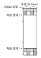
- control information
- resource region
- channel
- subframe
- information
- Prior art date
- Legal status (The legal status is an assumption and is not a legal conclusion. Google has not performed a legal analysis and makes no representation as to the accuracy of the status listed.)
- Ceased
Links
Images




Classifications
-
- H—ELECTRICITY
- H04—ELECTRIC COMMUNICATION TECHNIQUE
- H04L—TRANSMISSION OF DIGITAL INFORMATION, e.g. TELEGRAPHIC COMMUNICATION
- H04L5/00—Arrangements affording multiple use of the transmission path
-
- H—ELECTRICITY
- H04—ELECTRIC COMMUNICATION TECHNIQUE
- H04L—TRANSMISSION OF DIGITAL INFORMATION, e.g. TELEGRAPHIC COMMUNICATION
- H04L25/00—Baseband systems
- H04L25/02—Details ; arrangements for supplying electrical power along data transmission lines
Definitions
- the present disclosure relates to wireless communication, and more particularly, to a method for transmitting uplink control information in a wireless communication system and a device using the same.
- Wireless communication systems have been studied to support higher data rates in order to meet the increasing demand for wireless data traffic.
- One such method is to use a beamforming-based base station that utilizes a wide frequency band in the millimeter wave (mmWave) band can be expected to dramatically increase the capacity of the cellular system.
- mmWave millimeter wave
- multiple digital path (RF) or RF in a multiple input multiple output (MIMO) system that is considered in the existing standard such as Long Term Evolution (LTE) -Advanced It has a (Radio Frequency) chain.
- LTE Long Term Evolution
- MIMO multiple input multiple output
- performance gains such as diversity gain or multiplexing gain can be obtained.
- problems such as synchronization between the digital paths, costs, and operational complexity may occur.
- the present specification provides a method and apparatus for transmitting uplink control information in a wireless communication system.
- the present specification proposes a method for transmitting uplink control information in a wireless communication system.
- the first UL control information may correspond to uplink control information transmitted through control channel 1, but may be used in combination with control channel 1.
- the second UL control information may correspond to uplink control information transmitted through control channel 2 but may be used in combination with control channel 2.
- DL control information can be used interchangeably with a downlink channel.
- the first resource zone may correspond to resource zone 1, and the second resource zone may correspond to resource zone 2.
- the uplink channel may include an uplink control channel or an uplink data channel.
- the downlink channel may include a downlink control channel or a downlink data channel.
- the terminal receives allocation information of the first resource region and the second resource region from the base station.
- the terminal transmits the first UL control information through the first resource region to the base station.
- the terminal transmits the second UL control information through the second resource region to the base station.
- Frequency hopping is performed in the first resource region in a first band which is both end bands of the entire band of the subframe. Alternatively, frequency hopping may be performed in the first resource region in a first band that is both ends of the entire band of the slot or the mini slot. Frequency hopping is performed in the second resource region in a second band which is a subband of the entire band of the subframe. Alternatively, frequency hopping may be performed in the second resource region in the second band, which is both ends of the entire band of the slot or the mini slot. That is, the second resource region is disposed in the band between the first resource region. When a random access resource exists, the random access resource may be disposed between the second resource regions. In this case, the entire band may correspond to the system band.
- the present specification will be described based on subframes, but embodiments described later may be applied to a slot or a mini slot.
- the subframe may correspond to a self-contained frame. That is, in the subframe, a symbol for transmitting downlink (DL) control information, a symbol for transmitting data, and a symbol for transmitting first UL control information or second UL control information are arranged in a time division multiplex (TDM) scheme. .
- TDM time division multiplex
- the first UL control information is used when the quality of an uplink channel cannot be estimated using the DL control information. Accordingly, frequency hopping is performed in both end bands of the entire band of the subframe in the first resource region in which the first UL control information is transmitted, so as to obtain the maximum frequency diversity gain.
- the second UL control information is used when estimating the quality of the uplink channel using the DL control information. This is because the similarity between the uplink control channel and the downlink data channel according to the channel reciprocity characteristic by the self-contained frame is increased.
- the base station allocates a second resource region by roughly estimating the quality information of the uplink channel of the terminal, and views the uplink channel using a reference signal included in the second UL control information transmitted through the second resource region. It can be estimated in detail.
- data may be transmitted through an estimated uplink channel using the second UL control information.
- the second UL control information includes a reference signal used to estimate the uplink channel.
- a sounding reference signal used to estimate the uplink channel is transmitted in the first resource region and the second resource region. That is, the sounding reference signal is used to estimate the uplink channel regardless of the resource region.
- the uplink channel may be estimated using the reference signal included in the second UL control information, the transmission frequency of the sounding reference signal may be reduced.
- allocation information of the second resource region may be received using information on a downlink channel estimated using the DL control information.
- the first UL control information includes scheduling request information or ACK / NACK information of HARQ.
- the second UL control information includes ACK / NACK information of CSI or HARQ. Since CSI has a characteristic of being periodically transmitted, a reference signal of a resource block through which CSI is transmitted is used for estimating an uplink channel. To this end, frequency hopping is performed on a resource block in which CSI is transmitted in a partial band (second band).
- the frequency hopping interval of the first resource region is set equally or differentially. Also, the frequency hopping interval of the second resource region is equally or differentially set. If the frequency hopping interval is set equally, terminals allocated to resource region 1 or resource region 2 may obtain the same level of frequency diversity gain. If the frequency hopping interval is differentially set, a resource region 1 or resource region 2 having the largest frequency hopping interval (the largest frequency diversity gain) may be allocated to a terminal having a poor channel state.
- frequency hopping in the second band is performed in the slot or mini slot unit of the subframe, in the subframe unit, or in the slot unit and the subframe unit of the subframe. Can be performed.
- frequency hopping may be performed by narrowing the frequency interval as described above.
- the present specification proposes an apparatus for transmitting uplink control information in a wireless communication system.
- the first UL control information may correspond to uplink control information transmitted through control channel 1, but may be used in combination with control channel 1.
- the second UL control information may correspond to uplink control information transmitted through control channel 2 but may be used in combination with control channel 2.
- DL control information can be used interchangeably with a downlink channel.
- the first resource zone may correspond to resource zone 1, and the second resource zone may correspond to resource zone 2.
- the uplink channel may include an uplink control channel or an uplink data channel.
- the downlink channel may include a downlink control channel or a downlink data channel.
- the device may be a terminal.
- the apparatus includes a radio frequency (RF) unit for transmitting and receiving radio signals and a processor coupled to the RF unit.
- the processor first receives allocation information of the first resource region and the second resource region from the base station.
- the processor also transmits first UL control information to the base station through the first resource region.
- the processor also transmits second UL control information to the base station through the second resource region.
- RF radio frequency
- Frequency hopping is performed in the first resource region in a first band which is both end bands of the entire band of the subframe. Alternatively, frequency hopping may be performed in the first resource region in a first band that is both ends of the entire band of the slot or the mini slot. Frequency hopping is performed in the second resource region in a second band which is a subband of the entire band of the subframe. Alternatively, frequency hopping may be performed in the second resource region in the second band, which is both ends of the entire band of the slot or the mini slot. That is, the second resource region is disposed in the band between the first resource region. The second resource region may include at least one random access resource. In this case, the entire band may correspond to the system band.
- the present specification will be described based on subframes, but embodiments described later may be applied to a slot or a mini slot.
- the subframe may correspond to a self-contained frame. That is, in the subframe, a symbol for transmitting downlink (DL) control information, a symbol for transmitting data, and a symbol for transmitting first UL control information or second UL control information are arranged in a time division multiplex (TDM) scheme. .
- TDM time division multiplex
- the first UL control information is used when the quality of an uplink channel cannot be estimated using the DL control information. Accordingly, frequency hopping is performed in both end bands of the entire band of the subframe in the first resource region in which the first UL control information is transmitted, so as to obtain the maximum frequency diversity gain.
- the second UL control information is used when estimating the quality of the uplink channel using the DL control information. This is because the similarity between the uplink control channel and the downlink data channel according to the channel reciprocity characteristic by the self-contained frame is increased.
- the base station allocates a second resource region by roughly estimating the quality information of the uplink channel of the terminal, and views the uplink channel using a reference signal included in the second UL control information transmitted through the second resource region. It can be estimated in detail.
- data may be transmitted through an estimated uplink channel using the second UL control information.
- the second UL control information includes a reference signal used to estimate the uplink channel.
- a sounding reference signal used to estimate the uplink channel is transmitted in the first resource region and the second resource region. That is, the sounding reference signal is used to estimate the uplink channel regardless of the resource region.
- the uplink channel may be estimated using the reference signal included in the second UL control information, the transmission frequency of the sounding reference signal may be reduced.
- allocation information of the second resource region may be received using information on a downlink channel estimated using the DL control information.
- the first UL control information includes scheduling request information or ACK / NACK information of HARQ.
- the second UL control information includes ACK / NACK information of CSI or HARQ. Since CSI has a characteristic of being periodically transmitted, a reference signal of a resource block through which CSI is transmitted is used for estimating an uplink channel. To this end, frequency hopping is performed on a resource block in which CSI is transmitted in a partial band (second band).
- the frequency hopping interval of the first resource region is set equally or differentially. Also, the frequency hopping interval of the second resource region is equally or differentially set. If the frequency hopping interval is set equally, terminals allocated to resource region 1 or resource region 2 may obtain the same level of frequency diversity gain. If the frequency hopping interval is differentially set, a resource region 1 or resource region 2 having the largest frequency hopping interval (the largest frequency diversity gain) may be allocated to a terminal having a poor channel state.
- frequency hopping in the second band is performed in the slot or mini slot unit of the subframe, in the subframe unit, or in the slot unit and the subframe unit of the subframe. Can be performed.
- frequency hopping may be performed by narrowing the frequency interval as described above.
- Using the technique of the present specification has an advantage of increasing the reliability of the uplink control signal since the uplink control channel is transmitted in the resource selected in consideration of the channel state for each terminal.
- the characteristics of the uplink data channel are estimated using the reference signal when the uplink control channel is transmitted, there is an advantage of reducing the transmission frequency of an uplink reference signal such as an SRS.
- uplink control information can be stably transmitted even if the channel state for each terminal is not known by using a separate resource for maximizing frequency diversity.
- 1 shows a structure of a radio frame in 3GPP LTE.
- FIG. 2 is an exemplary diagram illustrating a resource grid for one uplink slot in 3GPP LTE.
- 3 shows an example of a structure of a downlink subframe in 3GPP LTE.
- FIG. 5 shows an example of an antenna array based antenna structure and a single beam.
- FIG. 6 illustrates an example of an antenna array based antenna structure and a multi beam.
- FIG. 7 is a diagram illustrating a wide beam using a plurality of narrow beams.
- FIG 8 shows an example of a structure of a synchronization subframe including a synchronization signal and a BRS according to an embodiment of the present specification.
- FIG. 9 illustrates an example of a structure of a self-contained frame in a TDD communication system according to an embodiment of the present specification.
- FIG. 10 illustrates an example in which resource region 1 and resource region 2 are arranged when there is no resource for random access according to an embodiment of the present specification.
- FIG 11 illustrates an example in which resource region 1 and resource region 2 are disposed when there is one resource for random access according to an embodiment of the present specification.
- FIG. 12 illustrates an example in which resource region 1 and resource region 2 are arranged when there are a plurality of random access resources according to an embodiment of the present specification.
- FIG. 13 illustrates an example of differentially configuring a frequency hopping interval of resource region 1 according to an embodiment of the present specification.
- FIG. 14 illustrates an example of equally configuring a frequency hopping interval of resource region 1 according to an embodiment of the present specification.
- 15 shows an example of configuring a frequency hopping interval of resource region 2 according to an embodiment of the present specification.
- 16 is a flowchart illustrating a procedure for transmitting uplink control information according to an embodiment of the present specification.
- 17 is a block diagram illustrating a device in which an embodiment of the present specification is implemented.
- CDMA code division multiple access
- FDMA frequency division multiple access
- TDMA time division multiple access
- OFDMA orthogonal frequency division multiple access
- SC-FDMA single carrier-frequency division multiple access
- CDMA may be implemented with a radio technology such as Universal Terrestrial Radio Access (UTRA) or CDMA2000.
- TDMA may be implemented with wireless technologies such as Global System for Mobile communications (GSM) / General Packet Radio Service (GPRS) / Enhanced Data Rates for GSM Evolution (EDGE).
- GSM Global System for Mobile communications
- GPRS General Packet Radio Service
- EDGE Enhanced Data Rates for GSM Evolution
- OFDMA may be implemented in a wireless technology such as IEEE 802.11 (Wi-Fi), IEEE 802.16 (WiMAX), IEEE 802-20, Evolved UTRA (E-UTRA).
- UTRA is part of the Universal Mobile Telecommunications System (UMTS).
- 3rd Generation Partnership Project (3GPP) long term evolution (LTE) is part of an Evolved UMTS (E-UMTS) using E-UTRA, and employs OFDMA in downlink and SC-FDMA in uplink.
- 3GPP 3rd Generation Partnership Project
- LTE long term evolution
- E-UMTS Evolved UMTS
- 1 shows a structure of a radio frame in 3GPP LTE.
- a radio frame consists of 10 subframes, and one subframe consists of two slots. Slots in a radio frame are numbered from 0 to 19 slots.
- the time taken for one subframe to be transmitted is called a transmission time interval (TTI).
- TTI may be referred to as a scheduling unit for data transmission.
- one radio frame may have a length of 10 ms
- one subframe may have a length of 1 ms
- one slot may have a length of 0.5 ms.
- the structure of the radio frame is merely an example, and the number of subframes included in the radio frame or the number of slots included in the subframe may be variously changed.
- FIG. 2 is an exemplary diagram illustrating a resource grid for one uplink slot in 3GPP LTE.
- an uplink slot includes a plurality of SC-FDMA symbols in a time domain and includes a Nul resource block (RB) in a frequency domain.
- the SC-FDMA symbol is used to represent one symbol period and may be called an OFDMA symbol or a symbol period according to a system.
- the RB includes a plurality of subcarriers in the frequency domain in resource allocation units.
- the number Nul of resource blocks included in the uplink slot depends on the uplink transmission bandwidth set in the cell.
- the uplink transmission bandwidth is system information.
- the terminal may know N ul by acquiring system information.
- Each element on the resource grid is called a resource element.
- an exemplary resource block includes 7 SC-FDMA symbols in the time domain and 7 ⁇ 12 resource elements including 12 subcarriers in the frequency domain, but the number of subcarriers in the resource block and the SC-FDMA symbol are exemplarily described.
- the number of is not limited thereto.
- the number of SC-FDMA symbols or the number of subcarriers included in the RB may be variously changed.
- the number of SC-FDMA symbols may be changed according to the length of a cyclic prefix (CP). For example, the number of SC-FDMA symbols is 7 for a normal CP and the number of SC-FDMA symbols is 6 for an extended CP.
- CP cyclic prefix
- a resource grid for one uplink slot may be applied to a resource grid for a downlink slot.
- the downlink slot includes a plurality of orthogonal frequency division multiplexing (OFDM) symbols in the time domain.
- OFDM orthogonal frequency division multiplexing
- 3 shows an example of a structure of a downlink subframe in 3GPP LTE.
- the downlink subframe includes two contiguous slots. Up to three OFDM symbols of the first slot in the downlink subframe are control regions to which a physical downlink control channel (PDCCH) is allocated, and the remaining OFDM symbols are data regions to which a physical downlink shared channel (PDSCH) is allocated. data region).
- the control region may be allocated a control channel such as a physical control format indicator channel (PCFICH) and a physical hybrid-ARQ indicator channel (PHICH).
- PCFICH physical control format indicator channel
- PHICH physical hybrid-ARQ indicator channel
- the control region includes 3 OFDM symbols.
- the number of OFDM symbols included in the control region in the subframe can be known through the PCFICH.
- the PHICH carries hybrid automatic repeat request (HARQ) acknowledgment (ACK) / not-acknowledgement (NACK) information in response to uplink data transmission.
- HARQ hybrid automatic repeat request
- ACK acknowledgment
- NACK not-acknowledgement
- the PDCCH may carry a downlink grant informing of resource allocation of downlink transmission on the PDSCH.
- the UE may read downlink user data transmitted through the PDSCH by decoding control information transmitted through the PDCCH.
- the PDCCH may carry control information used for physical uplink shared channel (PUSCH) scheduling to the UE.
- the control information used for PUSCH scheduling is an uplink grant informing of resource allocation of uplink transmission.
- the control region consists of a set of a plurality of control channel elements (CCE).
- the PDCCH is transmitted on an aggregation of one or several consecutive CCEs.
- the CCE corresponds to a plurality of resource element groups. Resource element groups are used to define control channel mappings to resource elements. If the total number of CCEs in the downlink subframe is N cce , the CCE is indexed from 0 to N cce , k-1. Since the number of OFDM symbols included in the control region in the subframe may change for each subframe, the total number of CCEs in the subframe may also change for each subframe.
- the uplink subframe may be divided into a control region and a data region in the frequency domain.
- the control region is allocated a Physical Uplink Control Channel (PUCCH) for transmitting uplink control information.
- the data region is allocated a physical uplink shared channel (PUSCH) for transmitting data.
- PUCCH Physical Uplink Control Channel
- PUSCH physical uplink shared channel
- the terminal may support simultaneous transmission of the PUSCH and the PUCCH.
- the uplink data transmitted on the PUSCH may be a transport block which is a data block for the UL-SCH transmitted during the TTI.
- the transport block may be user information.
- the uplink data may be multiplexed data.
- the multiplexed data may be a multiplexed transport block and control information for the UL-SCH.
- control information multiplexed with data may include CQI, PMI (Precoding Matrix Indicator), HARQ, RI (Rank Indicator), and the like.
- the uplink data may consist of control information only.
- PUCCH for one UE is allocated to an RB pair in a subframe.
- Resource blocks belonging to a resource block pair occupy different subcarriers in each of the first slot and the second slot.
- the frequency occupied by the resource block belonging to the resource block pair allocated to the PUCCH is changed based on a slot boundary. This is called that the RB pair allocated to the PUCCH is frequency-hopped at the slot boundary.
- the terminal may obtain a frequency diversity gain by transmitting uplink control information through different subcarriers over time.
- m is a location index indicating a logical frequency domain location of a resource block pair allocated to a PUCCH in a subframe.
- PUCCH carries various kinds of control information according to a format.
- PUCCH format 1 carries a scheduling request (SR). In this case, an OOK (On-Off Keying) method may be applied.
- PUCCH format 1a carries ACK / NACK (Acknowledgement / Non-Acknowledgement) modulated in a Bit Phase Shift Keying (BPSK) scheme for one codeword.
- PUCCH format 1b carries ACK / NACK modulated by Quadrature Phase Shift Keying (QPSK) for two codewords.
- PUCCH format 2 carries a channel quality indicator (CQI) modulated in a QPSK scheme.
- PUCCH formats 2a and 2b carry CQI and ACK / NACK.
- Beamforming may be classified into transmit beamforming performed by a transmitting end and receive beamforming performed by a receiving end.
- the transmission beamforming generally uses multiple antennas to increase the directivity by concentrating the area of arrival of radio waves in a specific direction.
- a form in which a plurality of antennas are collected may be referred to as an antenna array, and each antenna included in the antenna array may be referred to as an array element.
- the antenna array may be configured in various forms such as a linear array and a planar array.
- using the transmission beamforming increases the directivity of the signal, thereby increasing the transmission distance of the signal.
- signal interference with respect to other receivers is greatly reduced at the receiver.
- the receiving end may perform beamforming on the received signal using the receiving antenna array.
- the reception beamforming concentrates the reception of radio waves in a specific direction to increase the sensitivity of the reception signal received in the specific direction, and blocks the interference signal by excluding signals from directions other than the specific direction from the reception signal. to provide.
- FIG. 5 shows an example of an antenna array based antenna structure and a single beam.
- one radio frequency (RF) beam (single beam) is defined using one antenna array including two sub-arrays.
- one sub array is composed of 8 (H) * 8 (V) * 2 (P) antennas (P denotes Xpol) and has two RF chains.
- the width of the one RF beam is 15 '(H) * 15' (V).
- FIG. 6 illustrates an example of an antenna array based antenna structure and a multi beam.
- RF beams (multi beams) having different directions are defined for each RF chain.
- four beams according to each RF chain may cover different areas.
- FIG. 7 is a diagram illustrating a wide beam using a plurality of narrow beams.
- the wide beams may be represented as shown in FIG. 7.
- FIG. 7 shows a wide beam using four sub-arrays.
- a transmitter transmits a synchronization signal using the wide beam. That is, it is assumed that all subarrays transmit the same Primary Synchronization Signal (PSS) / Secondary Synchronization Signal (SSS) / Physical Broadcast Channel (PBCH).
- PSS Primary Synchronization Signal
- SSS Secondary Synchronization Signal
- PBCH Physical Broadcast Channel
- power gain may be additionally provided through repetitive transmission on the time axis.
- the synchronization subframe structure based on such repeated transmission may be represented as shown in FIG. 8.
- FIG 8 shows an example of a structure of a synchronization subframe including a synchronization signal and a BRS according to an embodiment of the present specification.
- a block in which the same shade is indicated refers to an OFDM symbol group to which the same RF beam group (defined using four subarray beams) is applied. That is, four OFDM symbols use the same multi-RF beam.
- a synchronization subframe including a synchronization signal and a BRS Beam Reference Signal
- Reference signals such as Channel State Indicator (CSI) -Reference Signal (RS) include Time Division Multiplexing (TDM), Frequency Division Multiplexing (TDM) for a plurality of beams supported by a base station; FDM) or Code Division Multiplexing (CDM) scheme is transmitted.
- TDM Time Division Multiplexing
- TDM Frequency Division Multiplexing
- CDM Code Division Multiplexing
- the CSI-RS has a wide radiation angle of 120 degrees for each antenna port.
- BRS that can be applied in an embodiment of the present specification is a reference signal for feeding back beam state information for a plurality of beams.
- the BRS can be applied to a sharp beam because the beam radiation angle is smaller than that of the CSI-RS.
- the BRS may be multiplexed by FDM for each antenna port in one symbol and transmitted during at least one subframe.
- the subframe transmitting the BRS may be referred to as a synchronization subframe.
- the synchronization subframe has 12 or 14 symbols and may be transmitted according to a transmission period in which one synchronization subframe is transmitted every 5 ms.
- the synchronization subframe has 14 symbols (two slots) in consideration of the case of a normal CP.
- the symbol may correspond to an OFDM symbol.
- the UE After the UE acquires downlink synchronization using PSS and / or SSS, the UE selects an optimal beam using BRS.
- a synchronization signal such as PSS and / or SSS occupies a relatively small band based on the center frequency.
- BRS occupies the entire system band of the base station, the BRS has an advantage of searching for an optimal beam based on a wideband channel.
- PSS and / or SSS are multiplexed by FDM in one symbol.
- the BRS is also multiplexed by the FDM scheme in one symbol and a synchronization signal such as the PSS and / or SSS.
- the synchronization subframe shown in FIG. 8 may be used to cover the area where the beam emission angle is 120 degrees.
- the PBCH may be multiplexed and transmitted by the FDM scheme together with the BRS.
- the PBCH is a signal for transmitting essential information of the system (for example, system frame number, BRS transmission period configuration, ePBCH transmission indicator, etc.).
- FIG. 9 illustrates an example of a structure of a self-contained frame in a TDD communication system according to an embodiment of the present specification.
- the low latency requirement of the next generation wireless communication system is expected to suggest a data transmission delay of 1ms.
- a structure of a self-contained frame in which a downlink control channel and an uplink control channel always exist in a single subframe has been proposed.
- the structure of the self-contained frame is characterized by time division between the control channel and the data channel. That is, the control channel and the data channel may be arranged in a TDM manner.
- the uplink control channel and the data channel are frequency-divided. Therefore, there is a limit in estimating channel characteristics of an uplink data channel using a reference signal of an uplink control channel.
- the uplink control channel and the data channel are time-divided, it is possible to estimate the channel quality of the data channel using the reference signal of the control channel.
- a technique of hopping a control channel for channel estimation using this feature has been proposed (Method of UL signal transmission for UL channel sounding).
- the quality of the uplink control channel and the data channel can be estimated using the quality information of the downlink channel.
- the above-described scheme increases the similarity between the channels of the uplink control channel and the downlink data channel due to channel reciprocity characteristics.
- Channel estimation for uplink data transmission is possible using a reference signal of the uplink control channel.
- the present specification proposes a scheme of forming an uplink control channel capable of estimating an uplink data channel and increasing the probability of success in transmitting an uplink control channel by forming an uplink control channel in a resource having a good channel state.
- an uplink (UL) control channel is divided into two types. One is the control channel 1 which can be used even before the base station receives the downlink channel characteristics from the terminal, and the other is the control channel 2 which can be used after the base station receives the downlink channel characteristics. After the base station receives the downlink channel characteristics, transmitting uplink control information in a band where channel quality is expected to be good using channel reciprocity of a time division duplex (TDD) is a signal transmission probability. Can be further increased. In addition, it is possible to perform uplink channel estimation using a reference signal transmitted together when transmitting uplink control information within a corresponding band.
- TDD time division duplex
- the uplink control information is transmitted through the uplink control channel, but can be used in combination with the uplink control channel.
- the uplink data is transmitted through the uplink data channel, but can be used in combination with the uplink data channel.
- FIG. 10 illustrates an example in which resource region 1 and resource region 2 are arranged when there is no resource for random access according to an embodiment of the present specification.
- the allocated resource region may be changed according to the content of control information transmitted through the uplink control channel. That is, a resource region for transmitting uplink control information may be divided into a resource region 1 and a resource region 2 as shown in FIG. 10. Resource zone 1 is located at the far end of the system band and resource zone 2 is located in the inner band of resource zone 1.
- the uplink control channel is divided into control channel 1 and control channel 2 according to the content of information, control channel 1 is transmitted in resource region 1, and control channel 2 is transmitted in resource region 2.
- the mapping relationship between the control channel and the resource region is determined by the characteristics of the system or the base station is transmitted to the terminal as system information.
- Resource region 1 is designed to be used even when the base station cannot predict the uplink channel quality. Therefore, it is proposed to be located at both ends of the system band so that frequency diversity gain can be obtained as much as possible.
- the resource region 2 is located in the inner band of the resource region 1, and when the base station predicts the uplink channel quality of the terminal, the uplink control channel of the terminal is formed in a subband. As a result, the base station can more stably receive the uplink reception signal.
- uplink channel information may be estimated in detail using a reference signal of uplink control information (control signal) transmitted in the partial band. In a broadband system, since the partial band may be several MHz or tens of MHz, it may be necessary to select a resource for uplink data transmission even within the subband.
- 11 illustrates an example in which resource region 1 and resource region 2 are disposed when there is one resource for random access according to an embodiment of the present specification.
- 12 illustrates an example in which resource region 1 and resource region 2 are arranged when there are a plurality of random access resources according to an embodiment of the present specification.
- RACH resource a random access resource
- Resource zone 1 is disposed at both ends of the system band, and a resource for random access and resource zone 2 are arranged between the resource zones 1. The same applies to the RACH dedicated subframe of the high frequency transmission system.
- control channel 1 includes information that should be transmitted even when uplink channel estimation is not performed or channel estimation is incorrect.
- the scheduling request is transmitted even when the terminal is not active, the base station must operate stably even when the base station does not have uplink channel channel information of the terminal. Therefore, the scheduling request is preferably transmitted on the control channel 1 to obtain the maximum frequency diversity.
- the ACK / NACK of HARQ should be transmitted stably even when the UE fails in downlink reception.
- the base station allocates an uplink control channel based on the quality information of the downlink control channel, if the terminal fails to receive the downlink data due to channel reciprocity, the base station may fail to receive the ACK / NACK of the HARQ. The probability can also be high.
- format 1 is a format for transmitting a scheduling request
- format 2 is a format for transmitting ACK / NACK of HARQ
- format 3 is a format of scheduling request and HARQ. It can be set as a format for transmitting ACK / NACK.
- format 4 may be set as a format for transmitting CQI.
- Control channel 2 includes uplink control information having a periodic characteristic. This is to estimate an uplink channel for data transmission using a reference signal transmitted on control channel 2.
- Control channel 2 is transmitted in a partial band where the uplink channel quality is expected to be excellent when the base station can predict the uplink channel quality of the terminal. Therefore, it is possible to perform channel estimation for uplink data transmission in detail using a reference signal during control channel 2 transmission.
- uplink control information signal
- channel state information such as CQI, PMI, RI
- format 1 is set as a format for transmitting channel state information (CSI) such as CQI, PMI, and RI
- format 2 is channel state information and scheduling request. You can set the format for the transfer.
- format 3 may be set as a format for transmitting channel state information and ACK / NACK of HARQ
- format 4 may be set as a format for transmitting scheduling request and ACK / NACK of HARQ.
- FIG. 13 illustrates an example of differentially configuring a frequency hopping interval of resource region 1 according to an embodiment of the present specification.
- 14 illustrates an example of equally configuring a frequency hopping interval of resource region 1 according to an embodiment of the present specification.
- Resource region 1 is composed of a resource block.
- frequency hopping is performed in units of resource blocks within the same subframe.
- Resource region 1 aims to obtain a frequency diversity gain in transmitting a single signal. Therefore, it is necessary to perform frequency hopping in the same subframe so that frequency diversity can be obtained during signal transmission.
- hopping is performed in units of slots.
- the slot length may be n OFDM symbols.
- n may have a value of 1/2 ⁇ x as well as an integer such as 0.5, 0.25, and 0.125.
- x is an integer.
- the uplink control channel may consist of one OFDM symbol.
- the length of the slot in order to perform slot unit frequency hopping in a single subframe, the length of the slot must be shorter than the length of the OFDM symbol.
- the length of an OFDM symbol constituting a slot should be 1/2 ⁇ x due to the nature of FFT / IFFT.
- the frequency hopping intervals of all resources are set equally or differentially. As shown in FIG. 14, if the frequency hopping intervals of all resources are set to be the same, terminals allocated to the resource region 1 have an advantage of obtaining the same level of frequency diversity on average. On the other hand, if the frequency hopping interval of the resource is configured differentially (for example, PUCCH in the LTE system) as shown in FIG. Therefore, a resource having a maximum value of frequency diversity can be allocated to a terminal having a poor channel situation.
- the frequency hopping interval of the resource is configured differentially (for example, PUCCH in the LTE system) as shown in FIG. Therefore, a resource having a maximum value of frequency diversity can be allocated to a terminal having a poor channel situation.
- 15 shows an example of configuring a frequency hopping interval of resource region 2 according to an embodiment of the present specification.
- the resource region 2 is composed of partial bands, and the partial band is composed of resource blocks.
- frequency hopping is performed in units of resource blocks within the same subband.
- the partial band of the resource region 2 to which control channel 2 is allocated in the system may be in units of several tens of MHz. Therefore, the UE may set a partial band for transmitting the uplink control channel and perform frequency hopping in the partial band.
- Performing frequency hopping in the partial band has the advantage of obtaining frequency diversity, but also has the purpose of precisely performing the uplink channel estimation in the partial band.
- the frequency hopping of the resource region 2 may be performed in a slot unit, in a subframe unit, or in both a slot and subframe unit in a subframe.
- the resource region 2 Since the resource region 2 has a purpose for uplink channel estimation, it is necessary to shorten a subcarrier interval for transmitting an uplink reference signal.
- the frequency interval for performing hopping should be tight. Therefore, it is necessary to perform frequency hopping not only in the subframe but also in the subframe unit. 15 is an embodiment where frequency hopping is performed in both slots and subframes.
- the frequency hopping interval of all resources may be set equally or differentially. If the frequency hopping intervals of all resources are set to be the same, uplink channel estimation is easy because the reference signals are transmitted at equal intervals.
- the UEs allocated to the resource region 2 have an advantage of obtaining the same level of frequency diversity on average.
- the differential configuration of the frequency hopping interval (for example, PUCCH in LTE system) has the advantage that the maximum value of the frequency diversity that the terminal can obtain. Therefore, a resource having a maximum value of frequency diversity can be allocated to a terminal having a poor channel situation.
- the operation of the base station for resource allocation of control channel 2 is as follows.
- the base station transmits downlink channel information estimated by the terminal using the downlink reference signal
- the base station transmits a signal for allocating a partial band of the control channel 2 to the terminal using the downlink channel information.
- the base station transmits a full-band sounding reference signal (SRS) to the terminal and collects uplink control channel information. Thereafter, based on the collected information, a signal for subband allocation of control channel 2 is transmitted.
- SRS sounding reference signal
- the terminal may be allocated resource region 1 and resource region 2 simultaneously from the base station. For example, the UE may transmit a scheduling request and an ACK / NACK signal of HARQ on control channel 1 and transmit channel state information on control channel 2. In this case, the terminal is allocated control channel 1 to resource region 1 and control channel 2 to resource region 2 through device specific signaling.
- a sounding reference signal (SRS) whose primary purpose is uplink channel estimation may be set in both resource region 1 and resource region 2.
- uplink data can be transmitted in all subcarriers in which resource region 1 and resource region 2 are transmitted. Therefore, the SRS for uplink channel estimation needs to be transmitted in both resource region 1 and resource region 2.
- 16 is a flowchart illustrating a procedure for transmitting uplink control information according to an embodiment of the present specification.
- the first UL control information may correspond to uplink control information transmitted through control channel 1, but may be used in combination with control channel 1.
- the second UL control information may correspond to uplink control information transmitted through control channel 2 but may be used in combination with control channel 2.
- DL control information can be used interchangeably with a downlink channel.
- the first resource zone may correspond to resource zone 1, and the second resource zone may correspond to resource zone 2.
- the uplink channel may include an uplink control channel or an uplink data channel.
- the downlink channel may include a downlink control channel or a downlink data channel.
- step S1610 the terminal receives allocation information of the first resource region and the second resource region from the base station.
- step S1620 the terminal transmits the first UL control information through the first resource region to the base station.
- step S1630 the terminal transmits the second UL control information through the second resource region to the base station.
- Frequency hopping is performed in the first resource region in a first band which is both end bands of the entire band of the subframe. Alternatively, frequency hopping may be performed in the first resource region in a first band that is both ends of the entire band of the slot or the mini slot. Frequency hopping is performed in the second resource region in a second band which is a subband of the entire band of the subframe. Alternatively, frequency hopping may be performed in the second resource region in the second band, which is both ends of the entire band of the slot or the mini slot. That is, the second resource region is disposed in the band between the first resource region. When a random access resource exists, the random access resource may be disposed between the second resource regions. In this case, the entire band may correspond to the system band.
- the subframe may correspond to a self-contained frame. That is, in the subframe, a symbol for transmitting downlink (DL) control information, a symbol for transmitting data, and a symbol for transmitting first UL control information or second UL control information are arranged in a time division multiplex (TDM) scheme. .
- TDM time division multiplex
- the first UL control information is used when the quality of an uplink channel cannot be estimated using the DL control information. Accordingly, frequency hopping is performed in both end bands of the entire band of the subframe in the first resource region in which the first UL control information is transmitted, so as to obtain the maximum frequency diversity gain.
- the second UL control information is used when estimating the quality of the uplink channel using the DL control information. This is because the similarity between the uplink control channel and the downlink data channel according to the channel reciprocity characteristic by the self-contained frame is increased.
- the base station allocates a second resource region by roughly estimating the quality information of the uplink channel of the terminal, and views the uplink channel using a reference signal included in the second UL control information transmitted through the second resource region. It can be estimated in detail.
- data may be transmitted through an estimated uplink channel using the second UL control information.
- the second UL control information includes a reference signal used to estimate the uplink channel.
- a sounding reference signal used to estimate the uplink channel is transmitted in the first resource region and the second resource region. That is, the sounding reference signal is used to estimate the uplink channel regardless of the resource region.
- the uplink channel may be estimated using the reference signal included in the second UL control information, the transmission frequency of the sounding reference signal may be reduced.
- allocation information of the second resource region may be received using information on a downlink channel estimated using the DL control information.
- the first UL control information includes scheduling request information or ACK / NACK information of HARQ.
- the second UL control information includes ACK / NACK information of CSI or HARQ. Since CSI has a characteristic of being periodically transmitted, a reference signal of a resource block through which CSI is transmitted is used for estimating an uplink channel. To this end, frequency hopping is performed on a resource block in which CSI is transmitted in a partial band (second band).
- the frequency hopping interval of the first resource region is set equally or differentially. Also, the frequency hopping interval of the second resource region is equally or differentially set. If the frequency hopping interval is set equally, terminals allocated to resource region 1 or resource region 2 may obtain the same level of frequency diversity gain. If the frequency hopping interval is differentially set, a resource region 1 or resource region 2 having the largest frequency hopping interval (the largest frequency diversity gain) may be allocated to a terminal having a poor channel state.
- frequency hopping in the second band is performed in the slot or mini slot unit of the subframe, in the subframe unit, or in the slot unit and the subframe unit of the subframe. Can be performed.
- frequency hopping may be performed by narrowing the frequency interval as described above.
- 17 is a block diagram illustrating a device in which an embodiment of the present specification is implemented.
- the wireless device 17000 may include a processor 1710, a memory 1720, and a radio frequency (RF) unit 1730.
- the processor 1710 may be configured to implement the above-described functions, procedures, and methods. Layers of a radio interface protocol may be implemented in a processor. The processor 1710 may perform a procedure for driving the above-described operation.
- the memory 1720 is operatively connected to the processor 1710, and the RF unit 1730 is operatively connected to the processor 1710.
- the processor 1710 may include an application-specific integrated circuit (ASIC), another chipset, a logic circuit, and / or a data processing device.
- Memory 1720 may include read-only memory (ROM), random access memory (RAM), flash memory, memory cards, storage media, and / or other storage devices.
- the RF unit 1730 may include a baseband circuit for processing a radio signal.
- the above-described technique may be implemented as a module (process, function, etc.) for performing the above-described function.
- the module may be stored in the memory 1720 and executed by the processor 1710.
- the memory 1720 may be inside or outside the processor 1710 and may be connected to the processor 1710 through various well-known means.
Landscapes
- Engineering & Computer Science (AREA)
- Signal Processing (AREA)
- Computer Networks & Wireless Communication (AREA)
- Power Engineering (AREA)
- Mobile Radio Communication Systems (AREA)
Abstract
La présente invention concerne un procédé et un appareil pour transmettre des informations de commande de liaison montante (UL) dans un système de communication sans fil. Spécifiquement, un terminal reçoit des informations d'attribution d'une première région de ressources et d'une seconde région de ressources. Le terminal transmet des premières informations de commande de liaison montante par le biais de la première région de ressources. Le terminal transmet des secondes informations de commande de liaison montante par le biais de la seconde région de ressources. La première région de ressources est une région à sauts de fréquence dans des premières bandes qui sont aux deux extrémités de la bande complète d'une sous-trame tandis que la seconde région de ressources est une région à sauts de fréquence dans une seconde bande qui est une bande partielle de la sous-trame. Dans la sous-trame, un symbole pour transmettre des informations de commande de liaison descendante, un symbole pour transmettre des données et un symbole pour transmettre les premières informations de commande de liaison montante ou les secondes informations de commande de liaison montante sont agencés selon un multiplexage par répartition dans le temps.
Applications Claiming Priority (2)
| Application Number | Priority Date | Filing Date | Title |
|---|---|---|---|
| US201662320614P | 2016-04-10 | 2016-04-10 | |
| US62/320,614 | 2016-04-10 |
Publications (2)
| Publication Number | Publication Date |
|---|---|
| WO2017179833A2 true WO2017179833A2 (fr) | 2017-10-19 |
| WO2017179833A3 WO2017179833A3 (fr) | 2018-09-07 |
Family
ID=60041992
Family Applications (1)
| Application Number | Title | Priority Date | Filing Date |
|---|---|---|---|
| PCT/KR2017/003205 Ceased WO2017179833A2 (fr) | 2016-04-10 | 2017-03-24 | Procédé et appareil pour transmettre des informations de commande de liaison montante dans un système de communication sans fil |
Country Status (1)
| Country | Link |
|---|---|
| WO (1) | WO2017179833A2 (fr) |
Family Cites Families (2)
| Publication number | Priority date | Publication date | Assignee | Title |
|---|---|---|---|---|
| KR101633964B1 (ko) * | 2010-08-20 | 2016-06-27 | 텔레폰악티에볼라겟엘엠에릭슨(펍) | Pucch 포맷 3 리소스를 식별하기 위한 장치 및 방법 |
| WO2014007531A1 (fr) * | 2012-07-05 | 2014-01-09 | 주식회사 케이티 | Procédé de commande de transmission en liaison montante dans un réseau de communication mobile et appareil associé |
-
2017
- 2017-03-24 WO PCT/KR2017/003205 patent/WO2017179833A2/fr not_active Ceased
Also Published As
| Publication number | Publication date |
|---|---|
| WO2017179833A3 (fr) | 2018-09-07 |
Similar Documents
| Publication | Publication Date | Title |
|---|---|---|
| WO2017188733A1 (fr) | Procédé et appareil destinés à configurer une structure de trame pour une nouvelle technologie d'accès radio dans un système de communication sans fil | |
| WO2010013961A2 (fr) | Procédé et dispositif de supervision de canal pdcch dans un système de communications sans fil | |
| WO2018004251A1 (fr) | Procédé de réception d'un signal de liaison descendante et équipement d'utilisateur, et procédé d'émission d'un signal de liaison descendante et station de base | |
| WO2010068047A2 (fr) | Procédé et appareil pour transmettre un signal de référence produit par une station relais dans un système de communication sans fil | |
| WO2019031952A1 (fr) | Procédé et dispositif pour qu'un terminal v2x reçoive des informations de planification de canal pscch et transmette un canal pscch dans un système de communication sans fil | |
| WO2017183848A1 (fr) | Procédé et appareil permettant de transmettre des données de liaison montante dans un système de communication sans fil | |
| WO2013015636A2 (fr) | Appareil et procédé de formation de faisceaux dans un système de communication sans fil | |
| WO2016068542A2 (fr) | Procédé de transmission de pucch par un dispositif mtc | |
| WO2018030791A1 (fr) | Procédé et appareil permettant à un terminal de transmettre des données de d2d dans un système de communication sans fil | |
| WO2017048099A1 (fr) | Procédé et appareil d'émission/réception de messages provenant d'un terminal v2x dans un système de communication sans fil | |
| WO2017099526A1 (fr) | Procédé de réception de canal de liaison descendante et équipement utilisateur, et procédé de transmission de canal de liaison descendante et station de base | |
| WO2018021825A1 (fr) | Procédé d'émission de signal de liaison montante et équipement utilisateur, et procédé de réception de signal de liaison montante et station de base | |
| WO2013162321A2 (fr) | Procédé de transmission et de réception de signal, et appareil correspondant | |
| WO2017209547A1 (fr) | Procédé de réception de signaux en liaison descendante et équipement d'utilisateur, et procédé d'émission de signaux en liaison descendante et station de base | |
| WO2018030813A1 (fr) | Procédé et dispositif d'émission et de réception d'un signal sans fil dans un système de communication sans fil | |
| WO2017196108A2 (fr) | Procédé de réception de signaux en liaison descendante et équipement d'utilisateur, et procédé de transmission de signaux en liaison descendante et station de base | |
| WO2018056775A1 (fr) | Procédé de transmission de signal de liaison montante et équipement utilisateur, et procédé de réception de signal de liaison montante et station de base | |
| WO2013069903A1 (fr) | Procédé de mise en correspondance de e-pdcch, et procédé et appareil pour la transmission et la réception dans un système de communication sans fil | |
| WO2018070776A1 (fr) | Procédé et appareil de réduction de la latence sur la base d'un canal partagé de liaison montante physique préconfiguré dans un système de communication sans fil | |
| WO2018016828A1 (fr) | Procédé et équipement d'utilisateur pour recevoir un signal de liaison descendante, et procédé et station de base pour transmettre un signal de liaison descendante | |
| WO2018230902A1 (fr) | Procédé de réception de canal de commande de liaison descendante et dispositif associé | |
| WO2018009037A1 (fr) | Procédé et appareil permettant la signalisation d'une capacité d'un équipement utilisateur relative à une nouvelle technologie d'accès radio dans un système de communication sans fil | |
| WO2017188729A2 (fr) | Procédé de réception de signal de liaison descendante et équipement utilisateur, et procédé d'émission de signal de liaison descendante et station de base | |
| WO2018217073A1 (fr) | Procédé de sélection de ressource de transmission destinée à un bloc de transport par un équipement utilisateur dans un système de communication sans fil et appareil associé | |
| WO2018186647A1 (fr) | Procédé de réception de signal de référence et équipement utilisateur, et procédé de transmission de signal de référence et station de base |
Legal Events
| Date | Code | Title | Description |
|---|---|---|---|
| NENP | Non-entry into the national phase in: |
Ref country code: DE |
|
| 121 | Ep: the epo has been informed by wipo that ep was designated in this application |
Ref document number: 17782588 Country of ref document: EP Kind code of ref document: A2 |
|
| 122 | Ep: pct application non-entry in european phase |
Ref document number: 17782588 Country of ref document: EP Kind code of ref document: A2 |