WO2017179920A2 - 스프레이어 가이드 삽입부가 있는 캡슐장치 - Google Patents
스프레이어 가이드 삽입부가 있는 캡슐장치 Download PDFInfo
- Publication number
- WO2017179920A2 WO2017179920A2 PCT/KR2017/003993 KR2017003993W WO2017179920A2 WO 2017179920 A2 WO2017179920 A2 WO 2017179920A2 KR 2017003993 W KR2017003993 W KR 2017003993W WO 2017179920 A2 WO2017179920 A2 WO 2017179920A2
- Authority
- WO
- WIPO (PCT)
- Prior art keywords
- capsule
- sprayer
- container
- guide
- annulus
- Prior art date
- Legal status (The legal status is an assumption and is not a legal conclusion. Google has not performed a legal analysis and makes no representation as to the accuracy of the status listed.)
- Ceased
Links
Images



Classifications
-
- B—PERFORMING OPERATIONS; TRANSPORTING
- B05—SPRAYING OR ATOMISING IN GENERAL; APPLYING FLUENT MATERIALS TO SURFACES, IN GENERAL
- B05B—SPRAYING APPARATUS; ATOMISING APPARATUS; NOZZLES
- B05B11/00—Single-unit hand-held apparatus in which flow of contents is produced by the muscular force of the operator at the moment of use
- B05B11/0005—Components or details
- B05B11/0078—Arrangements for separately storing several components
- B05B11/0081—Arrangements for separately storing several components and for mixing the components in a common container as a mixture ready for use before discharging the latter
-
- B—PERFORMING OPERATIONS; TRANSPORTING
- B65—CONVEYING; PACKING; STORING; HANDLING THIN OR FILAMENTARY MATERIAL
- B65D—CONTAINERS FOR STORAGE OR TRANSPORT OF ARTICLES OR MATERIALS, e.g. BAGS, BARRELS, BOTTLES, BOXES, CANS, CARTONS, CRATES, DRUMS, JARS, TANKS, HOPPERS, FORWARDING CONTAINERS; ACCESSORIES, CLOSURES, OR FITTINGS THEREFOR; PACKAGING ELEMENTS; PACKAGES
- B65D25/00—Details of other kinds or types of rigid or semi-rigid containers
- B65D25/38—Devices for discharging contents
- B65D25/40—Nozzles or spouts
-
- B—PERFORMING OPERATIONS; TRANSPORTING
- B65—CONVEYING; PACKING; STORING; HANDLING THIN OR FILAMENTARY MATERIAL
- B65D—CONTAINERS FOR STORAGE OR TRANSPORT OF ARTICLES OR MATERIALS, e.g. BAGS, BARRELS, BOTTLES, BOXES, CANS, CARTONS, CRATES, DRUMS, JARS, TANKS, HOPPERS, FORWARDING CONTAINERS; ACCESSORIES, CLOSURES, OR FITTINGS THEREFOR; PACKAGING ELEMENTS; PACKAGES
- B65D51/00—Closures not otherwise provided for
- B65D51/24—Closures not otherwise provided for combined or co-operating with auxiliary devices for non-closing purposes
- B65D51/28—Closures not otherwise provided for combined or co-operating with auxiliary devices for non-closing purposes with auxiliary containers for additional articles or materials
-
- B—PERFORMING OPERATIONS; TRANSPORTING
- B65—CONVEYING; PACKING; STORING; HANDLING THIN OR FILAMENTARY MATERIAL
- B65D—CONTAINERS FOR STORAGE OR TRANSPORT OF ARTICLES OR MATERIALS, e.g. BAGS, BARRELS, BOTTLES, BOXES, CANS, CARTONS, CRATES, DRUMS, JARS, TANKS, HOPPERS, FORWARDING CONTAINERS; ACCESSORIES, CLOSURES, OR FITTINGS THEREFOR; PACKAGING ELEMENTS; PACKAGES
- B65D81/00—Containers, packaging elements, or packages, for contents presenting particular transport or storage problems, or adapted to be used for non-packaging purposes after removal of contents
- B65D81/32—Containers, packaging elements, or packages, for contents presenting particular transport or storage problems, or adapted to be used for non-packaging purposes after removal of contents for packaging two or more different materials which must be maintained separate prior to use in admixture
Definitions
- the present invention is a container equipped with a trigger sprayer (trigger sprayer), and after using the contents in the container, without disposing of the container, put water in the container or empty container, and then combine the capsules by mixing the heterogeneous material immediately In a refill capsule to be used, the capsule device having a sprayer guide insert configured to easily couple the capsule to various types of containers.
- a trigger sprayer trigger sprayer
- Prior arts include U.S. Pat. , PCT / KR2010 / 8175, PCT / KR2016 / 2097, PCT / KR2016 / 2098, PCT / KR2016 / 2739, PCT / KR2016 / 3752, and the present invention relates to the improvement of the above technology.
- U.S. Patent No. 6,152,326 / 5,529,216 / 5,836,479 is a technology characterized by forming a plurality of storage space in the receiving portion of the capsule device, and configured to be refilled at least twice through one capsule device.
- U.S. Patent No. 8,302,816 has a filling unit for filling heterogeneous materials in the storage space of the capsule device, and despite the above, a closed end that can accommodate only the discharge pipe of the pump device is formed in the center. there was.
- U.S. Patent No. 8,261,943 is a technique characterized by a larger discharge pipe coupling space in the capsule device to accommodate the pump device in the capsule device regardless of the discharge pipe configuration position of the pump device.
- US Pat. No. 7,874,420 is a technology configured to open the storage space of the receiving portion while the upper surface of the capsule device is folded down.
- the operation part provided to open the receiving part of the capsule device is in the form of a film, but it is very easy to open the receiving part of the capsule device.
- the problem was the closed end that can be applied only when the discharge pipe of the pump device is in the center.
- PCT / KR2016 / 2097 Fig. 52, Fig. 53, Fig. 54
- PCT / KR2016 / 2098 Fig. 54, Fig. 56
- PCT / KR2016 / 2739 Fig. 8
- PCT / KR2016 In the case of / 3752 (Fig. 19), the capsule is designed to be used regardless of the configuration of the discharge pipe of the pump device.
- the present invention overcomes the above-mentioned conventional problem, and further, It is an object of the present invention to provide a refillable capsule that is more functionally improved by clarifying an operation structure of a refillable capsule composed of a capsule body and an operating unit.
- the discharge pipe an abnormal discharge pipe refers to the discharge part, or tube
- the discharge pipe can be accommodated even when the discharge pipe is on the side.
- the discharge pipe insert is configured, in order to be able to use the capsule in combination, the capsule can be used only to be configured to go down to a predetermined depth from the inside of the container, and there is a closed end that cannot be used in a general container.
- the present invention has been made in view of the above-described problems, and the object of the present invention is to be able to apply the capsule device of the present invention to a container which is generally used without improvement of a conventional container.
- the capsule is placed on the upper end of the container neck so as to be caught by the neck, and the capsule is fixed to the neck of the container and presses a finger to open the storage space, or presses a part to open the process of combining the sprayer.
- This open the contents in the storage space is drop-mixed to the contents in the container, the mixed contents are based on a capsule device configured to be sprayed through the final discharge device via the discharge portion when the sprayer is operated.
- the sprayer guide insert of the expanded form is formed in the inner direction of the upper end of the upper body portion of the capsule constituting the capsule.
- the structure of the spray guide insertion portion, the upper end of the body than the body portion of the capsule is further extended to the outside, and configured so that the spray guide can be located in the expanded space.
- the sprayer guide inserting portion is configured to form a sprayer guide inserting portion in the upper direction of the upper portion of the capsule consisting of the body portion and the upper end portion, so that the inner wall of the upper end portion of the body than the inner wall of the body portion is extended to spray
- the air guide insert can be inserted into the air guide.
- the annulus has a ring-tight closed portion, and in addition, the annulus extends to the foreign exchange portion, and the end of the expanded foreign currency portion has a thickness and material properties such that the foreign currency portion of the annulus can be naturally folded in the process of combining the sprayer. To have.
- the capsule is placed in the upper end to be caught by the neck of the container, the capsule is fixed to the neck of the container with a finger to press the site for opening the storage space, or to open the process of combining the sprayer Is pressurized to open the storage space, and the contents in the storage space are mixed and dropped into the contents in the container, and the mixed contents are based on the capsule device configured to be sprayed through the final discharging device via the discharge unit when the sprayer is operated.
- the annulus constituting the capsule, the upper body portion of the capsule constituting the capsule becomes thin, and when the sprayer is combined, the thinner portion is expanded while the sprayer guide is coupled.
- the annulus expands to the foreign exchange portion, and the expanded portion of the foreign exchange portion has a thickness and material properties such that the foreign currency portion or the internal portion of the annulus can be naturally folded downward in the process of combining the sprayer.
- the capsule having a circular frame at the upper end to be caught by the neck of the container, the capsule is fixed to the neck of the container with a finger to press the site opening the storage space, or to open the process of combining the sprayer
- the storage space is opened, and the contents in the storage space are dropped and mixed with the contents in the container, and the mixed contents are based on a capsule device configured to be sprayed through the discharge device through the discharge unit when the sprayer is operated.
- the annulus constituting the capsule, the sprayer guide is pressed down to the upper end of the body portion in the process of the sprayer is coupled to the upper end of the body portion of the capsule constituting the capsule, a portion of the annulus in the above process As the capsule is bent or stretched downwards, it is combined in a state in which the capsule moves constantly.
- the ring is made of a synthetic resin that can be thinned or bent or stretched so as to stretch or bend.
- the synthetic resin is made of rubber and is molded by a multiple injection molding machine.
- the foreign exchange part of the annulus is formed in the ring-tight closed portion, the foreign exchange portion of the annulus is a hook portion that can be caught on the foreign exchange portion of the container neck is formed.
- the capsule having a circular frame at the upper end to be caught by the neck of the container, the capsule is fixed to the neck of the container with a finger to press the site opening the storage space, or to open the process of combining the sprayer
- the storage space is opened, and the contents in the storage space are dropped and mixed with the contents in the container, and the mixed contents are based on a capsule device configured to be sprayed through the discharge device through the discharge unit when the sprayer is operated.
- the annulus constituting the capsule, the sprayer guide in the process of the sprayer is coupled to the upper end of the body portion of the capsule constituting the capsule by accommodating the sprayer guide to prevent the capsule from falling down
- the sprayer guide insertion part is formed in the inner side direction of the ring frame.
- the spray guide insert portion is formed in the form of the annular protrusion protrudes to the upper portion is composed of a spray guide guide portion of the inner space, the ann frame is a soft synthetic resin.
- the present invention is a refill capsule having a posture control unit that can be widely used in industries such as cleaning products, garden products, and homes.
- the finished product before refilling has a lot of display space in the store, and the distribution cost is excessively increased due to overweight, and the environmental pollution caused by the disposal of the container is serious, but the capsule device of the present invention is less than one fifth of the finished product. Not only does not occupy much of the display space of the store in the volume, as well as the weight is also very light, less than 1/20, significantly reducing the distribution cost, and also has a big feature that can reduce the waste pollution by recycling refill.
- spray guide insert portion has a merit that the capsule of the present invention can be applied to the sprayer having a sprayer guide portion as well as the sprayer having a sprayer discharge portion side portion.
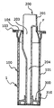
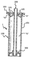
- Figure 1 is a longitudinal sectional view of the capsule device
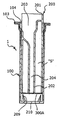
- Figure 2 shows the operating state of the operating part of the capsule device
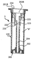
- Figure 3 is a longitudinal sectional view showing the capsule body of the capsule device
- Figure 4 is a longitudinal sectional view showing the operation of the capsule device
- FIG. 5 is a state in which the capsule device is assembled to the neck of the container, in particular, the longitudinal cross-sectional view showing a state in which the sprayer guide is inserted into the sprayer guide insert,
- Figure 6 shows a state in which the sprayer outlet is in the center, in particular the sprayer without the sprayer guide is coupled to the capsule device.
- FIG. 13 and 14 show an example of another modification of the capsule device of the present invention
- Figure 13 is a longitudinal cross-sectional view of the capsule
- FIG. 14 is a longitudinal sectional view showing a state in which the capsule is coupled to the container.
- 15 is a longitudinal sectional view showing yet another embodiment of a capsule.
- 16, 17, 18 is a longitudinal cross-sectional view illustrating that the basic structure of the capsule can be variously modified
- 19 is a longitudinal sectional view showing a state in which the capsule of the present invention is modified and applied differently.
- Figure 20 and 21 show another example of the capsule of the present invention
- Figure 20 is a longitudinal cross-sectional view of the capsule
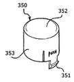
- 21 is a perspective view showing a protective cover.
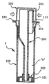
- FIG. 28 is a perspective view showing main parts of another example of the capsule of the present invention.
- 29 and 30 are longitudinal cross-sectional views showing another example of application of the capsule of the present invention.
- the capsule (1) having a circular frame 103 at the upper end to be caught by the container neck 500, and the capsule (1) is fixed to the container neck 500, and then pressed with a finger to open the storage space (S). Or, the storage space (S) is opened while the opening portion is pressed in the process of coupling the sprayer 400, the contents in the storage space (S) is dropped and mixed into the contents in the container 500, the mixing
- the contents are based on a capsule device configured to be sprayed through the final discharge device via the discharge unit 402 when the sprayer 400 is operated.
- the configuration of the spray guide insertion portion 104, the upper body portion 102 is more extended to the outside than the body portion 101 of the capsule body 100, the spray guide (to the extended space) 401 is configured to be located.
- Capsule (1) is composed of the body portion 101 and the upper body portion 102 and the capsule body 100 having a storage space (S) therein, the container neck 501 as the upper foreign exchange of the capsule body 100
- the ring frame 103 may be formed.
- the inner side of the annulus 103 constitutes a sprayer guide inserting portion 104, and the sprayer guide inserting portion 104 is formed to extend more than an inner wall of the body portion 101, and a sprayer guide ( 401 should be extended to a size that can be inserted, for this purpose, the upper end of the body portion 101 is very thin, or the thickness of the upper end portion 102 of the upper end portion of the body portion 101 to eventually thin
- the guide insertion wall 105 extended as thinned is formed.
- the spray guide 401 is inserted into the guide inserting wall 105 in close contact with or almost in contact, and the space to be inserted is called the spray guide inserting portion 104.
- the sealing body and operability capsule body In addition, in the coupling of the operating unit 200 around the storage space (S) of the capsule body 100, when the operating unit 200 is coupled to improve the coupling force, that is, the sealing body and operability capsule body
- the inner wall portion of the upper part of the body portion 101 of the 100 has a soft sealing wall 106 and an auxiliary sealing part 107, and the sealing wall 106 is connected to the annulus 103 by a part or more thereof. It can be applied as a technique to improve the sealing.
- the operating part 200 has a space extending from the top to the bottom, the lower portion of the space is a pipe portion 202, the upper portion of the operating load cylinder portion formed with the outer working sealing portion 206 for sealing ( 205 and the upper portion of the operating load cylindrical portion 205 is formed with a pressing portion 201.
- the inner portion of the operating load cylindrical portion 205 and the pipe portion 202 to form a space is configured to form the upper space 203 of the expanded form, and the lower space 204 of the collected form below. It can be.
- the operating unit 200 is coupled to the capsule body 100, and put the contents into the storage space (S) formed by being coupled to seal the lower end, as shown in the example, the pipe portion 202
- the sealing part 300 having the sealing surface 301 which is in close contact with the lower inner wall of the body part 101 is combined.
- the operating portion sealing portion 206 descends along the sealing wall 106, and the pipe portion 202 of the tube portion 202 is described in the above-described process.
- the sealing portion 300 coupled to the end is out of the body portion 101, the contents in the storage space (S) is dropped in the above process.
- Figure 3 shows the capsule body 100
- Figure 4 shows the operating unit 200, in particular it can be seen that the projections 207 protruding from the foreign exchange portion of the pipe 202, the jangdolgi 207 has the advantage of helping the long protrusion 207 to push the sealing portion 300 downward when the sealing portion 300 is composed only of a soft.
- FIG. 5 shows an example in which the sprayer 400 having the discharge part 402 is coupled to the side thereof, and in particular, the sprayer guide 401 is inserted into the sprayer guide inserting part 104. have.
- sprayer guide inserting part 104 into which the sprayer guide 401 of the protruding form can be inserted, so that the sprayer 400 can be easily encapsulated without being resisted by the capsule 1. It can be coupled to.
- discharge portion 402 is easily coupled through the expanded upper space 203 is coupled to the shape of the discharge portion 402 is partially modified along the lower space 204 of the lower collected form.
- operation part sealing part 206 is to maintain the sealing force in the upward direction while descending along the sealing wall 106.
- the capsule 1 may accommodate two or more sprayers 400 in one capsule 1 regardless of the positions of the discharge parts 402 and 402A.
- the ring-tight sealing part 108 is formed to protrude in one or both directions in the foreign exchange part of the ring frame 103, and the ring-tight sealing part 108 is preferably soft. Rubber material is good.
- the ring-tight sealing portion 108 serves to tightly close between the container neck 501 and the sprayer 400 when the capsule 1 is coupled to the container neck 501.
- the guide insertion wall 105 is shown to be thin, this is because the inner diameter of the existing container neck 501 is already determined that the guide insertion wall 105 should be as thin as possible within the limit, As shown in the figure is much thinner than the thickness of the body portion 101, depending on the situation, it is also possible to puncture at regular intervals so that the guide insertion wall 105 can be easily extended to resist the spray guides Do.
- the sealing wall 106A can be inserted or integrated between the upper inner wall portion of the trunk portion 101 and the guide insertion wall 105, in which case the capsule body 100 and The sealing wall 106A is formed to maintain the sealing property between the operating parts 200.
- the annulus 103A is extended to the foreign exchange unit, and the expanded foreign exchange unit end has a thickness and a material property in which the foreign exchange unit of the annulus 103A can be naturally folded in the process of combining the sprayer.
- thin is a good example.
- the spray guide is not seated on the guide insertion wall 105 and sometimes presses the annulus 103A, which is the upper end of the guide insertion wall 105, a part or more of the annulus 103A is not limited thereto.
- the bent capsule body 100 is to go down to the inside of the container neck.
- the foreign exchange part of the annulus 103A is intermittently split, combining the sprayer has the advantage that the foreign exchange portion of the annulus 103A can be easily bent and seated inside the sprayer.
- the guide insertion wall 105 is provided with a perforated portion 109, even if the specification of the spray guide is different, the guide insertion wall 105 is expandable to accommodate the spray guide.
- the storage space is opened while the opening is pressed, and the contents in the storage space are dropped and mixed with the contents in the container, and the mixed contents are discharged through the discharge unit when the sprayer is operated.
- the capsule device configured to be sprayed through.
- the annulus 103A constituting the capsule the upper portion of the body portion 100 of the capsule constituting the capsule becomes thin, when the sprayer is coupled to the sprayer guide is coupled while the thin portion is expanded.
- the upper portion of the body portion 101 is provided with a thin guide insertion wall 105A, the guide insertion wall 105A is made thin enough to be extended by the spray guide.
- annulus 103A is extended to the foreign exchange portion, the expanded portion of the foreign exchange portion having a thickness and material properties that can naturally be folded downward in the foreign exchange portion or the internal portion of the annulus 103A in the process of combining the sprayer will be.
- the capsule having a circular frame at the upper end to be caught by the container neck, and the capsule is fixed to the container neck and press the finger to open the storage space (S), or Alternatively, the storage space is opened while the opening portion is pressed in the process of combining the sprayer, the contents in the storage space are mixed drop by the contents in the container, and the mixed contents are discharged through the discharge part when the sprayer is operated.
- a capsule device configured to be dispensed through the device.
- the sprayer guide 401 in the process of the sprayer 400 is coupled to the upper end of the body portion 101 of the capsule 1 constituting the capsule (1) Press down the upper portion of the torso 101, and part of the annulus 103B is bent or stretched downward in the above process, the capsule 1 is coupled to move in a constant state inside the container neck 500 14 shows the above state.
- the annulus 103B may be made of a synthetic resin that can be made thinner or bent or elongated to extend or bend.
- the synthetic resin is made of rubber and is molded by a multi-injection molding machine.
- the foreign exchange unit 108B is formed at the foreign exchange unit of the annulus 103B.
- the foreign exchange portion of the annulus 103C is formed with a catching portion 110 capable of being caught by the foreign exchange portion of the container neck 500, so that even if the capsule 1 descends to the inside of the container neck.
- the catching part 110 is formed in the container neck bar to prevent the capsule (1) flowing into the container neck.
- the space 208 is formed long in the center direction in the operating unit 200 assembled into the interior of the capsule body 100, the configuration of such a space 208 and the operation unit 200 It is shown to illustrate that it can be variously modified.
- the configuration of the operation unit 200 and the capsule body 100 of the capsule 1 can be changed in various ways, as shown, the pressing portion ( 201) and the inner wall part of the capsule body 100 are shown to be connected as the folding part (F).
- the operating unit 200 having the storage space S is coupled to the inside of the capsule body 100 constituting the capsule 1, and the operating unit 200 extends from the upper side to the lower side. It forms a through space or constitutes a space composed of an upper space 203 and a lower space 204 around the tube part 202.
- the capsule body 100 when pressing the pressing portion 201 of the operating unit 200, the operating unit 200 is lowered inside the capsule body 100, the capsule body (in the above process)
- the perforated protrusion 209 formed at the bottom of the 100 breaks the sealed portion 300A, which seals the storage space S of the operating portion 200, and the contents of the storage space S in the above-described process.
- the drop mixing is performed via the drop space 210 formed around the perforation protrusion 209.
- the capsule 1 as shown in FIG. 18 may be used in combination with the inside of the container 500.
- reference numeral 211 denotes a pulling protrusion, which is used for drawing out the operation unit 200 after use, and thus the pulling protrusion 211 may be variously changed in design.
- the capsule body 100 when the capsule body 100 is coupled to the container neck 500, the capsule body 100 is used semi-permanently while replacing only the operating unit 200 without removing the capsule body 100 until the end of life.
- the locking groove 111 is provided at any one portion of the annulus 103 inward direction of the capsule body 100, and the protective cover protrusion of the protective cover 350 is disposed at the locking groove 111.
- 351 is to be coupled, and in the case of the above, when the side cover portion 353 having the protective cover protrusion 351 is pressed with a finger, the protective cover protrusion 351 is out of the locking groove 111, in the above state. After the protective cover 350 is removed, the pressing part 201 of the operating part 200 is pressed to open the sealing part 300.
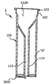
- the guide inserting wall 105 may be formed in various capsules 1, and as shown in FIG. 22, the storage space may be formed inside the capsule body 100.
- S the inside of the storage space (S) is the upper space 112 and the lower space 113 that can accommodate the sprayer ejection portion is formed, the lower portion is a sealed part for sealing the storage space (S) 300B is formed.
- the capsule 300 When the capsule 1 is used, the capsule 300 is removed and the capsule 1 is coupled so that the contents of the storage space S fall inside the container, and the sprayer discharge part is in the upper state. It is to be coupled through the space 112 and the lower space 113.
- FIG. 23 illustrates that the space 208 is applicable to the case where the space is located on one side
- FIG. 24 illustrates that the capsule body 100 may be separated and manufactured, and then combined.
- the discharge hole 115 is placed in the upper portion, and the contents are put through the discharge hole 115 and then the end portion thereof is shown to be finished with a pulling portion P, and when used, the pulling portion P is removed.
- the silver sprayer is based on a capsule device configured to be sprayed through the final dispensing device via an outlet upon operation.
- the spray guide is in the process of the sprayer is coupled to the upper end of the body portion 101 of the capsule body 100 constituting the capsule 1 body portion 101
- a spray guide inserting portion 104 containing a spray guide is formed on the inner side of the annulus 103D.
- the sprayer guide inserting portion 104 is formed in the form of the annulus 103D protrudes to the top of the sprayer guide inserting portion 104 is formed into a space, the annulus 104D is a soft synthetic resin Is a good example.
- the guide insertion wall 105 of the present invention may be applied to a technique in which the operation part 200 protrudes upward from the center portion. Further, the guide insertion wall 105 may be applied. Is a part or more of the perforated and the remaining portion may be in the form of connecting the upper frame 103 and the body portion 101 in the form of a connecting portion.
- the inclination angle of the guide insertion wall 105 can be freed, and the arbitrary positions of the guide insertion wall 105 are formed in the perforated part H of the form which perforated the hole, and the spray guide guide inserts it. It may be to help to expand the wall 105 easily.
- the guide insert walls 105 and 105' are formed between the annulus 103 and the sealing wall 106, so that the guides are formed in the process of forming the guide insertion walls 105 and 105 '.
- the guide insertion walls 105 and 105 are formed so as to separately meet the guide insertion wall 105 which is a soft rubber material and the relatively hard guide insertion wall 105'. ') Can be formed thin.
- the operation unit 200 has one or more upper insertion holes (212, 212 ') for accommodating the sprayer discharge portion, the lower portion of the operating unit 200 has a long extended cutting piece 213, The upper insertion holes 212 and 212 'are sealed by the pulling portion P.
- the cutting piece 213 cuts the cutting line 119 while the operating part 200 descends. Simultaneously with the pushing the cutting film 118, the contents of the storage space (S) in this process is to be mixed dropping into the container.
- the sprayer guide is to be coupled while being in close contact with or close to the guide insertion wall 105.
- the lower portion of the capsule body 100 constituting the capsule 1 is formed with a dropping space 117 and the perforation protrusion 116, the operation unit 200 is assembled into the interior of the capsule body 100 is Is a storage space (S), and the lower portion is composed of a closed portion (300C).
- the shape of the upper space 203A can be freely changed, and in detail, the guide and the seal or the discharge part (tube) or the discharge part guide of the sprayer, etc. It is shown that enough space is formed so that there is no problem in positioning.
- the capsule 1 is assembled to the container neck of the container, so that the parts inside the sprayer can be easily coupled through the lower space 204 and the upper space 203A of the capsule 1.
- the sealing part 300 coupled to the end of the pipe part 202 is opened.
- the capsule 1 is distributed in a state coupled to the inside of the container, and after the contents of the inside of the container are exhausted, the capsule 1 is taken out, and the inside of the container is filled with water. Combine capsule (1) around the container neck.
- the lower sealing unit 300 is opened and the contents contained in the storage space S are stored inside the container. It instantly transforms water into mixed contents.
- the capsule 1 of the present invention has an advantage of making new mixed contents immediately after using the contents of the container in a simple manner.
- the capsule (1) is lifted up and tilted around the inside of the container neck to combine the contents in the storage space (S) inside the container. It will be mixed with the water.
- the sprayer outlet (tube) is coupled through the lower space 113, and the protruding portion of the upper end to which the outlet is coupled is located in the upper space 112A.
- the sprayer will be combined.
- the modified capsule 1 of FIG. 34 is assembled to the container neck 501 of the container 500.
- the lower space 113 has a storage space ( It is located on the side of S), so that the sprayer outlet is located on the side is free to be coupled to the lower space 113, and in the case of the outlet is in the center, the outlet is bent sideways in the upper space (112A) While being bent into the lower space 113 is to be assembled.
- FIG. 36 an example of the modification of FIG. 33 is shown.
- the sealing part 300 In order to easily open the sealing part 300, the lower part of the upper part of the capsule body 100 is sealed, and the tube part 202 is elongated.
- the prefabricated pressing part 201B is coupled to the upper part of the pipe part 202 by means of pressing the upper part of the pipe part 202.
- the pull part made of soft resin has the sealing part 300C instead of the pull-tab type sealing part 300B shown in FIG. 34, and it protrudes in the bottom direction of the sealing part 300C in detail.
- the sealing portion 300C is separated from the bottom of the capsule body 100.
Landscapes
- Engineering & Computer Science (AREA)
- Mechanical Engineering (AREA)
- Containers And Packaging Bodies Having A Special Means To Remove Contents (AREA)
- Closures For Containers (AREA)
Abstract
용기목에 걸리도록 상단부에는 환테를 둔 캡슐과, 상기 캡슐은 용기목에 고정된 후 저장공간을 개방하는 부위를 손가락으로 압박하거나, 또는 스프레이어를 결합하는 과정에 개방하는 부위가 압박되면서 저장공간이 열리고, 상기 저장공간에 있는 내용물이 용기 내의 내용물에 낙하 혼합되고, 상기 혼합된 내용물은 스프레이어를 작동하면 배출부를 경유하여 최종 토출장치를 통해 분사되도록 구성된 캡슐장치와, 상기 캡슐을 구성하는 환테는, 캡슐을 구성하는 캡슐의 몸통부 상측인 몸통상단부의 내부 방향으로는 확장된 형태의 스프레이어가이드삽입부가 형성된 것을 특징으로한 스프레이어 가이드 삽입부가 있는 캡슐장치에 관한 것이다.
Description
본 발명은 방아쇠 분무기(트리거 스프레이어)가 장착된 용기와, 상기 용기내의 내용물을 사용한 후에 용기를 폐기하지 않고, 상기 용기 또는 빈용기에 물을 넣은 후 캡슐을 결합하여 즉석에서 이종물질을 혼합하여 사용하는 리필용 캡슐에 있어서, 상기 캡슐을 다양한 형태의 용기에 용이하게 결합하도록 구성한 스프레이어 가이드 삽입부가 있는 캡슐장치이다.
종래의 기술로서는, 미국특허 3,655,096/7,331,486/ 6,041,969/5,421,483/6,182,865/6,290,100 및 미국특허공개2007/228074 및 미국특허 5,957,335/6,152,326/5,529,216/5,836,479/8,302,816/8,261,943/4,201,316/ 6,997,351/7,874,420 및 본 발명인의 것으로서, PCT/KR2010/8175, PCT/KR2016/2097, PCT/KR2016/2098, PCT/KR2016/2739, PCT/KR2016/3752호가 있으며, 본 발명은 상기한 기술의 개량에 관한 것이다.
산업의 고도화, 또한 생활환경의 변화로 스프레이 용기(분무기)는 가정이나 산업용으로 널리 사용되고 있다. 이와 같이 널리 사용되는 분무기는 편리함과 더불어 이젠 환경 문제를 유발하는 등 심각한 지경에 이르렀다.
상기한, 분무기의 편리한 이면에 환경오염이란 문제가 있어, 분무기를 채용하여 유통하는 제조업체에서는 사용 후 용기를 폐기하지 않고 재사용할 수 있도록 리필용 제품을 장려하고 있다. 그러나 문제점으로는, 사용이 번거롭고 아직 대중화되지 못하여 구입이 어려운 문제도 발생하고 있다.
한편, 소비자의 경우, 리필용 제품을 사용하는 것 보다는 손쉬운 완제품을 사용하는 것이 가격은 다소 비싸도 편리함이 주는 만족도가 더 커 리필 문화는 아직 대중화되지 못하고 있다.
이상과 같은 분무기가 장착된 용기에 있어서, 상기 용기를 재사용할 수 있도록 기업 또는 개인을 불문하고 많은 분야에서 리필장치를 연구개발하고 있으며, 일예로 미국특허3,655,096/7,331,486의 경우는, 배출관의 뾰쪽한 단부를 통해 캡슐장치의 수용부를 개방하도록 구성한바, 일반적으로 유통되는 펌프장치의 배출관으로는 캡슐장치를 개방하는 것이 불가능한 폐단이 있었다.
그리고 미국특허6,041,969/5,421,483/6,182,865/6,290,100 및 미국특허공개2007/228074 및 미국특허 5,957,335의 경우는, 펌프장치를 용기목에 결합하는 과정에 캡슐장치의 수용부 하단 밀폐부가 절취되거나 분리되면서 열리도록 구성되어 있으나, 단점으로는, 펌프장치의 배출관이 중앙에 위치된 것만 수용가능하고, 펌프장치의 배출관이 중앙에서 벗어나 측방에 형성된 것의 경우는 적용이 불가능한 폐단이 있었다.
다른 유형으로서, 미국특허 6,152,326/5,529,216/5,836,479의 경우는, 캡슐장치의 수용부에 다수의 저장공간을 형성하고, 하나의 캡슐장치를 통해 적어도 2회 이상 리필이 가능하도록 구성한 특징이 있는 기술이다.
그러나 상기 기술의 문제점으로는, 보편적으로 유통되는 펌프장치를 통해서는 수용부의 저장공간을 개방하는 불가능하며, 따라서 별도의 보조수단을 부가하여 수용부의 저장공간을 개방하도록 구성한 폐단이 있었다.
또 다른 유형의 기술로서, 미국특허 8,302,816의 경우는, 캡슐장치의 저장공간에 이종물질을 충진하기 위한 충진부를 둔 특징이 있으며, 상기함에도 불구하고 펌프장치의 배출관이 중앙에 형성된 것만 수용 가능한 폐단이 있었다.
또 다른 유형의 것으로서, 미국특허 8,261,943의 경우는, 펌프장치의 배출관 구성 위치에 관계없이 캡슐장치에 펌프장치를 수용 가능하도록 캡슐장치에 배출관 결합공간을 보다 넓게 구성한 특징이 있는 기술이다.
그러나 문제점으로는, 펌프장치(또는 분무장치)의 밀폐부 및 튜브 등을 수용하는 공간이 설정되지 않은 폐단이 있어 다양한 종류의 분무장치를 수용하기 힘든 폐단이 있다.
또 다른 유형의 것으로서, 미국특허 4,201,316의 경우는, 펌프장치를 결합하면 캡슐장치가 결합되는 과정에 수용부의 하단부를 밀폐하는 밀폐부가 상부로 천공되고, 그 과정에 수용부의 저장공간에 든 이종물질이 용기 내부로 혼합되는 기술이다.
그러나 문제점으로는, 펌프장치의 배출관이 중앙에 위치된 것만 사용할 수 있는 폐단이 있었다.
또 다른 유형의 것으로서, 미국특허 6,997,351의 경우는, 캡슐장치를 회전시키는 과정에 내부에 설치된 수용부가 하방으로 내려가고, 상기한 과정에 수용부의 저장공간 하단부를 밀폐하는 밀폐부가 상부로 천공되면서 이종물질이 혼합되는 기술이다.
그러나 이 역시 펌프장치의 배출관이 중앙에 형성된 것만 사용할 수 있는 폐단이 있었다.
또 다른 유형의 것으로서, 미국특허7,874,420의 경우는, 캡슐장치의 상부면이 하부로 접철되면서 수용부의 저장공간이 열리도록 구성한 기술이다.
그러나 펌프장치의 배출관이 중앙에 형성된 것만 사용할 수 있는 폐단이 있었다.
또 다른 유형의 것으로서, 본 발명인의 PCT/KR2010/8175의 경우는, 캡슐장치의 수용부를 개방하기 위해 설치된 작동부가 필름 형태로 되어 있는바, 캡슐장치의 수용부를 개방하는 것이 매우 용이한 장점이 있지만, 문제점으로는 펌프장치의 배출관이 정 중앙에 있는 것만 적용이 가능한 폐단이 있었다.
그리고 본 발명의 또 다른 것으로서, PCT/KR2016/2097(도면 52,도면53,도면54), PCT/KR2016/2098(도면54, 도면 56), PCT/KR2016/2739(도면 8), PCT/KR2016/3752(도면 19)의 경우는, 펌프장치의 배출관 구성에 관계없이 사용할 수 있도록 캡슐이 설계되어 있다.
이상과 같은 종래 기술의 문제점으로는, 펌프장치의 배출관 구성 위치와 무관하게 리필용 캡슐장치를 적용할 수 있는 기술은 존재하지 않았으며, 따라서 본 발명은 상기한 종래 문제점을 극복하고, 더 하여는, 캡슐본체와 작동부로 구성된 리필용 캡슐의 작동 구조를 보다 명확히 하여 기능적으로 보다 개선된 리필용 캡슐을 제공하는 데에 그 목적이 있는 것이다.
그리고 종래의 기술은 배출관(이상 배출관이라고 함은 배출부 즉 튜브를 지칭하는 것임)이 중앙에 있는 것 위주로 개발되었고, 특히 미국특허 제8,261,943의 경우, 배출관이 측면에 있는 것의 경우도 수용할 수 있도록 배출관 삽입부를 구성하였으나, 상기 캡슐을 결합하여 사용할 수 있게 하려면 상기 캡슐은 용기의 내부에서 하부로 일정 깊이 내려가도록 구성해야만 사용할 수 있는바, 일반적인 용기에는 사용할 수 없는 폐단이 있었다.
본 발명은 이상의 문제점을 감안하여 종래의 용기의 개선 없이 일반적으로 사용되고 있는 용기에 본 발명의 캡슐장치를 적용할 수 있도록 하는 데에 그 목적이 있는 것이다.
또한 스프레이어가이드에 의해 캡슐의 상단부가 저항을 받아 기술적으로 캡슐을 사용할 수 없는 단점을 해결하기 위해 본 발명에서는 스프레이어가이드삽입부를 두어 스프레이어의 결합 형태에 무관하게 캡슐장치를 적용할 수 있도록 하는 데에 또 다른 목적이 있는 것이다.
용기목에 걸리도록 상단부에는 환테를 둔 캡슐과, 상기 캡슐은 용기목에 고정된 후 저장공간을 개방하는 부위를 손가락으로 압박하거나, 또는 스프레이어를 결합하는 과정에 개방하는 부위가 압박되면서 저장공간이 열리고, 상기 저장공간에 있는 내용물이 용기 내의 내용물에 낙하 혼합되고, 상기 혼합된 내용물은 스프레이어를 작동하면 배출부를 경유하여 최종 토출장치를 통해 분사되도록 구성된 캡슐장치를 기본으로 한다.
그리고 상기 캡슐을 구성하는 환테는, 캡슐을 구성하는 캡슐의 몸통부 상측인 몸통상단부의 내부 방향으로는 확장된 형태의 스프레이어가이드삽입부가 형성된 것이다.
또한 상기 스프레이어가이드삽입부의 구성은, 상기 캡슐의 몸통부 보다 몸통상단부가 외부로 더 확장된 상태이고, 상기 확장된 공간으로 스프레이어가이드가 위치될 수 있도록 구성한 것이다.
그리고 상기 스프레이어가이드삽입부의 구성은 몸통부와 몸통상단부로 구성된 캡슐의 상방부 내부 방향에 스프레이어가이드삽입부를 구성함에 있어, 상기 몸통부의 내부 벽보다 상기 몸통상단부의 내부 벽이 더 확장되게 하여 스프레이어 가이드가 삽입될 수 있는 스프레이어가이드삽입부를 구성한 것이다.
또한 상기 환테에는 환테밀폐부를 형성한 것이고, 더 하여는, 상기 환테는 외환부로 확장되고, 확장된 외환부 단부는 스프레이어를 결합하는 과정에 환테의 외환부가 자연스럽게 접힐 수 있는 두께 및 재질상의 물성을 갖는 것이다.
일 양상에 따르면, 용기목에 걸리도록 상단부에는 환테를 둔 캡슐과, 상기 캡슐은 용기목에 고정된 후 저장공간을 개방하는 부위를 손가락으로 압박하거나, 또는 스프레이어를 결합하는 과정에 개방하는 부위가 압박되면서 저장공간이 열리고, 상기 저장공간에 있는 내용물이 용기 내의 내용물에 낙하 혼합되고, 상기 혼합된 내용물은 스프레이어를 작동하면 배출부를 경유하여 최종 토출장치를 통해 분사되도록 구성된 캡슐장치를 기본으로 함과, 상기 캡슐을 구성하는 환테는, 캡슐을 구성하는 캡슐의 몸통부 상측이 얇게 되고, 스프레이어를 결합하면 얇은 부위가 확장되면서 스프레이어 가이드가 결합되는 것이다.
그리고 상기 환테는 외환부로 확장되고, 확장된 외환부 단부는 스프레이어를 결합하는 과정에 환테의 외환부 또는 내환부가 자연스럽게 하방으로 접힐 수 있는 두께 및 재질상의 물성을 갖는 것이다.
또 다른 양상에 따르면, 용기목에 걸리도록 상단부에는 환테를 둔 캡슐과, 상기 캡슐은 용기목에 고정된 후 저장공간을 개방하는 부위를 손가락으로 압박하거나, 또는 스프레이어를 결합하는 과정에 개방하는 부위가 압박되면서 저장공간이 열리고, 상기 저장공간에 있는 내용물이 용기 내의 내용물에 낙하 혼합되고, 상기 혼합된 내용물은 스프레이어를 작동하면 배출부를 경유하여 최종 토출장치를 통해 분사되도록 구성된 캡슐장치를 기본으로 함과, 상기 캡슐을 구성하는 환테는, 캡슐을 구성하는 캡슐의 몸통부 상단부를 스프레이어가결합되는 과정에 스프레이어 가이드가 몸통부 상단부를 압박하여 내려가게 하고, 상기한 과정에 환테의 일부가 하측으로 휘거나 또는 늘어나면서 캡슐이 용기목 내부로 일정 이동하는 상태로 결합되는 것이다.
그리고 상기 환테는 늘어나가나 휘어질 수 있도록 두께를 얇게 하거나, 또는 휘어지거나 늘어나는 것이 가능한 합성수지를 사용한 것이고, 상기 합성수지는 고무재질이며고, 다중사출성형기에 의해서 성형사출된 것이다.
또한 상기 환테의 외환부에는 환테밀폐부가 형성된 것이고, 상기 환테의 외환부에는 용기목의 외환부에 걸리는 것이 가능한 걸림부가 형성된 것이다.
또 다른 양상에 따르면, 용기목에 걸리도록 상단부에는 환테를 둔 캡슐과, 상기 캡슐은 용기목에 고정된 후 저장공간을 개방하는 부위를 손가락으로 압박하거나, 또는 스프레이어를 결합하는 과정에 개방하는 부위가 압박되면서 저장공간이 열리고, 상기 저장공간에 있는 내용물이 용기 내의 내용물에 낙하 혼합되고, 상기 혼합된 내용물은 스프레이어를 작동하면 배출부를 경유하여 최종 토출장치를 통해 분사되도록 구성된 캡슐장치를 기본으로 함과, 상기 캡슐을 구성하는 환테는, 캡슐을 구성하는 캡슐의 몸통부 상단부를 스프레이어가결합되는 과정에 스프레이어 가이드가 몸통부 상단부를 압박하여 캡슐이 내려가지 않도록 하기 위해 스프레이어 가이드를 수용하는 스프레이어가이드삽입부를 환테의 내측부 방향에 형성한 것이다.
그리고 상기 스프레이어가이드삽입부는 환테가 상부로 돌출된 형태로 되면서 내측이 공간으로 된 스프레이어가이드삽입부가 구성되는 것이고, 상기 환테는 연질의 합성수지인 것이다.
본 발명은 청소용품, 가든용품 등 산업이나 가정 등에서 광범위하게 사용될 수 있는 자세제어부를 갖는 리필용 캡슐이다.
리필전의 완제품은 매장의 진열 공간을 많이 확보하고, 또한 과 중량으로 유통비용이 과하게 지출되며, 또한 용기를 폐기하여 발생하는 환경오염이 심각하지만 본 발명의 캡슐장치는, 완제품의 1/5도 안 되는 부피로 매장의 진열 공간을 많이 차지하지 않음은 물론, 중량 또한 1/20 미만으로 매우 가벼워 유통비용이 현저하게 절감됨과, 또한 순환리필이 가능하여 쓰레기 공해를 줄일 수 있는 큰 특징이 있는 것이다.
다르게는, 사용방법이 간단하여 다양한 산업으로 진출하는 게 가능하고, 아울러 소비를 촉진하여 산업발전을 도모하는 순기능도 있다.
또한 스프레이어 가이드 삽입부가 있어 스프레이어 배출부가 측면부에 있는 스프레이어는 물론 스프레이어 가이드가 돌출된 형태의 스프레이어에도 본 발명의 캡슐을 적용할 수 있는 장점이 있다.
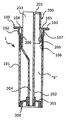
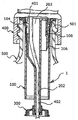
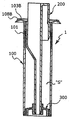
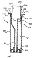
도 1 내지 도 6은 본 발명의 바람직한 일실시예를 보이고 있는 것으로서, 도 1 은 캡슐장치의 종단면도이고,
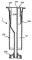
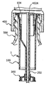
도 2 는 캡슐장치의 작동부가 작동된 상태를 보인 것이며,
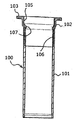
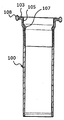
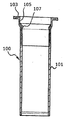
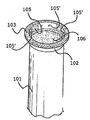
도 3 은 캡슐장치의 캡슐본체를 보인 종단면도이며,
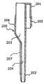
도 4 는 캡슐장치의 작동부를 보인 종단면도이며,
도 5 는 캡슐장치가 용기목에 조립된 상태를 보인 것으로서, 특히 스프레이어 가이드가 스프레이어가이드삽입부에 삽입된 상태를 보인 종단면도이며,
도 6 은 스프레이어 배출부가 중앙에 있고, 특히 스프레이어 가이드가 존재하지 않은 스프레이어가 캡슐장치에 결합된 상태를 보인 것이다.
도 7 내지 도 12 는 본 발명 캡슐장치인 작동부의 여러 변형의 예를 보인 것이다.
도 13 및 도 14 는 본 발명 캡슐장치의 또 다른 변형의 예를 보인 것으로서, 도 13 은 캡슐의 종단면도를 보인 것이고,
도 14 는 캡슐이 용기에 결합된 상태를 보인 종단면도이다.
도 15 는 캡슐의 또 다른 실시를 보인 종단면도이다.
도 16, 도 17, 도 18 은 캡슐의 기본구조가 다양하게 변형될 수 있음을 예시한 종단면도이고,
도 19 는 본 발명 캡슐이 또 다르게 변형되어 응용된 상태를 보인 종단면도이다.
도 20 및 도 21 은 본 발명 캡슐의 또 다른 변형의 예를 보인 것으로서, 도 20 은 캡슐의 종단면도이고,
도 21 은 보호덮개를 보인 사시도이다.
도 22, 도 23, 도 24, 도 25, 도 26, 도 27 은 는 본 발명인 캡슐의 또 다른 적용의 예를 보인 것이고,
도 28 은 본 발명 캡슐의 또 다른 적용의 예를 보인 요부 사시도이고,
도 29, 도 30 은 본 발명 캡슐의 또 다른 적용의 예를 보인 종단면도이다.
도 31 및 도 37은 본 발명의 또 다른 실시를 보인 것이다.
이하 도 1 내지 도 6을 참고하여 설명하면 다음과 같다.
용기목(500)에 걸리도록 상단부에는 환테(103)를 둔 캡슐(1)과, 상기 캡슐(1)은 용기목(500)에 고정된 후 저장공간(S)을 개방하는 부위를 손가락으로 압박하거나, 또는 스프레이어(400)를 결합하는 과정에 개방하는 부위가 압박되면서 저장공간(S)이 열리고, 상기 저장공간(S)에 있는 내용물이 용기(500) 내의 내용물에 낙하 혼합되며, 상기 혼합된 내용물은 스프레이어(400)를 작동하면 배출부(402)를 경유하여 최종 토출장치를 통해 분사되도록 구성된 캡슐장치를 기본으로 한다.
그리고 상기 캡슐(1)을 구성하는 환테(103)는, 캡슐(1)을 구성하는 캡슐본체(100)의 몸통부(101) 상측인 몸통상단부(102)의 내부 방향으로는 확장된 형태의 스프레이어가이드삽입부(104)가 형성된 것이다.
또한 상기 스프레이어가이드삽입부(104)의 구성은, 상기 캡슐본체(100)의 몸통부(101) 보다 몸통상단부(102)가 외부로 더 확장된 상태이고, 상기 확장된 공간으로 스프레이어가이드(401)가 위치될 수 있도록 구성한 것이다.
그리고 상기 스프레이어가이드삽입부(104)의 구성은 몸통부(101)와 몸통상단부(102)로 구성된 캡슐(1)의 상방부 내부 방향에 스프레이어가이드삽입부(104)를 구성함에 있어, 상기 몸통부(101)의 내부 벽보다 상기 몸통상단부(102)의 내부 벽이 더 확장되게 하여 스프레이어가이드(401)가 삽입될 수 있는 스프레이어가이드삽입부(104)를 구성한 것이다.
이와 같은 본 발명의 캡슐(1)의 스프레이어가이드삽입부(104)가 적용될 수 있는 일예를 도면을 참고하여 설명하고자 한다.(도 1 및 도 2 또는 도 5 및 도 6 참고)
캡슐(1)은 몸통부(101)와 몸통상단부(102) 그리고 내부로 저장공간(S)이 있는 캡슐본체(100)로 구성되고, 상기 캡슐본체(100)의 상단 외환으로 용기목(501)에 걸릴 수 있는 환테(103)가 형성된다.
그리고 상기 환테(103)의 내측 방향에는 스프레이어가이드삽입부(104)를 구성하며, 상기 스프레이어가이드삽입부(104)는 몸통부(101)의 내벽보다 더 확장된 형태이고, 스프레이어가이드(401)가 삽입 될 수 있을 정도의 규격으로 확장되어야 하며, 이를 위해서는 몸통부(101)의 상단부가 아주 얇거나, 또는 몸통부(101)의 상단부에 있는 몸통상단부(102)의 두께를 얇게 하여 결국 얇아진 만큼 확장된 가이드삽입벽(105)이 형성되는 것이다.
즉, 가이드삽입벽(105)에 스프레이어가이드(401)가 밀착 또는 거의 닿는 형태로 삽이되며, 이런 삽입되는 공간을 스프레이어가이드삽입부(104)라 칭한 것이다.
또한 상기 캡슐본체(100)의 저장공간(S)을 중심으로는 작동부(200)를 결합함에 있어, 상기 작동부(200)가 결합될 때에 결합력 즉, 밀폐성과 작동성을 향상시키기 위해 캡슐본체(100)의 몸통부(101) 상부 측 내벽부에는 연질의 밀폐벽(106)과 보조밀폐부(107)를 둔 것이며, 상기 밀폐벽(106)은 일부 이상이 연결되어 환테(103)까지 연결되어 밀폐성을 향상시키는 기술로 적용될 수 있는 것이다.
그리고 작동부(200)는 상부에서 하부로 길게 연장된 공간이 있고, 상기 공간의 하부는 관부(202)가 있으며, 상부는 밀폐용 작동부밀폐부(206)가 외한부로 형성된 작동부하원통부(205)가 있음과, 상기 작동부하원통부(205)의 상방부에는 압박부(201)가 형성된 것이다.
또한 상기 작동부하원통부(205) 및 관부(202)의 내측에는 공간을 구성함에 있어, 상방부는 확장된 형태의 상부공간(203)을, 그리고 하방에는 모아진 형태의 하부공간(204)을 구성할 수 있는 것이다.
그리고 상기 캡슐본체(100)에 작동부(200)가 결합되고, 결합됨으로 인해 형성된 저장공간(S)에는 내용물을 넣고 그 하단부를 밀폐시키는데, 그 일예를 보이면 도시한 바와 같이, 관부(202)를 기준으로 하여 몸통부(101)의 하단 내벽부를 밀착시키는 밀폐면(301)이 있는 밀폐부(300)를 결합한 것이다.
이와 같은 캡슐(1)에 있어서, 작동부(200)의 압박부(201)를 압박하면 작동부밀폐부(206)가 밀폐벽(106)을 따라 내려가고, 상기한 과정에 관부(202)의 단부에 결합된 밀폐부(300)가 몸통부(101)를 벗어나며, 상기한 과정에 저장공간(S)에 있던 내용물이 낙하되는 것이다.
도 3 은 캡슐본체(100)를 보인 것이고, 도 4 는 작동부(200)를 보인 것이며, 특히 관부(202)의 외환부에 돌출된 장돌기(207)를 둔 것을 알 수 있으며, 상기 장돌기(207)는 밀폐부(300)가 연질로만 구성될 경우 장돌기(207)가 밀폐부(300)를 하부로 밀어 내는 역할을 돕는 장점이 있다.
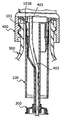
도 5 의 경우는, 배출부(402)가 측면에 있는 스프레이어(400)가 결합된 일예를 보이고 있으며, 특히 스프레이어가이드(401)가 스프레이어가이드삽입부(104)에 삽입된 상태를 보이고 있다.
이와 같이 돌출된 형태의 스프레이어가이드(401)가 삽입될 수 있는 스프레이어가이드삽입부(104)가 있는바, 캡슐(1)에 저항을 받지 않고 스프레이어(400)가 용이하게 캡슐(1)에 결합될 수 있는 것이다.
그리고 배출부(402)는 확장된 형태의 상부공간(203)을 통해 용이하게 결합되다가 하측의 모아진 형태의 하부공간(204)을 따라 배출부(402)의 형상이 일부 변형되면서 결합되는 것이다.
또한 작동부밀폐부(206)는 밀폐벽(106)을 따라 내려가면서 상측 방향으로는 지속적으로 밀폐력을 유지하는 것이다.
도 5 는 배출부(402A)가 중앙에 있는 스프레이어(400)가 용기(500)에 결합된 상태를 보이고 있으며, 이 경우는 스프레이어(400)가 캡슐(1)에 별다른 저항을 주지 않으면서 용이하게 결합된다.
따라서 상기 캡슐(1)은 배출부(402, 402A)의 위치에 관계없이 하나의 캡슐(1)로 두 가지 이상의 스프레이어(400)를 수용할 수 있는 것이다.
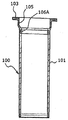
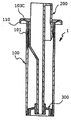
도 7 의 경우는, 환테(103)의 외환부로 상하 또는 어느 일 방향으로 돌출된 형태의 환테밀폐부(108)를 형성한 것이며, 상기 환테밀폐부(108)는 연질인 것이 좋으며, 바람직하게는 고무재질이 좋다.
그리고 상기 환테밀폐부(108)는 캡슐(1)이 용기목(501)에 결합될 때 용기목(501)과 스프레이어(400) 사이를 긴밀하게 밀폐시키는 역할을 한다.
도 8 의 경우는, 가이드삽입벽(105)이 얇게 된 것을 보이고 있으며, 이런 이유는 기존 용기목(501)의 내경이 이미 정해져 있기 때문에 가이드삽입벽(105)은 한계치 이내로 최대한 얇게 해야만 하는 것이며, 도시한 바와 같이 몸통부(101)의 두께 보다 훨씬 더 얇게 된 것이고, 상황에 따라서는, 상기 가이드삽입벽(105)이 스프레이어가이드에 저항을 받아 쉽게 확장될 수 있도록 일정 간격으로 천공시키는 것도 가능하다.
도 9 의 경우는, 몸통부(101)의 상단 내벽부와 가이드삽입벽(105)의 사이에는 밀폐벽(106A)을 끼우거나 일체로 할 수 있음을 보인 것이며, 이 경우 캡슐본체(100)와 작동부(200) 사이의 밀폐성 유지를 위해 밀폐벽(106A)이 형성되는 것이다.
도 10 의 경우는, 환테(103A)는 외환부로 확장되고, 확장된 외환부 단부는 스프레이어를 결합하는 과정에 환테(103A)의 외환부가 자연스럽게 접힐 수 있는 두께 및 재질상의 물성을 갖는 것이며, 바람직하게는, 얇은 것이 좋은 예이다.
참고적으로, 스프레이어가이드가 가이드삽입벽(105)에 안착되지 못하고 경우에 따라 가이드삽입벽(105)의 상단인 환테(103A)를 압박할지라도 이에 구애됨이 없이 환테(103A)의 일부 이상이 휘면서 캡슐본체(100)가 용기목 내부로 일정 내려가게 되는 것이다.
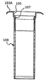
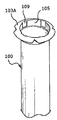
도 11 의 경우는, 환테(103A)의 외환부가 간헐적으로 갈라져 있는바, 스프레이어를 결합하면 환테(103A)의 외환부가 쉽게 휘면서 스프레이어 내부로 안착될 수 있는 장점이 있다.
그리고 가이드삽입벽(105)에는 천공부(109)를 둔바 스프레이어가이드의 규격에 차이가 날지라도 가이드삽입벽(105)이 확장 가능하여 스프레이어가이드를 수용할 수 있는 것이다.
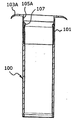
다른 실시로서(도 12를 일부 참고하여), 용기목에 걸리도록 상단부에는 환테(103A)를 둔 캡슐과, 상기 캡슐은 용기목에 고정된 후 저장공간을 개방하는 부위를 손가락으로 압박하거나, 또는 스프레이어를 결합하는 과정에 개방하는 부위가 압박되면서 저장공간이 열리고, 상기 저장공간에 있는 내용물이 용기 내의 내용물에 낙하 혼합되고, 상기 혼합된 내용물은 스프레이어를 작동하면 배출부를 경유하여 최종 토출장치를 통해 분사되도록 구성된 캡슐장치를 기본으로 한다.
그리고 상기 캡슐을 구성하는 환테(103A)는, 캡슐을 구성하는 캡슐의 몸통부(100) 상측이 얇게 되고, 스프레이어를 결합하면 얇은 부위가 확장되면서 스프레이어 가이드가 결합되는 것이다.
또한 상기 몸통부(101)의 상측에 얇은 형태의 가이드삽입벽(105A)를 둔 것이며, 상기한 가이드삽입벽(105A)은 스프레이어가이드에 의해서 확장될 수 있을 정도의 얇은 두께로 한다.
그리고 상기 환테(103A)는 외환부로 확장되고, 확장된 외환부 단부는 스프레이어를 결합하는 과정에 환테(103A)의 외환부 또는 내환부가 자연스럽게 하방으로 접힐 수 있는 두께 및 재질상의 물성을 갖게 하는 것이다.
또 다른 실시예로서(도 13 및 14 참고), 용기목에 걸리도록 상단부에는 환테를 둔 캡슐과, 상기 캡슐은 용기목에 고정된 후 저장공간(S)을 개방하는 부위를 손가락으로 압박하거나, 또는 스프레이어를 결합하는 과정에 개방하는 부위가 압박되면서 저장공간이 열리고, 상기 저장공간에 있는 내용물이 용기 내의 내용물에 낙하 혼합되고, 상기 혼합된 내용물은 스프레이어를 작동하면 배출부를 경유하여 최종 토출장치를 통해 분사되도록 구성된 캡슐장치를 기본으로 한다.
그리고 상기 캡슐(1)을 구성하는 환테(103B)는, 캡슐(1)을 구성하는 캡슐(1)의 몸통부(101) 상단부를 스프레이어(400)가 결합되는 과정에 스프레이어가이드(401)가 몸통부(101) 상단부를 압박하여 내려가게 하고, 상기한 과정에 환테(103B)의 일부가 하측으로 휘거나 또는 늘어나면서 캡슐(1)이 용기목(500) 내부로 일정 이동하는 상태로 결합되는 것이며, 상기한 상태를 보인 것이 도 14 와 같다.
또한 상기 환테(103B)는 늘어나가나 휘어질 수 있도록 두께를 얇게 하거나, 또는 휘어지거나 늘어나는 것이 가능한 합성수지를 사용할 수 있으며, 상기 합성수지는 고무재질이고, 다중사출성형기에 의해서 성형사출된 것이다.
그리고 상기 환테(103B)의 외환부에는 환테밀폐부(108B)가 형성된 것이다.
다르게는(도 15 참고), 환테(103C)의 외환부에는 용기목(500)의 외환부에 걸리는 것이 가능한 걸림부(110)가 형성된 것이며, 따라서 캡슐(1)이 용기목 내부로 일정 내려갈지라도 걸림부(110)가 용기목에 결려지는바 캡슐(1)이 용기목 내부로 흘러들어가는 것을 예방할 수 있는 것이다.
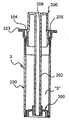
도 16 의 경우는, 캡슐본체(100)의 내부로 조립되는 작동부(200)에 중앙방향에 길게 공간(208)이 형성된 것을 보이고 있으며, 이러한 공간(208) 및 작동부(200)의 구성은 다양하게 변형될 수 있음을 예시하기 위해 도시한 것이다.
상기한 것의 사용 시에는, 도 16 과 같은 상태에서 작동부(200)를 압박하면 작동부하원통부(205)가 하향되고, 동시에 관부(202)의 하방에 결합된 밀폐부(300)가 열리면서 저장공간(S)에 있던 내용물이 낙하 혼합되는 것이다.
그리고 스프레이어 배출부는 중앙에 형성된 공간(208)을 통해 결합하게 된다.
도 17 의 경우는, 본 발명의 예시도, 캡슐(1)의 작동부(200) 및 캡슐본체(100)의 구성이 다양하게 변경될 수 있음을 예시한 것으로서, 도시한 바와 같이, 압박부(201)와 캡슐본체(100)의 내벽부 사이를 접철부(F)로서 연결시킨 것을 나타내 보이고 있다.
그리고 상기한 캡슐(1)의 사용 시에는, 존재할 경우, 먼저 보조밀폐부(310)를 제거하고, 압박부(201)를 압박하면 접철부(F)가 접철됨과 동시 작동부(200)의 하방에 있는 밀폐부(300)가 열리는 것이며, 상기한 상태에서 스프레이어 배출부를 상부공간(203)과 하부공간(204)을 통해 들어가도록 결합하는 것이다.
도 18 의 경우는, 캡슐(1)을 구성하는 캡슐본체(100)의 내부에 저장공간(S)이 있는 작동부(200)를 결합하고, 상기 작동부(200)에는 상부에서 하부로 길게 연장 관통된 공간을 형성하거나, 또는 관부(202)를 중심으로 내부에 상부공간(203)과 하부공간(204)으로 구성된 공간을 구성한 것이다.
그리고 상기한 캡슐(1)의 사용 시에는, 작동부(200)의 압박부(201)를 압박하면 캡슐본체(100)의 내부에서 작동부(200)가 내려가고, 상기한 과정에 캡슐본체(100)의 저부에 형성된 천공돌기(209)에 의해 작동부(200)의 저장공간(S)을 밀폐하고 있는 밀폐부(300A)가 파괴되며, 상기한 과정에 저장공간(S)에 있던 내용물이 천공돌기(209)의 주위에 형성된 낙하공간(210)을 경유하여 낙하 혼합되는 것이다.
또한 상기한 상태에서, 스프레이어 배출부를 상부공간(203)을 통해 결합하면 배출부는 하부공간(204)을 통해 용기 내부로 길게 삽입되게 된다.
도 19 의 경우는, 도 18 과 같은 캡슐(1)이 용기(500)의 내부에 결합되어 사용될 수 있음을 예시한 것이다.
도면 중 미설명 부호 (211)은 당김돌기를 표시한 것으로서 사용후 작동부(200)를 인출하는 용도로 사용되는 것이며, 따라서 당김돌기(211)는 다양하게 설계 변경될 수 있는 것이다.
참고적으로, 캡슐본체(100)는 용기목(500)에 결합되면 수명이 다할 때 까지 캡슐본체(100)는 분리하지 않고 작동부(200)만 교체하면서 반영구적으로 사용하는 것이다.
도 20 및 도 21 의 경우는, 캡슐본체(100)의 환테(103) 내측 방향의 임의 일 부위에 걸림홈(111)을 두고, 상기 걸림홈(111)에는 보호덮개(350)의 보호덮개돌기(351)가 결합되도록 한 것이며, 상기한 것의 경우, 보호덮개돌기(351)가 있는 측면부(353)를 손가락으로 압박하면 보호덮개돌기(351)가 걸림홈(111)을 벗어나고, 상기한 상태에서 보호덮개(350)를 제거한 후에 작동부(200)의 압박부(201)를 압박하면 밀폐부(300)가 열리게 되는 것이다.
그리고 상기 보호덮개(350)의 상면부(352) 및 측면부(353)가 작동부(200)를 보호하고 있어 어린아이들이 캡슐(1)을 임의로 사용할 수 없는 장점이 있다.
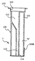
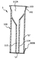
도 22, 도 23, 도 24 의 경우는, 다양한 캡슐(1)에 가이드삽입벽(105)이 형성될 수 있음을 예시한 것으로서, 더시한 바와 같이, 캡슐본체(100)의 내부에 저장공간(S)이 있고, 상기한 저장공간(S)의 내부에는 스프레이어 베출부를 수용가능한 상부공간(112) 및 하부공간(113)이 형성되어 있는 것이며, 하부는 저장공간(S)을 밀폐하는 밀폐부(300B)가 형성되어 있는 것이다.
그리고 상기한 캡슐(1)의 사용 시에는, 밀폐부(300B)를 제거하고 저장공간(S)의 내용물이 용기 내부에 낙하되도록 캡슐(1)을 결합하고, 상기한 상태에서 스프레이어 배출부가 상부공간(112) 및 하부공간(113)을 통해 결합되도록 한 것이다.
특히 도 23 의 경우는, 공간(208)이 일측부에 있는 것의 경우에도 적용 가능함을 예시한 것이고, 도 24 의 경우는, 캡슐본체(100)를 분리하여 제작한 후 결합할 수 있음도 예시한 것이며, 이 경우 상부에 배출공(115)을 두고, 상기 배출공(115)을 통해 내용물을 넣은 후 그 단부를 당김부(P)로 마감한 것을 보이며, 사용 시에는 당김부(P)를 제거 한 후에 저장공간(S)에 든 내용물을 용기 내부에 혼합한 후에 캡슐(1)을 용기에 결합하여 사용하는 것이다.
또 다른 실시로서(도 25 참고), 용기목에 걸리도록 상단부에는 환테(103D)를 둔 캡슐(1)과, 상기 캡슐(1)은 용기목에 고정된 후 저장공간(S)을 개방하는 부위를 손가락으로 압박하거나, 또는 스프레이어를 결합하는 과정에 개방하는 부위가 압박되면서 저장공간(S)이 열리고, 상기 저장공간(S)에 있는 내용물이 용기 내의 내용물에 낙하 혼합되며, 상기 혼합된 내용물은 스프레이어를 작동하면 배출부를 경유하여 최종 토출장치를 통해 분사되도록 구성된 캡슐장치를 기본으로 한다.
그리고 상기 캡슐(1)을 구성하는 환테(103D)는, 캡슐(1)을 구성하는 캡슐본체(100)의 몸통부(101) 상단부를 스프레이어가 결합되는 과정에 스프레이어가이드가 몸통부(101) 상단부를 압박하여 캡슐(1)이 내려가지 않도록 하기 위해 스프레이어가이드를 수용하는 스프레이어가이드삽입부(104)를 환테(103D)의 내측부 방향에 형성한 것이다.
또한 상기 스프레이어가이드삽입부(104)는 환테(103D)가 상부로 돌출된 형태로 되면서 내측이 공간으로 된 스프레이어가이드삽입부(104)가 구성되는 것이며, 상기 환테(104D)는 연질의 합성수지인 것이 좋은 예이다.
참고적으로, 상기 도 25과 같은 상태에서(캡슐(1)이 용기목에 결합되었다는 과정 하에), 작동부(200)를 압박하면 작동부(200)의 하방에 결합된 밀폐부(300)가 열리면서 저장공간(S)의 내용물이 낙하되는 것이며, 상기한 상태에서 스프레이어를 결합하면 스프레이어가이드가 스프레이어가이드삽입부에 위치되고, 상기한 상태에서 캡슐(1)은 더 이상 내려가지 않고 멈추게 되는 것이다.
도 26 의 경우는, 작동부(200)가 중앙부에서 상부로 일부 돌출된 기술에도 본 발명의 가이드삽입벽(105)이 적용될 수 있음을 예시한 것이며, 좀 더 보충하면, 가이드삽입벽(105)은 일부 이상의 면이 천공되고 나머지 부분이 연결부 형태로 환테(103)와 몸통부(101) 상단부를 연결시키는 형태로 될 수 있는 것이다.
도 27 의 경우는, 가이드삽입벽(105)의 경사각을 자유롭게 할 수 있고, 또한 가이드삽입벽(105)의 임의 부위에는 구멍이 뚫린 형태의 천공부위(H)를 형성하여 스프레이어가이드가 가이드삽입벽(105)을 용이하게 확장시키는 것을 돕게 할 수 있는 것이다.
도 28 의 경우는, 가이드삽입벽(105,105')을 형성함에 있어, 환테(103)와 밀폐벽(106)의 사이에 가이드삽입벽(105,105')이 형성되는 과정에 두 재질이 만남으로 인해 가이드삽입벽(105,105')의 두께가 두꺼워지는 것을 방지하기 위해 연질의 고무재질인 가이드삽입벽(105)과 비교적 경질의 가이드삽입벽(105')을 별도 분리하여 만나도록 설계한바 가이드삽입벽(105,105')을 얇게 형성할 수 있는 것이다.
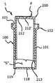
도 29 의 경우는, 가이드삽입벽(105)이 있고, 상기한 가이드삽입벽(105)이 있는 몸통부(101)의 하방에는 절취선(119)으로 구획된 절취막(118)이 있으며, 상기 몸통부(101)의 내부에는 저장공간(S)이 있는 캡슐본체(100)의 내부로는 작동부(200)를 조립시킨다.
그리고 상기 작동부(200)는 스프레이어 배출부를 수용할 수 있는 상부삽입공(212,212')을 하나 이상 두며, 상기 작동부(200)의 하부로는 길게 연장된 절취편(213)을 둔것이고, 상기 상부삽입공(212,212')은 당김부(P)에 의해서 밀폐되어 있다.
이와 같이 된 캡슐(1)의 사용 시에는, 캡슐(1)을 용기목에 결합하고 작동부(200)를 압박하면 작동부(200)가 내려가면서 절취편(213)이 절취선(119)을 절취함과 동시 절취막(118)을 밀어 내게 되며, 이 과정에 저장공간(S)에 든 내용물이 용기 내부로 낙하 혼합되는 것이다.
또한 상기한 과정에, 당김부(P)를 당겨 상부삽입공(212,212')이 노출되게 한 후 스프레이어 배출부의 위치에 따라 상기 상부삽입공(212,212')에 집어 넣은 후 스프레이어를 결합하여 사용하는 것이며, 이때에 스프레이어 가이드는 상기 가이드삽입벽(105)에 밀착되거나 또는 근접하게 위치되면서 결합되게 되는 것이다.
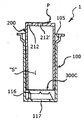
도 30 의 경우는, 도 29와 작동 및 사용은 동일하지만, 다만 저장공간(S)의 개방형태만 약간 상이하며, 여기서는 캡슐(1)의 상이한 부분만 설명하고자 한다.
상기 캡슐(1)을 구성하는 캡슐본체(100)의 하부는 낙하공간(117)과 천공돌기(116)가 형성되어 있으며, 상기 캡슐본체(100)의 내부로 조립되는 작동부(200)는 내부가 저장공간(S)으로 되어 있고, 하부는 밀폐부(300C)로 구성되어 있다.
그리고 상기한 캡슐(1)의 사용 시에는, 작동부(200)를 압박하면 작동부(200)가 하강하면서 밀폐부(300C)가 천공돌기(116)에 닿아 절취되고, 이와 동시에 저장공간(S)에 있던 내용물이 낙하공간(117)을 경유 낙하하게 되는 것이다. 기타 다른 부분은 도 29와 유사하다.
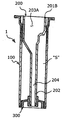
도 31 및 도 32 도 33 의 경우는, 상부공간(203A)의 형태는 자유롭게 변경될 수 있음을 보인 것으로서, 상세하게는, 스프레이어의 가이드 및 밀폐부 또는 배출부(튜브) 또는 배출부 가이드 등이 위치하여 자리 잡는 데에 지장이 없도록 충분한 공간이 형성되게 한 것을 보인 것이다.
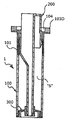
특히 도 33 의 경우는, 캡슐(1)이 용기의 용기목에 조립되고, 상기 캡슐(1)의 하부공간(204) 및 상부공간(203A)을 통해 스프레이어 내부 부품 들이 용이하게 결합될 수 있도록 한 것을 보인 것이고, 사용 시에는, 압박부(201B)를 별도의 도구로 밀게 되면 관부(202)의 단부에 결합된 밀폐부(300)가 열리게 구성한 것이다.
참고적으로, 본 캡슐(1)는 용기의 내부에 결합된 상태로 유통되는 바, 용기 내부의 내용물을 다 사용하고 난 후에 캡슐(1)을 꺼내고, 용기 내부에 물을 채우며, 그 후에 용기의 용기목을 중심으로 캡슐(1)을 결합한다.
그리고 상기한 상태에서 압박부(201B) 또는 작동부(200)의 임의 일 부위를 별도의 도구로 밀게 되면 하방의 밀폐부(300)가 열림과 동시에 저장공간(S)에 든 내용물이 용기 내부의 물을 순간적으로 혼합 내용물로 변형시키는 것이다.
이와 같이 본 발명의 캡슐(1)은 간편한 방법으로 용기의 내용물을 다 사용하고 난 후 즉석에서 새로운 혼합 내용물을 만들 수 있는 장점이 있는 것이다.
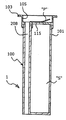
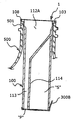
도 34 의 경우는, 용기 내부에 내용물이 들어 있는 상태에서, 용기목을 중심으로 캡슐(1)을 결합하는 데에 중점을 둔 것으로서, 사용 시에는 용기 내부의 내용물을 다 사용하고 난 후에 캡슐(1)의 저장공간(S)에 든 내용물을 용기 내부에 재충전된 물과 혼합하여 사용하도록 구성된 기술이다.
상세하게는, 밀폐부(300B)를 당겨 저장공간(S)을 개방한 후에 캡슐(1)을 치겨들고 용기목의 내부를 중심으로 기울여 결합하게 되면 저장공간(S)에 든 내용물이 용기 내부에 든 물과 혼합되게 되는 것이다.
상기한 상태에서 스프레이어를 용기목을 중심으로 결합하면, 스프레이어 배출대(튜브)는 하부공간(113)을 통해 결합되고, 배출대가 결합되는 상단부의 돌출된 부위는 상부공간(112A)에 위치되면서 스프레이어가 결합되게 되는 것이다.
도 35 의 경우는, 도 34 의 변형된 캡슐(1)이 용기(500)의 용기목(501)에 조립된 상태를 보인 것으로서, 도 34 와 다른 점은, 하부공간(113)이 저장공간(S)의 측방에 위치된 것이며, 따라서 스프레이어 배출대가 측방에 위치된 것은 하부공간(113)에 결합되는 것이 자유롭고, 배출대가 중앙에 있는 것의 경우는, 상부공간(112A)에서 배출대가 측방으로 휘면서 하부공간(113)으로 휘어지며 조립되게 되는 것이다.
도면 34 및 35 중에서 부호표시 "P는 스프레이어 배출대가 용이하게 결합될 수 있도록 천공부를 형성한 것을 보인 것이다.
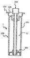
도 36 의 경우는, 도 33 의 변형의 예를 보인 것으로서, 밀폐부(300)를 용이하게 개방하기 위해 캡슐본체(100)의 상방 내부를 밀폐시킨 하부로는 길게 연장된 관부(202)를 두고, 상기 관부(202)의 저부에 밀폐부(300)를 둔 것에 있어서, 상기 관부(202) 상방부를 압박하는 수단으로 조립식 압박부(201B)를 관부(202)의 상부를 중심으로 결합시킨 것이다.
이와 같은 것의 사용 시에는, 압박부(201B)를 당기면 결합용공간(220)에 있던 압박용돌출부(222)가 상합되며, 상기한 과정에 압박부(201B)를 일부 회전시키면 압박용돌출부(222) 단부가 턱부(221)에 위치되게 되고, 상기한 상태에서 압박부(201B)를 압박하면 관부(202)가 내려가면서 밀폐부(300)가 열리게 되는 것이다.
도 37 의 경우는, 도 34에서 도시한 풀탭 방식의 밀폐부(300B)대신 연질의 수지로 된 당김부가 밀폐부(300C)를 둔 것이며, 상세하게는, 밀폐부(300C)의 저부 방향에 돌출된 당김부를 두고, 사용 시에는 상기 당김부를 잡아 당기면 밀폐부(300C)가 캡슐본체(100)의 저부로 이탈되는 것이다.
Claims (15)
- 용기목에 걸리도록 상단부에는 환테를 둔 캡슐과, 상기 캡슐은 용기목에 고정된 후저장공간을 개방하는 부위를 손가락으로 압박하거나, 또는 스프레이어를 결합하는 과정에 개방하는 부위가 압박되면서 저장공간이 열리고, 상기 저장공간에 있는 내용물이 용기 내의 내용물에 낙하 혼합되고, 상기 혼합된 내용물은 스프레이어를 작동하면 배출부를 경유하여 최종 토출장치를 통해 분사되도록 구성된 캡슐장치에 있어서,상기 캡슐을 구성하는 환테는, 캡슐을 구성하는 캡슐의 몸통부 상측인 몸통상단부의 내부 방향으로는 확장된 형태의 스프레이어가이드삽입부가 형성된 것을 특징으로한 스프레이어 가이드 삽입부가 있는 캡슐장치.
- 제 1 항에 있어서, 상기 스프레이어가이드삽입부의 구성은, 상기 캡슐의 몸통부 보다 몸통상단부가 외부로 더 확장된 상태이고, 상기 확장된 공간으로 스프레이어가이드가 위치될 수 있도록 구성한 것을 특징으로한 스프레이어 가이드 삽입부가 있는 캡슐장치.
- 제 1 항에 있어서, 상기 스프레이어가이드삽입부의 구성은 몸통부와 몸통상단부로 구성된 캡슐의 상방부 내부 방향에 스프레이어가이드삽입부를 구성함에 있어, 상기 몸통부의 내부 벽보다 상기 몸통상단부의 내부 벽이 더 확장되게 하여 스프레이어 가이드가 삽입될 수 있는 스프레이어가이드삽입부를 구성한 것을 특징으로한 스프레이어 가이드 삽입부가 있는 캡슐장치.
- 제 1 항에 있어서, 상기 환테에는 환테밀폐부를 형성한 것을 특징으로한 스프레이어 가이드 삽입부가 있는 캡슐장치.
- 제 1 항에 있어서, 상기 환테는 외환부로 확장되고, 확장된 외환부 단부는 스프레이어를 결합하는 과정에 환테의 외환부가 자연스럽게 접힐 수 있는 두께 및 재질상의 물성을 갖는 것을 특징으로한 스프레이어 가이드 삽입부가 있는 캡슐장치.
- 용기목에 걸리도록 상단부에는 환테를 둔 캡슐과, 상기 캡슐은 용기목에 고정된 후저장공간을 개방하는 부위를 손가락으로 압박하거나, 또는 스프레이어를 결합하는 과정에 개방하는 부위가 압박되면서 저장공간이 열리고, 상기 저장공간에 있는 내용물이 용기 내의 내용물에 낙하 혼합되고, 상기 혼합된 내용물은 스프레이어를 작동하면 배출부를 경유하여 최종 토출장치를 통해 분사되도록 구성된 캡슐장치에 있어서,상기 캡슐을 구성하는 환테는, 캡슐을 구성하는 캡슐의 몸통부 상측이 얇게 되고, 스프레이어를 결합하면 얇은 부위가 확장되면서 스프레이어 가이드가 결합되는 것을 특징으로한 스프레이어 가이드 삽입부가 있는 캡슐장치.
- 제 6 항에 있어서, 상기 환테는 외환부로 확장되고, 확장된 외환부 단부는 스프레이어를 결합하는 과정에 환테의 외환부 또는 내환부가 자연스럽게 하방으로 접힐 수 있는 두께 및 재질상의 물성을 갖는 것을 특징으로한 스프레이어 가이드 삽입부가 있는 캡슐장치.
- 용기목에 걸리도록 상단부에는 환테를 둔 캡슐과, 상기 캡슐은 용기목에 고정된 후저장공간을 개방하는 부위를 손가락으로 압박하거나, 또는 스프레이어를 결합하는 과정에 개방하는 부위가 압박되면서 저장공간이 열리고, 상기 저장공간에 있는 내용물이 용기 내의 내용물에 낙하 혼합되고, 상기 혼합된 내용물은 스프레이어를 작동하면 배출부를 경유하여 최종 토출장치를 통해 분사되도록 구성된 캡슐장치에 있어서,상기 캡슐을 구성하는 환테는, 캡슐을 구성하는 캡슐의 몸통부 상단부를 스프레이어가결합되는 과정에 스프레이어 가이드가 몸통부 상단부를 압박하여 내려가게 하고, 상기한 과정에 환테의 일부가 하측으로 휘거나 또는 늘어나면서 캡슐이 용기목 내부로 일정 이동하는 상태로 결합되는 것을 결합되는 것을 특징으로한 스프레이어 가이드 삽입부가 있는 캡슐장치.
- 제 8 항에 있어서, 상기 환테는 늘어나가나 휘어질 수 있도록 두께를 얇게 하거나, 또는 휘어지거나 늘어나는 것이 가능한 합성수지를 사용한 것을 특징으로한 스프레이어 가이드 삽입부가 있는 캡슐장치.
- 제 9 항에 있어서, 상기 합성수지는 고무재질이고, 다중사출성형기에 의해서 성형사출된 것을 특징으로한 스프레이어 가이드 삽입부가 있는 캡슐장치.
- 제 8 항에 있어서, 상기 환테의 외환부에는 환테밀폐부가 형성된 것을 특징으로한 스프레이어 가이드 삽입부가 있는 캡슐장치.
- 제 8 항에 있어서, 상기 환테의 외환부에는 용기목의 외환부에 걸리는 것이 가능한 걸림부가 형성된 것을 특징으로한 스프레이어 가이드 삽입부가 있는 캡슐장치.
- 용기목에 걸리도록 상단부에는 환테를 둔 캡슐과, 상기 캡슐은 용기목에 고정된 후저장공간을 개방하는 부위를 손가락으로 압박하거나, 또는 스프레이어를 결합하는 과정에 개방하는 부위가 압박되면서 저장공간이 열리고, 상기 저장공간에 있는 내용물이 용기 내의 내용물에 낙하 혼합되고, 상기 혼합된 내용물은 스프레이어를 작동하면 배출부를 경유하여 최종 토출장치를 통해 분사되도록 구성된 캡슐장치에 있어서,상기 캡슐을 구성하는 환테는, 캡슐을 구성하는 캡슐의 몸통부 상단부를 스프레이어가결합되는 과정에 스프레이어 가이드가 몸통부 상단부를 압박하여 캡슐이 내려가지 않도록 하기 위해 스프레이어 가이드를 수용하는 스프레이어가이드삽입부를 환테의 내측부 방향에 형성한 것을 특징으로한 스프레이어 가이드 삽입부가 있는 캡슐장치.
- 제 13 항에 있어서, 상기 스프레이어가이드삽입부는 환테가 상부로 돌출된 형태로 되면서 내측이 공간으로 된 스프레이어가이드삽입부가 구성되는 것을 특징으로한 스프레이어 가이드 삽입부가 있는 캡슐장치.
- 제 14 항에 있어서, 상기 환테는 연질의 합성수지인 것을 특징으로한 스프레이어 가이드 삽입부가 있는 캡슐장치.
Applications Claiming Priority (4)
| Application Number | Priority Date | Filing Date | Title |
|---|---|---|---|
| KR20160045232 | 2016-04-13 | ||
| KR10-2016-0045232 | 2016-04-13 | ||
| KR20160072816 | 2016-06-11 | ||
| KR10-2016-0072816 | 2016-06-11 |
Publications (2)
| Publication Number | Publication Date |
|---|---|
| WO2017179920A2 true WO2017179920A2 (ko) | 2017-10-19 |
| WO2017179920A3 WO2017179920A3 (ko) | 2017-12-07 |
Family
ID=60042586
Family Applications (1)
| Application Number | Title | Priority Date | Filing Date |
|---|---|---|---|
| PCT/KR2017/003993 Ceased WO2017179920A2 (ko) | 2016-04-13 | 2017-04-13 | 스프레이어 가이드 삽입부가 있는 캡슐장치 |
Country Status (1)
| Country | Link |
|---|---|
| WO (1) | WO2017179920A2 (ko) |
Cited By (1)
| Publication number | Priority date | Publication date | Assignee | Title |
|---|---|---|---|---|
| CN109606913A (zh) * | 2019-01-23 | 2019-04-12 | 广州立白企业集团有限公司 | 一种浓缩洗涤剂投放容器及包装瓶 |
Family Cites Families (5)
| Publication number | Priority date | Publication date | Assignee | Title |
|---|---|---|---|---|
| US7219796B2 (en) * | 2002-05-24 | 2007-05-22 | Vision International Production, Inc. | Dispensing capsule for a liquid container |
| US20050263414A1 (en) * | 2004-05-28 | 2005-12-01 | David Harilela | Dispensing capsule |
| US7874420B2 (en) * | 2009-02-09 | 2011-01-25 | Darren Coon | Affixable dispensing capsule |
| KR101381356B1 (ko) * | 2013-10-28 | 2014-04-04 | 주식회사 청아람 | 음료용기용 캡슐캡 |
| SE537577C2 (sv) * | 2013-11-04 | 2015-06-30 | Mertec Ab | Kapsel för behandling av träd |
-
2017
- 2017-04-13 WO PCT/KR2017/003993 patent/WO2017179920A2/ko not_active Ceased
Cited By (1)
| Publication number | Priority date | Publication date | Assignee | Title |
|---|---|---|---|---|
| CN109606913A (zh) * | 2019-01-23 | 2019-04-12 | 广州立白企业集团有限公司 | 一种浓缩洗涤剂投放容器及包装瓶 |
Also Published As
| Publication number | Publication date |
|---|---|
| WO2017179920A3 (ko) | 2017-12-07 |
Similar Documents
| Publication | Publication Date | Title |
|---|---|---|
| EP2197589B1 (en) | Device for dispensing, by means of a pump, fluid substances contained under airtight conditions in a deformable bag housed in a rigid container | |
| US5090583A (en) | Tamper-evident, tamper-resistant closure | |
| KR100445578B1 (ko) | 힌지식캡 | |
| WO1999061334A1 (en) | Inner plug and cap for liquid injection containers, and jig used to fix cap to inner plug | |
| CN209426373U (zh) | 墨水容纳瓶 | |
| WO2016080685A1 (ko) | 누름주머니가 구비된 이액 혼합 용기 | |
| ITMI20090649A1 (it) | Dispositivo per contenere a tenuta d'aria e per erogare sostanze fluide | |
| WO2016099130A1 (ko) | 주름관이 형성된 이액 혼합 용기 | |
| WO2016099134A1 (ko) | 용기천공부재를 구비한 이액 혼합 용기 | |
| WO2017111200A1 (ko) | 캡슐형 내용물이 하나씩 배출되는 포장용기 | |
| WO2020153668A1 (ko) | 파우치 어셈블리 및 이를 이용한 용기 장치 | |
| WO2015105285A1 (ko) | 이중 컵 | |
| WO2017179753A1 (ko) | 캡슐본체와 작동부로 구성된 리필용 캡슐의 구조 | |
| EP1999027A2 (en) | A container and method of manufacturing such | |
| JPH06345194A (ja) | カートリッジ式薬液容器及びその連結構造 | |
| AU692819B2 (en) | Package for medicinal products | |
| WO2020091104A1 (ko) | 액체 저장 및 토출장치 | |
| JP4035214B2 (ja) | 注出口体 | |
| WO2019221367A1 (ko) | 용기 제조 방법 및 용기 제조 장치 | |
| WO2002060808A1 (en) | A closure for a bottle or other containers, and a method for manufacturing same | |
| WO2014204034A1 (ko) | 내용물 배출펌프 | |
| JP5268862B2 (ja) | ポンプ用レフィール容器 | |
| JP2015044611A (ja) | 付替え式吐出容器 | |
| MXPA03009871A (es) | Molde por inyeccion secuencialmente separado por etapas. | |
| JP3895509B2 (ja) | チューブ容器 |
Legal Events
| Date | Code | Title | Description |
|---|---|---|---|
| NENP | Non-entry into the national phase |
Ref country code: DE |
|
| 121 | Ep: the epo has been informed by wipo that ep was designated in this application |
Ref document number: 17782675 Country of ref document: EP Kind code of ref document: A2 |
|
| 32PN | Ep: public notification in the ep bulletin as address of the adressee cannot be established |
Free format text: NOTING OF LOSS OF RIGHTS PURSUANT TO RULE 112(1) EPC (EPO FORM 1205A DATED 22.02.2019) |
|
| 122 | Ep: pct application non-entry in european phase |
Ref document number: 17782675 Country of ref document: EP Kind code of ref document: A2 |