WO2017183080A1 - レーダ装置 - Google Patents
レーダ装置 Download PDFInfo
- Publication number
- WO2017183080A1 WO2017183080A1 PCT/JP2016/062247 JP2016062247W WO2017183080A1 WO 2017183080 A1 WO2017183080 A1 WO 2017183080A1 JP 2016062247 W JP2016062247 W JP 2016062247W WO 2017183080 A1 WO2017183080 A1 WO 2017183080A1
- Authority
- WO
- WIPO (PCT)
- Prior art keywords
- unit
- frequency spectrum
- window function
- pulse
- spectrum
- Prior art date
- Legal status (The legal status is an assumption and is not a legal conclusion. Google has not performed a legal analysis and makes no representation as to the accuracy of the status listed.)
- Ceased
Links
Images






Classifications
-
- G—PHYSICS
- G01—MEASURING; TESTING
- G01S—RADIO DIRECTION-FINDING; RADIO NAVIGATION; DETERMINING DISTANCE OR VELOCITY BY USE OF RADIO WAVES; LOCATING OR PRESENCE-DETECTING BY USE OF THE REFLECTION OR RERADIATION OF RADIO WAVES; ANALOGOUS ARRANGEMENTS USING OTHER WAVES
- G01S13/00—Systems using the reflection or reradiation of radio waves, e.g. radar systems; Analogous systems using reflection or reradiation of waves whose nature or wavelength is irrelevant or unspecified
- G01S13/02—Systems using reflection of radio waves, e.g. primary radar systems; Analogous systems
- G01S13/06—Systems determining position data of a target
- G01S13/08—Systems for measuring distance only
- G01S13/10—Systems for measuring distance only using transmission of interrupted, pulse modulated waves
- G01S13/26—Systems for measuring distance only using transmission of interrupted, pulse modulated waves wherein the transmitted pulses use a frequency- or phase-modulated carrier wave
- G01S13/28—Systems for measuring distance only using transmission of interrupted, pulse modulated waves wherein the transmitted pulses use a frequency- or phase-modulated carrier wave with time compression of received pulses
- G01S13/282—Systems for measuring distance only using transmission of interrupted, pulse modulated waves wherein the transmitted pulses use a frequency- or phase-modulated carrier wave with time compression of received pulses using a frequency modulated carrier wave
-
- G—PHYSICS
- G01—MEASURING; TESTING
- G01S—RADIO DIRECTION-FINDING; RADIO NAVIGATION; DETERMINING DISTANCE OR VELOCITY BY USE OF RADIO WAVES; LOCATING OR PRESENCE-DETECTING BY USE OF THE REFLECTION OR RERADIATION OF RADIO WAVES; ANALOGOUS ARRANGEMENTS USING OTHER WAVES
- G01S13/00—Systems using the reflection or reradiation of radio waves, e.g. radar systems; Analogous systems using reflection or reradiation of waves whose nature or wavelength is irrelevant or unspecified
- G01S13/02—Systems using reflection of radio waves, e.g. primary radar systems; Analogous systems
- G01S13/06—Systems determining position data of a target
- G01S13/42—Simultaneous measurement of distance and other co-ordinates
-
- G—PHYSICS
- G01—MEASURING; TESTING
- G01S—RADIO DIRECTION-FINDING; RADIO NAVIGATION; DETERMINING DISTANCE OR VELOCITY BY USE OF RADIO WAVES; LOCATING OR PRESENCE-DETECTING BY USE OF THE REFLECTION OR RERADIATION OF RADIO WAVES; ANALOGOUS ARRANGEMENTS USING OTHER WAVES
- G01S13/00—Systems using the reflection or reradiation of radio waves, e.g. radar systems; Analogous systems using reflection or reradiation of waves whose nature or wavelength is irrelevant or unspecified
- G01S13/02—Systems using reflection of radio waves, e.g. primary radar systems; Analogous systems
- G01S13/50—Systems of measurement based on relative movement of target
- G01S13/58—Velocity or trajectory determination systems; Sense-of-movement determination systems
- G01S13/581—Velocity or trajectory determination systems; Sense-of-movement determination systems using transmission of interrupted pulse modulated waves and based upon the Doppler effect resulting from movement of targets
- G01S13/582—Velocity or trajectory determination systems; Sense-of-movement determination systems using transmission of interrupted pulse modulated waves and based upon the Doppler effect resulting from movement of targets adapted for simultaneous range and velocity measurements
-
- G—PHYSICS
- G01—MEASURING; TESTING
- G01S—RADIO DIRECTION-FINDING; RADIO NAVIGATION; DETERMINING DISTANCE OR VELOCITY BY USE OF RADIO WAVES; LOCATING OR PRESENCE-DETECTING BY USE OF THE REFLECTION OR RERADIATION OF RADIO WAVES; ANALOGOUS ARRANGEMENTS USING OTHER WAVES
- G01S7/00—Details of systems according to groups G01S13/00, G01S15/00, G01S17/00
- G01S7/02—Details of systems according to groups G01S13/00, G01S15/00, G01S17/00 of systems according to group G01S13/00
- G01S7/28—Details of pulse systems
- G01S7/285—Receivers
- G01S7/295—Means for transforming co-ordinates or for evaluating data, e.g. using computers
-
- G—PHYSICS
- G01—MEASURING; TESTING
- G01S—RADIO DIRECTION-FINDING; RADIO NAVIGATION; DETERMINING DISTANCE OR VELOCITY BY USE OF RADIO WAVES; LOCATING OR PRESENCE-DETECTING BY USE OF THE REFLECTION OR RERADIATION OF RADIO WAVES; ANALOGOUS ARRANGEMENTS USING OTHER WAVES
- G01S7/00—Details of systems according to groups G01S13/00, G01S15/00, G01S17/00
- G01S7/02—Details of systems according to groups G01S13/00, G01S15/00, G01S17/00 of systems according to group G01S13/00
- G01S7/28—Details of pulse systems
- G01S7/285—Receivers
- G01S7/288—Coherent receivers
- G01S7/2883—Coherent receivers using FFT processing
Definitions
- This invention relates to a radar device that receives a plurality of transmission pulses having different carrier frequencies and then receives a reflected wave of the transmission pulse reflected by a target existing in the space.
- MIMO Multi Input Multi Output
- the MIMO radar apparatus simultaneously radiates a plurality of transmission pulses having different carrier frequencies from a plurality of transmission antennas.
- the plurality of reception antennas receive a reflected wave of the transmission pulse, the reception of each reflected wave is performed using the transmission pulse.
- MIMO beam synthesis is performed in which signals are synthesized while being pulse-compressed.
- N is an integer of 2 or more
- N pulse compression is performed to perform MIMO beam synthesis.
- Non-Patent Document 1 discloses the processing content of pulse compression.
- pulse compression processing disclosed in Non-Patent Document 1
- convolution integration of a reference and a reception signal which is a replica of a transmission pulse
- Fourier transform is performed on the reference and received signal, and the spectral product is obtained by multiplying the Fourier transform result of the reference and the Fourier transform result of the received signal, and the spectral product is inverse Fourier transformed.
- N pulse compressions the total number of times Fourier transform and inverse Fourier transform are performed is 2 ⁇ N.
- the conventional radar apparatus is configured as described above, when the number of pulses having different carrier frequencies is N, the number of times Fourier transform and inverse Fourier transform are performed when N pulse compression is performed. The total is 2 ⁇ N times. For this reason, there existed a subject that the operation scale will increase.
- the present invention has been made to solve the above-described problems, and obtains a radar apparatus capable of reducing the number of operations by reducing the number of times Fourier transform and inverse Fourier transform are performed when performing pulse compression. For the purpose.
- a radar apparatus includes a pulse radiation unit that radiates a plurality of transmission pulses having different carrier frequencies to space, and a reflected wave of the transmission pulse that is radiated from the pulse radiation unit and then reflected by a target that exists in space.
- Multiple receiving antennas multiple receivers that output reflected signals received by multiple antennas, and Fourier transform of the received signals output from the receivers to obtain the frequency spectrum of the received signals , Calculating a spectral product of a pulse compression reference and a frequency spectrum determined from a beam directivity angle and a carrier frequency indicating a directing direction of a transmission pulse, and providing a plurality of pulse compression units that perform inverse Fourier transform on the spectral product,
- the received product is a spectrum product obtained by inverse Fourier transform by a plurality of pulse compression units according to the beam directivity angle.
- the signal beam is obtained as synthesized.
- the plurality of pulse compression units Fourier-transform the reception signal output from the receiver to obtain the frequency spectrum of the reception signal, and from the beam directivity angle and the carrier frequency indicating the directivity direction of the transmission pulse. Since the spectral product of the determined pulse compression reference and frequency spectrum is calculated and the spectral product is inverse Fourier transformed, the number of implementations of Fourier transform and inverse Fourier transform when performing pulse compression is reduced. Thus, it is possible to reduce the operation scale.
- generation part 12 in the radar apparatus by Embodiment 1 of this invention. It is a block diagram which shows the window function multiplication part 25 in the radar apparatus by Embodiment 1 of this invention. It is a block diagram which shows the pulse compression part 9-m (m 1, ..., M) of the signal processor 8 in the radar apparatus by Embodiment 2 of this invention. It is a hardware block diagram of the signal processor 8 in the radar apparatus by Embodiment 2 of this invention.
- generation part 61 in the radar apparatus by Embodiment 3 of this invention. It is a block diagram which shows the window function multiplication part 102-n (n 1, ..., N) in the radar apparatus by Embodiment 3 of this invention. It is a block diagram which shows a part of radar apparatus by Embodiment 4 of this invention.
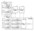
- FIG. 1 is a block diagram showing a radar apparatus according to Embodiment 1 of the present invention.
- a MIMO radar controller 1 is a beam pointing device that indicates a carrier frequency of N (N is an integer of 2 or more) transmission pulses, a directing direction of the transmitting pulse, and a directing direction of a reflected wave of the transmitting pulse reflected on the target.
- Radar control information such as a timing signal indicating the angle and the time at which the transmission pulse is emitted is output.
- the MIMO radar exciter 2 generates N transmission pulses according to the carrier frequency included in the radar control information output from the MIMO radar controller 1, and outputs the N transmission pulses to the MIMO radar transmitter 4.
- the timing signal included in the radar control information is output to the MIMO radar transmitter 4 and the MIMO radar receiver 7.
- the pulse radiating unit 3 includes a MIMO radar transmitter 4 and transmission antennas 5-1 to 5-N, and radiates N transmission pulses with different carrier frequencies output from the MIMO radar exciter 2 to the space.
- the MIMO radar transmitter 4 includes N transmitters 4-1 to 4-N, and the transmitters 4-1 to 4-N amplify the transmission pulses output from the MIMO radar exciter 2 and amplify them.
- the subsequent transmission pulse is output to transmission antennas 5-1 to 5-N.
- the transmitting antennas 5-1 to 5-N radiate the transmission pulses output from the transmitters 4-1 to 4-N into space.
- the reception antennas 6-1 to 6-M which are M (M is a natural number) antennas, radiate from the transmission antennas 5-1 to 5-N and then are reflected from the transmission pulse reflected by the target existing in the space.
- the MIMO radar receiver 7 includes M receivers 7-1 to 7-M, and the receivers 7-1 to 7-M receive reflected waves received by the receiving antennas 6-1 to 6-M. While amplifying the signal, the frequency of the received signal is frequency-converted to the baseband.
- the receivers 7-1 to 7-M convert the received signal into a digital signal and output the digital received signal to the signal processor 8.
- the signal processor 8 includes pulse compression units 9-1 to 9-M and a reception beam combining unit 10.
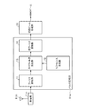
- the pulse compression units 9-1 to 9-M separate the target signals included in the digital reception signals output from the receivers 7-1 to 7-M, and output the beams output from the MIMO radar controller 1. Pulse compression is performed while synthesizing N transmission pulses according to the directivity angle. That is, the pulse compression units 9-1 to 9-M perform a process of obtaining a frequency spectrum of the received signal by performing Fourier transform on the digital received signal output from the receivers 7-1 to 7-M. Further, the pulse compression units 9-1 to 9-M calculate the spectral product of the pulse compression reference determined by the beam directivity angle and the carrier frequency output from the MIMO radar controller 1 and the frequency spectrum of the received signal.
- the reception beam combining unit 10 combines the reception beams output from the pulse compression units 9-1 to 9-M in accordance with the beam directivity angles output from the MIMO radar controller 1, and the MIMO which is a combined signal of the reception beams A process of outputting a beam is performed.
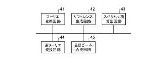
- FIG. 3 is a hardware configuration diagram of the signal processor 8 in the radar apparatus according to Embodiment 1 of the present invention.
- the Fourier transform unit 11 is realized by, for example, the Fourier transform circuit 41 shown in FIG. 3.
- the Fourier transform unit 11 performs Fourier transform on the digital received signal output from the receiver 7-m, and receives the received signal.
- a process for obtaining the frequency spectrum of the signal is performed.
- the reference generation unit 12 is realized by, for example, the reference generation circuit 42 shown in FIG. 3, and performs a process of generating a reference for pulse compression determined by the beam directivity angle and the carrier frequency output from the MIMO radar controller 1. To do.
- the spectral product calculation unit 13 is realized by, for example, the spectral product calculation circuit 43 shown in FIG. 3, and calculates the spectral product of the frequency spectrum obtained by the Fourier transform unit 11 and the reference generated by the reference generation unit 12. Perform the process.
- the inverse Fourier transform unit 14 is realized by, for example, the inverse Fourier transform circuit 44 shown in FIG. 3, and performs the inverse Fourier transform on the spectrum product calculated by the spectrum product calculation unit 13 and receives the inverse Fourier transform result of the spectrum product. Processing to output as a beam is performed.
- the reception beam combining unit 10 is realized by, for example, a reception beam combining circuit 45 shown in FIG.
- the Fourier transform unit 11, the reference generation unit 12, the spectral product calculation unit 13, the inverse Fourier transform unit 14, which are components of the pulse compression unit 9-m (m 1,..., M), and the reception
- the beam combining unit 10 is realized by dedicated hardware as shown in FIG. 3, that is, a Fourier transform circuit 41, a reference generation circuit 42, a spectrum product calculation circuit 43, an inverse Fourier transform circuit 44, and a reception beam synthesis circuit 45.
- the Fourier transform circuit 41, the reference generation circuit 42, the spectral product calculation circuit 43, the inverse Fourier transform circuit 44, and the reception beam synthesis circuit 45 are, for example, a single circuit, a composite circuit, a programmed processor, and a parallel program.
- a processor, an application specific integrated circuit (ASIC), a field-programmable gate array (FPGA), or a combination thereof is applicable.
- the components of m and the reception beam combining unit 10 may be realized by software, firmware, or a combination of software and firmware.
- Software and firmware are stored as programs in the memory of the computer.
- the computer means hardware that executes a program, and includes, for example, a CPU (Central Processing Unit), a central processing unit, a processing unit, an arithmetic unit, a microprocessor, a microcomputer, a processor, a DSP (Digital Signal Processor), and the like. .
- the memory of the computer is, for example, a RAM (Random Access Memory), a ROM (Read Only Memory), a flash memory, an EPROM (Erasable Programmable Read Only Memory), or an EEPROM (Electrically Erasable Memory).
- a RAM Random Access Memory
- ROM Read Only Memory
- flash memory an EPROM (Erasable Programmable Read Only Memory)
- EEPROM Electrically Erasable Memory
- FIG. 4 shows pulse compression.
- the components of the unit 9-m and the reception beam combining unit 10 are implemented by software, firmware, etc.
- the components of the pulse compression unit 9-m and some of the components in the reception beam combining unit 10 are shown. May be realized by dedicated hardware, and the remaining components may be realized by software, firmware, or the like.
- FIG. 6 is a block diagram showing the reference generation unit 12 in the radar apparatus according to Embodiment 1 of the present invention.
- the frequency offset unit 21 gives a plurality of offsets to the N references according to the carrier frequency output from the MIMO radar controller 1, so that the frequency A process of obtaining N references with different values is performed.
- a transmission pulse output from the transmitter 4-1 can be used as a replica of the transmission pulse.
- the load multiplying unit 22 performs a process of multiplying N references obtained by the frequency offset unit 21 by a transmission beam weight (load) corresponding to the beam directivity angle output from the MIMO radar controller 1.
- the reference combining unit 23 performs a process of combining N references multiplied by the transmission beam weights by the load multiplying unit 22.
- the frequency spectrum calculation unit 24 performs a process of calculating the reference frequency spectrum synthesized by the reference synthesis unit 23.
- the window function multiplication unit 25 multiplies the frequency spectrum calculated by the frequency spectrum calculation unit 24 by the window function, and outputs the frequency spectrum after the window function multiplication to the spectrum product calculation unit 13 as a reference for pulse compression. carry out.
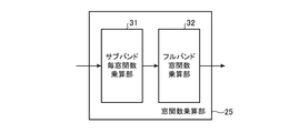
- FIG. 7 is a block diagram showing the window function multiplier 25 in the radar apparatus according to Embodiment 1 of the present invention.
- a subband window function multiplication unit 31 performs first window function multiplication processing for multiplying each subband of the frequency spectrum calculated by the frequency spectrum calculation unit 24 by a window function corresponding to each subband. Part.
- the full band window function multiplication unit 32 multiplies the output signal of the subband window function multiplication unit 31 by a window function corresponding to the entire frequency spectrum calculated by the frequency spectrum calculation unit 24. It is a processing unit.
- the subband window function multiplier 31 is provided in the preceding stage of the full band window function multiplier 32, but the subband window function multiplier 31 is provided in the subsequent stage of the full band window function multiplier 32. It may be provided.
- the MIMO radar controller 1 then includes a beam directivity angle ⁇ b indicating a carrier frequency f n (RF) of N transmission pulses, a directivity direction of the transmit pulse, and a directivity direction of a reflected wave of the transmit pulse reflected on the target, Radar control information such as a timing signal indicating the time at which the transmission pulse is emitted is output to the MIMO radar exciter 2 and the signal processor 8.
- a beam directivity angle ⁇ b indicating a carrier frequency f n (RF) of N transmission pulses, a directivity direction of the transmit pulse, and a directivity direction of a reflected wave of the transmit pulse reflected on the target
- Radar control information such as a timing signal indicating the time at which the transmission pulse is emitted is output to the MIMO radar exciter 2 and the signal processor 8.
- r (t) is a pulse subjected to complex linear frequency modulation.
- CPI Coherent Processing Interval
- PRI Pulse Repeat Interval
- Equation (3) R 0 is the distance from the center position of the transmitting antennas 5-1 to 5-N and the receiving antennas 6-1 to 6-M to the target existing in space, and ⁇ 0 is based on the array normal.
- d n (TX) is the position of the transmitting antenna 5-n with respect to the center position
- d m (RX) is the position of the receiving antenna 6-m with reference to the center position
- c Is the speed of light.
- m (t) is expressed by the following equation (4).
- T PRI is a pulse repetition period PRI
- f d is a Doppler frequency based on a target signal having a radial velocity v 0 .
- amplitude due to distance attenuation or the like is omitted.
- Doppler frequency f d by the target signal is expressed by the following equation (5).
- the difference due to the wavelength ⁇ n of the carrier frequency f n (RF) is assumed to be negligible and is expressed using the wavelength ⁇ of the reference carrier frequency f 0 (RF) .
- the transmission / reception path difference between the transmission pulse and the reflection pulse is expressed by the difference of the following expressions (6) and (7) when the wavelength ⁇ of the reference carrier frequency f 0 (RF) is used. Therefore, equation target signal s bar n, represented by (4), m (t) is as shown in the following equation (8).
- f 0 RF
- P m reflected pulse
- the target signal s n, m (t) is divided into equal intervals t l (h ) as shown in the following equation (10). ) .
- ⁇ t is a sampling interval
- ⁇ t ⁇ T PRI is a sampling interval
- l ′ l ⁇ 1.
- Equation (12) the frequency spectrum of the term shown in equation (12) below is as shown in equation (13) below.
- R (f 1 ) represents the frequency spectrum component of r (l′ ⁇ t)
- r n (fd) (R 0 ) is represented by the following equation (14).
- Equation (13) the frequency spectrum s n, m (h) obtained by performing a discrete Fourier transform on the target signal s n, m [l, h] consisting of L samples in the h-th pulse repetition period PRI. Is expressed by the following equation (15).
- the spectrum product of the determined reference for pulse compression and the frequency spectrum of the received signal x m [l, h] is calculated, and the spectrum product is subjected to inverse Fourier transform.
- the frequency spectrum x ′ m (h) of the received signal x m [l, h] as shown in the following equation (17) is obtained by performing a discrete Fourier transform on [l, h], and the frequency spectrum x ′ m (h) is output to the spectrum calculating unit 13 (step ST1 in FIG. 5).
- Expression (17) attention should be paid to the fact that the phase rotation in the hit direction is exp (j2 ⁇ ( ⁇ f n + f d ) h′T PRI ). This is due to the frequency conversion of the RF band target signal at the reference carrier frequency f 0 (RF) .
- a reference is generated (step ST2 in FIG. 5).
- the reference for pulse compression is represented by the following equation (18).
- w win is a window function vector for range side lobe reduction.
- a n (TXb) is a component related to the beam directivity angle ⁇ b with respect to the array normal.
- the frequency offset unit 21 of the reference generation unit 12 sets N different offsets according to the carrier frequency f n (RF) output from the MIMO radar controller 1. By giving the reference, a plurality of references having different frequencies are obtained.
- N references output from the load multiplying unit 22 are expressed as the following Expression (20).
- N 1, ..., N
- Transmission beam weight corresponding to beam pointing angle theta b for example, stored in the internal memory of the load multiplier unit 22. Specifically, for example, and it transmits the beam weight to the beam directivity angle theta b corresponds to 20 degrees, such as transmission beam weights beam pointing angle theta b corresponds to 30 degrees are stored N pieces each.
- the reference synthesis unit 23 of the reference generation unit 12 receives N references after transmission beam weight multiplication from the weight multiplication unit 22, as shown in the following equation (21), the N number of transmission beam weight multiplications By performing complex addition of references, N references are combined, and the combined reference is output to the frequency spectrum calculation unit 24.
- the frequency spectrum calculating unit 24 of the reference generating unit 12 calculates the reference frequency spectrum and outputs the reference frequency spectrum to the window function multiplying unit 25.
- the window function multiplication unit 25 of the reference generation unit 12 receives the reference frequency spectrum from the frequency spectrum calculation unit 24, the window function multiplication unit 25 multiplies the frequency spectrum by the window function vector w win for range side lobe reduction, and the window function.
- the frequency spectrum multiplied by the vector w win is output to the spectrum product calculation unit 13 as a reference for pulse compression shown in Expression (18).
- the window function vector w win for reducing the range side lobe will be described.
- the combined reference output from the reference combining unit 23 is a combination of N references, and the frequency spectrum of the N references is only the offset given by the frequency offset unit 21 on the frequency axis. is seperated.
- the window function vector w win for reducing the range side lobe the window function vector w n (sub) for each subband spectrum #n and the window function vector for the entire frequency occupied by the combined reference w (full) is set.
- Equation (22) below shows the relationship between the window function vector w win for reducing the range side lobe, the window function vector w n (sub), and the window function vector w (full) .
- the window function vector w 3 (sub) is multiplied for the subband spectrum # 3.
- the subband spectrum # 3 has a value multiplied by the window function vector w 3 (sub)
- the subband spectra # 1, # 2, and # 4 have values of approximately zero.
- the full band window function multiplier 32 of the window function multiplier 25 multiplies the entire output signal of the subband window function multiplier 31 by the window function. That is, the full-band window function multiplier 32 multiplies a window function vector w (full) in the entire sub-band spectrum # 1 ⁇ # N.
- the spectrum of the frequency spectrum x ′ m (h) and the reference for pulse compression is obtained as shown in the following equation (23).
- the product x m ( ⁇ b, h) is calculated (step ST3 in FIG. 5).
- the noise n m ′ included in the frequency spectrum x ′ m (h) is ignored.
- the spectrum product x m ( ⁇ b, h) shown in the equation (23 ) is expressed by the following equation (24).
- ⁇ is an off-boresite angle that is a difference between the beam directing angle ⁇ b and the target orientation ⁇ 0, and b n (TX) ( ⁇ ) is expressed by the following Expression (27).
- ⁇ ⁇ 0 is referred to as an off-bore site target
- the symbol “ ⁇ ” cannot be added above the letter “a” because of the electronic application, so it is represented as “a tilde”.
- D n (f d ) is a diagonal matrix related to the Doppler frequency f d shown in the following equation (30)
- a (R 0 ) is a distance R as shown in the following equation (31). Steering vector for zero .
- the spectral product x m ( ⁇ b, h) shown in Expression (26 ) is as shown in Expression (32) below.
- the spectral product x m ( ⁇ b, h) shown in Expression (32) is a general form of vector expression in the spectral product, and is an output of the spectral product calculation unit 13.
- the following equation (33) is established with respect to the Doppler frequency f d and the target orientation ⁇ 0 .
- the spectral product x m ( ⁇ b, h) shown in the equation (32) is expressed by the following equation (34).
- the phase of a (R 0 ) shows a linear change according to the distance R 0 with respect to the frequency sample direction f 1
- the phase of the spectral product x m ( ⁇ b, h) is also the same. It is changing linearly. Therefore, it can be seen that transmission beam synthesis with a window function w win and pulse compression are performed simultaneously by inverse Fourier transform.
- the combined output z m ( ⁇ b) (R) of the transmission beam for an arbitrary distance R can be obtained by multiplying the spectrum product x m ( ⁇ b, h) by the weight vector w PC (R) shown in the following equation (35). . Therefore, the combined output z m ( ⁇ b) (R) of the transmission beam is expressed by the following equation (36).
- Expression (36) the sum of components in-phased with respect to the transmission beam direction is simultaneously obtained, and transmission beam synthesis is also performed.
- the calculation of Expression (36) is obtained for each range bin using the inverse Fourier transform.
- the calculation result of Expression (36) obtained for each range bin is the output signal of the inverse Fourier transform unit 14.
- the receiving beam combining unit 10 When receiving beam from the inverse Fourier transform unit 14 of the pulse compression units 9-1 to 9-M, the receiving beam combining unit 10 outputs the received beam from the MIMO radar controller 1 as shown in the following equation (37). accordance beam pointing angle theta b, synthesizes the M receive beam, and outputs the MIMO beam is a composite signal of the received beam to the outside (step ST5 in FIG. 5).
- the frequency spectrum of the received signal is obtained, the spectrum product of the reference spectrum for pulse compression determined from the beam pointing angle indicating the direction of transmission pulse and the carrier frequency and the frequency spectrum is calculated, and the spectrum product is inverse Fourier transformed.
- the reception beam combining unit 10 can generate a MIMO beam by performing only one Fourier transform and one inverse Fourier transform, so that the operation scale can be reduced. it can.
- the reference generation unit 12 of the pulse compression unit 9-m multiplies the frequency spectrum calculated by the frequency spectrum calculation unit 24 by the window function, and the frequency after the window function multiplication is performed. Since the window function multiplication unit 25 that outputs the spectrum to the spectrum product calculation unit 13 as a reference for pulse compression is provided, there is an effect that a low-range side lobe of the MIMO beam can be realized.
- FIG. 9 is a hardware configuration diagram of the signal processor 8 in the radar apparatus according to Embodiment 2 of the present invention. 8 and 9, the same reference numerals as those in FIGS. 2 and 3 indicate the same or corresponding parts, and the description thereof will be omitted.
- the reception beam output unit 64 is realized by, for example, the reception beam output circuit 74 shown in FIG. 9, and is based on the inverse Fourier transform units 63-1 to 63-N according to the beam directivity angle output from the MIMO radar controller 1. A process of combining the inverse Fourier transform results and outputting the combined inverse Fourier transform results to the reception beam combining unit 10 as a reception beam is performed.
- the conversion units 63-1 to 63-N, the reception beam output unit 64, and the reception beam combining unit 10 include dedicated hardware as shown in FIG. 9, that is, a Fourier transform circuit 41, a reference generation circuit 71, a spectrum integration It is assumed that the output circuit 72, the inverse Fourier transform circuit 73, the reception beam output circuit 74, and the reception beam synthesis circuit 45 are realized.
- the Fourier transform circuit 41, the reference generation circuit 71, the spectral product calculation circuit 72, the inverse Fourier transform circuit 73, the reception beam output circuit 74, and the reception beam synthesis circuit 45 are, for example, a single circuit, a composite circuit, or a programmed circuit.
- a processor, a processor programmed in parallel, an ASIC, an FPGA, or a combination thereof is applicable.
- the components of m and the reception beam combining unit 10 may be realized by software, firmware, or a combination of software and firmware.
- the Fourier transform unit 11, the reference generation unit 61, the spectral product calculation units 62-1 to 62-N, the inverse Fourier A program for causing the computer to execute the processing procedures of the conversion units 63-1 to 63-N, the reception beam output unit 64, and the reception beam combining unit 10 is stored in the memory 51 shown in FIG.
- the program stored in the program may be executed.
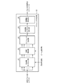
- FIG. 10 is a block diagram showing the reference generation unit 61 in the radar apparatus according to Embodiment 2 of the present invention.
- the reference combining unit 81 performs a process of combining N references obtained by the frequency offset unit 21.
- the frequency spectrum calculation unit 82 performs a process of calculating the frequency spectrum of the reference synthesized by the reference synthesis unit 81.
- a first window function multiplication processing unit that multiplies the spectral component by a window function corresponding to subband #n.
- the full band window function multiplying unit 92 multiplies the output signal of the subband window function multiplying unit 91 by a window function corresponding to the entire frequency spectrum calculated by the frequency spectrum calculating unit 82.
- the subband window function multiplier 91 is provided before the full band window function multiplier 92, but the subband window function multiplier 91 is provided after the full band window function multiplier 92. It may be.
- the processing is the same as in the first embodiment, and therefore, the processing content of the pulse compression unit 9-m will be mainly described here.
- the reference for pulse compression in the subbands # 1 to #N is expressed by the following equation (38).
- w win (n) is a window function vector for reducing the range side lobe in subband #n, and is regarded as 0 in subbands other than subband #n.
- the frequency offset unit 21 of the reference generation unit 61 receives N references R as replicas of transmission pulses, and sets N different offsets according to the carrier frequency f n (RF) output from the MIMO radar controller 1. By giving the reference, a plurality of references having different frequencies are obtained.
- the reference synthesis unit 81 of the reference generation unit 61 synthesizes the N references and outputs the synthesized reference to the frequency spectrum calculation unit 82.
- the frequency spectrum calculation unit 82 of the reference generation unit 61 receives the combined reference from the reference synthesis unit 81, the frequency spectrum calculation unit 82 calculates the frequency spectrum of the reference, and the frequency spectrum of the reference is converted into the window function multiplication units 83-1 to 83-. Output to N.
- the spectral component in #n is multiplied by the window function vector w win (n) for reducing the range side lobe in subband #n, and the spectral component after the window function multiplication is expressed by subband #n shown in Expression (38). Is output to the spectral product calculation unit 62-n as a reference for pulse compression in FIG.
- the window function vector w win (n) for reducing the range side lobe in subband #n will be described.
- the combined reference output from the reference combining unit 81 is a combination of N references, and the frequency spectrum of the N references is only the offset given by the frequency offset unit 21 on the frequency axis. is seperated.
- w n (sub) and a window function vector w (full) for the entire frequency occupied by the combined reference are set.
- Expression (40) below shows the relationship between the window function vector w win (n) for reducing the range side lobe, the window function vector w n (sub), and the window function vector w (full) .
- the subband spectrum # 2 has a value multiplied by the window function vector w 2 (sub) , and the subband spectra # 1, # 3, and # 4 have substantially zero values.
- the spectrum product x n, m ( ⁇ b, h) is expressed by the following equation (41). It is expressed in
- the second embodiment as in the first embodiment, it is assumed that the following equation (42) holds with respect to the Doppler frequency f d.
- the spectral product x n, m ( ⁇ b, h) shown in the equation (41) is expressed by the following equation (43).
- the phase of a (R 0 ) shows a linear change according to the distance R 0 with respect to the frequency sample direction f 1
- the phase of the spectral product x n, m ( ⁇ b, h) is also Similarly, it changes linearly. Therefore, it can be seen that transmission beam synthesis with a window function w win (n) and pulse compression are performed simultaneously by inverse Fourier transform.
- the compressed output y n, m ( ⁇ b) (R) of the subband pulse for an arbitrary distance R can be obtained by multiplying the spectrum vector x n, m ( ⁇ b, h) by the weight vector w PC (R). Therefore, the compressed output y n, m ( ⁇ b) (R) of the subband pulse is expressed by the following equation (44).
- the calculation of Expression (44) is obtained for each range bin using the inverse Fourier transform.
- the calculation result of Expression (44) obtained for each range bin becomes the output signal of the inverse Fourier transform unit 63-n.
- a range-dependent transmission beam weight w (TXb) (R) determined from the above is set.
- C (R) is a matrix depending on the distance to the target, and is given from the MIMO radar control 1 in a fixed or adaptive manner.
- the reception beam output unit 64 performs complex synthesis while multiplying the range-dependent transmission beam weight w (TXb) (R) shown in Expression (47) by the vectorized y m ( ⁇ b) (R) shown in Expression (45). By doing so, the reception beam z m ( ⁇ b) (R) to be output to the reception beam combining unit 10 is calculated.
- C (R) is included in Expression (48)
- transmission beam synthesis is dependent on the range.
- receiving beam combining unit 10 When receiving beam z m ( ⁇ b) (R) is received from receiving beam output unit 64 of pulse compression units 9-1 to 9-M, receiving beam combining unit 10 performs MIMO as shown in the following equation (49). In accordance with the beam directivity angle ⁇ b output from the radar controller 1, M received beams z m ( ⁇ b) (R) are synthesized, and a MIMO beam which is a synthesized signal Z ( ⁇ b) (R) of the received beams. Is output to the outside.
- the frequency spectrum of the received signal is obtained, the spectrum product of the reference spectrum for pulse compression determined from the beam pointing angle indicating the direction of transmission pulse and the carrier frequency and the frequency spectrum is calculated, and the spectrum product is inverse Fourier transformed.
- the reception beam combining unit 10 can generate a MIMO beam only by performing one Fourier transform and N inverse Fourier transforms, so that the operation scale can be reduced. it can.
- the reference generation unit 61 includes the frequency offset unit 21, the reference synthesis unit 81, the frequency spectrum calculation unit 82, and the window function multiplication units 83-1 to 83-N.
- the reference generation unit 61 includes a frequency offset unit 21, frequency spectrum calculation units 101-1 to 101-N, and window function multiplication units 102-1 to 102-N. It may be.
- FIG. 12 is a block diagram showing the reference generator 61 in the radar apparatus according to Embodiment 3 of the present invention.
- the full band window function multiplying unit 112 multiplies the output signal of the subband window function multiplying unit 111 by a window function corresponding to the entire frequency spectrum calculated by the frequency spectrum calculating unit 101-n.
- a multiplication processing unit In the example of FIG. 13, the subband window function multiplier 111 is provided before the full band window function multiplier 112, but the subband window function multiplier 111 is provided after the full band window function multiplier 112. It may be.
- the frequency offset unit 21 of the reference generation unit 61 receives the N references R as replicas of transmission pulses, and similarly to the second embodiment, the carrier frequency f n (RF ) To give different offsets to N references, thereby obtaining a plurality of references having different frequencies.
- the window function multiplication unit 102-n calculates the reference frequency spectrum
- the spectral component in subband #n is multiplied by the window function vector w win (n) for reducing the range side lobe in subband #n, and the spectral component after the window function multiplication is expressed by equation (38). )
- equation (38) As a reference for pulse compression in subband #n shown in FIG.
- the subband spectrum # 2 has a value multiplied by the window function vector w 2 (sub) , and the subband spectra # 1, # 3, and # 4 have substantially zero values.
- this Embodiment 3 like the said Embodiment 2, there exists an effect which can reduce the frequency
- the configuration can be simplified as compared with the second embodiment.
- Embodiment 4 FIG.
- FIG. 14 is a block diagram showing a part of a radar apparatus according to Embodiment 4 of the present invention.
- the pulse Doppler filter 121 is realized by, for example, a filter circuit that performs discrete Fourier transform.
- the pulse Doppler filter 121 receives the receiver 7-m (for each pulse repetition period PRI of transmission pulses radiated from the transmission antennas 5-1 to 5-N.
- the present embodiment is the same as the above Embodiments 1 to 3. Therefore, here, the pulse Doppler filter 121 and the Doppler compensation units 122-1 to 122 -H Processing contents will be described.
- the equation (33) is established for the Doppler frequency f d and the target orientation ⁇ 0.
- the steering vector a (R 0 for the distance R 0 is established. ) Includes a phase jump. Therefore, even if the transmission beams in the first to third embodiments are combined, the range sidelobe characteristic is deteriorated.
- the fourth embodiment in particular formula with respect to the Doppler frequency f d (33) to disclose the measures if not satisfied.
- the processing contents of the pulse Doppler filter 121 and the Doppler compensation units 122-1 to 122-H will be specifically described below.
- the received signal x m [l, h] before pulse compression is expressed by the above equation (16).
- the receiver noise n m [l, h] is ignored, the above equation is obtained.
- the received signal x m [l, h] before pulse compression is expressed as the following equation (50).
- exp (j2 ⁇ ( ⁇ f n + f d ) h′T PRI ) is a Doppler frequency component observed at the sampling interval T PRI in the hit direction.
- the reciprocal of T PRI is the pulse repetition frequency f PRI , and in the radar apparatus, f d > f PRI, and therefore a situation where the Doppler frequency f d turns may occur.
- the Doppler frequency f d is expressed by the following equation (51).
- j n are integers, representing the number of returns.
- the hit direction reception signal x m [l, h] consisting of H samples is input to the pulse Doppler filter 121, and the Doppler spectrum y m (l) obtained by the pulse Doppler filter 121 is Is expressed as the following equation (54).
- q n (fd (fdd)) is a component that changes in the hit direction in Expression (54), that is, exp (j2 ⁇ ( ⁇ f n (fdd) + f d (fdd) ) h′T PRI ) Is a Doppler spectrum obtained by being input to the pulse Doppler filter 121. Further, the center frequency of the H filters constituting the pulse Doppler filter 121, that is, the analysis Doppler frequency f h is expressed by the following equation (55).
- h 0 is an analysis Doppler bin including a target signal and is referred to as a target Doppler bin. If f PRI / H is Doppler resolution, the relationship shown in the following equation (56) is established.
- the Doppler compensation parameters c (h0) (l) as shown in the following equation (58) are given to the Doppler compensation units 122-1 to 122 -H.
- the Doppler compensation parameter c (h0) (l) is multiplied by the Doppler spectrum [y m (l) ] h0 , whereby the Doppler spectrum [ y m (l) ] Compensation of the Doppler frequency component exp (j2 ⁇ f d l′ ⁇ t) in the range direction at h0 is realized.
- ⁇ f d is referred to as post-compensation Doppler frequency ⁇ f d as shown in the following equation (60).
- Doppler compensation is performed.
- a Doppler frequency component i ⁇ f PRI that cannot be compensated remains.
- the Doppler compensation in the fourth embodiment is a radar device in which no aliasing occurs or a radar device in which aliasing is rare. Application in is desirable.
- Equation (59) is data of a time length that compensates for the Doppler frequency component exp (j2 ⁇ f d l′ ⁇ t) included in the Doppler spectrum [y m (l) ] h0 of the target Doppler bin h 0 shown in Equation (57).
- a series that is, a data series of T PRI .
- c (h0) (l) ⁇ [y m (l) ] h0 is subjected to pulse compression as the received signal x m [l, h] shown in the equation (16).
- the outputs from the receivers 7-1 to 7-M are output for each pulse repetition period PRI of the transmission pulses radiated from the transmission antennas 5-1 to 5-N.
- the received received signal x m [l, h] is sampled a plurality of times to obtain a Doppler spectrum of the received signal x m [l, h], and the H in the Doppler spectrum obtained by the pulse Doppler filter 121 is obtained.
- the present invention is suitable for a radar apparatus that performs a MIMO beam combining using a transmission pulse and combining received signals of respective reflected waves while performing pulse compression.
- 1 MIMO radar controller 2 MIMO radar exciter, 3 pulse radiating unit, 4 MIMO radar transmitter, 4-1 to 4-N transmitter, 5-1 to 5-N transmitting antenna, 6-1 to 6-M Receiving antenna (antenna), 7 MIMO radar receiver, 7-1 to 7-M receiver, 8 signal processor, 9-1 to 9-M pulse compressing unit, 10 receiving beam combining unit, 11 Fourier transform unit, 12 Reference generation unit, 13 spectrum product calculation unit, 14 inverse Fourier transform unit, 21 frequency offset unit, 22 load multiplication unit, 23 reference synthesis unit, 24 frequency spectrum calculation unit, 25 window function multiplication unit, 31 subband per window function multiplication Part (first window function multiplication processing part), 32 full band window function multiplication part (second window function multiplication processing part), 41 Fourier transform Circuit, 42 reference generation circuit, 43 spectral product calculation circuit, 44 inverse Fourier transform circuit, 51 memory, 52 processor, 61 reference generation unit, 62-1 to 62-N spectral product calculation unit, 63-1 to 63-N reverse Fourier transform unit, 64 receive beam output unit,
Landscapes
- Engineering & Computer Science (AREA)
- Radar, Positioning & Navigation (AREA)
- Remote Sensing (AREA)
- Computer Networks & Wireless Communication (AREA)
- Physics & Mathematics (AREA)
- General Physics & Mathematics (AREA)
- Radar Systems Or Details Thereof (AREA)
Priority Applications (5)
| Application Number | Priority Date | Filing Date | Title |
|---|---|---|---|
| US16/093,430 US10859690B2 (en) | 2016-04-18 | 2016-04-18 | Radar apparatus |
| JP2018512658A JP6373528B2 (ja) | 2016-04-18 | 2016-04-18 | レーダ装置 |
| PCT/JP2016/062247 WO2017183080A1 (ja) | 2016-04-18 | 2016-04-18 | レーダ装置 |
| EP16899354.1A EP3432025B1 (de) | 2016-04-18 | 2016-04-18 | Radarvorrichtung |
| CA3020072A CA3020072C (en) | 2016-04-18 | 2016-04-18 | Radar apparatus |
Applications Claiming Priority (1)
| Application Number | Priority Date | Filing Date | Title |
|---|---|---|---|
| PCT/JP2016/062247 WO2017183080A1 (ja) | 2016-04-18 | 2016-04-18 | レーダ装置 |
Publications (1)
| Publication Number | Publication Date |
|---|---|
| WO2017183080A1 true WO2017183080A1 (ja) | 2017-10-26 |
Family
ID=60116625
Family Applications (1)
| Application Number | Title | Priority Date | Filing Date |
|---|---|---|---|
| PCT/JP2016/062247 Ceased WO2017183080A1 (ja) | 2016-04-18 | 2016-04-18 | レーダ装置 |
Country Status (5)
| Country | Link |
|---|---|
| US (1) | US10859690B2 (de) |
| EP (1) | EP3432025B1 (de) |
| JP (1) | JP6373528B2 (de) |
| CA (1) | CA3020072C (de) |
| WO (1) | WO2017183080A1 (de) |
Cited By (1)
| Publication number | Priority date | Publication date | Assignee | Title |
|---|---|---|---|---|
| JP2024501466A (ja) * | 2020-12-15 | 2024-01-12 | クアルコム,インコーポレイテッド | 自動車レーダーにおける高速ターゲット検出のための動き補償 |
Families Citing this family (2)
| Publication number | Priority date | Publication date | Assignee | Title |
|---|---|---|---|---|
| US11205844B2 (en) * | 2019-07-08 | 2021-12-21 | GM Global Technology Operations LLC | Beam skew mitigation using non-linear frequency modulation signals |
| DE112021006774T5 (de) * | 2021-03-11 | 2023-11-02 | Mitsubishi Electric Corporation | Radarvorrichtung und fahrzeuginterne vorrichtung mit radarvorrichtung |
Citations (4)
| Publication number | Priority date | Publication date | Assignee | Title |
|---|---|---|---|---|
| JP2012068224A (ja) * | 2010-08-23 | 2012-04-05 | Toshiba Corp | Mimoレーダシステム、送信装置、受信装置及びmimoレーダ信号処理方法 |
| JP2015025668A (ja) * | 2013-07-24 | 2015-02-05 | 三菱電機株式会社 | レーダ装置 |
| US20160018512A1 (en) * | 2013-06-21 | 2016-01-21 | Wuhan University | Method for Generating and Compressing Multi-Sweep-Frequency Radar Signals |
| JP2016050778A (ja) * | 2014-08-28 | 2016-04-11 | 日本無線株式会社 | 直交分離装置および直交分離方法 |
Family Cites Families (4)
| Publication number | Priority date | Publication date | Assignee | Title |
|---|---|---|---|---|
| US7714782B2 (en) * | 2004-01-13 | 2010-05-11 | Dennis Willard Davis | Phase arrays exploiting geometry phase and methods of creating such arrays |
| US9121943B2 (en) * | 2011-05-23 | 2015-09-01 | Sony Corporation | Beam forming device and method |
| KR20130127347A (ko) * | 2012-05-10 | 2013-11-22 | 삼성전자주식회사 | 아날로그 및 디지털 하이브리드 빔포밍을 통한 통신 방법 및 장치 |
| JP6031267B2 (ja) * | 2012-06-21 | 2016-11-24 | 古野電気株式会社 | 干渉検出装置、干渉除去器、レーダ装置、干渉検出方法および干渉検出用プログラム |
-
2016
- 2016-04-18 JP JP2018512658A patent/JP6373528B2/ja active Active
- 2016-04-18 EP EP16899354.1A patent/EP3432025B1/de active Active
- 2016-04-18 WO PCT/JP2016/062247 patent/WO2017183080A1/ja not_active Ceased
- 2016-04-18 US US16/093,430 patent/US10859690B2/en active Active
- 2016-04-18 CA CA3020072A patent/CA3020072C/en active Active
Patent Citations (4)
| Publication number | Priority date | Publication date | Assignee | Title |
|---|---|---|---|---|
| JP2012068224A (ja) * | 2010-08-23 | 2012-04-05 | Toshiba Corp | Mimoレーダシステム、送信装置、受信装置及びmimoレーダ信号処理方法 |
| US20160018512A1 (en) * | 2013-06-21 | 2016-01-21 | Wuhan University | Method for Generating and Compressing Multi-Sweep-Frequency Radar Signals |
| JP2015025668A (ja) * | 2013-07-24 | 2015-02-05 | 三菱電機株式会社 | レーダ装置 |
| JP2016050778A (ja) * | 2014-08-28 | 2016-04-11 | 日本無線株式会社 | 直交分離装置および直交分離方法 |
Cited By (1)
| Publication number | Priority date | Publication date | Assignee | Title |
|---|---|---|---|---|
| JP2024501466A (ja) * | 2020-12-15 | 2024-01-12 | クアルコム,インコーポレイテッド | 自動車レーダーにおける高速ターゲット検出のための動き補償 |
Also Published As
| Publication number | Publication date |
|---|---|
| CA3020072C (en) | 2019-01-22 |
| EP3432025A4 (de) | 2019-03-20 |
| JPWO2017183080A1 (ja) | 2018-09-06 |
| CA3020072A1 (en) | 2017-10-26 |
| JP6373528B2 (ja) | 2018-08-15 |
| US10859690B2 (en) | 2020-12-08 |
| EP3432025B1 (de) | 2020-04-01 |
| EP3432025A1 (de) | 2019-01-23 |
| US20190064336A1 (en) | 2019-02-28 |
Similar Documents
| Publication | Publication Date | Title |
|---|---|---|
| US11940524B2 (en) | Radar apparatus and radar method | |
| US9070972B2 (en) | Wideband beam forming device; wideband beam steering device and corresponding methods | |
| CN108713154B (zh) | 雷达装置 | |
| JP5848944B2 (ja) | レーダ装置 | |
| CN108603928B (zh) | 用于降低由雷达系统中的相位噪声引起的干扰的方法和系统 | |
| JP6391888B2 (ja) | レーダ装置 | |
| JP5863443B2 (ja) | レーダ装置 | |
| US20250231284A1 (en) | Radar device | |
| JP2010286403A (ja) | 測角装置、モノパルス測角装置、モノパルスレーダ、マルチスタティックレーダ | |
| JP6373528B2 (ja) | レーダ装置 | |
| Ahmad et al. | A beamforming approach to stepped-frequency synthetic aperture through-the-wall radar imaging | |
| JP6245797B2 (ja) | レーダ装置 | |
| JP6289252B2 (ja) | レーダ装置 | |
| He et al. | Near-field radar imaging using MMIC-based large-aperture array | |
| WO2023210451A1 (ja) | 測位システムおよびそれを備える車両、並びに測位方法 | |
| JP6573748B2 (ja) | レーダ装置 | |
| JP7143146B2 (ja) | レーダシステム及びそのレーダ信号処理方法 | |
| JP2020056592A (ja) | レーダ装置 | |
| JP6415392B2 (ja) | 信号処理装置 | |
| JP6615405B2 (ja) | レーダ装置 | |
| JP6220138B2 (ja) | 積分装置 | |
| JP6271834B2 (ja) | レーダ装置 | |
| JP2003098251A (ja) | レーダ装置 | |
| JPH01224684A (ja) | フィードスルーナリング回路 | |
| WO2025099916A1 (ja) | レーダ信号処理装置、レーダ信号処理方法及びレーダ装置 |
Legal Events
| Date | Code | Title | Description |
|---|---|---|---|
| ENP | Entry into the national phase |
Ref document number: 2018512658 Country of ref document: JP Kind code of ref document: A |
|
| ENP | Entry into the national phase |
Ref document number: 3020072 Country of ref document: CA |
|
| WWE | Wipo information: entry into national phase |
Ref document number: 2016899354 Country of ref document: EP |
|
| NENP | Non-entry into the national phase |
Ref country code: DE |
|
| ENP | Entry into the national phase |
Ref document number: 2016899354 Country of ref document: EP Effective date: 20181016 |
|
| 121 | Ep: the epo has been informed by wipo that ep was designated in this application |
Ref document number: 16899354 Country of ref document: EP Kind code of ref document: A1 |