WO2017183097A1 - Dispositif de radar - Google Patents
Dispositif de radar Download PDFInfo
- Publication number
- WO2017183097A1 WO2017183097A1 PCT/JP2016/062327 JP2016062327W WO2017183097A1 WO 2017183097 A1 WO2017183097 A1 WO 2017183097A1 JP 2016062327 W JP2016062327 W JP 2016062327W WO 2017183097 A1 WO2017183097 A1 WO 2017183097A1
- Authority
- WO
- WIPO (PCT)
- Prior art keywords
- units
- target
- signal
- output signals
- window function
- Prior art date
- Legal status (The legal status is an assumption and is not a legal conclusion. Google has not performed a legal analysis and makes no representation as to the accuracy of the status listed.)
- Ceased
Links
Images





Classifications
-
- G—PHYSICS
- G01—MEASURING; TESTING
- G01S—RADIO DIRECTION-FINDING; RADIO NAVIGATION; DETERMINING DISTANCE OR VELOCITY BY USE OF RADIO WAVES; LOCATING OR PRESENCE-DETECTING BY USE OF THE REFLECTION OR RERADIATION OF RADIO WAVES; ANALOGOUS ARRANGEMENTS USING OTHER WAVES
- G01S13/00—Systems using the reflection or reradiation of radio waves, e.g. radar systems; Analogous systems using reflection or reradiation of waves whose nature or wavelength is irrelevant or unspecified
- G01S13/02—Systems using reflection of radio waves, e.g. primary radar systems; Analogous systems
- G01S13/06—Systems determining position data of a target
- G01S13/08—Systems for measuring distance only
- G01S13/32—Systems for measuring distance only using transmission of continuous waves, whether amplitude-, frequency-, or phase-modulated, or unmodulated
- G01S13/34—Systems for measuring distance only using transmission of continuous waves, whether amplitude-, frequency-, or phase-modulated, or unmodulated using transmission of continuous, frequency-modulated waves while heterodyning the received signal, or a signal derived therefrom, with a locally-generated signal related to the contemporaneously transmitted signal
- G01S13/343—Systems for measuring distance only using transmission of continuous waves, whether amplitude-, frequency-, or phase-modulated, or unmodulated using transmission of continuous, frequency-modulated waves while heterodyning the received signal, or a signal derived therefrom, with a locally-generated signal related to the contemporaneously transmitted signal using sawtooth modulation
-
- G—PHYSICS
- G01—MEASURING; TESTING
- G01S—RADIO DIRECTION-FINDING; RADIO NAVIGATION; DETERMINING DISTANCE OR VELOCITY BY USE OF RADIO WAVES; LOCATING OR PRESENCE-DETECTING BY USE OF THE REFLECTION OR RERADIATION OF RADIO WAVES; ANALOGOUS ARRANGEMENTS USING OTHER WAVES
- G01S13/00—Systems using the reflection or reradiation of radio waves, e.g. radar systems; Analogous systems using reflection or reradiation of waves whose nature or wavelength is irrelevant or unspecified
- G01S13/02—Systems using reflection of radio waves, e.g. primary radar systems; Analogous systems
- G01S13/50—Systems of measurement based on relative movement of target
- G01S13/52—Discriminating between fixed and moving objects or between objects moving at different speeds
- G01S13/522—Discriminating between fixed and moving objects or between objects moving at different speeds using transmissions of interrupted pulse modulated waves
- G01S13/524—Discriminating between fixed and moving objects or between objects moving at different speeds using transmissions of interrupted pulse modulated waves based upon the phase or frequency shift resulting from movement of objects, with reference to the transmitted signals, e.g. coherent MTi
- G01S13/53—Discriminating between fixed and moving objects or between objects moving at different speeds using transmissions of interrupted pulse modulated waves based upon the phase or frequency shift resulting from movement of objects, with reference to the transmitted signals, e.g. coherent MTi performing filtering on a single spectral line and associated with one or more range gates with a phase detector or a frequency mixer to extract the Doppler information, e.g. pulse Doppler radar
-
- G—PHYSICS
- G01—MEASURING; TESTING
- G01S—RADIO DIRECTION-FINDING; RADIO NAVIGATION; DETERMINING DISTANCE OR VELOCITY BY USE OF RADIO WAVES; LOCATING OR PRESENCE-DETECTING BY USE OF THE REFLECTION OR RERADIATION OF RADIO WAVES; ANALOGOUS ARRANGEMENTS USING OTHER WAVES
- G01S7/00—Details of systems according to groups G01S13/00, G01S15/00, G01S17/00
- G01S7/02—Details of systems according to groups G01S13/00, G01S15/00, G01S17/00 of systems according to group G01S13/00
- G01S7/28—Details of pulse systems
- G01S7/285—Receivers
- G01S7/292—Extracting wanted echo-signals
-
- G—PHYSICS
- G01—MEASURING; TESTING
- G01S—RADIO DIRECTION-FINDING; RADIO NAVIGATION; DETERMINING DISTANCE OR VELOCITY BY USE OF RADIO WAVES; LOCATING OR PRESENCE-DETECTING BY USE OF THE REFLECTION OR RERADIATION OF RADIO WAVES; ANALOGOUS ARRANGEMENTS USING OTHER WAVES
- G01S13/00—Systems using the reflection or reradiation of radio waves, e.g. radar systems; Analogous systems using reflection or reradiation of waves whose nature or wavelength is irrelevant or unspecified
- G01S13/02—Systems using reflection of radio waves, e.g. primary radar systems; Analogous systems
- G01S13/06—Systems determining position data of a target
- G01S13/08—Systems for measuring distance only
- G01S13/10—Systems for measuring distance only using transmission of interrupted, pulse modulated waves
- G01S13/26—Systems for measuring distance only using transmission of interrupted, pulse modulated waves wherein the transmitted pulses use a frequency- or phase-modulated carrier wave
- G01S13/28—Systems for measuring distance only using transmission of interrupted, pulse modulated waves wherein the transmitted pulses use a frequency- or phase-modulated carrier wave with time compression of received pulses
-
- G—PHYSICS
- G01—MEASURING; TESTING
- G01S—RADIO DIRECTION-FINDING; RADIO NAVIGATION; DETERMINING DISTANCE OR VELOCITY BY USE OF RADIO WAVES; LOCATING OR PRESENCE-DETECTING BY USE OF THE REFLECTION OR RERADIATION OF RADIO WAVES; ANALOGOUS ARRANGEMENTS USING OTHER WAVES
- G01S13/00—Systems using the reflection or reradiation of radio waves, e.g. radar systems; Analogous systems using reflection or reradiation of waves whose nature or wavelength is irrelevant or unspecified
- G01S13/02—Systems using reflection of radio waves, e.g. primary radar systems; Analogous systems
- G01S13/06—Systems determining position data of a target
- G01S13/08—Systems for measuring distance only
- G01S13/32—Systems for measuring distance only using transmission of continuous waves, whether amplitude-, frequency-, or phase-modulated, or unmodulated
- G01S13/34—Systems for measuring distance only using transmission of continuous waves, whether amplitude-, frequency-, or phase-modulated, or unmodulated using transmission of continuous, frequency-modulated waves while heterodyning the received signal, or a signal derived therefrom, with a locally-generated signal related to the contemporaneously transmitted signal
- G01S13/347—Systems for measuring distance only using transmission of continuous waves, whether amplitude-, frequency-, or phase-modulated, or unmodulated using transmission of continuous, frequency-modulated waves while heterodyning the received signal, or a signal derived therefrom, with a locally-generated signal related to the contemporaneously transmitted signal using more than one modulation frequency
-
- G—PHYSICS
- G01—MEASURING; TESTING
- G01S—RADIO DIRECTION-FINDING; RADIO NAVIGATION; DETERMINING DISTANCE OR VELOCITY BY USE OF RADIO WAVES; LOCATING OR PRESENCE-DETECTING BY USE OF THE REFLECTION OR RERADIATION OF RADIO WAVES; ANALOGOUS ARRANGEMENTS USING OTHER WAVES
- G01S13/00—Systems using the reflection or reradiation of radio waves, e.g. radar systems; Analogous systems using reflection or reradiation of waves whose nature or wavelength is irrelevant or unspecified
- G01S13/02—Systems using reflection of radio waves, e.g. primary radar systems; Analogous systems
- G01S13/06—Systems determining position data of a target
- G01S13/42—Simultaneous measurement of distance and other co-ordinates
-
- G—PHYSICS
- G01—MEASURING; TESTING
- G01S—RADIO DIRECTION-FINDING; RADIO NAVIGATION; DETERMINING DISTANCE OR VELOCITY BY USE OF RADIO WAVES; LOCATING OR PRESENCE-DETECTING BY USE OF THE REFLECTION OR RERADIATION OF RADIO WAVES; ANALOGOUS ARRANGEMENTS USING OTHER WAVES
- G01S13/00—Systems using the reflection or reradiation of radio waves, e.g. radar systems; Analogous systems using reflection or reradiation of waves whose nature or wavelength is irrelevant or unspecified
- G01S13/88—Radar or analogous systems specially adapted for specific applications
- G01S13/89—Radar or analogous systems specially adapted for specific applications for mapping or imaging
- G01S13/90—Radar or analogous systems specially adapted for specific applications for mapping or imaging using synthetic aperture techniques, e.g. synthetic aperture radar [SAR] techniques
- G01S13/904—SAR modes
-
- G—PHYSICS
- G01—MEASURING; TESTING
- G01S—RADIO DIRECTION-FINDING; RADIO NAVIGATION; DETERMINING DISTANCE OR VELOCITY BY USE OF RADIO WAVES; LOCATING OR PRESENCE-DETECTING BY USE OF THE REFLECTION OR RERADIATION OF RADIO WAVES; ANALOGOUS ARRANGEMENTS USING OTHER WAVES
- G01S7/00—Details of systems according to groups G01S13/00, G01S15/00, G01S17/00
- G01S7/02—Details of systems according to groups G01S13/00, G01S15/00, G01S17/00 of systems according to group G01S13/00
- G01S7/28—Details of pulse systems
- G01S7/285—Receivers
- G01S7/292—Extracting wanted echo-signals
- G01S7/2923—Extracting wanted echo-signals based on data belonging to a number of consecutive radar periods
- G01S7/2927—Extracting wanted echo-signals based on data belonging to a number of consecutive radar periods by deriving and controlling a threshold value
-
- G—PHYSICS
- G01—MEASURING; TESTING
- G01S—RADIO DIRECTION-FINDING; RADIO NAVIGATION; DETERMINING DISTANCE OR VELOCITY BY USE OF RADIO WAVES; LOCATING OR PRESENCE-DETECTING BY USE OF THE REFLECTION OR RERADIATION OF RADIO WAVES; ANALOGOUS ARRANGEMENTS USING OTHER WAVES
- G01S13/00—Systems using the reflection or reradiation of radio waves, e.g. radar systems; Analogous systems using reflection or reradiation of waves whose nature or wavelength is irrelevant or unspecified
- G01S13/88—Radar or analogous systems specially adapted for specific applications
- G01S13/89—Radar or analogous systems specially adapted for specific applications for mapping or imaging
- G01S13/90—Radar or analogous systems specially adapted for specific applications for mapping or imaging using synthetic aperture techniques, e.g. synthetic aperture radar [SAR] techniques
- G01S13/904—SAR modes
- G01S13/9047—Doppler beam sharpening mode
-
- G—PHYSICS
- G01—MEASURING; TESTING
- G01S—RADIO DIRECTION-FINDING; RADIO NAVIGATION; DETERMINING DISTANCE OR VELOCITY BY USE OF RADIO WAVES; LOCATING OR PRESENCE-DETECTING BY USE OF THE REFLECTION OR RERADIATION OF RADIO WAVES; ANALOGOUS ARRANGEMENTS USING OTHER WAVES
- G01S7/00—Details of systems according to groups G01S13/00, G01S15/00, G01S17/00
- G01S7/02—Details of systems according to groups G01S13/00, G01S15/00, G01S17/00 of systems according to group G01S13/00
- G01S7/28—Details of pulse systems
- G01S7/285—Receivers
- G01S7/288—Coherent receivers
- G01S7/2883—Coherent receivers using FFT processing
-
- G—PHYSICS
- G01—MEASURING; TESTING
- G01S—RADIO DIRECTION-FINDING; RADIO NAVIGATION; DETERMINING DISTANCE OR VELOCITY BY USE OF RADIO WAVES; LOCATING OR PRESENCE-DETECTING BY USE OF THE REFLECTION OR RERADIATION OF RADIO WAVES; ANALOGOUS ARRANGEMENTS USING OTHER WAVES
- G01S7/00—Details of systems according to groups G01S13/00, G01S15/00, G01S17/00
- G01S7/02—Details of systems according to groups G01S13/00, G01S15/00, G01S17/00 of systems according to group G01S13/00
- G01S7/35—Details of non-pulse systems
- G01S7/352—Receivers
- G01S7/356—Receivers involving particularities of FFT processing
Definitions
- the present invention relates to a radar apparatus that identifies a target position from a delay time from when a radio wave is emitted until a target reflected wave is received and the arrival direction of the reflected radio wave.
- a transmitter generates a plurality of signals having different bands, transmits each signal from a transmission antenna, emits a radio wave, and receives a target reflected wave.
- a radar device that identifies the position of a target from the delay time until it arrives and the arrival direction of the reflected radio wave.
- the present invention has been made to solve such a problem, and an object of the present invention is to obtain a radar apparatus that can eliminate erroneous detection of a target due to an unnecessary peak.
- a radar apparatus includes a transmission unit that simultaneously transmits a plurality of radio waves having different bands from each antenna, a reception unit that receives a radio wave transmitted from the transmission unit and reflected by a target as a target reflected wave, and a reception unit Using the synthesis result of the synthesis processing unit and the synthesis processing unit that suppresses unnecessary peaks generated by the influence of leakage into other bands due to the Doppler frequency and the target reflected wave corresponding to each antenna received at And a detection processing unit for detecting a target.
- the radar apparatus synthesizes the target reflected wave by suppressing unnecessary peaks generated due to the influence of the Doppler frequency leaking into other bands. Thereby, the erroneous detection of the target resulting from an unnecessary peak can be eliminated.
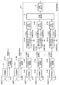
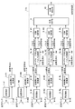
- FIG. 1 is a configuration diagram of a radar apparatus according to the present embodiment.
- the radar apparatus according to the present embodiment includes transmitters 1- # 1 to 1- # M, transmission antennas 2- # 1 to 2- # M, and transmission side A / D converters 3- # 1 to 3- # M, receiving antennas 4- # 1 to 4- # L, receivers 5- # 1 to 5- # L, receiving side A / D converters 6- # 1 to 6- # L, pulse compression unit 7 -# 1-7- # L, transmission DBF (Digital Beam Forming) unit 8- # 1-8- # L, reception DBF unit 9, and target detection unit 10.
- transmitters 1- # 1 to 1- # M the radar apparatus according to the present embodiment includes transmitters 1- # 1 to 1- # M, transmission antennas 2- # 1 to 2- # M, and transmission side A / D converters 3- # 1 to 3- # M, receiving antennas 4- # 1 to 4- # L, receivers 5- # 1 to 5- # L, receiving side A / D converters 6- # 1 to 6- # L, pulse compression unit 7 -# 1-7- #
- Transmitters 1- # 1 to 1- # M are transmitters that generate signals subjected to linear FM modulation, and M (M ⁇ 2) are provided. Transmit antennas 2- # 1 to 2- # M are provided corresponding to transmitters 1- # 1 to 1- # M, and transmit signals generated by transmitters 1- # 1 to 1- # M, respectively. It is an antenna to do.
- the transmission side A / D converters 3- # 1 to 3- # M are A / D converters that convert a transmission signal, which is an analog signal, into a digital signal.
- the receiving antennas 4- # 1 to 4- # L are antennas for receiving radio waves transmitted from the transmitting antennas 2- # 1 to 2- # M and reflected to the target, and L (L ⁇ 2) antennas are received. Is provided.
- Receivers 5- # 1 to 5- # L are receivers that perform band limitation and phase detection on radio waves received by reception antennas 4- # 1 to 4- # L, respectively.
- Receiving side A / D converters 6- # 1 to 6- # L are A / D converters that convert the received signals, which are analog signals output from the receivers 5- # 1 to 5- # L, into digital signals. It is.
- the pulse compression units 7- # 1 to 7- # L are provided with the A / D conversion signals # 1 to #L from the reception side A / D converters 6- # 1 to 6- # L and the transmission side A / D conversion.
- This is a processing unit that performs pulse compression based on the reference signals # 1 to #M output from the devices 3- # 1 to 3- # M, which will be described later.
- the transmission DBF units 8- # 1 to 8- # L are processing units that form and combine transmission beams based on the signals compressed by the pulse compression units 7- # 1 to 7- # L.
- the unit 9 is a processing unit that combines the output signals of the transmission DBF units 8- # 1 to 8- # L with a reception beam.
- the target detection unit 10 is a processing unit that detects the direction and distance in which the target exists based on the output signal of the reception DBF unit 9. Further, a signal processing unit 11 is configured by the pulse compression units 7- # 1 to 7- # L to the target detection unit 10.
- the transmitters 1- # 1 to 1- # M, the transmission antennas 2- # 1 to 2- # M, and the transmission-side A / D converters 3- # 1 to 3- # M are connected to each other from each antenna.
- a transmitter is configured to transmit a plurality of radio waves having different values simultaneously.
- the receiving antennas 4- # 1 to 4- # L and the receivers 5- # 1 to 5- # L constitute a receiving unit that receives a radio wave transmitted from the transmitting unit and reflected to the target as a target reflected wave. ing.
- the receiving side A / D converters 6- # 1 to 6- # L, the pulse compression unit 7- # l, and the transmission DBF units 8- # 1 to 8- # L support each antenna received by the receiving unit.
- a synthesis processing unit is configured to synthesize the target reflected wave by suppressing unnecessary peaks generated due to the influence of leakage into other bands due to the Doppler frequency. Further, the reception DBF unit 9 and the target detection unit 10 constitute a detection processing unit that detects a target using the synthesis result of the synthesis processing unit.
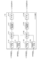
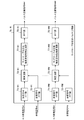
- FIG. 2 is a block diagram showing the internal structure of the pulse compressor 7- # l (1 ⁇ l ⁇ L).
- the pulse compression unit 7- # l includes reception signal FET units 71- # 1 to 71- # M, reference signal FET units 72- # 1 to 72- # M, and multiplication circuits 73- # 1 to 73. -#M, complex window function multiplication circuits 74- # 1 to 74- # M, and IFFT units 75- # 1 to 75- # M.
- the reception signal FET units 71- # 1 to 71- # M perform FFT (Fast Fourier Transform) processing on the A / D conversion signal #l from the reception side A / D converter 6- # l.
- FFT Fast Fourier Transform
- the reference signal FET units 72- # 1 to 72- # M input the output signals of the transmission side A / D converters 3- # 1 to 3- # M as reference signals # 1 to #M, and the respective reference signals This is an arithmetic unit that performs FFT processing on # 1 to #M.
- the multiplication circuits 73- # 1 to 73- # M are complex conjugates of the output signals of the reference signal FET units 72- # 1 to 72- # M to the output signals of the reception signal FET units 71- # 1 to 71- # M. Is a multiplication circuit for multiplying.
- the complex window function multiplication circuits 74- # 1 to 74- # M form notches at positions of unnecessary peaks generated due to Doppler with respect to the output signals of the multiplication circuits 73- # 1 to 73- # M. It is a window function multiplication circuit which multiplies a window function.
- the IFFT units 75- # 1 to 75- # M are arithmetic units that perform IFFT (Inverse Fast Fourier Transform) processing on the output signals of the complex window function multiplying circuits 74- # 1 to 74- # M.
- FIG. 3 is a hardware configuration diagram of the signal processing unit 11 in which the signal processing unit 11 is configured as a signal processing board.
- the illustrated signal processing unit 11 is configured using, for example, an FPGA (Field-Programmable Gate Array) or the like, and includes a processor 111, a memory 112, and a display 113.
- the processor 111 performs pulse compression in the pulse compression unit 7- # 1, DBF processing in the transmission DBF units 8- # 1 to 8- # L, DBF processing in the reception DBF unit 9, and target detection processing in the target detection unit 10. It is.
- the memory 112 is a storage unit for storing a program for realizing the pulse compression unit 7-# 1 to the target detection unit 10 and for use as a work area of the signal processing unit 11.
- the display device 113 is a display device for displaying the processing result of the processor 111.
- the functions of the pulse compression unit 7- # 1 to the target detection unit 10 are realized by the processor 111 executing the program stored in the memory 112.
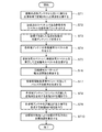
- FIG. 4 is a flowchart showing the operation of the radar apparatus according to the first embodiment.
- Pulsed transmission waves are transmitted by the transmitter 1- # m (1 ⁇ m ⁇ M) and the transmission antenna 2- # m (step ST1).
- the transmission wave is also transmitted to the transmission side A / D converter 3- # m, and the reference signal-# m is output (step ST2).
- FIG. 5 shows frequency modulation of radio waves generated by the transmitters 1- # 1 to 1- # M. Dividing the transmission band into M, transmitter 1- # m generates a transmission wave subjected to linear FM modulation using the mth band.
- a transmission wave is transmitted from the transmission antenna 2- # m. Further, a broken line 501 in FIG.
- an arrow 502 indicates the Doppler frequency.
- a plurality of uncorrelated radio waves are transmitted from the plurality of transmission antennas 2- # 1 to 2- # M, but the transmission bands of the respective transmitters 1- # 1 to 1- # M are slightly different.
- the radio waves that overlap, that is, have a small correlation with each other may be transmitted.
- the transmission wave is reflected by the target and received by reception antenna 4- # 1 to reception antenna 4- # L (step ST3).
- Radio waves received by the receiving antenna 4- # l (1 ⁇ l ⁇ L) are subjected to band limitation and phase detection by the receiver 5- # l, and then transmitted to the receiving A / D converter 6- # l Is done.
- the receiving side A / D converter 6- # l converts the output signal of the receiver 5- # l into a digital signal.
- An A / D conversion signal #l that is an output signal of the reception-side A / D converter 6- # l is transmitted to the reception signal FET units 71- # 1 to 71- # M of the pulse compression unit 7- # l.
- Reception signal FET units 71- # 1 to 71- # M perform an FFT process on the reception signal to generate a reception signal spectrum (step ST4). This received spectrum is assumed to be x1 , m, 1 , ..., xl, m, N.
- the reference signal #m (1 ⁇ m ⁇ M) is transmitted to the reference signal FET units 72- # 1 to 72- # M.
- the reference signal #m is subjected to FFT processing to generate a reference signal spectrum.
- this reference signal spectrum be ym , 1 , ..., ym , N.
- These received signal spectrums x l, m, 1 ,..., X l, m, N and reference signal spectrums ym , 1 ,..., Y m, N are transmitted to the multiplier circuits 73- # 1 to 73- # M. .
- the complex conjugate of the received signal spectrum and the reference signal spectrum is multiplied to generate compressed signal spectra z l, m, 1 ,..., Z l, m, N (steps). ST5).
- * represents a complex conjugate.
- the complex window function multiplier circuit 74- # 1 ⁇ 74- # M, the complex window function w m, 1 ... w m, the complex window function multiplied signal by multiplying the N to the compressed signal spectrum w m, 1zl, m , 1 ,... W m, Nzl, m, N are output (step ST6).
- the complex window function w m, 1 ... W m, N is calculated as an element of the vector w m calculated by the following equation (2).
- 1 represents a 1-row N-column vector with all elements being 1
- I represents a unit vector of N-rows and N-columns
- ⁇ (t) represents a weight obtained by increasing a time domain coefficient corresponding to the pulse width.
- FIG. 6 shows the relationship between the pulse width and the suppression region.
- the suppression region corresponds to a region where the side lobe increases due to cross-correlation. That is, when pulse compression is performed, as shown by a broken line 501 in FIG. 5, an unnecessary peak in which side lobes are increased due to cross-correlation occurs due to leakage due to the influence of the Doppler frequency 502 from an adjacent band. Therefore, a complex window function w m, 1 ...
- W m, N that forms a notch in this unnecessary peak region is created to suppress side lobes that have risen due to cross-correlation.
- the notch width and depth are controlled by the width of the suppression region shown in FIG. 6 and the parameter ⁇ in equation (2). Further, x ′ m, 1 ,..., X ′ m, N represents a received signal created in a pseudo manner.
- Complex window function multiplication signals w m, 1 zl, m, 1 ,... W m, Nzl, m, N output from the complex window function multiplication circuits 74- # 1 to 74- # M are IFFT units 75- # 1-75. -Is transmitted to #M.
- the complex window function multiplication signals w m, 1zl, m, 1 ,... W m, Nzl, m, N are subjected to IFFT processing, and the pulse compression signals ⁇ l, m, 1 ,..., ⁇ l, m, N are generated (step ST7).
- the number n of ⁇ l, m, n represents the range bin number in units of distance resolution determined from the transmission bandwidth B or the like.
- Pulse compression signals ⁇ l, m, 1 ,..., ⁇ l, m, N are transmitted to transmission DBF unit 8- # l.
- the transmission DBF unit 8- # l calculates the phase correction amounts ⁇ 1 ( ⁇ ) to ⁇ M ( ⁇ ) corresponding to the assumed radio wave arrival direction ⁇ and transmission antenna position, and combines the signal g by the following equation (3): l, n ( ⁇ ) is calculated (step ST8).
- Transmission DBF signal g l, n ( ⁇ ) from transmission DBF unit 8- # l is transmitted to reception DBF unit 9.
- the reception DBF unit 9 calculates phase correction amounts ⁇ 1 ( ⁇ ) to ⁇ L ( ⁇ ) corresponding to the radio wave arrival direction ⁇ and the reception antenna position, and combines the signal h n ( ⁇ ) by the following equation (4). Is calculated (step ST9).
- a reception DBF signal h n ( ⁇ ) from the reception DBF unit 9 is transmitted to the target detection unit 10.
- the target detection unit 10 compares the absolute value
- the use of the window function that forms a notch at a position corresponding to the pulse width away from the main lobe can suppress unnecessary peaks caused by Doppler, and erroneous detection of a target. Can be eliminated.
- a transmission unit that simultaneously transmits a plurality of radio waves having different bands from each antenna, and a radio wave that is transmitted from the transmission unit and reflected by the target is a target reflected wave.
- a receiving unit that receives the target reflected wave corresponding to each antenna received by the receiving unit, and a synthesis processing unit that combines and suppresses unnecessary peaks that occur due to the influence of leakage into other bands due to the Doppler frequency, Since the detection processing unit that detects the target using the synthesis result of the synthesis processing unit is provided, erroneous detection of the target due to an unnecessary peak can be eliminated.
- the transmission unit includes M (M ⁇ 2) transmitters that generate signals having waveforms subjected to linear frequency modulation in different bands, and M transmissions.
- the receiving unit limits the bandwidth to the radio waves received by the L (L ⁇ 2) reception antennas that receive the radio waves reflected by the target and the L reception antennas. Since it is configured to include L receivers that perform phase detection, it is possible to provide a receiver for eliminating erroneous detection of a target due to an unnecessary peak.
- the synthesis processing unit includes L reception-side A / D converters that convert the output signal of the reception unit into digital signals, and L reception-side A / D conversions.
- L pulse compression units that perform pulse compression by suppressing unnecessary peaks using the output signals of the transmitters and the output signals of the M transmission side A / D converters, and the mutual generated by the M transmitters Since it is composed of L transmission DBF units for synthesizing output signals of L pulse compression units related to signals in different bands, a synthesis processing unit for eliminating erroneous detection of a target due to an unnecessary peak Can be provided.
- the detection processing unit combines the output signals of the L transmission DBF units with the reception DBF unit, and the noise is the target signal with respect to the output signal of the reception DBF unit. Since it is composed of a target detection unit that detects a target using a threshold set based on a false alarm probability that is erroneously determined, a detection processing unit for eliminating erroneous detection of a target due to an unnecessary peak Can be provided.
- the L pulse compression units each perform M transform processing on the output signal of the receiving A / D converter to generate a received signal spectrum.
- FIG. FIG. 7 is a configuration diagram of the radar apparatus according to the second embodiment.
- the radar apparatus according to the second embodiment includes transmitters 1- # 1 to 1- # M, transmission antennas 2- # 1 to 2- # M, transmission side A / D converters 3- # 1 to 3- # M, Receiving antennas 4- # 1 to 4- # L, receivers 5- # 1 to 5- # L, receiving side A / D converters 6- # 1 to 6- # L, speed-compatible pulse compression unit 7a- # 1-7a- # L, transmission DBF unit 8- # 1-8- # L, reception DBF unit 9, and target detection unit 10.
- the speed corresponding pulse compression units 7a- # 1 to 7a- # L in the signal processing unit 11a is the same as the first embodiment shown in FIG. The description is omitted.
- the speed-corresponding pulse compressors 7a- # 1 to 7a- # L are pulse compressors that suppress unnecessary peaks corresponding to the speed range.
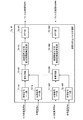
- FIG. 8 shows the speed-corresponding pulse compressors 7a- # l (1 ⁇ 1). The internal structure of l ⁇ L) is shown.
- the difference from the pulse compression unit 7- # l of the first embodiment is that a complex corresponding to a speed range is substituted for the complex window function multiplication circuits 74- # 1 to 74- # M of the first embodiment.
- the window function multiplication circuits 76- # 1 to 76- # M are provided. Since other configurations are the same as those in FIG. 2, the same reference numerals are given to corresponding portions, and the description thereof is omitted.
- the speed range corresponding complex window function multiplication circuits 76- # 1 to 76- # M calculate window functions for forming notches at unnecessary peak positions assuming a plurality of target speeds, and multiply the window functions by the multiplication circuit 73.
- This is a window function multiplication circuit that multiplies the output signals of # 1 to 73- # M.
- the signal processing unit 11a is composed of a speed-compatible signal processing board.
- the hardware configuration for realizing the speed-compatible pulse compression units 7a- # 1 to 7a- # L to the target detection unit 10 is shown in FIG. Since the configuration is the same as that of the processor 111, the memory 112, and the display 113, the description thereof is omitted here.
- a pulsed transmission wave is transmitted by the transmitter 1- # m (1 ⁇ m ⁇ M) and the transmission antenna 2- # m. Subsequent operations from the receiving antenna 4- # 1 on the receiving side to the multiplying circuits 73- # 1 to 73- # M in the speed corresponding pulse compression unit 7a- # l are the same as those in the first embodiment.
- Compressed signal spectrums z l, m, 1 ,..., Z l, m, N from the multiplier circuits 73- # 1 to 73- # M are the speed range corresponding complex window function multiplier circuits 76- # 1 to 76- # M.
- the speed window corresponding complex window function multiplication circuits 76- # 1 to 76- # M multiply the compressed signal spectrum by the complex window functions w m, 1 ... W m, N.
- the complex window function w m, 1 ... W m, N is calculated as an element of the vector w m calculated by the following equation (5).
- signals y ′ m, 1 ,..., Y ′ m, N represent the received signal spectral components of the transmission antenna- # m component of the target reflected wave affected by Doppler.
- k is a parameter corresponding to a plurality of target speeds.
- Received signal spectrum affected by Doppler y 'm, 1, ..., y' m, N is, for example transmitter 1- # a reference signal outputted from the m u m, 1, ..., u m, the N simulation signal u and Doppler shift by the following equation (6) 'm, k, 1, ..., u' m, k, is determined by FFT generates N.
- ⁇ is a transmission wavelength
- v k is a k-th target speed among a plurality of target speeds
- ⁇ t is an A / D conversion (transmission side A / D converters 3- # 1 to 3- # M and The sampling intervals of the receiving side A / D converters 6- # 1 to 6- # L) are shown.
- the window function used in ST6 of the flowchart of the first embodiment is replaced with the window function calculated by the equation (5).
- the window function for forming a notch at a position corresponding to the pulse width away from the main lobe is calculated assuming a plurality of target speeds, so that the target speed range in which the unwanted peak suppression effect can be expected can be expanded. .
- each of the L pulse compression units performs a Fourier transform process on the output signal of the reception A / D converter to generate a reception signal spectrum.
- IFFT Since to be composed of the suppression effect of unwanted peaks can be widened speed range of the target can be expected.
- FIG. 9 is a configuration diagram of the radar apparatus according to the third embodiment.
- the radar apparatus according to Embodiment 3 includes transmitters 1- # 1 to 1- # M, transmission antennas 2- # 1 to 2- # M, transmission side A / D converters 3- # 1 to 3- # M, Receiving antennas 4- # 1 to 4- # L, receivers 5- # 1 to 5- # L, receiving side A / D converters 6- # 1 to 6- # L, sidelobe corresponding pulse compression unit 7b- # 1-7b- # L, transmission DBF unit 8- # 1-8- # L, reception DBF unit 9, and target detection unit 10.
- the sidelobe-compatible pulse compressors 7b- # 1 to 7b- # L it is the same as that of the first embodiment shown in FIG. Omitted.
- the side lobe-compatible pulse compression units 7b- # 1 to 7b- # L are pulse compression units that suppress unnecessary peaks in correspondence with side lobes
- FIG. 10 shows the internal configuration.
- the difference from the pulse compression unit 7- # l of the first embodiment is that instead of the complex window function multiplication circuits 74- # 1 to 74- # M of the first embodiment, the sidelobe-compatible complex
- the window function multiplication circuits 77- # 1 to 77- # M are provided, and the other configurations are the same as those in FIG. 2, so the corresponding parts are denoted by the same reference numerals and the description thereof is omitted.
- the side lobe-compatible complex window function multiplication circuits 77- # 1 to 77- # M calculate a window function that forms a notch at the position of the unwanted peak including the side lobe level, and this window function is multiplied by the multiplication circuit 73- #.
- This is a window function multiplication circuit for multiplying output signals 1 to 73- # M.
- the signal processing unit 11b is composed of a sidelobe-compatible signal processing board, and the hardware configuration for realizing the sidelobe-compatible pulse compression units 7b- # 1 to 7b- # L to the target detection unit 10 is shown in FIG.
- a pulsed transmission wave is transmitted by the transmitter 1- # m (1 ⁇ m ⁇ M) and the transmission antenna 2- # m. Subsequent operations from the receiving antenna 4- # l on the receiving side to the multiplying circuits 73- # 1 to 73- # M in the sidelobe-compatible pulse compressor 7b- # l are the same as those in the first embodiment.
- Compressed signal spectrums z l, m, 1 ,..., Z l, m, N from the multiplier circuits 73- # 1 to 73- # M are sidelobe-compatible complex window function multiplier circuits 77- # 1 to 77- # M.
- the side lobe-compatible complex window function multiplying circuits 77- # 1 to 77- # M multiply the compressed signal spectrum by the complex window functions w m, 1 ... W m, N.
- the complex window function w m, 1 ... W m, N is calculated as an element of the vector w m calculated by the following equation (7).
- 1 is a 1-row N-column vector with all elements being 1
- I is a N-by-N unit vector
- ⁇ ′ (t) is a time domain coefficient corresponding to the pulse width
- side The lobe level also represents a weight that can be adjusted.
- FIG. 11 shows the relationship between the pulse width and the suppression region.
- the side lobe level, the notch width and the depth are controlled by the parameters ⁇ ′ 0 and ⁇ ′ 1 in FIG. 11, the width of the suppression region, the pass bandwidth, and the parameter ⁇ in Expression (7). Further, x ′ m, 1 ,..., X ′ m, N represents a received signal created in a pseudo manner.
- the window function used in ST6 of the flowchart of the first embodiment is replaced with the window function calculated by the equation (7). For this reason, by calculating a window function that forms a notch at a position corresponding to the pulse width away from the main lobe in correspondence with the side lobe level, both side lobe level reduction and unnecessary peak suppression can be expected.
- each of the L pulse compression units generates a received signal spectrum by performing a Fourier transform process on the output signal of the receiving A / D converter.
- M received signal FFT units, M reference signal FFT units for generating a reference signal spectrum by performing a Fourier transform process on the output signal of the transmitting A / D converter, and M received signal FFT units M multiplier circuits for generating a compressed signal spectrum from the output signal and the output signals of the M reference signal FFT units, and a window function for forming a notch at the position of the unnecessary peak including the side lobe level is calculated.
- the radar apparatus relates to a configuration that eliminates erroneous detection of a target due to occurrence of unnecessary peaks caused by Doppler, and is suitable for use in a MIMO (Multi-Input-Multi-Output) radar or the like. Yes.
- MIMO Multi-Input-Multi-Output
Landscapes
- Engineering & Computer Science (AREA)
- Remote Sensing (AREA)
- Radar, Positioning & Navigation (AREA)
- Physics & Mathematics (AREA)
- Computer Networks & Wireless Communication (AREA)
- General Physics & Mathematics (AREA)
- Electromagnetism (AREA)
- Spectroscopy & Molecular Physics (AREA)
- Radar Systems Or Details Thereof (AREA)
Abstract
Priority Applications (4)
| Application Number | Priority Date | Filing Date | Title |
|---|---|---|---|
| GB1815737.0A GB2563369B (en) | 2016-04-19 | 2016-04-19 | Radar device |
| US16/086,439 US10884114B2 (en) | 2016-04-19 | 2016-04-19 | Radar device |
| JP2018512672A JP6391888B2 (ja) | 2016-04-19 | 2016-04-19 | レーダ装置 |
| PCT/JP2016/062327 WO2017183097A1 (fr) | 2016-04-19 | 2016-04-19 | Dispositif de radar |
Applications Claiming Priority (1)
| Application Number | Priority Date | Filing Date | Title |
|---|---|---|---|
| PCT/JP2016/062327 WO2017183097A1 (fr) | 2016-04-19 | 2016-04-19 | Dispositif de radar |
Publications (1)
| Publication Number | Publication Date |
|---|---|
| WO2017183097A1 true WO2017183097A1 (fr) | 2017-10-26 |
Family
ID=60116640
Family Applications (1)
| Application Number | Title | Priority Date | Filing Date |
|---|---|---|---|
| PCT/JP2016/062327 Ceased WO2017183097A1 (fr) | 2016-04-19 | 2016-04-19 | Dispositif de radar |
Country Status (4)
| Country | Link |
|---|---|
| US (1) | US10884114B2 (fr) |
| JP (1) | JP6391888B2 (fr) |
| GB (1) | GB2563369B (fr) |
| WO (1) | WO2017183097A1 (fr) |
Cited By (5)
| Publication number | Priority date | Publication date | Assignee | Title |
|---|---|---|---|---|
| CN108226871A (zh) * | 2018-01-18 | 2018-06-29 | 西安电子工程研究所 | 基于毫米波避撞雷达的分集相控阵设计方法 |
| CN112292607A (zh) * | 2018-06-21 | 2021-01-29 | 罗伯特·博世有限公司 | 用于分析处理雷达信号的方法和设备 |
| CN112986919A (zh) * | 2021-02-10 | 2021-06-18 | 西南电子技术研究所(中国电子科技集团公司第十研究所) | 高密度dbf多路多目标信号处理装置 |
| JP2021527814A (ja) * | 2018-06-21 | 2021-10-14 | ロベルト・ボッシュ・ゲゼルシャフト・ミト・ベシュレンクテル・ハフツングRobert Bosch Gmbh | レーダ信号の評価のための装置および方法 |
| JP2022054455A (ja) * | 2020-09-25 | 2022-04-06 | インフィニオン テクノロジーズ アクチエンゲゼルシャフト | レーダーシステムのレーダー信号を処理する方法およびレーダーシステム |
Families Citing this family (5)
| Publication number | Priority date | Publication date | Assignee | Title |
|---|---|---|---|---|
| US11099267B2 (en) | 2018-12-18 | 2021-08-24 | Nxp Usa, Inc. | Extended doppler PMCW code division MIMO radar |
| US11054516B2 (en) * | 2018-12-18 | 2021-07-06 | Nxp Usa, Inc. | Extended doppler FMCW code division MIMO radar |
| CN111175750B (zh) * | 2020-01-20 | 2022-05-10 | 中国科学院电子学研究所 | 一种合成孔径雷达的成像方法及装置、设备、存储介质 |
| CN111208504A (zh) * | 2020-02-28 | 2020-05-29 | 成都汇蓉国科微系统技术有限公司 | 一种基于dsp的pd雷达波形配置方法及装置 |
| CN112649678B (zh) * | 2020-12-24 | 2024-05-28 | 广州山锋测控技术有限公司 | 天馈线测量方法、装置、天馈线测量器件和测试仪 |
Citations (4)
| Publication number | Priority date | Publication date | Assignee | Title |
|---|---|---|---|---|
| JP2009084791A (ja) * | 2007-09-27 | 2009-04-23 | Toto Ltd | 便器洗浄装置 |
| CN101452073B (zh) * | 2007-11-30 | 2011-12-28 | 清华大学 | 基于多发多收频分雷达的宽带信号合成方法 |
| JP2013068433A (ja) * | 2011-09-20 | 2013-04-18 | Fujitsu Ltd | 探知測距装置および探知測距方法 |
| JP2013088313A (ja) * | 2011-10-19 | 2013-05-13 | Japan Radio Co Ltd | レーダ装置 |
Family Cites Families (11)
| Publication number | Priority date | Publication date | Assignee | Title |
|---|---|---|---|---|
| EP1253441B1 (fr) * | 2000-01-28 | 2010-04-07 | Hitachi, Ltd. | Dispositif de mesure de distance |
| US7151484B2 (en) * | 2003-09-30 | 2006-12-19 | Kabushiki Kaisha Toshiba | Pulse compression processor |
| US7504989B2 (en) * | 2006-08-09 | 2009-03-17 | Fujitsu Ten Limited | On-vehicle radar device |
| EP2084555A2 (fr) * | 2006-10-31 | 2009-08-05 | Valeo Raytheon Systems, Inc. | Système et procédé pour un créer un signal d'alerte dans un système de détection |
| GB0701869D0 (en) * | 2007-01-31 | 2007-03-14 | Cambridge Consultants | Adaptive radar |
| JP4468402B2 (ja) * | 2007-04-19 | 2010-05-26 | 三菱電機株式会社 | レーダ装置 |
| JP5630034B2 (ja) * | 2010-03-04 | 2014-11-26 | 富士通株式会社 | レーダ装置及び目標探知方法 |
| US8305262B1 (en) * | 2010-03-08 | 2012-11-06 | Lockheed Martin Corporation | Mismatched pulse compression of nonlinear FM signal |
| US9250319B2 (en) * | 2010-10-21 | 2016-02-02 | Reutech Radar Systems (Proprietary) Limited | Floodlight radar system for detecting and locating moving targets in three dimensions |
| FR2987683B1 (fr) * | 2012-03-02 | 2016-11-11 | Thales Sa | Radar a faible probabilite d'interception |
| JP5972402B2 (ja) * | 2013-02-01 | 2016-08-17 | 三菱電機株式会社 | レーダ装置 |
-
2016
- 2016-04-19 JP JP2018512672A patent/JP6391888B2/ja active Active
- 2016-04-19 WO PCT/JP2016/062327 patent/WO2017183097A1/fr not_active Ceased
- 2016-04-19 US US16/086,439 patent/US10884114B2/en not_active Expired - Fee Related
- 2016-04-19 GB GB1815737.0A patent/GB2563369B/en active Active
Patent Citations (4)
| Publication number | Priority date | Publication date | Assignee | Title |
|---|---|---|---|---|
| JP2009084791A (ja) * | 2007-09-27 | 2009-04-23 | Toto Ltd | 便器洗浄装置 |
| CN101452073B (zh) * | 2007-11-30 | 2011-12-28 | 清华大学 | 基于多发多收频分雷达的宽带信号合成方法 |
| JP2013068433A (ja) * | 2011-09-20 | 2013-04-18 | Fujitsu Ltd | 探知測距装置および探知測距方法 |
| JP2013088313A (ja) * | 2011-10-19 | 2013-05-13 | Japan Radio Co Ltd | レーダ装置 |
Cited By (14)
| Publication number | Priority date | Publication date | Assignee | Title |
|---|---|---|---|---|
| CN108226871B (zh) * | 2018-01-18 | 2021-08-10 | 西安电子工程研究所 | 基于毫米波避撞雷达的分集相控阵设计方法 |
| CN108226871A (zh) * | 2018-01-18 | 2018-06-29 | 西安电子工程研究所 | 基于毫米波避撞雷达的分集相控阵设计方法 |
| US11598843B2 (en) | 2018-06-21 | 2023-03-07 | Robert Bosch Gmbh | Apparatus and method for analyzing radar signals |
| JP2021527814A (ja) * | 2018-06-21 | 2021-10-14 | ロベルト・ボッシュ・ゲゼルシャフト・ミト・ベシュレンクテル・ハフツングRobert Bosch Gmbh | レーダ信号の評価のための装置および方法 |
| JP2021527823A (ja) * | 2018-06-21 | 2021-10-14 | ロベルト・ボッシュ・ゲゼルシャフト・ミト・ベシュレンクテル・ハフツングRobert Bosch Gmbh | レーダ信号を評価するための方法および装置 |
| JP7221310B2 (ja) | 2018-06-21 | 2023-02-13 | ロベルト・ボッシュ・ゲゼルシャフト・ミト・ベシュレンクテル・ハフツング | レーダ信号を評価するための方法および装置 |
| JP7221309B2 (ja) | 2018-06-21 | 2023-02-13 | ロベルト・ボッシュ・ゲゼルシャフト・ミト・ベシュレンクテル・ハフツング | レーダ信号の評価のための装置および方法 |
| CN112292607A (zh) * | 2018-06-21 | 2021-01-29 | 罗伯特·博世有限公司 | 用于分析处理雷达信号的方法和设备 |
| US11835641B2 (en) | 2018-06-21 | 2023-12-05 | Robert Bosch Gmbh | Method and device for evaluating radar signals |
| CN112292607B (zh) * | 2018-06-21 | 2024-05-24 | 罗伯特·博世有限公司 | 用于分析处理雷达信号的方法和设备 |
| JP2022054455A (ja) * | 2020-09-25 | 2022-04-06 | インフィニオン テクノロジーズ アクチエンゲゼルシャフト | レーダーシステムのレーダー信号を処理する方法およびレーダーシステム |
| JP7759221B2 (ja) | 2020-09-25 | 2025-10-23 | インフィニオン テクノロジーズ アクチエンゲゼルシャフト | レーダーシステムのレーダー信号を処理する方法およびレーダーシステム |
| CN112986919A (zh) * | 2021-02-10 | 2021-06-18 | 西南电子技术研究所(中国电子科技集团公司第十研究所) | 高密度dbf多路多目标信号处理装置 |
| CN112986919B (zh) * | 2021-02-10 | 2023-08-18 | 西南电子技术研究所(中国电子科技集团公司第十研究所) | 高密度dbf多路多目标信号处理装置 |
Also Published As
| Publication number | Publication date |
|---|---|
| GB2563369B (en) | 2020-02-26 |
| GB2563369A (en) | 2018-12-12 |
| US20190101635A1 (en) | 2019-04-04 |
| US10884114B2 (en) | 2021-01-05 |
| GB201815737D0 (en) | 2018-11-14 |
| JP6391888B2 (ja) | 2018-09-19 |
| JPWO2017183097A1 (ja) | 2018-10-11 |
Similar Documents
| Publication | Publication Date | Title |
|---|---|---|
| JP6391888B2 (ja) | レーダ装置 | |
| JP6818541B2 (ja) | レーダ装置および測位方法 | |
| US8295393B2 (en) | Device and method for transmitting/receiving pulse signal | |
| JP2016151425A (ja) | レーダ装置 | |
| JP5301882B2 (ja) | パルス信号の送受信装置 | |
| EP1574966A2 (fr) | Procédé pour générer une fonction de pondération et dispositif de traitement du signal | |
| WO2012164898A1 (fr) | Dispositif radar | |
| JP5863443B2 (ja) | レーダ装置 | |
| WO2012140859A1 (fr) | Dispositif à radar | |
| WO2014092052A1 (fr) | Appareil radar | |
| JP5607424B2 (ja) | パルス圧縮装置、レーダ装置、パルス圧縮方法、およびパルス圧縮プログラム | |
| JP6494869B1 (ja) | レーダ装置 | |
| JP6296907B2 (ja) | レーダ装置及びそのレーダ信号処理方法 | |
| JP2011237338A (ja) | レーダ装置 | |
| JP2020016474A (ja) | レーダシステム及び信号処理方法 | |
| JP6373528B2 (ja) | レーダ装置 | |
| JP2013137268A (ja) | Fmcwレーダシステム | |
| JP6573748B2 (ja) | レーダ装置 | |
| JP5705066B2 (ja) | パッシブレーダ装置 | |
| JP7143146B2 (ja) | レーダシステム及びそのレーダ信号処理方法 | |
| JP2019120613A (ja) | レーダ装置、レーダ装置の制御方法、およびプログラム | |
| JP6351876B1 (ja) | レーダ装置 | |
| JP2013234943A (ja) | パルス圧縮装置 | |
| JP4784332B2 (ja) | パルスレーダ装置 | |
| JP2012233739A (ja) | レーダ装置 |
Legal Events
| Date | Code | Title | Description |
|---|---|---|---|
| ENP | Entry into the national phase |
Ref document number: 2018512672 Country of ref document: JP Kind code of ref document: A |
|
| ENP | Entry into the national phase |
Ref document number: 201815737 Country of ref document: GB Kind code of ref document: A Free format text: PCT FILING DATE = 20160419 |
|
| WWE | Wipo information: entry into national phase |
Ref document number: 1815737.0 Country of ref document: GB |
|
| NENP | Non-entry into the national phase |
Ref country code: DE |
|
| 121 | Ep: the epo has been informed by wipo that ep was designated in this application |
Ref document number: 16899371 Country of ref document: EP Kind code of ref document: A1 |
|
| 122 | Ep: pct application non-entry in european phase |
Ref document number: 16899371 Country of ref document: EP Kind code of ref document: A1 |