WO2017183106A1 - Manchon pour doigt destiné à un tensiomètre artériel - Google Patents
Manchon pour doigt destiné à un tensiomètre artériel Download PDFInfo
- Publication number
- WO2017183106A1 WO2017183106A1 PCT/JP2016/062350 JP2016062350W WO2017183106A1 WO 2017183106 A1 WO2017183106 A1 WO 2017183106A1 JP 2016062350 W JP2016062350 W JP 2016062350W WO 2017183106 A1 WO2017183106 A1 WO 2017183106A1
- Authority
- WO
- WIPO (PCT)
- Prior art keywords
- finger
- cuff
- movable
- base
- movable portion
- Prior art date
- Legal status (The legal status is an assumption and is not a legal conclusion. Google has not performed a legal analysis and makes no representation as to the accuracy of the status listed.)
- Ceased
Links
- 0 CCCC1(*)CC(CC*2N=N2)C*(C)CC1 Chemical compound CCCC1(*)CC(CC*2N=N2)C*(C)CC1 0.000 description 2
Images


Classifications
-
- A—HUMAN NECESSITIES
- A61—MEDICAL OR VETERINARY SCIENCE; HYGIENE
- A61B—DIAGNOSIS; SURGERY; IDENTIFICATION
- A61B5/00—Measuring for diagnostic purposes; Identification of persons
- A61B5/02—Detecting, measuring or recording for evaluating the cardiovascular system, e.g. pulse, heart rate, blood pressure or blood flow
- A61B5/021—Measuring pressure in heart or blood vessels
- A61B5/022—Measuring pressure in heart or blood vessels by applying pressure to close blood vessels, e.g. against the skin; Ophthalmodynamometers
- A61B5/02233—Occluders specially adapted therefor
- A61B5/02241—Occluders specially adapted therefor of small dimensions, e.g. adapted to fingers
-
- A—HUMAN NECESSITIES
- A61—MEDICAL OR VETERINARY SCIENCE; HYGIENE
- A61B—DIAGNOSIS; SURGERY; IDENTIFICATION
- A61B5/00—Measuring for diagnostic purposes; Identification of persons
- A61B5/02—Detecting, measuring or recording for evaluating the cardiovascular system, e.g. pulse, heart rate, blood pressure or blood flow
- A61B5/021—Measuring pressure in heart or blood vessels
- A61B5/022—Measuring pressure in heart or blood vessels by applying pressure to close blood vessels, e.g. against the skin; Ophthalmodynamometers
Definitions
- the present invention relates to a cuff for a finger blood pressure monitor.
- the sphygmomanometer cuff is connected to the main body of the sphygmomanometer and is wound around the site to be measured during blood pressure measurement.
- An air bag is provided inside the sphygmomanometer cuff. Air is supplied to the air bag to inflate the air bag, and the blood pressure at the measurement site is measured.
- a volume compensation method as a method capable of continuous measurement for each heartbeat. In order to realize this volume compensation method, it is necessary to control the arterial blood vessel at the measurement site from the body surface and keep the volume in the blood vessel constant.
- a finger is generally used as a measurement site suitable for this measurement method.
- a cuff is wrapped around the finger to measure the blood pressure in the finger artery.
- the finger vein may be excessively compressed and the finger may become congested.
- the continuous measurement of the blood pressure of the artery of the finger is performed by continuously controlling the pressurization and decompression on the finger.
- the measurement result may be adversely affected by the congestion of the finger.
- a base having a first curved portion along a part of the circumference of a finger to be measured, and a pivot part connected to the base, and another part around the finger. And at least one movable part that can be attached to the finger in a state where an opening is formed around the finger, and an adjustment part that can adjust an angle of the movable part with respect to the base part.
- a compression portion provided on at least a part of an inner peripheral portion formed along the periphery of the finger by the base, the movable portion, and the opening, and compressing a portion of the periphery of the finger.
- a cuff for a finger blood pressure monitor is provided.
- FIG. 1 is a diagram illustrating an example of a blood pressure measurement device according to the first embodiment.
- FIG. 2 is a diagram illustrating an example of a cuff according to the first embodiment.
- FIG. 3 is a diagram illustrating an example of the cuff according to the first embodiment.
- FIG. 4 is a diagram illustrating an example of the cuff according to the first embodiment.
- (A) and (B) of Drawing 5 are figures showing an example of a cuff concerning a 1st embodiment.
- FIG. 6 is a diagram illustrating an example of the cuff according to the first embodiment.
- FIG. 7 is a diagram illustrating an example of the cuff according to the first embodiment.
- (A) and (B) of Drawing 8 are figures showing an example of the cuff concerning a 1st embodiment.
- FIG. 10 is a diagram illustrating an example of a cuff according to the second embodiment.
- FIG. 12 is a diagram illustrating an example of a cuff according to the second embodiment.
- FIGS. 15A and 15B are diagrams illustrating an example of the cuff according to the third embodiment.
- FIG. 15A and 15B are diagrams illustrating an example of the cuff according to the third embodiment.
- FIG. 16 is a diagram illustrating an example of a cuff according to the third embodiment.
- (A) and (B) of Drawing 17 are figures showing an example of a cuff concerning a 3rd embodiment.
- 18A and 18B are diagrams illustrating an example of a cuff according to the third embodiment.
- FIG. 1 is a diagram illustrating an example of a blood pressure measurement device 1 according to the first embodiment.
- the blood pressure measurement device 1 is connected to a cuff 2 wound around a finger 5 of a person to be measured, a sphygmomanometer body 3 that continuously measures the blood pressure of the artery of the finger 5 via the cuff 2, and the cuff 2 and the sphygmomanometer body 3. Cable 4 to be provided.
- the blood pressure measurement device 1 may continuously measure the blood pressure of the artery of the finger 5 using a volume compensation method, or may continuously measure the blood pressure of the artery of the finger 5 using another method.
- the cuff 2 is an example of a cuff for a finger blood pressure monitor.
- the cuff 2 is attached to the finger 5 that is the object to be measured.
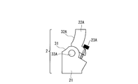
- the cuff 2 includes a base portion 21, movable portions 22A and 22B, adjustment screws 23A and 23B, an air bag 24, and rotating portions 33A and 33B. Further, the cuff 2 includes a detection unit that detects a pressure pulse wave of the artery of the finger 5 inside the base 21.
- the blood pressure monitor main body 3 includes a supply device that supplies air to the air bag 24 and a control device that controls the driving of the cuff 2.
- the control device of the sphygmomanometer main body 3 includes a CPU (Central Processing Unit) for performing various arithmetic processes, a memory for storing programs and various data, and the like.
- the memory is, for example, a ROM (Read Only Memory) and a RAM (Random Access Memory).
- the control device of the sphygmomanometer body 3 controls the pressure and supply amount of the air supplied to the air bladder 24 and acquires various data detected by the cuff 2.
- the base 21 has a curved portion 31 along a part of the periphery of the finger 5.
- the movable portion 22 ⁇ / b> A has a curved portion 32 ⁇ / b> A along a part of the periphery of the finger 5.
- the movable part 22 ⁇ / b> B has a curved part 32 ⁇ / b> B along a part of the periphery of the finger 5.
- the movable portion 22A is connected to the base portion 21 via the rotating portion 33A
- the movable portion 22B is connected to the base portion 21 via the rotating portion 33B.
- the movable portion 22A and the movable portion 22B are arranged so that the curved portion 32A of the movable portion 22A and the curved portion 32B of the movable portion 22B face each other.
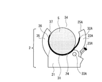
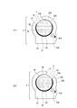
- FIG. 2 is a diagram illustrating an example of the cuff 2 according to the first embodiment.
- the adjusting screw 23A adjusts the angle ( ⁇ ) of the movable portion 22A with respect to the base portion 21.
- the adjusting screw 23A is an example of an adjusting unit.
- the adjusting screw 23A is connected to the base portion 21 and the movable portion 22A.
- the adjusting screw 23A passes through the base end portion of the movable portion 22A, and the tip end portion of the adjusting screw 23A is embedded in the base portion 21.
- a force is applied to the movable portion 22A, and the rotating portion 33A rotates to change the angle of the movable portion 22A with respect to the base portion 21.
- a force is applied to the movable portion 22A in a direction away from the base portion 21, and the rotating portion 33A rotates to reduce the angle of the movable portion 22A with respect to the base portion 21.
- a force is applied to the movable portion 22A in a direction approaching the base portion 21, and the rotating portion 33A rotates to increase the angle of the movable portion 22A with respect to the base portion 21.
- the adjusting screw 23B adjusts the angle ( ⁇ ) of the movable portion 22B with respect to the base portion 21.
- the adjusting screw 23B is an example of an adjusting unit.
- the adjusting screw 23B is connected to the base portion 21 and the movable portion 22A.
- the adjustment screw 23B penetrates the base end portion of the movable portion 22B, and the tip end portion of the adjustment screw 23B is embedded in the base portion 21.
- a force is applied to the movable portion 22B in a direction away from the base portion 21, and the rotating portion 33B rotates to reduce the angle of the movable portion 22B with respect to the base portion 21.
- a force is applied to the movable portion 22B in a direction approaching the base portion 21, and the rotating portion 33B rotates to increase the angle of the movable portion 22B with respect to the base portion 21.
- the angles of the movable portions 22A and 22B with respect to the base portion 21 are increased, and the cuff 2 is in an open state.
- the angles of the movable portions 22A and 22B with respect to the base portion 21 are reduced.
- the finger 5 is housed inside the cuff 2, and the angle of the movable parts 22 ⁇ / b> A and 22 ⁇ / b> B with respect to the base 21 is reduced, whereby the cuff 2 is fixed to the finger 5. Therefore, the cuff 2 is fixed to the finger 5 with the base 21 and the movable portions 22A and 22B being mounted around the finger 5 by tightening the adjusting screws 23A and 23B.
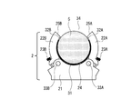
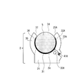
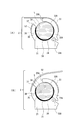
- FIG. 3 is a diagram illustrating an example of the cuff 2 according to the first embodiment.
- FIG. 3 shows a state in which the cuff 2 is attached to the finger 5 and the adjustment screws 23A and 23B are tightened to fix the cuff 2 to the finger 5.
- the tip portion 25A of the movable portion 22A and the tip portion 25B of the movable portion 22B are not in contact with each other, and an opening 34 is formed between the tip portion 25A of the movable portion 22A and the tip portion 25B of the movable portion 22B. . Therefore, the base 21 and the movable portions 22 ⁇ / b> A and 22 ⁇ / b> B are attached to the finger 5 with the opening 34 formed in a part of the periphery of the finger 5.
- the distance between the distal end portion 25A of the movable portion 22A and the distal end portion 25B of the movable portion 22B is, for example, about 5 mm, but is not limited to this value. There may be.
- the shapes of the movable portions 22A and 22B are symmetric with respect to the axis of the finger 5 (symmetric in the paper surface of FIG. 3). Accordingly, the shape of the bending portion 32A of the movable portion 22A and the shape of the bending portion 32B of the movable portion 22B are symmetric with respect to the axis of the finger 5. Therefore, the length of the bending portion 32A of the movable portion 22A and the length of the bending portion 32B of the movable portion 22B are the same.
- the air bag 24 is inflated by receiving supply of air from the blood pressure monitor main body 3 via the cable 4.
- the air bag 24 is an example of a compression part.
- the air bag 24 is provided on at least a part of the inner peripheral portion of the cuff 2 formed by the base portion 21, the movable portions 22 ⁇ / b> A and 22 ⁇ / b> B, and the opening portion 34.
- When the air bag 24 is inflated a part around the finger 5 is compressed.
- the finger 5 is pressurized and depressurized by controlling the air pressure and supply amount to the air bag 24. By repeatedly pressing and depressurizing the finger 5 alternately, the blood pressure of the artery of the finger 5 is continuously measured.
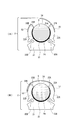
- FIG. 4 is a diagram illustrating an example of the cuff 2 according to the first embodiment.
- FIG. 4 shows a state where the cuff 2 is opened. The cuff 2 is removed from the finger 5 with the cuff 2 open.
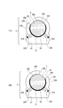
- FIG. 5 are diagrams showing an example of the cuff 2 according to the first embodiment.
- the shapes of the movable portions 22A and 22B are asymmetric with respect to the axis of the finger 5 (the left and right asymmetry in the paper surface of FIG. 5A).
- the shape of the curved portion 32A of the movable portion 22A and the shape of the curved portion 32B of the movable portion 22B are asymmetric with respect to the axis of the finger 5, and the length of the curved portion 32A of the movable portion 22A is the curved portion of the movable portion 22B. It is longer than the length of 32B.
- the cuff 2 Since the length of the curved portion 32A of the movable portion 22A is longer than the length of the curved portion 32B of the movable portion 22B, when the air bag 24 inflates and compresses a part around the finger 5, the cuff 2 is removed from the finger 5. Further detachment is further suppressed. Therefore, the cuff 2 can be more securely fixed to the finger 5.
- the shapes of the movable portions 22A and 22B are asymmetric with respect to the axis of the finger 5 (left and right asymmetry in the plane of FIG. 5B).
- the shape of the curved portion 32A of the movable portion 22A and the shape of the curved portion 32B of the movable portion 22B are asymmetric with respect to the axis of the finger 5, and the length of the curved portion 32B of the movable portion 22B is the curved portion of the movable portion 22A. Longer than 32A.
- the cuff 2 Since the length of the curved portion 32B of the movable portion 22B is longer than the length of the curved portion 32A of the movable portion 22A, when the air bag 24 inflates and compresses a part of the periphery of the finger 5, the cuff 2 is removed from the finger 5. Further detachment is further suppressed. Therefore, the cuff 2 can be more securely fixed to the finger 5.
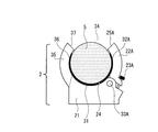
- FIG. 6 is a diagram illustrating an example of the cuff 2 according to the first embodiment. As shown in FIG. 6, the base 21 is provided with a protrusion 35 having the same shape as the movable part 22B shown in FIG.
- the base 21 and the protrusion 35 are integrally formed.
- the protrusion 35 has a curved portion 36 along a part of the periphery of the finger 5.
- the movable portion 22A and the protruding portion 35 are arranged so that the curved portion 32A of the movable portion 22A and the curved portion 36 of the protruding portion 35 face each other.
- FIG. 6 shows a state in which the cuff 2 is attached to the finger 5 and the adjustment screw 23A is tightened to fix the cuff 2 to the finger 5.
- the distal end portion 25A of the movable portion 22A and the distal end portion 37 of the projection 35 are not in contact with each other, and an opening 34 is formed between the distal end portion 25A of the movable portion 22A and the distal end portion 37 of the projection 35. . Therefore, the base 21, the protrusion 35, and the movable portion 22 ⁇ / b> A are attached to the finger 5 with the opening 34 formed in a part of the periphery of the finger 5.
- the shape of the curved portion 32A of the movable portion 22A and the shape of the curved portion 36 of the projection 35 are symmetric with respect to the axis of the finger 5 (right and left symmetrical on the paper surface of FIG. 6).
- the length of the bending portion 32A of the movable portion 22A is the same as the length of the bending portion 36 of the protrusion 35.
- the air bag 24 is provided on at least a part of the inner peripheral portion of the cuff 2 formed by the base portion 21, the movable portion 22 ⁇ / b> A, the opening portion 34, and the projection portion 35.
- the air bag 24 is inflated, a part around the finger 5 is compressed. Since the finger 5 is fixed to the cuff 2 by the adjusting screw 23 ⁇ / b> A, the cuff 2 is prevented from being detached from the finger 5 when the air bag 24 is inflated to compress a part around the finger 5.
- FIG. 7 is a diagram illustrating an example of the cuff 2 according to the first embodiment.
- FIG. 7 shows a state where the cuff 2 is opened. The cuff 2 is removed from the finger 5 with the cuff 2 open.
- FIG. 8A and 8B are diagrams illustrating an example of the cuff 2 according to the first embodiment.
- the shape of the curved portion 32A of the movable portion 22A and the shape of the curved portion 36 of the protrusion 35 are asymmetric with respect to the axis of the finger 5 (of FIG. 8A).
- the length of the curved portion 32A of the movable portion 22A is longer than the length of the curved portion 36 of the protruding portion 35.
- the length of the curved portion 32 ⁇ / b> A of the movable portion 22 ⁇ / b> A is longer than the length of the curved portion 36 of the protruding portion 35, when the air bag 24 inflates and compresses a part of the periphery of the finger 5, the cuff 2 is removed from the finger 5. Further detachment is further suppressed. Therefore, the cuff 2 can be more securely fixed to the finger 5.
- the shape of the curved portion 32A of the movable portion 22A and the shape of the curved portion 36 of the protrusion 35 are asymmetric with respect to the axis of the finger 5 (of FIG. 8B).
- the length of the curved portion 36 of the projection 35 is longer than the length of the curved portion 32A of the movable portion 22A. Since the length of the curved portion 36 of the protrusion 35 is longer than the length of the curved portion 32A of the movable portion 22A, when the air bag 24 inflates and compresses a part around the finger 5, the cuff 2 is removed from the finger 5. Further detachment is further suppressed. Therefore, the cuff 2 can be more securely fixed to the finger 5.
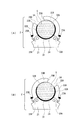
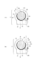
- FIGS. 9A and 9B are diagrams illustrating an example of the cuff 2 according to the first embodiment.
- the cuff 2 may support the finger 5 at three points (for example, a region surrounded by dotted lines 11A, 11B, and 11C).
- FIG. 9A shows a cuff including one base 21, a plurality of movable parts 22 (22A, 22B), a plurality of adjusting screws 23 (23A, 23B), and a plurality of rotating parts 33 (33A, 33B). 2 is an example. In the configuration example of the cuff 2 shown in FIG.
- FIG. 9A the finger 5 is supported by a predetermined portion of the base portion 21, a predetermined portion of the movable portion 22A, and a predetermined portion of the movable portion 22B.
- FIG. 9B shows an example of the cuff 2 including one base 21, one movable part 22 (22A), one adjusting screw 23 (23A), and one rotating part 33 (33A).
- the finger 5 is supported by a predetermined portion of the base portion 21, a predetermined portion of the protruding portion 35, and a predetermined portion of the movable portion 22 ⁇ / b> A.
- the air bag 24 is not shown, but the cuff 2 may support the finger 5 at three points via the air bag 24.
- FIG. 10 is a diagram illustrating an example of the cuff 2 according to the second embodiment.
- the cuff 2 includes a base portion 21, movable portions 22A and 22B, an air bag 24, rotating portions 33A and 33B, and adjustment springs 41A and 42B.
- FIG. 10 shows a state in which the cuff 2 is attached to the finger 5 and the cuff 2 is fixed to the finger 5.
- the adjustment spring 41A adjusts the angle ( ⁇ ) of the movable portion 22A with respect to the base portion 21.
- the adjustment spring 41A is an example of an adjustment unit.
- the adjustment spring 41A is an example of an adjustment elastic body.
- the adjustment spring 41A is, for example, a spring spring or a leaf spring. As shown in FIG. 10, the adjustment spring 41A is disposed between the base portion 21 and the base end portion of the movable portion 22A, and is connected to the base portion 21 and the base end portions of the movable portion 22A.
- the adjustment spring 41A extends, a force is applied to the movable portion 22A in a direction away from the base portion 21, and the rotating portion 33A rotates to reduce the angle of the movable portion 22A with respect to the base portion 21.
- the adjustment spring 41B adjusts the angle ( ⁇ ) of the movable portion 22B with respect to the base portion 21.
- the adjustment spring 41B is an example of an adjustment unit.
- the adjustment spring 41B is an example of an adjustment elastic body.
- the adjustment spring 41B is, for example, a spring spring or a leaf spring. As shown in FIG. 10, the adjustment spring 41B is disposed between the base portion 21 and the base end portion of the movable portion 22B, and is connected to the base portion 21 and the base end portions of the movable portion 22B.
- the adjustment spring 41B contracts, a force is applied to the movable portion 22B in a direction approaching the base portion 21, and the rotating portion 33B rotates to increase the angle of the movable portion 22B with respect to the base portion 21.
- the cuff 2 When the cuff 2 is attached to the finger 5, by inserting the finger 5 into the gap between the movable portions 22A and 22B, the angle of the movable portions 22A and 22B with respect to the base portion 21 is increased, and the cuff 2 is opened. Become. When the finger 5 is housed inside the cuff 2, the angles of the movable parts 22 ⁇ / b> A and 22 ⁇ / b> B with respect to the base part 21 become small. The finger 5 is housed inside the cuff 2, and the angle of the movable parts 22 ⁇ / b> A and 22 ⁇ / b> B with respect to the base 21 is reduced, whereby the cuff 2 is fixed to the finger 5. Accordingly, the cuff 2 is fixed to the finger 5 in a state where the base 21 and the movable portions 22A and 22B are mounted around the finger 5.
- the tip portion 25A of the movable portion 22A and the tip portion 25B of the movable portion 22B are not in contact with each other, and an opening 34 is formed between the tip portion 25A of the movable portion 22A and the tip portion 25B of the movable portion 22B. . Therefore, the base 21 and the movable portions 22 ⁇ / b> A and 22 ⁇ / b> B are attached to the finger 5 with the opening 34 formed in a part of the periphery of the finger 5.
- the shapes of the movable portions 22 ⁇ / b> A and 22 ⁇ / b> B are symmetric with respect to the axis of the finger 5 (right and left symmetrical on the paper surface of FIG. 10).
- the shape of the bending portion 32A of the movable portion 22A and the shape of the bending portion 32B of the movable portion 22B are symmetric with respect to the axis of the finger 5. Therefore, the length of the bending portion 32A of the movable portion 22A and the length of the bending portion 32B of the movable portion 22B are the same.
- the air bag 24 is provided on at least a part of the inner peripheral portion of the cuff 2 formed by the base portion 21, the movable portions 22 ⁇ / b> A and 22 ⁇ / b> B, and the opening portion 34.
- the air bag 24 When the air bag 24 is inflated, a part around the finger 5 is compressed. Since the finger 5 is fixed to the cuff 2 by the adjustment springs 41 ⁇ / b> A and 41 ⁇ / b> B, the cuff 2 is prevented from being detached from the finger 5 when the air bag 24 is inflated and compresses a part around the finger 5. .
- FIG. 11 are diagrams illustrating an example of the cuff 2 according to the second embodiment.
- the shapes of the movable portions 22 ⁇ / b> A and 22 ⁇ / b> B are asymmetric with respect to the axis of the finger 5 (left and right asymmetry in the paper surface of FIG. 11A).
- the shape of the curved portion 32A of the movable portion 22A and the shape of the curved portion 32B of the movable portion 22B are asymmetric with respect to the axis of the finger 5, and the length of the curved portion 32A of the movable portion 22A is the curved portion of the movable portion 22B. It is longer than the length of 32B.
- the cuff 2 Since the length of the curved portion 32A of the movable portion 22A is longer than the length of the curved portion 32B of the movable portion 22B, when the air bag 24 inflates and compresses a part around the finger 5, the cuff 2 is removed from the finger 5. Further detachment is further suppressed. Therefore, the cuff 2 can be more securely fixed to the finger 5.
- the shapes of the movable portions 22A and 22B are asymmetric with respect to the axis of the finger 5 (the left and right asymmetry in the paper surface of FIG. 11 (B)).
- the shape of the curved portion 32A of the movable portion 22A and the shape of the curved portion 32B of the movable portion 22B are asymmetric with respect to the axis of the finger 5, and the length of the curved portion 32B of the movable portion 22B is the curved portion of the movable portion 22A. Longer than 32A.
- the cuff 2 Since the length of the curved portion 32B of the movable portion 22B is longer than the length of the curved portion 32A of the movable portion 22A, when the air bag 24 inflates and compresses a part of the periphery of the finger 5, the cuff 2 is removed from the finger 5. Further detachment is further suppressed. Therefore, the cuff 2 can be more securely fixed to the finger 5.
- FIG. 12 is a diagram illustrating an example of the cuff 2 according to the second embodiment. As shown in FIG.
- the base portion 21 is provided with a projection 35 having the same shape as the movable portion 22B shown in FIG.
- the base 21 and the protrusion 35 are integrally formed.
- the protrusion 35 has a curved portion 36 along a part of the periphery of the finger 5.
- the movable portion 22A and the protruding portion 35 are arranged so that the curved portion 32A of the movable portion 22A and the curved portion 36 of the protruding portion 35 face each other.
- FIG. 12 shows a state in which the cuff 2 is attached to the finger 5 and the cuff 2 is fixed to the finger 5.
- the distal end portion 25A of the movable portion 22A and the distal end portion 37 of the projection 35 are not in contact with each other, and an opening 34 is formed between the distal end portion 25A of the movable portion 22A and the distal end portion 37 of the projection 35. . Therefore, the base 21, the protrusion 35, and the movable portion 22 ⁇ / b> A are attached to the finger 5 with the opening 34 formed in a part of the periphery of the finger 5.
- the shape of the curved portion 32A of the movable portion 22A and the shape of the curved portion 36 of the projection 35 are symmetric with respect to the axis of the finger 5 (right and left symmetrical on the paper surface of FIG. 12).
- the length of the bending portion 32A of the movable portion 22A is the same as the length of the bending portion 36 of the protrusion 35.
- the air bag 24 is provided on at least a part of the inner peripheral portion of the cuff 2 formed by the base portion 21, the movable portion 22 ⁇ / b> A, the opening portion 34, and the projection portion 35.
- the air bag 24 is inflated, a part around the finger 5 is compressed.
- the adjustment spring 41 ⁇ / b> A By fixing the cuff 2 to the finger 5 by the adjustment spring 41 ⁇ / b> A, the cuff 2 is prevented from being detached from the finger 5 when the air bladder 24 is inflated to compress a part around the finger 5.
- FIG. 13 are diagrams illustrating an example of the cuff 2 according to the second embodiment.
- the shape of the curved portion 32A of the movable portion 22A and the shape of the curved portion 36 of the protrusion 35 are asymmetric with respect to the axis of the finger 5 (of FIG. 13A).
- the length of the curved portion 32A of the movable portion 22A is longer than the length of the curved portion 36 of the protruding portion 35.
- the length of the curved portion 32 ⁇ / b> A of the movable portion 22 ⁇ / b> A is longer than the length of the curved portion 36 of the protruding portion 35, when the air bag 24 inflates and compresses a part of the periphery of the finger 5, the cuff 2 is removed from the finger 5. Further detachment is further suppressed. Therefore, the cuff 2 can be more securely fixed to the finger 5.
- the shape of the curved portion 32A of the movable portion 22A and the shape of the curved portion 36 of the protrusion 35 are asymmetric with respect to the axis of the finger 5 (of FIG. 13B).
- the length of the curved portion 36 of the projection 35 is longer than the length of the curved portion 32A of the movable portion 22A. Since the length of the curved portion 36 of the protrusion 35 is longer than the length of the curved portion 32A of the movable portion 22A, when the air bag 24 inflates and compresses a part around the finger 5, the cuff 2 is removed from the finger 5. Further detachment is further suppressed. Therefore, the cuff 2 can be more securely fixed to the finger 5.
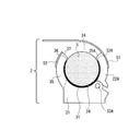
- FIGS. 14 to 18 A third embodiment will be described with reference to FIGS. 14 to 18. Since the blood pressure monitor main body 3 and the cable 4 included in the blood pressure measurement device 1 according to the third embodiment are the same as those in the first embodiment, the description thereof is omitted. The same components as those of the first embodiment are denoted by the same reference numerals as those of the first embodiment, and the description thereof is omitted. 14A and 14B are diagrams illustrating an example of the cuff 2 according to the third embodiment.
- the cuff 2 includes a base portion 21, movable portions 22 ⁇ / b> A and 22 ⁇ / b> B, an air bag 24, rotating portions 33 ⁇ / b> A and 33 ⁇ / b> B, and adjustment band members 51 and 52.
- FIG. 14A shows a state in which the cuff 2 is attached to the finger 5.
- FIG. 14B shows a state in which the cuff 2 is attached to the finger 5 and the cuff 2 is fixed to the finger 5.
- the adjustment band member 51 adjusts the angle ( ⁇ ) of the movable portion 22A with respect to the base portion 21.
- the adjustment band member 52 adjusts the angle ( ⁇ ) of the movable portion 22B with respect to the base portion 21.
- the adjustment band members 51 and 52 are an example of an adjustment unit.
- the adjustment band members 51 and 52 are, for example, adjustment belts or hook-and-loop fasteners. As shown in FIGS. 14A and 14B, one end of the adjustment band member 51 is provided on the outer peripheral surface of the movable portion 22A, and the adjustment band member 52 is the outer peripheral surface of the movable portion 22B. Is provided.
- the length of the adjustment band member 51 is longer than the length of the adjustment band member 52.
- the other end of the adjustment band member 51 is detachably fixed to the adjustment band member 52. Any position at the other end of the adjustment band member 51 can be attached to the adjustment band member 52.
- the cuff 2 is attached to the finger 5
- the other end of the adjustment band member 51 is removed from the adjustment band member 52, so that the cuff 2 is opened.
- the finger 5 is housed inside the cuff 2 with the cuff 2 open.
- the finger 5 is housed inside the cuff 2, and the angle of the movable parts 22 ⁇ / b> A and 22 ⁇ / b> B with respect to the base 21 is reduced, whereby the cuff 2 is fixed to the finger 5. Accordingly, the cuff 2 is fixed to the finger 5 in a state where the base 21 and the movable portions 22A and 22B are mounted around the finger 5.
- the tip portion 25A of the movable portion 22A and the tip portion 25B of the movable portion 22B are not in contact with each other, and an opening 34 is formed between the tip portion 25A of the movable portion 22A and the tip portion 25B of the movable portion 22B. . Therefore, the movable portions 22 ⁇ / b> A and 22 ⁇ / b> B are attached to the finger 5 with the opening 34 formed in a part of the periphery of the finger 5. As shown in FIG. 14B, when the other end of the adjustment band member 51 is attached to the adjustment band member 52, a part of the adjustment band member 51 covers the opening 34. In the cuff 2 shown in FIGS.
- the shapes of the movable portions 22A and 22B are symmetric with respect to the axis of the finger 5 (symmetrical in the plane of FIG. 14A and FIG. 14B). It is. Accordingly, the shape of the bending portion 32A of the movable portion 22A and the shape of the bending portion 32B of the movable portion 22B are symmetric with respect to the axis of the finger 5. Therefore, the length of the bending portion 32A of the movable portion 22A and the length of the bending portion 32B of the movable portion 22B are the same.
- the air bag 24 is provided on at least a part of the inner peripheral portion of the cuff 2 formed by the base portion 21, the movable portions 22 ⁇ / b> A and 22 ⁇ / b> B, and the opening portion 34.
- the air bag 24 is inflated, a part around the finger 5 is compressed. Since the finger 5 is fixed to the cuff 2 by the adjustment band members 51 and 52, the cuff 2 is prevented from being detached from the finger 5 when the air bag 24 is inflated and compresses a part around the finger 5.
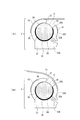
- FIGS. 15A and 15B are diagrams illustrating an example of the cuff 2 according to the third embodiment.
- the shapes of the movable parts 22A and 22B are asymmetric with respect to the axis of the finger 5 (the left and right asymmetries in the planes of FIGS. 15A and 15B). It is.
- the shape of the curved portion 32A of the movable portion 22A and the shape of the curved portion 32B of the movable portion 22B are asymmetric with respect to the axis of the finger 5, and the length of the curved portion 32B of the movable portion 22B is the curved portion of the movable portion 22A. Longer than 32A.
- the cuff 2 Since the length of the curved portion 32B of the movable portion 22B is longer than the length of the curved portion 32A of the movable portion 22A, when the air bag 24 inflates and compresses a part of the periphery of the finger 5, the cuff 2 is removed from the finger 5. Further detachment is further suppressed. Therefore, the cuff 2 can be more securely fixed to the finger 5.
- the adjustment band member 51 is provided on the outer peripheral surface of the movable portion 22A, and one end of the adjustment band member 52 is provided on the outer peripheral surface of the movable portion 22B. Yes.
- the length of the adjustment band member 52 is longer than the length of the adjustment band member 51.
- the other end of the adjustment band member 52 is detachably fixed to the adjustment band member 51.
- An arbitrary position at the other end of the adjustment band member 52 can be attached to the adjustment band member 51.
- the angles of the movable portions 22A and 22B with respect to the base portion 21 are reduced.
- the finger 5 is housed inside the cuff 2, and the angle of the movable parts 22 ⁇ / b> A and 22 ⁇ / b> B with respect to the base 21 is reduced, whereby the cuff 2 is fixed to the finger 5. Accordingly, the cuff 2 is fixed to the finger 5 in a state where the base 21 and the movable portions 22A and 22B are mounted around the finger 5.
- one end of the adjustment band member 51 is provided on the outer peripheral surface of the movable portion 22A, and the adjustment band member 52 is provided on the outer peripheral surface of the movable portion 22B. Yes.
- the length of the adjustment band member 51 is longer than the length of the adjustment band member 52.
- the other end of the adjustment band member 51 is detachably fixed to the adjustment band member 52. Any position at the other end of the adjustment band member 51 can be attached to the adjustment band member 52.
- the cuff 2 is attached to the finger 5
- the other end of the adjustment band member 51 is removed from the adjustment band member 52, so that the cuff 2 is opened.
- the finger 5 is housed inside the cuff 2 with the cuff 2 open.
- the angles of the movable portions 22A and 22B with respect to the base portion 21 are reduced.
- the finger 5 is housed inside the cuff 2, and the angle of the movable parts 22 ⁇ / b> A and 22 ⁇ / b> B with respect to the base 21 is reduced, whereby the cuff 2 is fixed to the finger 5. Accordingly, the cuff 2 is fixed to the finger 5 in a state where the base 21 and the movable portions 22A and 22B are mounted around the finger 5.
- FIG. 16 is a diagram illustrating an example of the cuff 2 according to the third embodiment. As shown in FIG. 16, the base 21 is provided with a protrusion 35 having the same shape as the movable part 22B shown in FIG.
- the base 21 and the protrusion 35 are integrally formed.
- the protrusion 35 has a curved portion 36 along a part of the periphery of the finger 5.
- the movable portion 22A and the protruding portion 35 are arranged so that the curved portion 32A of the movable portion 22A and the curved portion 36 of the protruding portion 35 face each other.
- FIG. 16 shows a state in which the cuff 2 is worn on the finger 5.
- the distal end portion 25A of the movable portion 22A and the distal end portion 37 of the projection 35 are not in contact with each other, and an opening 34 is formed between the distal end portion 25A of the movable portion 22A and the distal end portion 37 of the projection 35. . Therefore, the base 21, the protrusion 35, and the movable portion 22 ⁇ / b> A are attached to the finger 5 with the opening 34 formed in a part of the periphery of the finger 5.
- the shape of the curved portion 32A of the movable portion 22A and the shape of the curved portion 36 of the projection 35 are symmetric with respect to the axis of the finger 5 (right and left symmetrical on the paper surface of FIG. 16).
- the length of the bending portion 32A of the movable portion 22A is the same as the length of the bending portion 36 of the protrusion 35.
- the air bag 24 is provided on at least a part of the inner peripheral portion of the cuff 2 formed by the base portion 21, the movable portion 22 ⁇ / b> A, the opening portion 34, and the projection portion 35.
- the air bag 24 is inflated, a part around the finger 5 is compressed.
- the cuff 2 is prevented from being detached from the finger 5 when the air bag 24 is inflated to compress a part around the finger 5. Is done.
- FIGS. 17A and 17B are diagrams illustrating an example of the cuff 2 according to the third embodiment.
- the shape of the bending portion 32A of the movable portion 22A and the shape of the bending portion 36 of the protrusion 35 are asymmetric with respect to the axis of the finger 5 (see FIG. 17).
- (A) and (B) are laterally asymmetric), and the length of the curved portion 36 of the projection 35 is longer than the length of the curved portion 32A of the movable portion 22A.
- the cuff 2 Since the length of the curved portion 36 of the protrusion 35 is longer than the length of the curved portion 32A of the movable portion 22A, when the air bag 24 inflates and compresses a part around the finger 5, the cuff 2 is removed from the finger 5. Further detachment is further suppressed. Therefore, the cuff 2 can be more securely fixed to the finger 5.
- the adjustment band member 51 is provided on the outer peripheral surface of the movable portion 22A, and one end of the adjustment band member 52 is provided on the outer peripheral surface of the protrusion 35. Yes.
- the length of the adjustment band member 52 is longer than the length of the adjustment band member 51.
- the other end of the adjustment band member 52 is detachably fixed to the adjustment band member 51.
- An arbitrary position at the other end of the adjustment band member 52 can be attached to the adjustment band member 51.
- the angle of the movable portion 22A with respect to the base 21 is reduced.
- the finger 5 is accommodated inside the cuff 2, and the angle of the movable portion 22 ⁇ / b> A with respect to the base portion 21 is reduced, whereby the cuff 2 is fixed to the finger 5. Therefore, the cuff 2 is fixed to the finger 5 with the base 21, the movable portion 22 ⁇ / b> A, and the projection 35 attached around the finger 5.
- one end of the adjustment band member 51 is provided on the outer peripheral surface of the movable portion 22A, and the adjustment band member 52 is provided on the outer peripheral surface of the protrusion 35. Yes.
- the length of the adjustment band member 51 is longer than the length of the adjustment band member 52.
- the other end of the adjustment band member 51 is detachably fixed to the adjustment band member 52. Any position at the other end of the adjustment band member 51 can be attached to the adjustment band member 52.
- the angle of the movable portion 22A with respect to the base 21 is reduced.
- the finger 5 is accommodated inside the cuff 2, and the angle of the movable portion 22 ⁇ / b> A with respect to the base portion 21 is reduced, whereby the cuff 2 is fixed to the finger 5. Therefore, the cuff 2 is fixed to the finger 5 with the base 21, the movable portion 22 ⁇ / b> A, and the projection 35 attached around the finger 5.
- FIGS. 18A and 18B are diagrams illustrating an example of the cuff 2 according to the third embodiment.
- the shape of the bending portion 32A of the movable portion 22A and the shape of the bending portion 36 of the protrusion 35 are asymmetric with respect to the axis of the finger 5 (see FIG. 18).
- the length of the curved portion 32A of the movable portion 22A is longer than the length of the curved portion 36 of the projecting portion 35.
- the length of the curved portion 32 ⁇ / b> A of the movable portion 22 ⁇ / b> A is longer than the length of the curved portion 36 of the protruding portion 35, when the air bag 24 inflates and compresses a part of the periphery of the finger 5, the cuff 2 is removed from the finger 5. Further detachment is further suppressed. Therefore, the cuff 2 can be more securely fixed to the finger 5.
- one end of the adjustment band member 51 is provided on the outer peripheral surface of the movable portion 22A, and the adjustment band member 52 is provided on the outer peripheral surface of the protrusion 35. Yes.
- the length of the adjustment band member 51 is longer than the length of the adjustment band member 52.
- the other end of the adjustment band member 51 is detachably fixed to the adjustment band member 52. Any position at the other end of the adjustment band member 51 can be attached to the adjustment band member 52.
- the angle of the movable portion 22A with respect to the base 21 is reduced.
- the finger 5 is accommodated inside the cuff 2, and the angle of the movable portion 22 ⁇ / b> A with respect to the base portion 21 is reduced, whereby the cuff 2 is fixed to the finger 5. Therefore, the cuff 2 is fixed to the finger 5 with the base 21, the movable portion 22 ⁇ / b> A, and the projection 35 attached around the finger 5.
- the adjustment band member 51 is provided on the outer peripheral surface of the movable portion 22A, and one end portion of the adjustment band member 52 is provided on the outer peripheral surface of the protrusion portion 35. Yes.
- the length of the adjustment band member 52 is longer than the length of the adjustment band member 51.
- the other end of the adjustment band member 52 is detachably fixed to the adjustment band member 51.
- An arbitrary position at the other end of the adjustment band member 52 can be attached to the adjustment band member 51.
- the angle of the movable portion 22A with respect to the base 21 is reduced.
- the finger 5 is accommodated inside the cuff 2, and the angle of the movable portion 22 ⁇ / b> A with respect to the base portion 21 is reduced, whereby the cuff 2 is fixed to the finger 5. Therefore, the cuff 2 is fixed to the finger 5 with the base 21, the movable portion 22 ⁇ / b> A, and the projection 35 attached around the finger 5.
- the cuff 2 According to the cuff 2 according to each embodiment, it is possible to suppress the congestion of the finger 5 when continuously measuring the blood pressure of the artery of the finger 5 and improve the accuracy of the measurement result.
- the angles of the movable portions 22A and 22B with respect to the base portion 21 can be adjusted using the adjusting screws 23A and 23B.
- the angles of the movable portions 22A and 22B with respect to the base portion 21 can be adjusted using the adjustment springs 41A and 41B.
- the angles of the movable portions 22A and 22B relative to the base portion 21 can be adjusted using the adjustment band members 51 and 52.
- the tightness of the cuff 2 can be adjusted according to the thickness of the finger 5, so that even if the thickness of the finger 5 is different for each individual, the finger 5 The blood pressure of the artery can be measured.
- the cuff 2 according to the second embodiment when the finger 5 is accommodated in the cuff 2, the angles of the movable portions 22A and 22B with respect to the base portion 21 change, and accordingly, according to the first and third embodiments. Compared with the cuff 2, the angle of the movable portions 22A and 22B with respect to the base portion 21 can be easily adjusted.
Landscapes
- Health & Medical Sciences (AREA)
- Life Sciences & Earth Sciences (AREA)
- Vascular Medicine (AREA)
- Cardiology (AREA)
- Biomedical Technology (AREA)
- Molecular Biology (AREA)
- Physiology (AREA)
- Biophysics (AREA)
- Pathology (AREA)
- Engineering & Computer Science (AREA)
- Ophthalmology & Optometry (AREA)
- Heart & Thoracic Surgery (AREA)
- Medical Informatics (AREA)
- Physics & Mathematics (AREA)
- Surgery (AREA)
- Animal Behavior & Ethology (AREA)
- General Health & Medical Sciences (AREA)
- Public Health (AREA)
- Veterinary Medicine (AREA)
- Dentistry (AREA)
- Measuring Pulse, Heart Rate, Blood Pressure Or Blood Flow (AREA)
Abstract
La présente invention concerne un manchon pour doigt destiné à un tensiomètre artériel, ledit manchon comprenant : une partie de base ayant une première partie incurvée qui s'étend le long d'une partie autour d'un doigt à mesurer ; au moins une partie mobile qui est reliée à la partie de base par une partie pivot, qui présente une seconde partie incurvée qui s'étend le long d'une autre partie autour du doigt, et qui peut être montée sur le doigt avec une ouverture formée autour du doigt ; une partie de réglage qui est apte à régler l'angle de la partie mobile par rapport à la partie de base ; et une partie de compression qui est disposée sur au moins une partie d'une partie périphérique interne qui est formée par la partie de base, la partie mobile et l'ouverture de manière à s'étendre autour du doigt et à comprimer une partie autour du doigt.
Priority Applications (3)
| Application Number | Priority Date | Filing Date | Title |
|---|---|---|---|
| JP2018512680A JP6791244B2 (ja) | 2016-04-19 | 2016-04-19 | 指用血圧計用カフ |
| PCT/JP2016/062350 WO2017183106A1 (fr) | 2016-04-19 | 2016-04-19 | Manchon pour doigt destiné à un tensiomètre artériel |
| US16/165,562 US20190053724A1 (en) | 2016-04-19 | 2018-10-19 | Sphygmomanometer cuff for finger |
Applications Claiming Priority (1)
| Application Number | Priority Date | Filing Date | Title |
|---|---|---|---|
| PCT/JP2016/062350 WO2017183106A1 (fr) | 2016-04-19 | 2016-04-19 | Manchon pour doigt destiné à un tensiomètre artériel |
Related Child Applications (1)
| Application Number | Title | Priority Date | Filing Date |
|---|---|---|---|
| US16/165,562 Continuation US20190053724A1 (en) | 2016-04-19 | 2018-10-19 | Sphygmomanometer cuff for finger |
Publications (1)
| Publication Number | Publication Date |
|---|---|
| WO2017183106A1 true WO2017183106A1 (fr) | 2017-10-26 |
Family
ID=60115748
Family Applications (1)
| Application Number | Title | Priority Date | Filing Date |
|---|---|---|---|
| PCT/JP2016/062350 Ceased WO2017183106A1 (fr) | 2016-04-19 | 2016-04-19 | Manchon pour doigt destiné à un tensiomètre artériel |
Country Status (3)
| Country | Link |
|---|---|
| US (1) | US20190053724A1 (fr) |
| JP (1) | JP6791244B2 (fr) |
| WO (1) | WO2017183106A1 (fr) |
Cited By (2)
| Publication number | Priority date | Publication date | Assignee | Title |
|---|---|---|---|---|
| CN109091122A (zh) * | 2018-07-17 | 2018-12-28 | 韩明芬 | 一种麻醉科用生命体征监测装置 |
| WO2023232856A1 (fr) | 2022-06-01 | 2023-12-07 | iNDTact GmbH | Dispositif de mesure de la pression artérielle |
Families Citing this family (1)
| Publication number | Priority date | Publication date | Assignee | Title |
|---|---|---|---|---|
| CN118557160B (zh) * | 2024-06-25 | 2025-02-14 | 上海贝瑞电子科技有限公司 | 一种监测呼吸状态的睡眠监测仪 |
Citations (3)
| Publication number | Priority date | Publication date | Assignee | Title |
|---|---|---|---|---|
| JPS5458987A (en) * | 1977-10-11 | 1979-05-12 | Sacks Alvin Howard | Device for measuring blood pressure |
| JPH0541504U (ja) * | 1991-11-15 | 1993-06-08 | 有限会社谷田部ビニール工業 | 指 帯 |
| JP2000166884A (ja) * | 1998-12-02 | 2000-06-20 | Nec Medical Systems Kk | 指動脈血圧計用カフブロック |
Family Cites Families (10)
| Publication number | Priority date | Publication date | Assignee | Title |
|---|---|---|---|---|
| US4202347A (en) * | 1975-06-05 | 1980-05-13 | Sacks Alvin H | Method and apparatus for determining blood pressure |
| US4331155A (en) * | 1977-10-11 | 1982-05-25 | Sacks Alvin H | Digital cuff apparatus for determining blood pressure without use of a stethoscope |
| DE3004011A1 (de) * | 1980-02-04 | 1981-08-13 | Philips Patentverwaltung Gmbh, 2000 Hamburg | Blutdruck-messvorrichtung |
| US4790325A (en) * | 1985-11-25 | 1988-12-13 | Lee Arnold S | Automatic arterial blood pressure recorder |
| EP1404215B1 (fr) * | 2001-06-20 | 2007-08-15 | Purdue Research Foundation | Coussinet compressif eclairant une partie du corps pour la mesure optique non invasive de parametres sanguins |
| JP3818220B2 (ja) * | 2002-06-03 | 2006-09-06 | オムロンヘルスケア株式会社 | 手首式血圧計用カフ |
| JP4595449B2 (ja) * | 2004-09-02 | 2010-12-08 | オムロンヘルスケア株式会社 | 血圧計用カフ |
| KR100657959B1 (ko) * | 2005-05-03 | 2006-12-14 | 삼성전자주식회사 | 커프의 점탄성 특성을 이용한 혈압계 및 이를 구비한이동형 단말기 |
| JP2008099890A (ja) * | 2006-10-19 | 2008-05-01 | Sharp Corp | 生体情報測定装置 |
| TWM371529U (en) * | 2009-08-12 | 2010-01-01 | Quanta Comp Inc | Blood pressure monitor |
-
2016
- 2016-04-19 WO PCT/JP2016/062350 patent/WO2017183106A1/fr not_active Ceased
- 2016-04-19 JP JP2018512680A patent/JP6791244B2/ja active Active
-
2018
- 2018-10-19 US US16/165,562 patent/US20190053724A1/en not_active Abandoned
Patent Citations (3)
| Publication number | Priority date | Publication date | Assignee | Title |
|---|---|---|---|---|
| JPS5458987A (en) * | 1977-10-11 | 1979-05-12 | Sacks Alvin Howard | Device for measuring blood pressure |
| JPH0541504U (ja) * | 1991-11-15 | 1993-06-08 | 有限会社谷田部ビニール工業 | 指 帯 |
| JP2000166884A (ja) * | 1998-12-02 | 2000-06-20 | Nec Medical Systems Kk | 指動脈血圧計用カフブロック |
Cited By (2)
| Publication number | Priority date | Publication date | Assignee | Title |
|---|---|---|---|---|
| CN109091122A (zh) * | 2018-07-17 | 2018-12-28 | 韩明芬 | 一种麻醉科用生命体征监测装置 |
| WO2023232856A1 (fr) | 2022-06-01 | 2023-12-07 | iNDTact GmbH | Dispositif de mesure de la pression artérielle |
Also Published As
| Publication number | Publication date |
|---|---|
| US20190053724A1 (en) | 2019-02-21 |
| JPWO2017183106A1 (ja) | 2019-02-28 |
| JP6791244B2 (ja) | 2020-11-25 |
Similar Documents
| Publication | Publication Date | Title |
|---|---|---|
| US11918327B2 (en) | Sphygmomanometer, blood pressure measurement method, and device | |
| TW200626106A (en) | Cuff for blood pressure monitor, blood pressure monitor, living body pressing apparatus, and living body information measuring apparatus | |
| US11850031B2 (en) | Sphygmomanometer, blood pressure measurement method, and device | |
| JP2014501599A5 (fr) | ||
| US20190374115A1 (en) | Sphygmomanometer, blood pressure measurement method, and device | |
| WO2017183106A1 (fr) | Manchon pour doigt destiné à un tensiomètre artériel | |
| WO2018179645A1 (fr) | Tensiomètre, et dispositif et procédé de mesure de la tension artérielle | |
| US7780605B2 (en) | Blood pressure measuring apparatus enabling accurate blood pressure measurement | |
| JP2015036041A (ja) | 腕部位圧迫装置、及び血圧測定装置 | |
| JP2018102868A5 (fr) | ||
| JP5096176B2 (ja) | 自動カフ巻き付け装置及びそれを備えた血圧測定装置 | |
| WO2018189803A1 (fr) | Brassard de sphygmomanomètre | |
| JP2009297222A (ja) | 血圧情報測定装置におけるカフ構造、および血圧情報測定装置 | |
| JP2011136107A5 (fr) | ||
| KR100772281B1 (ko) | 혈압계용 커프스 및 혈압계 | |
| WO2018123384A1 (fr) | Sphygmomanomètre, et procédé et dispositif de mesure de la tension artérielle | |
| JP2019051009A5 (fr) | ||
| JP6612628B2 (ja) | 腕帯装着補助具及び装着補助具付きの腕帯 | |
| US20080119744A1 (en) | Cuff structure for sphygmomanometers | |
| KR20150142490A (ko) | 양손 맥진 장치 | |
| CN204351818U (zh) | 血压计袖带 | |
| EP3684250B1 (fr) | Manchon de doigt pour et méthode de mesure de la pression sanguine | |
| CN213910399U (zh) | 可测压可调节气囊压力带 | |
| JP4740579B2 (ja) | 手首式血圧計 | |
| JP2013042908A (ja) | センサ機器装着バンド |
Legal Events
| Date | Code | Title | Description |
|---|---|---|---|
| ENP | Entry into the national phase |
Ref document number: 2018512680 Country of ref document: JP Kind code of ref document: A |
|
| NENP | Non-entry into the national phase |
Ref country code: DE |
|
| 121 | Ep: the epo has been informed by wipo that ep was designated in this application |
Ref document number: 16899380 Country of ref document: EP Kind code of ref document: A1 |
|
| 122 | Ep: pct application non-entry in european phase |
Ref document number: 16899380 Country of ref document: EP Kind code of ref document: A1 |