WO2017183124A1 - Pompe d'assistance circulatoire - Google Patents
Pompe d'assistance circulatoire Download PDFInfo
- Publication number
- WO2017183124A1 WO2017183124A1 PCT/JP2016/062456 JP2016062456W WO2017183124A1 WO 2017183124 A1 WO2017183124 A1 WO 2017183124A1 JP 2016062456 W JP2016062456 W JP 2016062456W WO 2017183124 A1 WO2017183124 A1 WO 2017183124A1
- Authority
- WO
- WIPO (PCT)
- Prior art keywords
- casing
- blood pump
- contact surface
- base
- blood
- Prior art date
- Legal status (The legal status is an assumption and is not a legal conclusion. Google has not performed a legal analysis and makes no representation as to the accuracy of the status listed.)
- Ceased
Links
Images





Classifications
-
- A—HUMAN NECESSITIES
- A61—MEDICAL OR VETERINARY SCIENCE; HYGIENE
- A61M—DEVICES FOR INTRODUCING MEDIA INTO, OR ONTO, THE BODY; DEVICES FOR TRANSDUCING BODY MEDIA OR FOR TAKING MEDIA FROM THE BODY; DEVICES FOR PRODUCING OR ENDING SLEEP OR STUPOR
- A61M60/00—Blood pumps; Devices for mechanical circulatory actuation; Balloon pumps for circulatory assistance
- A61M60/10—Location thereof with respect to the patient's body
- A61M60/122—Implantable pumps or pumping devices, i.e. the blood being pumped inside the patient's body
- A61M60/126—Implantable pumps or pumping devices, i.e. the blood being pumped inside the patient's body implantable via, into, inside, in line, branching on, or around a blood vessel
- A61M60/148—Implantable pumps or pumping devices, i.e. the blood being pumped inside the patient's body implantable via, into, inside, in line, branching on, or around a blood vessel in line with a blood vessel using resection or like techniques, e.g. permanent endovascular heart assist devices
-
- A—HUMAN NECESSITIES
- A61—MEDICAL OR VETERINARY SCIENCE; HYGIENE
- A61M—DEVICES FOR INTRODUCING MEDIA INTO, OR ONTO, THE BODY; DEVICES FOR TRANSDUCING BODY MEDIA OR FOR TAKING MEDIA FROM THE BODY; DEVICES FOR PRODUCING OR ENDING SLEEP OR STUPOR
- A61M60/00—Blood pumps; Devices for mechanical circulatory actuation; Balloon pumps for circulatory assistance
- A61M60/10—Location thereof with respect to the patient's body
- A61M60/122—Implantable pumps or pumping devices, i.e. the blood being pumped inside the patient's body
- A61M60/165—Implantable pumps or pumping devices, i.e. the blood being pumped inside the patient's body implantable in, on, or around the heart
- A61M60/178—Implantable pumps or pumping devices, i.e. the blood being pumped inside the patient's body implantable in, on, or around the heart drawing blood from a ventricle and returning the blood to the arterial system via a cannula external to the ventricle, e.g. left or right ventricular assist devices
-
- A—HUMAN NECESSITIES
- A61—MEDICAL OR VETERINARY SCIENCE; HYGIENE
- A61M—DEVICES FOR INTRODUCING MEDIA INTO, OR ONTO, THE BODY; DEVICES FOR TRANSDUCING BODY MEDIA OR FOR TAKING MEDIA FROM THE BODY; DEVICES FOR PRODUCING OR ENDING SLEEP OR STUPOR
- A61M60/00—Blood pumps; Devices for mechanical circulatory actuation; Balloon pumps for circulatory assistance
- A61M60/20—Type thereof
- A61M60/205—Non-positive displacement blood pumps
- A61M60/216—Non-positive displacement blood pumps including a rotating member acting on the blood, e.g. impeller
-
- A—HUMAN NECESSITIES
- A61—MEDICAL OR VETERINARY SCIENCE; HYGIENE
- A61M—DEVICES FOR INTRODUCING MEDIA INTO, OR ONTO, THE BODY; DEVICES FOR TRANSDUCING BODY MEDIA OR FOR TAKING MEDIA FROM THE BODY; DEVICES FOR PRODUCING OR ENDING SLEEP OR STUPOR
- A61M60/00—Blood pumps; Devices for mechanical circulatory actuation; Balloon pumps for circulatory assistance
- A61M60/20—Type thereof
- A61M60/205—Non-positive displacement blood pumps
- A61M60/216—Non-positive displacement blood pumps including a rotating member acting on the blood, e.g. impeller
- A61M60/226—Non-positive displacement blood pumps including a rotating member acting on the blood, e.g. impeller the blood flow through the rotating member having mainly radial components
- A61M60/232—Centrifugal pumps
-
- A—HUMAN NECESSITIES
- A61—MEDICAL OR VETERINARY SCIENCE; HYGIENE
- A61M—DEVICES FOR INTRODUCING MEDIA INTO, OR ONTO, THE BODY; DEVICES FOR TRANSDUCING BODY MEDIA OR FOR TAKING MEDIA FROM THE BODY; DEVICES FOR PRODUCING OR ENDING SLEEP OR STUPOR
- A61M60/00—Blood pumps; Devices for mechanical circulatory actuation; Balloon pumps for circulatory assistance
- A61M60/40—Details relating to driving
- A61M60/403—Details relating to driving for non-positive displacement blood pumps
- A61M60/408—Details relating to driving for non-positive displacement blood pumps the force acting on the blood contacting member being mechanical, e.g. transmitted by a shaft or cable
- A61M60/411—Details relating to driving for non-positive displacement blood pumps the force acting on the blood contacting member being mechanical, e.g. transmitted by a shaft or cable generated by an electromotor
- A61M60/416—Details relating to driving for non-positive displacement blood pumps the force acting on the blood contacting member being mechanical, e.g. transmitted by a shaft or cable generated by an electromotor transmitted directly by the motor rotor drive shaft
-
- A—HUMAN NECESSITIES
- A61—MEDICAL OR VETERINARY SCIENCE; HYGIENE
- A61M—DEVICES FOR INTRODUCING MEDIA INTO, OR ONTO, THE BODY; DEVICES FOR TRANSDUCING BODY MEDIA OR FOR TAKING MEDIA FROM THE BODY; DEVICES FOR PRODUCING OR ENDING SLEEP OR STUPOR
- A61M60/00—Blood pumps; Devices for mechanical circulatory actuation; Balloon pumps for circulatory assistance
- A61M60/40—Details relating to driving
- A61M60/403—Details relating to driving for non-positive displacement blood pumps
- A61M60/422—Details relating to driving for non-positive displacement blood pumps the force acting on the blood contacting member being electromagnetic, e.g. using canned motor pumps
-
- A—HUMAN NECESSITIES
- A61—MEDICAL OR VETERINARY SCIENCE; HYGIENE
- A61M—DEVICES FOR INTRODUCING MEDIA INTO, OR ONTO, THE BODY; DEVICES FOR TRANSDUCING BODY MEDIA OR FOR TAKING MEDIA FROM THE BODY; DEVICES FOR PRODUCING OR ENDING SLEEP OR STUPOR
- A61M60/00—Blood pumps; Devices for mechanical circulatory actuation; Balloon pumps for circulatory assistance
- A61M60/50—Details relating to control
- A61M60/585—User interfaces
-
- A—HUMAN NECESSITIES
- A61—MEDICAL OR VETERINARY SCIENCE; HYGIENE
- A61M—DEVICES FOR INTRODUCING MEDIA INTO, OR ONTO, THE BODY; DEVICES FOR TRANSDUCING BODY MEDIA OR FOR TAKING MEDIA FROM THE BODY; DEVICES FOR PRODUCING OR ENDING SLEEP OR STUPOR
- A61M60/00—Blood pumps; Devices for mechanical circulatory actuation; Balloon pumps for circulatory assistance
- A61M60/80—Constructional details other than related to driving
- A61M60/802—Constructional details other than related to driving of non-positive displacement blood pumps
- A61M60/81—Pump housings
-
- A—HUMAN NECESSITIES
- A61—MEDICAL OR VETERINARY SCIENCE; HYGIENE
- A61M—DEVICES FOR INTRODUCING MEDIA INTO, OR ONTO, THE BODY; DEVICES FOR TRANSDUCING BODY MEDIA OR FOR TAKING MEDIA FROM THE BODY; DEVICES FOR PRODUCING OR ENDING SLEEP OR STUPOR
- A61M60/00—Blood pumps; Devices for mechanical circulatory actuation; Balloon pumps for circulatory assistance
- A61M60/80—Constructional details other than related to driving
- A61M60/855—Constructional details other than related to driving of implantable pumps or pumping devices
- A61M60/871—Energy supply devices; Converters therefor
- A61M60/88—Percutaneous cables
-
- A—HUMAN NECESSITIES
- A61—MEDICAL OR VETERINARY SCIENCE; HYGIENE
- A61M—DEVICES FOR INTRODUCING MEDIA INTO, OR ONTO, THE BODY; DEVICES FOR TRANSDUCING BODY MEDIA OR FOR TAKING MEDIA FROM THE BODY; DEVICES FOR PRODUCING OR ENDING SLEEP OR STUPOR
- A61M60/00—Blood pumps; Devices for mechanical circulatory actuation; Balloon pumps for circulatory assistance
- A61M60/80—Constructional details other than related to driving
- A61M60/855—Constructional details other than related to driving of implantable pumps or pumping devices
- A61M60/89—Valves
-
- A—HUMAN NECESSITIES
- A61—MEDICAL OR VETERINARY SCIENCE; HYGIENE
- A61M—DEVICES FOR INTRODUCING MEDIA INTO, OR ONTO, THE BODY; DEVICES FOR TRANSDUCING BODY MEDIA OR FOR TAKING MEDIA FROM THE BODY; DEVICES FOR PRODUCING OR ENDING SLEEP OR STUPOR
- A61M2207/00—Methods of manufacture, assembly or production
Definitions
- the present invention relates to a blood pump.
- a blood pump used for an auxiliary artificial heart or the like is known (for example, see Patent Document 1).
- the blood pump assists the liquid feeding function of the user's own heart, and the basic function is the liquid feeding function that allows the user's blood to flow into and out of the pump chamber.
- a liquid feeding mechanism such as an impeller serving as a movable part inside the pump chamber of the blood pump.
- a base and a casing are prepared as separate bodies, a liquid feeding mechanism is accommodated in a pump chamber surrounded by the base and the casing, and then the base and the casing are mounted. Combined to complete the blood pump.
- FIG. 11 and 12 are views for explaining a conventional blood pump 800.
- FIG. FIG. 11 is a perspective view showing a state before the casing 820 is coupled to the base 810.
- FIG. 12 is a cross-sectional view showing a state after the casing 820 is coupled to the base 810.
- a conventional blood pump 800 includes a base 810, a casing 820 fitted in the base 810, and a pump chamber 850 surrounded by the base 810 and the casing 820.
- the blood is fed into the pump chamber 850 and out of the pump chamber 850 by the liquid feeding mechanism 830.
- the blood pump 800 is fed into the body of the blood pump 800, which is not shown.
- the direction in which the casing 820 is slid and fitted to the base 810 is the z direction
- the direction perpendicular to the z direction is the x direction
- the direction perpendicular to the x direction is the y direction and the xy plane is viewed in plan along the z direction
- the direction from the center of the base 810 is directed outward.
- the base body 810 is provided on the r direction side from the blood contact surface 812 facing the pump chamber 850, the first contact surface 813 contacting the casing 820, and the first contact surface 813.
- the blood pump 800 has a contact surface 822 (not shown in FIG. 11) and a hole 825 provided on the edge side of the casing 820, and the blood pump 800 passes through the hole 825 provided in the casing 820.
- the base 810 and the casing 820 are combined and screwed so as to be screwed with the female screw 815 of the base 810, and the second contact surface 822 of the casing 820 is the second contact surface 822 of the base 810. It is pressed so as to contact with the abutment surface 813.
- the base 810 and the casing 820 are separate from each other, so that the liquid feeding mechanism 830 as a movable part can be accommodated in the pump chamber 850, and (2) the male screw
- the base 810 and the casing 820 are combined and screwed so that the base 810 passes through a hole 825 provided in the casing 820 and is screwed with the female screw 815 of the base 810. Since the surface 822 is pressed so as to be in contact with the first contact surface 813 of the base 810, even when the pressure in the pump chamber 850 is increased, the space between the base 810 and the casing 820 (the first contact surface 813). And a gap between the second contact surfaces 822).
- the diameters of the screws are appropriate. Accordingly, the width of the screw fastening allowance 814 (the width is indicated by MG1 in FIGS. 11 and 12) is accordingly ensured, and as a result, the entire blood pump is obtained.
- the diameter, volume, etc. must be of an appropriate scale.
- the thickness of the human breastplate is limited, it is extremely important that the diameter, volume, etc. of the blood pump be as small as possible. If the blood pump is small, for example, it can be embedded in a human (patient) having a small physique such as a child, and the number of subjects to which the blood pump is applied can be expanded. Thus, on the other hand, there is a strong demand for miniaturization of the blood pump in the medical field.
- the watch back cover mounting structure 900 of the background art is configured such that the first engagement portion (dwelling portion) 915 of the base body (back cover) 910 is replaced with the second engagement portion (fitting portion) 925 of the casing (watch case) 920. By being pushed in, the base (back cover) 910 is attached to the casing (watch case) 920.
- the first engaging portion (dough portion) 915 exerts an elastic force and acts on the second engaging convex portion 927, and the lower end portion (end surface) 929 of the casing acts on the edge portion (edge portion) 914 of the back cover. It is pressed so as to abut (refer to FIG. 13 and paragraph [0012] of Patent Document 2).
- the back cover mounting structure 900 of the background art has at least the following problems (1) to (3).
- the first engaging portion (dubbed portion) 915 is formed of a superelastic material, and has a flexible shape such as a bent plate material.
- the back cover mounting structure for performing such fitting is a structure in which “split” is inserted along the outer periphery (not a continuous ring shape, but a plurality of parts are formed along the outer periphery. In general, it is assumed that From this, it can be said that the first engaging portion (the dowel portion) 915 is like a very soft spring.
- the direction in which the casing (watch case) 920 is slid and fitted to the base body (back cover) 910 is defined as the z direction
- the direction perpendicular to the z direction is defined as the x direction
- the direction perpendicular to the z direction and the x direction is defined respectively.
- the direction is the y direction, and when the xy plane is viewed in plan along the z direction, the direction from the center of the base 810 to the outside is the r direction.
- the back cover mounting structure 900 of the background art has the above-described problems and cannot be employed in the blood pump.
- the liquid does not flow in the inside, and no high pressure is generated from the inside, so that no internal force is generated so that the casing is detached from the base.
- a timepiece must be capable of being repeatedly fitted and detached for repairs and the like once the base and the casing are fitted together.
- the present invention has been made in view of the above circumstances, and (a) When a large pressing force can be constantly applied from the casing-side contact surface to the base-side contact surface, the pressure in the pump chamber increases.
- An object of the present invention is to provide a blood pump, and (c) to provide a blood pump capable of satisfying both (a) and (b) described above.
- Another object of the present invention is to provide a blood pump in which blood does not leak to the outside and external body fluid or the like does not enter the inside.
- a first blood pump includes a base, a casing fitted in the base, a liquid feeding mechanism housed in a pump chamber surrounded by the base and the casing, and attached to the base
- a blood pump that feeds energy into the pump chamber and out of the pump chamber and feeds it into a user's body by the liquid feeding mechanism.
- the direction in which the casing is slid and fitted to the base body is defined as the z direction
- the direction perpendicular to the z direction is defined as the x direction
- the direction perpendicular to the z direction and the x direction is defined as the y direction
- along the z direction is defined as the z direction.
- the base is provided on the ⁇ z direction (opposite to the z direction) side when the direction from the center of the base toward the outside when the xy plane is viewed in plan is the r direction, and the pump chamber Face to A substantially horizontal plane including a blood contact surface and a first contact surface that is in contact with the casing, and a r-direction side, and a ⁇ r direction (a direction opposite to the r direction) from the outer end toward the z direction.
- a first engagement portion including a first taper portion that is inclined toward the first contact portion, and the casing includes a casing main body provided with a second contact surface at a position corresponding to the first contact surface.
- a second engagement portion provided on an edge side of the casing and including a second taper portion that inclines in the r direction from the inner end toward the -z direction on the inner wall of the casing, the casing body, and the first
- a casing intermediate part located in the middle of the two engaging parts, and the blood pump has the second engaging part of the casing engaged with the first engaging part of the base
- the second contact surface is the first of the base. Characterized in that it is pressed so as to contact with the abutment surface.
- a first blood pump includes a base body having a first engagement portion including a first taper portion inclined in the ⁇ r direction from the outer end portion toward the z direction, and an inner wall of a casing provided on the edge side And a casing having a second engagement portion including a second taper portion inclined in the r direction from the inner end portion toward the ⁇ z direction, between the second engagement portion and the first engagement portion. Since the second contact surface of the casing is pressed so as to be in contact with the first contact surface of the base body, at least the following effects (a) to (d) are obtained.
- an inner diameter of the inner end portion of the second tapered portion of the casing before being fitted into the base is ⁇ A
- the first tapered portion of the base is When the outer diameter of the outer end portion is ⁇ B, the relationship is ⁇ A ⁇ B, and the position of the inner end portion of the second tapered portion is the outer end portion of the first tapered portion.
- the casing is fitted into the base body so as to be located at a position shifted to the z-direction side and before the end portion on the opposite side of the outer end portion of the first taper portion. Preferably it is.
- a casing lower end portion on an edge side of the casing is not in contact with the base body in a direction along the z direction.
- the thickness of the casing body in the direction perpendicular to the tangential plane outside the casing body is t1 when the blood pump is cut along the xz plane.
- the thickness of the casing intermediate portion in the direction perpendicular to the outer tangent plane of the casing intermediate portion is t2
- the thickness of the second engaging portion in the direction perpendicular to the outer tangential plane of the second engaging portion is When the thickness is t3, the relationship is t1> t2> t3, and among the inclined surfaces constituting the second tapered portion of the second engaging portion, the opposite side of the inner end portion is ⁇ It is preferable that the thickness of the casing is the smallest at the end in the z direction.
- the substantially horizontal surface of the substrate has a mirror finish.
- the first engagement portion and the second engagement portion are each cut along the xy plane and viewed in plan along the z direction, the first engagement portion
- the second engaging part is preferably circular.
- the casing is preferably made of a material mainly made of titanium.
- a second blood pump according to the present invention is the first blood pump according to any one of [1] to [8], wherein the base body is located at a position on the ⁇ z direction side of the first engagement portion.
- a packing groove for dropping packing; the casing has an intermediate inner wall at a position of the casing intermediate portion; and the packing is disposed so as to be sandwiched between the packing groove and the intermediate inner wall. It is preferable that
- the packing groove of the base body overlaps the substantially horizontal surface of the base body, and the casing It is preferable that the 2nd contact surface of this overlaps with at least one part of the said packing.
- the liquid feeding mechanism is an impeller
- the driver is a motor for driving the impeller
- the first or second blood pump of the present invention is preferably used as an auxiliary artificial heart by being implanted in the body.
- FIG. 1 It is a figure shown in order to demonstrate the blood pump 100 which concerns on Embodiment 1.
- FIG. It is a figure shown in order to demonstrate the blood pump 100 which concerns on Embodiment 1.
- FIG. It is a figure shown in order to demonstrate the principal part of the blood pump 100 which concerns on Embodiment 1.
- FIG. It is a figure which shows the dimensional relationship of the principal part of the blood pump 100 which concerns on Embodiment 1.
- FIG. It is a figure shown in order to demonstrate the principal part of the blood pump 100a which concerns on Embodiment 2.
- FIG. It is a figure shown in order to demonstrate the blood pump 100b which concerns on Embodiment 3.
- FIG. It is a figure shown in order to demonstrate the evaluation result of the blood pump which concerns on an Example. It is a figure shown in order to demonstrate the principal part of the blood pump which concerns on the modification 2.
- FIG. It is a figure shown in order to demonstrate the conventional blood pump 800. It is a figure shown in order to demonstrate the conventional blood pump 800. It is a figure shown in order to explain the back cover attachment structure 900 of the timepiece as background art.
- FIG. 1 is a perspective view showing a state before the casing 120 is fitted into the base 110.
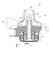
- FIG. FIG. 2 shows a state after the casing 120 is fitted into the base 110, and is a cross-sectional view when the blood pump 100 is cut along the xz plane shown in FIG. 1 when viewed along the y direction. is there.
- the blood pump 100 can be roughly grasped as a whole.
- the base 110, the casing 120 fitted in the base 110, and the pump chamber 150 enclosed by the base 110 and the casing 120 are accommodated.
- a liquid mechanism 130 and a driver 140 attached to the base 110 and applying energy to the liquid feeding mechanism 130 are provided.
- the blood pump 100 has a function of causing blood to flow into the pump chamber 150 and out of the pump chamber 150 by the liquid feeding mechanism 130 to feed the blood into the user's body (see FIGS. 1 and 2).
- the direction in which the casing 120 is slid and fitted to the base 110 is defined as the z direction
- the direction perpendicular to the z direction is defined as the x direction
- the directions perpendicular to the z direction and the x direction are defined as y.
- the direction from the center of the base 110 to the outside when the xy plane is viewed along the z direction is the r direction.
- the z direction is down, the -z direction is up, the -r direction is inside, the r direction is radial or outside, and in the case of a casing, the pump chamber side of the casing is inside, and the pump chamber is The opposite side may be referred to as the outside, and the direction parallel to the xy plane as the horizontal.
- FIG. 3 (a) and 3 (b) are enlarged views of an engagement portion surrounded by a dotted line in the cross-sectional view of FIG. 3A is a cross-sectional view showing the base 110 and the casing 120 before the casing 120 is fitted into the base 110, and FIG. 3B shows the state after the casing 120 is fitted into the base 110.
- FIG. 3C is an enlarged view of a portion surrounded by a dotted line in FIG. 3B.
- the base body 110 is provided on the ⁇ z direction side (upper side), and includes a substantially horizontal surface 111 including a blood contact surface 112 facing the pump chamber 150 and a first contact surface 113 contacting the casing 120.
- the blood contact surface 112 is a surface with which a user's blood contacts, and defines the pump chamber 150 together with the casing body 121.
- the first abutting surface is a surface that abuts on the second abutting surface 122 of the casing main body 121 and is a surface that receives the action of a pressing force (described later) from the second abutting surface 122.
- the blood contact surface 112 and the first contact surface 113 are formed continuously, and constitute a substantially horizontal surface 111 as a whole.
- the base 110 is provided on the r direction side, and includes a first engagement portion that includes a first taper portion 116 that inclines toward the ⁇ r direction (inner side) from the outer end portion 117 toward the z direction (downward). 115.
- the outer end portion 117 of the first tapered portion 116 protrudes most to the r direction side (outside), and the terminal end portion 118 of the first tapered portion 116 is the most ⁇ r direction side (inner side).
- the substrate 110 may be made of any material as long as it can constitute the blood pump 100 of the present invention, but may be made of the same material as the casing 120. However, even if a large force is applied to the base body 110 (particularly in the vicinity of the first engagement portion 115 and the first contact surface 113) from the second engagement portion 125 and the second contact surface 122 of the casing 120 described later. It is sufficiently hard and does not bend to such an extent that it does not deform, that is, it has sufficient rigidity to be regarded as a rigid body.
- the casing 120 is provided on the edge side of the casing main body 121 provided with the second contact surface 122 at a position corresponding to the first contact surface 113, and on the edge side of the casing 120.
- a second engagement portion 125 including a second taper portion 126 that inclines in the r direction (radial direction) from the inner end portion 127 toward the ⁇ z direction (upward) on the inner wall, and the casing body 121 and the second engagement.
- a casing intermediate portion 123 located in the middle of the portion 125.
- Reference numeral 124 denotes an inner wall of the intermediate portion.
- the casing main body 121 is provided with an inlet 152 through which blood flows in and an outlet 154 through which blood flows out, and the pump chamber 150 is defined by the inner wall of the casing main body 121 (FIG. 1). (See also FIG. 2).
- the inflow port 152 and the outflow port 154 are provided separately.
- a valve or the like outside the pump chamber 150 one inflow / outflow is made common. It may be configured as follows.
- the second abutting surface 122 of the casing main body 121 is pressed against the first abutting surface 113 of the base body 110 via the casing intermediate portion 123 by a force in the z direction (downward) generated in the second engaging portion 125. It is a surface that acts as pressure.
- the casing intermediate portion 123 has one end (upper side) coupled to the casing body 121 and the other end (lower side) coupled to the second engaging portion 125 in the cross-sectional view shown in FIG.
- the second tapered portion 126 constituting the second engaging portion 125 is a tapered shape that is inclined from the inner end portion 127 to the constricted portion 128 toward the r direction (radial direction) toward the ⁇ z direction (upward). It has become.
- the inner end portion 127 of the second tapered portion 126 protrudes most to the ⁇ r direction side (inner side).
- the liquid feeding mechanism 130 is installed inside the pump chamber 150 surrounded by the base 110 and the casing 120, and allows blood to flow into and out of the pump chamber 150 by a movable mechanism capable of flowing and feeding the liquid. Then, blood is fed into the user's body (see FIGS. 1 and 2).
- the driving body 140 is attached to the base 110 and gives energy to the liquid feeding mechanism 130 so that the liquid feeding mechanism 130 feeds the liquid.
- an impeller is employed as the liquid feeding mechanism 130, and a motor for driving the impeller is employed as the driving body 140.
- the impeller easily exhibits a liquid feeding function
- the motor has a relatively established control technology that exhibits linearity, responsiveness, etc., and it is relatively easy to perform control in accordance with a target. This is because by driving the impeller using such a motor, it is possible to efficiently exhibit a liquid feeding function as intended, and to provide a high-performance and high-accuracy blood pump.
- the motor is attached to the base 110 so that the stator part and the rotor part of the motor are stored in the ⁇ z direction side when viewed from the substantially horizontal plane 111 of the base body 110, and the z direction from the base 110 side is accommodated.
- the rotating shaft of the motor is protruded toward the side, and the impeller is coupled to the protruding rotating shaft (see FIGS. 1 and 2).
- the blood pump 100 engages with the first engagement portion 115 of the base 110 in a state where the second engagement portion 125 of the casing 120 is elastically deformed, and the second contact surface 122 of the casing 120. Is pressed so as to be in contact with the first contact surface 113 of the base 110 (see FIG. 3).
- “pressed” refers to a state in which the second contact surface 122 is not simply held against the first contact surface 113 but is always pressed.
- the first abutment surface 113 and the second abutment surface 122 are in contact with each other and are firmly pressed by the pressing force, so that the blood in the pump chamber 150 is transferred to the first abutment surface 113 and the second abutment surface 122.
- “degree of contact” is also referred to as “butting” or the like.
- “butting” For example, when a z-direction force is applied to the unit, the unit and the unit When the opposing opposing unit comes into contact with or comes into contact, and the force in the z direction is almost entirely applied to the opposing unit at the certain part (surface), the certain part (surface) is referred to as “ "Per degree”.
- the inner diameter of the inner end portion 127 of the second tapered portion 126 of the casing 120 before being fitted into the base body 110 is ⁇ A
- the outer end portion 117 of the first tapered portion 116 of the base body 110 is
- the outer diameter is ⁇ B
- a relationship of ⁇ A ⁇ B is satisfied, and the position of the inner end portion 127 of the second tapered portion 126 is in the z direction relative to the outer end portion 117 of the first tapered portion 116.
- the casing 120 is fitted into the base body 110 so as to be located at a position shifted to the side and in front of the end portion 118 opposite to the outer end portion 117 of the first tapered portion 116 (see FIG. 3 and FIG.
- the inner end portion 127 of the second taper portion 126 on the casing 120 side is located at a position on the z direction (lower) side over the outer end portion 117 of the first taper portion 116 on the base 110 side.
- the edge side of the casing 120 is maximized in the r direction (outer). It expands and deforms, thereby generating an elastic force.
- the elastic force is still maintained, and the elastic force is applied to the inner end portion 127 by the effect of the first tapered portion 116.
- the second engagement portion 125 of the casing 120 (and / or the entire casing) is converted to a force pushing the z direction (downward) via the first contact surface 122 on the casing 120 side to the base 110 side.
- a large pressing force can be applied to the first contact surface 113.
- the inner end portion of the casing 120 is difficult to move in the ⁇ z direction (upward). Thereby, the pressing force can be applied “always”.
- the casing lower end portion 129 on the edge side of the casing 120 is not in contact with the base 110 in the direction along the z direction (see FIG. 3).
- the lower end portion 129 of the casing is not in contact with the base body 110 and is in a free state. Even if the casing extends from the initial state due to a temperature change or the like, for example (or the base body contracts).
- the margin of extension is secured at the tip of the casing lower end portion 129, the casing lower end portion 129 hits against the base 110 and the extension is not restricted to reduce the pressing force.
- a large pressing force can be applied from the second contact surface 122 on the side to the first contact surface 113 on the base 110 side.
- the angle formed by the contour of the inclined surface of the first tapered portion 116 and the z direction is ⁇ 1
- ⁇ 1 ⁇ 2 it is preferable that ⁇ 1 ⁇ 2 (see FIGS. 3 and 4).
- the inner end portion 127 of the casing 120 is in contact with the first taper portion 116 of the base 110, and as described above, the inner end portion is affected by the effect of the first taper portion 116.
- a large pressing force can always be applied from the second contact surface 122 on the casing 120 side to the first contact surface 113 on the base 110 side via the portion 127.
- the first engagement portion 115 and the second engagement portion 125 are formed with high accuracy, and the casing lower end portion 129 is in the direction along the z direction.
- the pressing force based on the corresponding elastic force can be generated.
- the thickness of the casing main body 121 in the direction perpendicular to the outer tangent plane of the casing main body 121 is t1, when the blood pump 100 is cut along the xz plane.
- the thickness of the casing intermediate portion 123 in the direction perpendicular to the outer tangent plane of the casing intermediate portion 123 is t2, and the thickness of the second engaging portion 125 in the direction perpendicular to the outer tangential plane of the second engaging portion 125
- t3 is set to t3>t2> t3
- the opposite side to the inner end portion 127 is ⁇
- the thickness of the casing 120 is the smallest at the end portion (constriction 128) in the z direction (see FIGS.
- the casing intermediate portion 123 is preferably elastically deformed although it is smaller than the elastic deformation amount of the second engaging portion 125. According to these configurations, since the thickness gradually decreases from the casing main body 121 to the second engagement portion 125, the casing intermediate portion 123 also has a smaller deformation than the second engagement portion 125. Due to elastic deformation, a strong elastic force can be efficiently generated in the casing 120 as a whole like a fishing rod. In addition, in the middle from the casing main body 121 to the second engaging portion 125, a constricted portion 128 that is temporarily smaller in thickness than the others and becomes “necked” may be provided. By providing the constricted portion 128, the elastic force can be generated more efficiently.
- the first engagement portion 115 and the second engagement portion 125 when the first engagement portion 115 and the second engagement portion 125 are cut along the xy plane and viewed in plan along the z direction, the first engagement portion 115 and The second engaging portion 125 is circular.
- “circular” means that there are no corners, and examples thereof include an ellipse and a true circle.
- the second engagement portion 125 of the casing 120 may have a structure in which a “split” is inserted along the outer periphery.
- a continuous ring-like structure (substantially cylindrical) is preferable.
- this structure when the inner end portion 127 of the casing 120 gets over the outer end portion 117 of the base body 110, it is possible to generate a larger elastic force than that having a “split”.
- this structure even if the thickness of the second engagement portion 125, the casing intermediate portion 123, etc. of the casing 120 is reduced (thinned), sufficient elastic force can be secured, so that the size and weight can be reduced. Can contribute.
- the substantially horizontal surface 111 of the base 110 has a mirror finish.
- the value of Ra is preferably about 1.0 or less, and more preferably about 0.2 or less.
- the “substantially horizontal surface 111” refers to a surface that is horizontal when the blood pump 100 is placed in a normal state, but includes a surface that is slightly displaced. In addition, even if it is not horizontal (such as vertical) depending on the design and use state, it is defined here as “horizontal plane” or “substantially horizontal plane” for convenience. In addition, the blood contact surface 112 may not be a complete flat surface, for example, a slight curve may be drawn.
- the casing 120 may be made of any material as long as it can constitute the blood pump 100 of the first embodiment.
- pure titanium ATSM standard F67, grade 2 etc., JIS standard type 2 etc.
- titanium alloy titanium alloy
- stainless steel SUS type
- various other alloys are used. can do.
- a resin can be used as long as an elastic force is generated in the second engagement portion and a necessary pressing force can be generated.
- the casing 120 is made of a material mainly made of titanium. Titanium is (1) a material that has been confirmed as biocompatible and accepted as a medical embedded material, and (2) has sufficient tensile strength, yield strength, etc., and has high specific strength. Because it is strong, it is suitable for weight reduction, has an appropriate elastic modulus, and has physical properties suitable for constructing the casing of the present invention. This is because a blood pump for an artificial heart can be provided.
- the diameter of the inner end 127 of the second engagement portion 125 of the casing 120 is ⁇ A
- the diameter of the outer end 117 of the first engagement portion 115 of the base 110 is ⁇ B
- the thickness in the r direction near the constricted portion 128 of the second engagement portion 125 of the casing 120 is G
- the thickness in the r direction near the inner end portion 127 of the second engagement portion 125 of the casing 120 is t3, and the above.
- ⁇ 1 and ⁇ 2 When defined as ⁇ 1 and ⁇ 2 as described above, (i) the difference between ⁇ A and ⁇ B is approximately 0.1% to 1.0% of ⁇ B, and (ii) ⁇ A and ⁇ B G is in the range of 0.15 mm to 0.40 mm, and t3 is about twice as large as G, for example, in the range of 0.35 mm to 0.8 mm. It is preferable. Further, ⁇ 1 is preferably in the range of 2 ° to 10 °, and ⁇ 2 is preferably in the range of 4 ° to 20 °. It is preferable that ⁇ 2 is approximately twice as large as ⁇ 1 (see FIG. 4).
- the second contact surface 122 does not float from the first contact surface 113 depending on the internal pressure of the pump chamber 150 being (i) a pressure within the range of 0 mmHg to 200 mmHg ( No gaps).
- the second contact surface 122 does not float from the first contact surface 113 (no gap is generated) depending on the pressure in the pump chamber 150 within the range of 0 mmHg to 500 mmHg.
- the second contact surface 122 does not float from the first contact surface 113 (no gap is generated) depending on the pressure in the pump chamber 150 within the range of 0 mmHg to 1500 mmHg.
- FIG. 5 shows that the pressing force F2 from the second contact surface 122 against the first contact surface 113 is generated in the blood pump 100 according to the first embodiment. It is a figure shown in order to demonstrate a mode that it does.
- the first engagement portion 115 having the first taper portion 116 and the second engagement portion 125 having the second taper portion 126 are engaged (FIGS. 4 and 4). 5).
- casing 120 Prior to such a state, in the assembly process of blood pump 100, casing 120 is fitted so as to be press-fitted into base 110 from an extremely tight state.
- the edge side of the casing 120 is expanded to the r direction side (outside) as a whole and elastically deformed from the state before fitting, and thereby the -r direction (inside).
- An elastic force F ⁇ b> 1 force for tightening the base body 110 that attempts to return to is generated.
- an extremely large elastic force F ⁇ b> 1 acts on the first tapered portion 116 around the vicinity of the inner end portion 127 of the second engagement portion 125.
- the base 110 side including the first tapered portion 116 can be regarded as a rigid body as described above, when the elastic force F1 is applied, conversely, in the direction perpendicular to the contact surface of the first tapered portion 116, A normal force is generated against the two engaging portions 125.
- a force F2 of a component in the z direction (downward) of the vertical drag is also generated.
- This F2 is a force that pushes down the entire casing 120 in the z direction (downward), and in conjunction with this, the F2 is large from the second contact surface 122 on the casing 120 side to the first contact surface 113 on the base 110 side.
- the pressing force F2 is energized. Further, since the position of the inner end portion 127 is located at a position shifted to the z direction side from the outer end portion 117, the inner end portion of the casing 120 is difficult to move in the ⁇ z direction (upward). As a result, the above-mentioned pressing force can be applied “always” (see FIG. 3 in addition to FIG. 5).
- the first contact surface 113 of the base 110 functions as a contact with the second contact surface 122 of the casing 120, and in other locations, there are locations that receive the z-direction (downward) force from the casing. It is desirable that there is no.
- the part not related to the function can be made as small as possible, and the blood pump can be configured with a margin MG1 much smaller than the screw fastening allowance MG2 in the conventional blood pump. It is possible to provide a useful blood pump having a smaller diameter, volume, etc. than that of the pump. (C) To provide a useful blood pump capable of satisfying both (a) and (b) described above. Kill naturally by the effect (d) blood does not leak to the outside, and can be such as an external fluid to provide a blood pump which does not get inside.
- the blood pump 100 may of course be installed outside the user's body, but of course, if it is implanted in the body and used as an auxiliary artificial heart, it will further benefit from a reduction in size and weight. be able to.
- a blood pump When a blood pump is implanted in the body, it will be implanted in the chest of a user (patient) of a limited thickness, so it has a smaller diameter, volume, etc. than before while satisfying the basic required specifications. This is because if the blood pump of the present invention is used, the number of persons to be applied can be expanded, and requests from medical sites can be more appropriately met.
- the blood pump is expressed as “implanted” in the body, but may be expressed as “implant”.
- FIG. 6 is a diagram schematically illustrating the auxiliary artificial heart system 300 when the blood pump 100 according to the first embodiment is implanted in the body.
- the auxiliary artificial heart system 300 connects the blood pump 100 embedded in the user's body, the blood pump 100, and the left ventricle (not shown) of the user's own heart 510.
- the cable 220 is connected to the pump 100.
- the blood pump 100 according to the first embodiment having a smaller diameter, volume and the like than the conventional blood pump while satisfying necessary specifications, for example, a small human body such as a child ( It can be implanted in the body of a patient), and can be expected to greatly expand the number of people who can apply the blood pump.
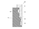
- FIG. 7 is a view for explaining a main part of the blood pump 100a according to the second embodiment, and is an enlarged view of an engagement portion surrounded by a dotted line in the cross-sectional view of FIG.
- part which becomes the structure similar to the structure of Embodiment 1 has attached
- the blood pump 100a according to the second embodiment basically has the same configuration as that of the blood pump 100 according to the first embodiment, but is different from the blood pump 100 according to the first embodiment in that a configuration related to the packing 160 is added.
- the base 110 is a packing groove for dropping the packing 160 to a position on the ⁇ z direction side (upper side) from the first engagement portion 115.
- the casing 120 has an intermediate inner wall 124 at the position of the casing intermediate portion 123, and the packing 160 is disposed so as to be sandwiched between the packing groove 119 and the intermediate inner wall 124.
- the blood pump 100a according to the second embodiment is different from the blood pump 100 according to the first embodiment in that a configuration related to the packing 160 is added.
- the outer side of the packing is further sealed. Since 160 is arranged, it is possible to block the leakage of blood to the outside of the blood pump, and to block body fluid and the like from entering the inside of the blood pump from the outside of the blood pump. it can. Since the packing 160 is crushed in the ⁇ r direction or the r direction by the elastic force of the casing intermediate portion 123, the diameter of the blood pump is not increased.
- the packing groove 119 of the base 110 overlaps the substantially horizontal surface 111 of the base 110, and the casing 120 It is preferable that the second contact surface 122 overlaps at least a part of the packing 160.
- the packing 160 is incorporated into the blood pump 100a such that at least a part of the thickness in the r direction of the packing 160 is absorbed by the regions of the substantially horizontal surface 111 and the second contact surface 122. Therefore, the packing can be added without particularly increasing the diameter of the blood pump, and a blood pump having a small diameter, volume, etc. can be provided.
- the blood pump 100a which concerns on Embodiment 2 since it has the structure similar to the blood pump 100 which concerns on Embodiment 1 except the structure regarding the packing 160, it is applicable among the effects which the blood pump 100 which concerns on Embodiment 1 has. It has the effect to do as it is.
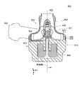
- FIG. 8 is a view for explaining the blood pump 100b according to the third embodiment, and is a perspective view showing a state before the casing 120 and another casing 170 are fitted into the base 110, respectively.
- the blood pump 100b according to the third embodiment basically has the same configuration as that of the blood pump 100 according to the first embodiment and the blood pump 100a according to the second embodiment. This is different from blood pumps 100 and 100a according to the first and second embodiments in that another casing 170 is fitted on the side). That is, as shown in FIG. 8, in the blood pump 100b according to the third embodiment, the base 110 has a storage chamber for storing a driving body (rotor portion of the motor) opened on the z direction side (bottom surface side) and the like. (Not shown in the figure), the driving body (the rotor part of the motor) is stored in the storage chamber, and another casing 170 is fitted on the z direction side (bottom side) of the base 110. As a result, the storage chamber is casing.
- the fitting structure between another casing 170 and the base 110 is the same as the fitting structure between the casing 120 and the base 110 in the first embodiment. That is, another first engagement portion similar to the first engagement portion 115 is provided on the z direction side (bottom surface side) of the base body 110, and the second engagement portion 125 is provided on the edge side of another casing 170. Another similar second engaging portion is provided. In the same manner as in the first embodiment, another first engaging portion and another second engaging portion are fitted with the same structure.
- the blood pump 100b according to the third embodiment is different from the blood pump 100 according to the first embodiment and the second embodiment in that another casing 170 is fitted to the base 110 on the z-direction side (bottom surface side).
- another casing 170 is fitted from the z-direction side (bottom surface side) with the same structure as the first embodiment. Even if it is necessary to provide a storage chamber, the storage chamber can be closed with another casing 170 without securing a large margin (such as a fastening allowance), so a blood pump having a small diameter, volume, etc. is provided. can do.
- the blood pump 100 according to the first embodiment and the second embodiment except that another casing 170 is fitted to the base 110 on the z-direction side (bottom surface side). Since the blood pump 100a according to the first embodiment has the same configuration, the blood pump 100 and the blood pump 100a according to the first and second embodiments have the corresponding effects as they are.
- Example A blood pump according to Embodiments 2 and 3 was manufactured as a blood pump according to Example. That is, as a blood pump according to the example, in addition to the fitting structure of the base 110 and the casing 120 according to the first embodiment, a packing 160 and another casing 170 (back cover) are also employed.
- the liquid feeding mechanism 130 employs an impeller, the driver 140 employs a motor, and pure titanium (ATSM standard F67, grade 2) is employed as the material of the base 110 and the casing 120.
- SAM standard F67, grade 2 pure titanium
- Comparative Example 1 a blood pump based on a watch cover mounting structure (background art) that is widely used in general was manufactured as a prototype.
- Comparative Example 2 a conventional blood pump 800 (see FIGS.
- Comparative Example 1 the structure for bonding the base body and the casing is a structure using a dowel portion in Comparative Example 1, and a structure using a screw is used in Comparative Example 2.
- the structure, dimensions, etc. of the parts related to other basic functions were basically the same as those in the example.
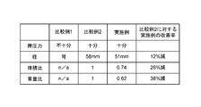
- FIG. 9 is a diagram for explaining the evaluation results of the blood pump according to the example.
- the blood pump according to the example can reduce the diameter of the whole blood pump by 12% and the volume of the whole blood pump by 26% compared to the blood pump of Comparative Example 2. It was confirmed that the weight could be reduced by 38%.
- the blood pump of the present invention can always apply a large pressing force from the casing-side contact surface to the base-side contact surface, and even when the pressure in the pump chamber increases, the pump chamber is defined. Confirming that the diameter, volume, etc. are smaller than those of conventional blood pumps, while satisfying the required specifications that there is no gap between the contact surface on the casing side and the contact surface on the substrate side did.
- the end on the most z-direction side of the second engagement portion 125 was also the end on the most z-direction side (casing lower end portion 129) in the casing 120. It is not limited.
- a cover portion 129 ′ that does not contribute to engagement is provided further on the z direction side than the portion of the second engagement portion 125, and the z direction side (lower end) of the cover portion 129 ′ is provided.
- the end of the cover portion 129 ′ on the z direction side (casing lower end portion 129) is not in contact with the base 110 in the direction along the z direction.
- the packing 160 is disposed at a position corresponding to the casing intermediate portion 123, but the present invention is not limited to this. For example, you may arrange
- the packing groove 119 and the intermediate inner wall 124 of the casing 120 facing the packing groove 119 are provided along the z direction and are configured to be parallel to each other.
- the present invention is not limited to this (see FIG. 7).
- the intermediate part inner wall 124 may be tapered so as to incline toward the ⁇ r direction (inward) as it goes in the z direction (downward) (not shown).
- Such elastic force pushes the intermediate portion inner wall 124 ′ and the packing groove 119, and can finally be energized as part of the force that lowers the casing 120 in the z direction.
- the design on the packing groove 119 side may be changed to provide a taper that exhibits the same effect.
- the first contact surface 113 and the second contact surface 122 are assumed to be parallel to each other.
- the present invention is not limited to this. Absent.
- the second contact surface 122 may be configured not to be parallel (that is, horizontal) to the zy plane but to be inclined in the z direction (down) as it goes in the ⁇ r direction (inner side).
- the second abutment surface 122 that contacts the first abutment surface 113 is smaller in area than the above-described embodiments, but gives the above-described pressing force F2 in a small area. High pressure can be applied to the contact surface 113.
- the casing intermediate portion 123 is disposed between the casing main body 121 and the second engaging portion 125, but the present invention is not limited to this.
- the casing intermediate portion 123 may be omitted.
- an impeller is employed as the liquid feeding mechanism 130, but the present invention is not limited to this.
- a liquid feeding mechanism such as a bladeless type, a cylinder type, a pulsation type, a turbo type, a volume type, or a flagellar movement type may be employed.
- the blood pump according to each of the above embodiments has been described assuming that it is used by being implanted in the body, the present invention is not limited to this.
- the blood pump of the present invention is useful even if it is installed outside the user's body. This is because there is a strong demand for a small and light blood pump because the blood pump needs to be carried along with the movement of the user.
Landscapes
- Health & Medical Sciences (AREA)
- Heart & Thoracic Surgery (AREA)
- Engineering & Computer Science (AREA)
- Cardiology (AREA)
- Life Sciences & Earth Sciences (AREA)
- Anesthesiology (AREA)
- Biomedical Technology (AREA)
- Hematology (AREA)
- Mechanical Engineering (AREA)
- Animal Behavior & Ethology (AREA)
- General Health & Medical Sciences (AREA)
- Public Health (AREA)
- Veterinary Medicine (AREA)
- Human Computer Interaction (AREA)
- Vascular Medicine (AREA)
- External Artificial Organs (AREA)
- Structures Of Non-Positive Displacement Pumps (AREA)
Abstract
Priority Applications (5)
| Application Number | Priority Date | Filing Date | Title |
|---|---|---|---|
| JP2018512696A JP6661861B2 (ja) | 2016-04-20 | 2016-04-20 | 血液ポンプ |
| US16/094,876 US20190125947A1 (en) | 2016-04-20 | 2016-04-20 | Blood pump |
| EP16899397.0A EP3446728A4 (fr) | 2016-04-20 | 2016-04-20 | Pompe d'assistance circulatoire |
| CN201680084718.0A CN109069715B (zh) | 2016-04-20 | 2016-04-20 | 血液泵 |
| PCT/JP2016/062456 WO2017183124A1 (fr) | 2016-04-20 | 2016-04-20 | Pompe d'assistance circulatoire |
Applications Claiming Priority (1)
| Application Number | Priority Date | Filing Date | Title |
|---|---|---|---|
| PCT/JP2016/062456 WO2017183124A1 (fr) | 2016-04-20 | 2016-04-20 | Pompe d'assistance circulatoire |
Publications (1)
| Publication Number | Publication Date |
|---|---|
| WO2017183124A1 true WO2017183124A1 (fr) | 2017-10-26 |
Family
ID=60115744
Family Applications (1)
| Application Number | Title | Priority Date | Filing Date |
|---|---|---|---|
| PCT/JP2016/062456 Ceased WO2017183124A1 (fr) | 2016-04-20 | 2016-04-20 | Pompe d'assistance circulatoire |
Country Status (5)
| Country | Link |
|---|---|
| US (1) | US20190125947A1 (fr) |
| EP (1) | EP3446728A4 (fr) |
| JP (1) | JP6661861B2 (fr) |
| CN (1) | CN109069715B (fr) |
| WO (1) | WO2017183124A1 (fr) |
Cited By (13)
| Publication number | Priority date | Publication date | Assignee | Title |
|---|---|---|---|---|
| US10722631B2 (en) | 2018-02-01 | 2020-07-28 | Shifamed Holdings, Llc | Intravascular blood pumps and methods of use and manufacture |
| US11185677B2 (en) | 2017-06-07 | 2021-11-30 | Shifamed Holdings, Llc | Intravascular fluid movement devices, systems, and methods of use |
| US11511103B2 (en) | 2017-11-13 | 2022-11-29 | Shifamed Holdings, Llc | Intravascular fluid movement devices, systems, and methods of use |
| US11654275B2 (en) | 2019-07-22 | 2023-05-23 | Shifamed Holdings, Llc | Intravascular blood pumps with struts and methods of use and manufacture |
| US11724089B2 (en) | 2019-09-25 | 2023-08-15 | Shifamed Holdings, Llc | Intravascular blood pump systems and methods of use and control thereof |
| US11964145B2 (en) | 2019-07-12 | 2024-04-23 | Shifamed Holdings, Llc | Intravascular blood pumps and methods of manufacture and use |
| US12102815B2 (en) | 2019-09-25 | 2024-10-01 | Shifamed Holdings, Llc | Catheter blood pumps and collapsible pump housings |
| US12121713B2 (en) | 2019-09-25 | 2024-10-22 | Shifamed Holdings, Llc | Catheter blood pumps and collapsible blood conduits |
| US12161857B2 (en) | 2018-07-31 | 2024-12-10 | Shifamed Holdings, Llc | Intravascular blood pumps and methods of use |
| US12220570B2 (en) | 2018-10-05 | 2025-02-11 | Shifamed Holdings, Llc | Intravascular blood pumps and methods of use |
| US12409310B2 (en) | 2019-12-11 | 2025-09-09 | Shifamed Holdings, Llc | Descending aorta and vena cava blood pumps |
| US12465748B2 (en) | 2019-08-07 | 2025-11-11 | Supira Medical, Inc. | Catheter blood pumps and collapsible pump housings |
| US12599758B2 (en) | 2019-12-19 | 2026-04-14 | Shifamed Holdings, Llc | Intravascular blood pumps, motors, and fluid control |
Families Citing this family (1)
| Publication number | Priority date | Publication date | Assignee | Title |
|---|---|---|---|---|
| JP7262099B2 (ja) * | 2018-12-26 | 2023-04-21 | 株式会社サンメディカル技術研究所 | 血液ポンプコントローラ及び補助人工心臓システム |
Citations (4)
| Publication number | Priority date | Publication date | Assignee | Title |
|---|---|---|---|---|
| JPH0775667A (ja) * | 1993-04-28 | 1995-03-20 | Kyocera Corp | 血液ポンプ |
| JPH11244376A (ja) * | 1998-02-27 | 1999-09-14 | Kyocera Corp | 血液ポンプ |
| JP2003135592A (ja) * | 2001-11-02 | 2003-05-13 | Terumo Corp | 医療器具およびその製造方法ならびに遠心式液体ポンプ |
| JP2012193658A (ja) * | 2011-03-16 | 2012-10-11 | Jms Co Ltd | ターボ式血液ポンプ及びその製造方法 |
Family Cites Families (12)
| Publication number | Priority date | Publication date | Assignee | Title |
|---|---|---|---|---|
| JPH0411715Y2 (fr) * | 1985-08-30 | 1992-03-24 | ||
| US5575630A (en) * | 1995-08-08 | 1996-11-19 | Kyocera Corporation | Blood pump having magnetic attraction |
| WO2001092969A1 (fr) * | 2000-05-31 | 2001-12-06 | Citizen Watch Co., Ltd. | Appareil horaire thermo-generateur et son couvercle dorsal |
| EP1420307A1 (fr) * | 2002-11-18 | 2004-05-19 | Eterna SA | Boíte de montre |
| US7846123B2 (en) * | 2007-04-24 | 2010-12-07 | Emory University | Conduit device and system for implanting a conduit device in a tissue wall |
| JP2010127683A (ja) * | 2008-11-26 | 2010-06-10 | Seiko Instruments Inc | 携帯時計 |
| WO2011024470A2 (fr) * | 2009-08-28 | 2011-03-03 | 国立大学法人東京工業大学 | Pompe centrifuge à suspension magnétique jetable |
| WO2012158968A2 (fr) * | 2011-05-18 | 2012-11-22 | Thoratec Corporation | Protecteur d'aiguille, ensemble et méthode d'implantation d'un système d'assistance cardiaque |
| WO2013056131A1 (fr) * | 2011-10-13 | 2013-04-18 | Reichenbach Steven H | Pompe et procédé de pompage de sang à débit mélangé |
| EP4252823A3 (fr) * | 2012-08-15 | 2023-11-15 | Artio Medical, Inc. | Systèmes et procédés de pompe d'assistance circulatoire |
| CN202990591U (zh) * | 2012-12-10 | 2013-06-12 | 苏州旲烔机电科技有限公司 | 一种机械壳体 |
| JP5967156B2 (ja) * | 2014-08-29 | 2016-08-10 | カシオ計算機株式会社 | 時計 |
-
2016
- 2016-04-20 US US16/094,876 patent/US20190125947A1/en not_active Abandoned
- 2016-04-20 CN CN201680084718.0A patent/CN109069715B/zh active Active
- 2016-04-20 JP JP2018512696A patent/JP6661861B2/ja active Active
- 2016-04-20 EP EP16899397.0A patent/EP3446728A4/fr not_active Withdrawn
- 2016-04-20 WO PCT/JP2016/062456 patent/WO2017183124A1/fr not_active Ceased
Patent Citations (4)
| Publication number | Priority date | Publication date | Assignee | Title |
|---|---|---|---|---|
| JPH0775667A (ja) * | 1993-04-28 | 1995-03-20 | Kyocera Corp | 血液ポンプ |
| JPH11244376A (ja) * | 1998-02-27 | 1999-09-14 | Kyocera Corp | 血液ポンプ |
| JP2003135592A (ja) * | 2001-11-02 | 2003-05-13 | Terumo Corp | 医療器具およびその製造方法ならびに遠心式液体ポンプ |
| JP2012193658A (ja) * | 2011-03-16 | 2012-10-11 | Jms Co Ltd | ターボ式血液ポンプ及びその製造方法 |
Non-Patent Citations (1)
| Title |
|---|
| See also references of EP3446728A4 * |
Cited By (16)
| Publication number | Priority date | Publication date | Assignee | Title |
|---|---|---|---|---|
| US11185677B2 (en) | 2017-06-07 | 2021-11-30 | Shifamed Holdings, Llc | Intravascular fluid movement devices, systems, and methods of use |
| US11717670B2 (en) | 2017-06-07 | 2023-08-08 | Shifamed Holdings, LLP | Intravascular fluid movement devices, systems, and methods of use |
| US11511103B2 (en) | 2017-11-13 | 2022-11-29 | Shifamed Holdings, Llc | Intravascular fluid movement devices, systems, and methods of use |
| US12076545B2 (en) | 2018-02-01 | 2024-09-03 | Shifamed Holdings, Llc | Intravascular blood pumps and methods of use and manufacture |
| US11229784B2 (en) | 2018-02-01 | 2022-01-25 | Shifamed Holdings, Llc | Intravascular blood pumps and methods of use and manufacture |
| US10722631B2 (en) | 2018-02-01 | 2020-07-28 | Shifamed Holdings, Llc | Intravascular blood pumps and methods of use and manufacture |
| US12161857B2 (en) | 2018-07-31 | 2024-12-10 | Shifamed Holdings, Llc | Intravascular blood pumps and methods of use |
| US12220570B2 (en) | 2018-10-05 | 2025-02-11 | Shifamed Holdings, Llc | Intravascular blood pumps and methods of use |
| US11964145B2 (en) | 2019-07-12 | 2024-04-23 | Shifamed Holdings, Llc | Intravascular blood pumps and methods of manufacture and use |
| US11654275B2 (en) | 2019-07-22 | 2023-05-23 | Shifamed Holdings, Llc | Intravascular blood pumps with struts and methods of use and manufacture |
| US12465748B2 (en) | 2019-08-07 | 2025-11-11 | Supira Medical, Inc. | Catheter blood pumps and collapsible pump housings |
| US12102815B2 (en) | 2019-09-25 | 2024-10-01 | Shifamed Holdings, Llc | Catheter blood pumps and collapsible pump housings |
| US12121713B2 (en) | 2019-09-25 | 2024-10-22 | Shifamed Holdings, Llc | Catheter blood pumps and collapsible blood conduits |
| US11724089B2 (en) | 2019-09-25 | 2023-08-15 | Shifamed Holdings, Llc | Intravascular blood pump systems and methods of use and control thereof |
| US12409310B2 (en) | 2019-12-11 | 2025-09-09 | Shifamed Holdings, Llc | Descending aorta and vena cava blood pumps |
| US12599758B2 (en) | 2019-12-19 | 2026-04-14 | Shifamed Holdings, Llc | Intravascular blood pumps, motors, and fluid control |
Also Published As
| Publication number | Publication date |
|---|---|
| EP3446728A1 (fr) | 2019-02-27 |
| US20190125947A1 (en) | 2019-05-02 |
| JPWO2017183124A1 (ja) | 2019-02-28 |
| JP6661861B2 (ja) | 2020-03-11 |
| CN109069715B (zh) | 2021-02-02 |
| EP3446728A4 (fr) | 2019-12-18 |
| CN109069715A (zh) | 2018-12-21 |
Similar Documents
| Publication | Publication Date | Title |
|---|---|---|
| WO2017183124A1 (fr) | Pompe d'assistance circulatoire | |
| US11957872B2 (en) | Deformable valve mechanism for controlling fluid delivery | |
| US20150285258A1 (en) | Centrifugal Pump | |
| JP2019069013A (ja) | 血液ポンプ及び血液ポンプの製造方法 | |
| US7654283B2 (en) | Check valve and pump including check valve | |
| JP3718724B2 (ja) | マイクロポンプ | |
| US12013044B2 (en) | Valve and application apparatus | |
| US8545484B2 (en) | Accumulator for implantable infusion device | |
| JP2006204343A (ja) | 補助人工心臓 | |
| JP2005188355A (ja) | ダイアフラムポンプ | |
| JP2006000631A (ja) | 体内埋込式補助人工心臓 | |
| JP2008101566A (ja) | ダイヤフラムポンプ及び薄型流路構造 | |
| CN107007894A (zh) | 一种超声直线电机驱动的可植入式搏动血泵 | |
| WO2020201270A1 (fr) | Dispositif médical ambulatoire avec vibreur | |
| JP2024541250A (ja) | 気道を開くためのデバイス及び方法 | |
| JP2008106865A (ja) | 逆止弁及びその製造方法 | |
| CN221888537U (zh) | 眼科手术对接装置 | |
| JP2017153520A (ja) | 手術用ハンドピース、液体噴射装置、吸引装置 | |
| JPS62159656A (ja) | カニユ−レ | |
| US12127992B1 (en) | Massager with non-contact driving apparatus | |
| CN114555144B (zh) | 吸奶器 | |
| JP3007424B2 (ja) | 人工弁シール装置の製造方法 | |
| JP2023149472A (ja) | 血液ポンプ装置 | |
| CN110541807B (zh) | 一种单阀双腔压电泵及其工作方法 | |
| WO2017150147A1 (fr) | Instrument à main chirurgical, dispositif d'éjection de liquide et dispositif d'aspiration |
Legal Events
| Date | Code | Title | Description |
|---|---|---|---|
| ENP | Entry into the national phase |
Ref document number: 2018512696 Country of ref document: JP Kind code of ref document: A |
|
| NENP | Non-entry into the national phase |
Ref country code: DE |
|
| WWE | Wipo information: entry into national phase |
Ref document number: 2016899397 Country of ref document: EP |
|
| ENP | Entry into the national phase |
Ref document number: 2016899397 Country of ref document: EP Effective date: 20181120 |
|
| 121 | Ep: the epo has been informed by wipo that ep was designated in this application |
Ref document number: 16899397 Country of ref document: EP Kind code of ref document: A1 |