WO2017183145A1 - Capteur laser et procédé de fabrication d'un constituant extérieur - Google Patents
Capteur laser et procédé de fabrication d'un constituant extérieur Download PDFInfo
- Publication number
- WO2017183145A1 WO2017183145A1 PCT/JP2016/062574 JP2016062574W WO2017183145A1 WO 2017183145 A1 WO2017183145 A1 WO 2017183145A1 JP 2016062574 W JP2016062574 W JP 2016062574W WO 2017183145 A1 WO2017183145 A1 WO 2017183145A1
- Authority
- WO
- WIPO (PCT)
- Prior art keywords
- optical window
- light
- transfer
- exterior
- laser
- Prior art date
- Legal status (The legal status is an assumption and is not a legal conclusion. Google has not performed a legal analysis and makes no representation as to the accuracy of the status listed.)
- Ceased
Links
Images




Classifications
-
- G—PHYSICS
- G01—MEASURING; TESTING
- G01B—MEASURING LENGTH, THICKNESS OR SIMILAR LINEAR DIMENSIONS; MEASURING ANGLES; MEASURING AREAS; MEASURING IRREGULARITIES OF SURFACES OR CONTOURS
- G01B11/00—Measuring arrangements characterised by the use of optical techniques
- G01B11/02—Measuring arrangements characterised by the use of optical techniques for measuring length, width or thickness
- G01B11/026—Measuring arrangements characterised by the use of optical techniques for measuring length, width or thickness by measuring distance between sensor and object
-
- G—PHYSICS
- G01—MEASURING; TESTING
- G01B—MEASURING LENGTH, THICKNESS OR SIMILAR LINEAR DIMENSIONS; MEASURING ANGLES; MEASURING AREAS; MEASURING IRREGULARITIES OF SURFACES OR CONTOURS
- G01B11/00—Measuring arrangements characterised by the use of optical techniques
- G01B11/26—Measuring arrangements characterised by the use of optical techniques for measuring angles or tapers; for testing the alignment of axes
-
- G—PHYSICS
- G01—MEASURING; TESTING
- G01S—RADIO DIRECTION-FINDING; RADIO NAVIGATION; DETERMINING DISTANCE OR VELOCITY BY USE OF RADIO WAVES; LOCATING OR PRESENCE-DETECTING BY USE OF THE REFLECTION OR RERADIATION OF RADIO WAVES; ANALOGOUS ARRANGEMENTS USING OTHER WAVES
- G01S17/00—Systems using the reflection or reradiation of electromagnetic waves other than radio waves, e.g. lidar systems
- G01S17/02—Systems using the reflection of electromagnetic waves other than radio waves
- G01S17/06—Systems determining position data of a target
- G01S17/42—Simultaneous measurement of distance and other co-ordinates
-
- G—PHYSICS
- G01—MEASURING; TESTING
- G01S—RADIO DIRECTION-FINDING; RADIO NAVIGATION; DETERMINING DISTANCE OR VELOCITY BY USE OF RADIO WAVES; LOCATING OR PRESENCE-DETECTING BY USE OF THE REFLECTION OR RERADIATION OF RADIO WAVES; ANALOGOUS ARRANGEMENTS USING OTHER WAVES
- G01S7/00—Details of systems according to groups G01S13/00, G01S15/00, G01S17/00
- G01S7/48—Details of systems according to groups G01S13/00, G01S15/00, G01S17/00 of systems according to group G01S17/00
- G01S7/481—Constructional features, e.g. arrangements of optical elements
- G01S7/4811—Constructional features, e.g. arrangements of optical elements common to transmitter and receiver
-
- G—PHYSICS
- G01—MEASURING; TESTING
- G01S—RADIO DIRECTION-FINDING; RADIO NAVIGATION; DETERMINING DISTANCE OR VELOCITY BY USE OF RADIO WAVES; LOCATING OR PRESENCE-DETECTING BY USE OF THE REFLECTION OR RERADIATION OF RADIO WAVES; ANALOGOUS ARRANGEMENTS USING OTHER WAVES
- G01S7/00—Details of systems according to groups G01S13/00, G01S15/00, G01S17/00
- G01S7/48—Details of systems according to groups G01S13/00, G01S15/00, G01S17/00 of systems according to group G01S17/00
- G01S7/481—Constructional features, e.g. arrangements of optical elements
- G01S7/4811—Constructional features, e.g. arrangements of optical elements common to transmitter and receiver
- G01S7/4813—Housing arrangements
-
- G—PHYSICS
- G01—MEASURING; TESTING
- G01S—RADIO DIRECTION-FINDING; RADIO NAVIGATION; DETERMINING DISTANCE OR VELOCITY BY USE OF RADIO WAVES; LOCATING OR PRESENCE-DETECTING BY USE OF THE REFLECTION OR RERADIATION OF RADIO WAVES; ANALOGOUS ARRANGEMENTS USING OTHER WAVES
- G01S7/00—Details of systems according to groups G01S13/00, G01S15/00, G01S17/00
- G01S7/48—Details of systems according to groups G01S13/00, G01S15/00, G01S17/00 of systems according to group G01S17/00
- G01S7/481—Constructional features, e.g. arrangements of optical elements
- G01S7/4817—Constructional features, e.g. arrangements of optical elements relating to scanning
Definitions
- the present invention relates to a laser sensor that detects an object from laser light reflected by the object and a method for manufacturing an exterior part for the laser sensor.
- a sensor that identifies the size, speed, distance from a sensor, and the like of a target object by using reflected light returned from a detection target by irradiating a laser beam is known (for example, Patent Document 1). And 2).
- the sensor is covered with a protective exterior component.
- the exterior component emits a projection beam from an internal laser light source toward an external object, and reflects light from the detection target inside.
- transmits the light of the wavelength range of the irradiated laser is provided.
- the optical window main body and the parts other than the optical window are manufactured separately, and these are joined to form an exterior part of the sensor.
- the accuracy of the optical window when the optical window has a curved surface, there is a problem that manufacturing errors such as a shape error during bending and a thickness error during injection molding are likely to occur. Further, when the optical window is attached to a component with an adhesive or the like, there is a problem that the surface shape of the optical window is easily distorted by stress. As described above, if the accuracy of the optical window is poor, the laser beam cannot be projected and received at the target position, and the amount of light is reduced.
- the detection accuracy may be significantly deteriorated at a long distance side.
- dustproof and waterproof properties when the optical window is made of resin and the parts to which it is attached are made of metal, the joints easily peel off due to the difference in linear expansion when the environment changes, such as temperature, and dust and moisture are contained inside. There is a problem that it enters the state.
- weight reduction and downsizing there are limitations related to matters such as securing parts and securing the joining range in terms of securing strength, etc., making it difficult to apply to small mobile objects such as drones. There's a problem.
- the present invention has been made in view of the above problems of the background art, and an object thereof is to provide a laser sensor having a high-precision optical window and having good dustproof and waterproof properties.
- a laser sensor includes a light projecting unit, a light receiving unit that detects reflected light from a detection target from which laser light from the light projecting unit is emitted, a light projecting unit, and a light receiving unit.
- the exterior part covers an optical window that transmits laser light and reflected light, and a holding part that surrounds the outer periphery of the optical window, and the optical window and the holding part are: It is a resin-made integral molded product that is transparent in the wavelength range of the laser beam, the optical window has a pair of curved optical surfaces facing each other, and the holding portion is positioned relatively far from the optical window. It has a gate part and has a light shielding part that shields laser light and disturbance light at least adjacent to the optical window.
- disturbance light means light unnecessary for detection by a light receiving unit such as sunlight or light from a fluorescent lamp.
- the optical window and the holding part of the exterior part are an integrally molded product of resin, it is not necessary to join the optical window to the holding part separately, so that it has excellent dustproof and waterproof properties. Also, by integrating the optical window and the holding part, the exterior parts of the laser sensor have a relatively high rigidity, and the variation in shape due to shrinkage and deformation during molding is reduced, so that a highly accurate optical window can be obtained. It will have. Further, by integrating the optical window and the holding portion, structural or shape restrictions are reduced as compared with the case where the optical window is separately joined, and the laser sensor can be reduced in weight and size.
- the exterior component manufacturing method is a method for manufacturing an exterior component for a laser sensor, and includes a window transfer portion that forms an optical window that transmits at least laser light and reflected light of the laser sensor among the exterior components. And a molding step of integrally molding an exterior part from a resin having transparency in the wavelength region of the laser beam using a mold including a holding transfer portion that forms a holding portion surrounding the outer periphery of the optical window, and holding A light-shielding process for forming a light-shielding part that shields laser light and disturbance light on the part, the window transfer part has a curved transfer surface, and the holding transfer part is relatively separated from the window transfer part Has a gate in position.
- the optical window and the holding part of the exterior part are integrally formed using a resin, there is no need to separately join the optical window to the holding part. Obtainable.
- the exterior part has a relatively high rigidity, and there is less variation in shape due to shrinkage and deformation during molding, and it has a highly accurate optical window. Become.
- structural or shape restrictions are reduced as compared with the case where the optical window is separately joined, and it is possible to cope with the reduction in weight and size of the exterior part.
- by providing the gate at a position relatively distant from the window transfer portion it is possible to suppress the deformation of the surface shape of the optical window due to distortion of the gate portion during molding.
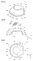
- FIG. 2A to 2C are a perspective view, a cross-sectional view, and a plan view for explaining a main exterior part of an exterior part of the laser sensor shown in FIG. 3A to 3C are views for explaining a method of manufacturing the main exterior part of the exterior part.
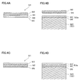
- 4A to 4D are diagrams for explaining the hard coat process.
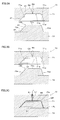
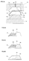
- 5A to 5D are views for explaining a method of manufacturing a main exterior part of an exterior part. It is a figure explaining the metal mold
- 7A to 7C are views for explaining a method of manufacturing the main exterior part of the exterior component according to the third embodiment.
- 8A to 8D are views for explaining a method of manufacturing the main exterior part of the exterior component according to the third embodiment. It is the schematic explaining the structure of the laser sensor which concerns on 4th Embodiment.
- 10A and 10B are diagrams for explaining a modification of the hard coat process and the antireflection process. It is a figure explaining the modification of the main exterior part shown to FIG. 2C etc. It is a figure explaining the modification of the manufacturing method of the main exterior part shown to FIG. 3B.
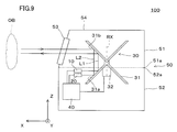
- FIG. 1 shows a schematic structure of a laser sensor 100 according to the first embodiment of the present invention.
- the laser sensor 100 is an object detection device for indoor / outdoor monitoring or in-vehicle use, for example, and detects the presence of a detection target and the distance to the detection target.
- the laser sensor 100 includes a light projecting unit 10, a light receiving unit 20, a rotary reflection unit 30, a control unit 40, and an exterior component 50.
- the light projecting unit 10, the light receiving unit 20, the rotary reflection unit 30, and the control unit 40 are provided inside the exterior component 50 as built-in components of the laser sensor 100.
- the light projecting unit 10 projects the laser light L1 onto the reflecting mirror 31 of the rotary reflecting unit 30 described later.
- the light projecting unit 10 includes a laser light source and a coupling lens.
- the former laser light source operates under the control of the control unit 40 to emit pulsed light as laser light L1 at a predetermined timing.
- the latter coupling lens is disposed on the optical path between the laser light source and the rotary reflection unit 30, and makes the laser light L1 parallel light or divergent light slightly diverging.
- the laser beam L1 is reflected by the reflecting mirror 31, and is emitted to the detection target OB side, that is, outside the exterior component 50 through an optical window 53 of the exterior component 50 described later.
- the light receiving unit 20 is incident through the optical window 53 of the exterior component 50 and receives the reflected light L2 from the detection target OB reflected by the reflecting mirror 31 of the rotary reflecting unit 30. More specifically, when there is a detection target OB such as an object in the detection region, the laser light L1 emitted from the laser sensor 100 is reflected by the detection target OB, and a part of the light reflected by the detection target OB is reflected. The light L2 is returned to the light receiving unit 20 of the laser sensor 100.
- the light receiving unit 20 includes a condensing lens and a sensor. The former condenser lens is disposed on the optical path between the rotary reflector 30 and the sensor, and condenses the reflected light L2.
- the latter sensor is a one-dimensional or two-dimensional light detection device that operates at high speed, receives the reflected light L2 via the condenser lens, and outputs a signal corresponding to the amount of received light and the light reception position to the control unit 40. .
- the rotary reflection unit 30 includes a reflection mirror 31 and a rotation drive unit 32.
- the reflecting mirror 31 is a one-time reflection type polygon mirror, and has a first reflecting portion 31a for bending an optical path.
- the first reflecting portion 31a has a pyramid shape having a central axis in the Z-axis direction.
- the reflecting mirror 31 rotates about a rotation axis RX extending parallel to the Z axis, and scans the laser light L1 and the reflected light L2 along the XY plane.
- the mirror surface of the first reflecting portion 31a is inclined with respect to the Z axis, and reflects the laser beam L1 incident from the ⁇ Z direction, which is the downward direction on the paper surface, in a direction substantially orthogonal to the paper surface.
- a part of the reflected light L2 reflected by the detection target OB follows a path opposite to the path of the laser light L1, and is detected by the light receiving unit 20. That is, the reflecting mirror 31 reflects the reflected light L2 reflected from the detection target OB, that is, the return light again by the mirror surface of the first reflecting portion 31a, and guides it to the light receiving portion 20 side.
- the traveling direction of the laser light L1 changes in a plane orthogonal to the Z-axis direction (that is, an XY plane, which corresponds to a horizontal plane when the Z-axis direction is a vertical direction).
- the laser beam L1 is scanned along the Y-axis direction as the reflecting mirror 31 rotates.
- An angle area scanned by the laser beam L1 is a detection area.
- the tilt angle with respect to the + X-axis direction, which is the traveling direction of the laser beam L1 for projection, is the projection angle, and the traveling direction of the laser beam L1 at the scanning start point and the traveling direction of the laser beam L1 at the scanning end point.
- the angle formed is the irradiation angle.
- the irradiation angle of the laser beam L1 is 60 ° or more in a direction perpendicular to the reference axis TX of the exterior component 50, that is, a direction horizontal to the XY plane.
- This irradiation angle corresponds to the detection area or measurement range of the laser sensor 100. Specifically, this detection region extends in the horizontal direction along the XY plane and is narrow in the vertical Z direction.
- the reference axis TX of the exterior component 50 is an axis that serves as a reference when the exterior component 50 is installed. In the present embodiment, the reference axis TX is an axis perpendicular to a lid portion 55 of an exterior component 50 described later, and is parallel to the rotation axis RX of the reflecting mirror 31 and parallel to the Z axis.
- the control unit 40 controls operations of the laser light source of the light projecting unit 10, the sensor of the light receiving unit 20, the rotation driving unit 32 of the rotary reflection unit 30, and the like. Further, the control unit 40 obtains the object information of the detection target OB from the electric signal converted from the reflected light L2 received by the sensor of the light receiving unit 20. Specifically, when the output signal from the sensor is equal to or greater than a predetermined threshold, the control unit 40 determines that the sensor has received the reflected light L2 from the detection target OB. In this case, the distance to the detection target OB is obtained from the difference between the light emission timing of the laser light source and the light reception timing of the sensor. Further, object information such as the position, size, and shape of the detection target OB can be obtained based on the light receiving position of the reflected light L2 from the sensor.
- the exterior part 50 is for covering and protecting the built-in part of the laser sensor 100.
- the exterior component 50 includes a lid-shaped main exterior portion 51 and a cylindrical container-shaped sub-exterior portion 52.
- the main exterior portion 51 and the sub-exterior portion 52 can be attached and detached with fasteners such as bolts while inserting a seal member or the like at the edge portions 51a and 52a and maintaining the confidentiality inside the exterior component 50. It is fixed.
- the main exterior part 51 is a member constituting the main part of the exterior part 50 in that it has an optical function of transmitting a specific light beam, and has a frustoconical outer shape.
- the main exterior part 51 has an optical window 53 and a holding part 54.
- the optical window 53 and the holding part 54 are resin integrally molded products having transparency in the wavelength region of the laser beam L1.
- the optical window 53 and the holding part 54 are not only transmissive to the laser beam L1, but are formed of a material that blocks disturbance light other than the wavelength region of the laser beam.
- the optical window 53 uses a resin material that transmits the wavelength (for example, 80% or more).
- the laser beam L1 is an infrared ray (for example, light having a wavelength of 900 nm, etc.)
- the optical window is not affected by the disturbance light in the visible range such as sunlight or a fluorescent lamp, so that no noise is generated and parts are not deteriorated.
- 53 and the like are preferably formed of a resin material that blocks light in a wavelength range of 400 nm to 700 nm.
- the material of the optical window 53 and the holding portion 54 is a material that has a wavelength different from that of the laser light L1 and relatively suppresses transmission of other infrared rays that may be noise.
- the optical window 53 of the exterior component 50 transmits the laser light L1 and the reflected light L2, has a uniform thickness, and is curved as a whole.
- the optical window 53 has a pair of curved first and second optical surfaces 53a and 53b.
- the first optical surface 53a is the front side of the exterior component 50, that is, the outer surface, specifically a conical surface.
- the second optical surface 53b is the back side of the exterior component 50, that is, the inner surface, specifically a conical surface. Both optical surfaces 53a and 53b are arranged substantially symmetrically around the reference axis TX.
- the optical window 53 exists in a region that covers a measurement range of 60 ° or more in the horizontal direction on the XY plane perpendicular to the reference axis TX of the exterior component 50 corresponding to the irradiation angle of the laser beam.
- the optical window 53 has a first side 53c and a second side 53d that have a predetermined curvature and face each other along a contour.
- the radius of curvature of the first side 53c on the + Z side is different from the radius of curvature of the second side 53d on the -Z side.
- the curvature radius of the first side 53c adjacent to the lid portion 55 of the holding portion 54 described later is larger than the curvature radius of the second side. Is also getting smaller.
- the surface of the optical window 53 (that is, the first and second optical surfaces 53a and 53b) has a gradient with respect to the reference axis TX. Since the optical window 53 has a gradient with respect to the reference axis TX, it is possible to reduce the size of the exterior component 50 while suppressing the backward movement of the laser light L1 that is the light projection in the optical window 53.
- the optical window 53 has a scratch-resistant hard coat layer 53e on the first optical surface 53a.
- the hard coat layer 53e is formed by any of transfer, decoration, and application using a film.
- the application includes dipping, spraying, and the like.
- the optical window 53 has an antireflection layer 53f.
- the antireflection layer 53f is formed by any of transfer and decoration using a film, vapor deposition, sputtering, and coating.
- the antireflection layer 53f is preferably provided outside the hard coat layer 53e.
- the antireflection layer 53 f on the optical window 53 not only can the decrease in transmission efficiency at the optical window 53 be suppressed, but also the generation of noise light due to the reflection of the laser light L 1 at the optical window 53 is prevented. can do. Since reflection occurs on both surfaces of the optical window 53, it is preferable to provide an antireflection layer 53f on both surfaces of the first and second optical surfaces 53a and 53b as shown in a partially enlarged view in FIG. 2B.
- the hard coat is treated, for example, as a siloxane organic film, but may be an acrylic or urethane organic film, or a material provided with an additive such as fluorine or SiO 2 .
- the formation of the antireflection layer 53f is processed by a configuration of alternating layers of a low refractive index layer made of, for example, SiO 2 and Al 2 O 3 and a high refractive index layer made of TiO 2.
- a low-refractive layer single layer, a method of boehmizing aluminum, or a method using a fine uneven moth-eye shape may be used.
- the holding portion 54 surrounds the outer periphery of the optical window 53.
- the holding portion 54 extends from the + Z side of the frame portion 54a to support the outer edge of the optical window 53, and extends the reflecting mirror 31 shown in FIG.
- a wall portion 56 that extends from the side portion of the frame portion 54a to the back side and covers the reflecting mirror 31 mainly from the ⁇ X side.
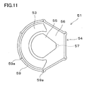
- the lid portion 55 is substantially circular or fan-shaped, and has an arcuate contour on the first side 53 c side above the optical window 53. That is, the lid part 55 is provided so as to extend indirectly from the first side 53c of the optical window 53 via the frame part 54a.
- the wall portion 56 corresponds to the side surface of the truncated cone of the main exterior portion 51, has a boundary with the lid portion 55 on the + Z side, and is adjacent to the first side 53 c of the optical window 53 and the third and fourth sides. There is a boundary extending linearly between the frame portion 54a on the 53g, 53h side. That is, the wall portion 56 is provided so as to extend indirectly from the third and fourth sides 53g and 53h of the optical window 53 via the frame portion 54a.
- the holding part 54 has a gate part 57 accompanying molding at a position relatively distant from the optical window 53.
- the gate portion 57 is desirably formed at a position symmetrical to the optical window 53, that is, a position along the center line extending in the X direction.
- the gate portion 57 When the gate portion 57 is close to the optical window 53, the surface shape is deformed due to distortion of the gate portion at the time of molding. Therefore, it is desirable that the gate portion 57 be separated from the gate size by 10 times or more. For example, when the gate diameter is ⁇ 1.5 mm, it is desirable that the gate diameter is 15 mm or more.
- the gate portion 57 is provided on the lid portion 55 of the holding portion 54. Specifically, it is provided at the approximate center of the lid 55. This is because the resin from the gate part 57 reaches the optical window 53 uniformly during molding, and maintains optically important transferability and thickness accuracy in the horizontal direction.
- the gate portion 57 and the lid portion 55 may be flush with each other without a step, or the gate portion 57 may protrude from the lid portion 55 in a convex shape. In either case, the position of the gate portion 57 can be determined from the gate mark.
- the holding part 54 that is, the frame part 54a, the lid part 55, and the wall part 56 have a light shielding part 58 that shields laser light and disturbance light so as to be adjacent to and surround the first optical surface 53a.
- the light shielding portion 58 is provided in a layered manner on the outer surface of the holding portion 54 excluding the optical window 53 in the main exterior portion 51.
- the light shielding portion 58 is formed by applying or vapor-depositing a material that shields laser light and disturbance light.
- a material of the light shielding portion 58 for example, a silicon-based or urethane-based material is used which is colored with an arbitrary color pigment such as white or black and has a light shielding property.
- An annular connection portion 59 is provided at the edge of the holding portion 54 (that is, the edge portion 51a of the main exterior portion 51) so as to be detachably connected to the sub exterior portion 52 which is a separate member.
- the connecting portion 59 extends flat along the XY plane, and a plurality of holes 59a through which fasteners (not shown) are provided at a plurality of locations of the connecting portion 59.
- the secondary exterior part 52 is a mating part to which the main exterior part 51 is attached, and houses the light projecting part 10, the light receiving part 20, the control part 40, and the like.
- the sub-exterior portion 52 is formed of, for example, a resin having a light shielding property, and this resin preferably has a linear expansion coefficient similar to that of the main exterior portion 51.
- the sub exterior portion 52 may be formed of the same resin as that of the main exterior portion 51. In this case, in order to ensure the light shielding property, the same material as the light shielding portion 58 is provided by coating or the like.
- the edge portion 52a of the sub-exterior portion 52 is also provided with a connecting portion for connecting to the main exterior portion 51, and there are a plurality of hole portions through which the fasteners are passed at positions corresponding to the hole portions 59a. Is provided.
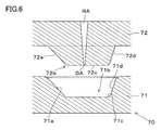
- the mold 70 includes a first mold 71 and a second mold 72.
- the first mold 71 is a fixed mold and the second mold 72 is a movable mold.
- the transfer surface of the mold 70 is obtained by inverting the molding surface of the main exterior portion 51 that is a molded product.
- the first mold 71 and the second mold 72 are mold-matched at the mold-matching surface PL to form a molding space 70a between the molds 71 and 72 (see FIG. 3C).
- a first window transfer portion 71a and a first holding transfer portion 71b for transferring the shape of the front side, that is, the outer side of the main exterior portion 51 are formed on the first mold 71 so as to face the molding space 70a. Yes.
- the first window transfer portion 71a is for transferring the shape of the first optical surface 53a of the optical window 53, and has a curved transfer surface and a mirror surface.
- the first holding / transfer unit 71b is for transferring the shape of the front side of the holding unit 54, the first lid transferring unit 71c for transferring the shape of the lid 55, and the first for transferring the shape of the wall 56.
- a wall transfer portion 71d is formed, and a frame transfer portion for transferring the shape of the frame portion 54a is also formed.
- the second mold 72 is formed with a second window transfer portion 72a and a second holding transfer portion 72b for transferring the shape on the back side, that is, the inner side of the main exterior portion 51.
- the second window transfer unit 72a transfers the shape of the second optical surface 53b of the optical window 53, and has a curved transfer surface and a mirror surface.
- the second holding transfer unit 72b is for transferring the shape of the back side of the holding unit 54, and is a second lid transfer unit 72c that transfers the shape of the lid 55, and a second that transfers the shape of the wall 56.
- a wall transfer portion 72d is formed, and a frame transfer portion for transferring the shape of the frame portion 54a is also formed.
- the first and second window transfer portions 71a and 72a have a first side A1 and a second side A2 that have a curvature and face each other along a contour.
- the radius of curvature of the first side A1 is different from the radius of curvature of the second side A2, and the surfaces or transfer surfaces of the first and second window transfer portions 71a, 72a are the reference axes TX of the exterior component 50 (that is, the first and second sides). It has a gradient with respect to the reference axes of the second holding transfer portions 71b and 72b.
- the first holding transfer portion 71b is provided with a gate GA communicating with the molding space 70a at a position relatively distant from the first window transfer portion 71a (for example, 10 mm or more).
- the gate GA is provided in the first lid transfer portion 71c that extends indirectly from the first side A1 via the frame transfer portion in the first holding transfer portion 71b. Specifically, the gate GA is provided substantially at the center of the first lid transfer portion 71 c in the first holding transfer portion 71 b of the first mold 71. Thus, it is preferable that the gate GA is disposed at the same distance from the first window transfer portion 71a. Thereby, the main exterior part 51 in which the injection pressure of the resin is uniformly applied and the thickness of the optical window 53 in the longitudinal direction is uniform can be manufactured.
- the gate GA is connected to a runner RA for supplying resin, a sprue (not shown), and the like, and the molten resin J from the sprue fills the runner RA and fills the molding space 70a via the gate GA.
- both molds 71 and 72 are heated to a temperature suitable for molding by a mold temperature controller (not shown).
- the hard coat treatment is performed by transfer or decoration using a film.
- the hard coat film 91 is fixed to the position corresponding to the first window transfer portion 71a of the first mold 71 by suction, pasting or the like.
- the hard coat film 91 for example, as shown in FIGS. 4A to 4D, two types of films are used depending on the molding method. Specifically, the hard coat layer 53e is formed by in-mold molding or insert molding. When only the hard coat film 93 is transferred by in-mold molding, as shown in FIG. 4A, a release layer 94 is provided between the film base 92 and the hard coat film 93, and the hard coat film 93 and the molding resin MC are provided.
- a film 91 having an adhesive layer 95 interposed therebetween As shown in FIG. 4B, after molding, only the hard coat layer 53e remains on the side of the molding resin MC by peeling off the film base 92.
- the release layer 94 is not provided, and the hard coat film 93 and the film base 92 are integrated.
- a film 91 having a configuration in which an adhesive layer 95 is interposed between the resin MC and the resin MC is used.
- the hard coat layer 53 e is integrated with the hard coat film 93 and the film base 92.
- the first mold 71 and the second mold 72 are matched. After mold matching, mold clamping is performed to clamp the first mold 71 and the second mold 72 with a necessary pressure.
- injection is performed by injecting molten resin J into the molding space 70a with a necessary pressure by an injection device (not shown).
- a resin for molding a resin having transparency in the wavelength region of the laser beam and preferably suppressing the transparency in the other wavelength region is used.
- the mold 70 maintains the resin pressure in the molding space 70a and slowly cools the molten resin J by heat dissipation.
- the semi-molded product MP including the runner portion 81 corresponding to the runner RA, the gate portion 57 corresponding to the gate GA, and the product portion 83 (original shape of the rear main exterior portion 51) corresponding to the molding space 70a. It is formed.
- mold opening is performed to retract the second mold 72 on the movable side.
- a stripper plate (not shown) is separated from the first mold 71 on the fixed side, and as a result, the gate portion 57 is cut from the semi-molded product MP.
- the first mold 71 and the second mold 72 are separated from each other.
- the product portion 83 is released from the first mold 71 while being held by the second mold 72. .
- the product portion 83 is projected by an ejector pin (not shown). As a result, the product portion 83 is pushed out toward the first mold 71 and released from the second mold 72.
- the product portion 83 is a resin molded product in which the optical window 53 and the holding portion 54 are integrated.
- the hard coat layer 53e is also in close contact with and integrated with the product portion 83 on the first optical surface 53a of the optical window 53 during molding. Thereby, even if the optical window 53 has a complicated shape, the hard coat layer 53e can be provided uniformly.
- the optical window 53 and the holding unit 54 are both light transmissive, it is necessary to perform a light shielding process on the holding unit 54 in a later step.
- an antireflection layer 53 f is formed on the optical window 53 of the product portion 83.
- the antireflection layer 53f is preferably formed on both surfaces of the first and second optical surfaces 53a and 53b.
- the antireflection layer 53f is uniformly formed on the entire surface of the optical window 53, but may be formed so as to protrude to the holding portion 54 side.
- the antireflection treatment is performed by transfer or decoration using a film, vapor deposition, sputtering, coating, or the like.
- the antireflection treatment may be an optical method in which a plurality of layers having different refractive indexes are formed, or a moth-eye structure having fine irregularities.
- direct film formation on a molded product by vapor deposition or coating may be performed, or a complex treatment using an antireflection functional film may be used.
- a method using a film a three-dimensional laminate for decorating the film on a molded product may be used, or the antireflection layer 53f may be formed by hot stamping using a transfer film, or an adhesive / adhesive is applied.
- the formed film may be attached to a molded product.
- the film on the first optical surface 53a side in that case may be prepared in a configuration having the antireflection layer 53f on the hard coat layer 53e described above (see FIGS. 10A and 10B).
- the shading part 58 is formed in the holding part 54 of the product part 83.
- FIG. 5B after mask MA is formed on the first optical surface 53a of the optical window 53, laser light or disturbance light is applied to the outer surface of the holding portion 54 as shown in FIG. 5C. Paint the material to be shielded from light.
- a polyethylene masking film is used as the mask MA.
- a masking film such as polypropylene or polyester may be used according to the application.
- the light shielding portion 58 is formed on the entire holding portion 54 of the main exterior portion 51. After the light shielding process, the main exterior portion 51 is obtained by removing the mask MA from the optical window 53 as shown in FIG. 5D.
- the edge portion 51a of the main exterior portion 51 and the edge portion 52a of the sub-exterior portion 52 are positioned for dustproof and waterproofing. It fixes with fasteners, such as a bolt, through the sealing member formed with materials, such as fluororubber. Thereby, the laser sensor 100 is completed.
- the optical window 53 and the holding portion 54 of the exterior component 50 are an integrally molded product of resin, it is not necessary to join the optical window 53 to the holding portion 54 separately. There is no bonding layer between 53 and the holding part 54. Therefore, there is no influence on the surface shape of the optical window 53, it is excellent in dustproof and waterproof properties, and maintenance is easy. Although it is necessary to join the main exterior part 51 with the sub-exterior part 52 which is a mating part, this joining does not affect the optical surfaces 53a and 53b of the optical window 53 and can be attached and detached with a bolt or the like using a seal member. Assembly is possible.
- the exterior component 50 of the laser sensor 100 has relatively high rigidity, and less variation in shape due to shrinkage and deformation at the time of molding.
- the optical window 53 is provided. Furthermore, by integrating the optical window 53 and the holding portion 54, structural or shape restrictions are reduced as compared with the case where the optical window 53 is separately joined, and the laser sensor 100 can be reduced in weight and size. Can do.
- the optical window 53 of the exterior component 50 is required to have high shape accuracy in order to project and receive light at a target location.
- a shape error occurs due to the contact condition of the jig, so the processing accuracy does not come out and variation occurs, High-precision R-shaped machining is difficult. This is particularly because the radius of curvature differs between the upper side of the optical window (corresponding to the first side 53c of the present embodiment) and the lower side (corresponding to the second side 53d of the present embodiment), and the optical surface is the exterior part. This is noticeable when there is a gradient with respect to the reference axis.
- the optical window has a U-shaped shape, so the rigidity is low, so the shape varies due to shrinkage or mold release after molding, and an error occurs in the R shape.
- the rigidity of the produced optical window is low, so it is difficult to hold it without deformation for evaluation of parts, and deformation occurs when measured by a contact method. Quality control is difficult.
- the exterior component 50 is used outdoors for monitoring purposes, it is required to have weather resistance and dustproof and waterproof properties against sunlight and rain.
- a component to which the optical window is attached is joined with an adhesive or the like, there is a problem that the surface shape of the optical window is distorted by the stress.
- the optical window and the component to which the optical window is attached are joined, if there is an error between the shape of the optical window and the shape of the counterpart component, a portion that does not mesh is generated.
- the optical surface is deformed by distortion caused by an adhesive or the like.
- the optical window 53 and the holding portion 54 are formed as an integral molded product of resin.
- a highly accurate optical window 53 is provided while ensuring dustproof and waterproof properties.
- the exterior component manufacturing method and the like according to the second embodiment is a partial modification of the exterior component manufacturing method and the like according to the first embodiment, and items not specifically described are the same as those of the first embodiment. .
- the first mold 71 is a movable mold
- the second mold 72 is a fixed mold. That is, the configuration of the mold 70 described in the first embodiment is reversed, and the gate GA is provided on the second mold 72 side. Therefore, in the main exterior part 51 to be molded, the gate part 57 is formed substantially at the center of the back surface of the holding part 54 lid part 55.
- the manufacturing method of the exterior component according to the third embodiment is a partial modification of the manufacturing method of the exterior component of the first embodiment, and the matters not specifically described are the same as those of the first embodiment. .
- the manufacturing method of the exterior component of this embodiment will be described.
- the molding process and the hard processing process are performed in parallel, but in the present embodiment, the hard coat processing process is performed after the molding process.
- FIG. 7A a mold 70 similar to that of the first embodiment is prepared, and as shown in FIG. 7B, the first and second molds 71 and 72 are clamped and molded. The molten resin J is injected into the space 70a. Thereafter, as shown in FIG. 7C, the first and second molds 71 and 72 are separated from each other, and the product portion 83 is taken out.
- a hard coat layer 53e is formed on the optical window 53 of the product portion 83 shown in FIG. 8A.
- the hard coat layer 53e is uniformly formed on the entire surface of the first optical surface 53a, but may be formed so as to protrude to the holding portion 54 side, or may be formed in the entire region including the inner second optical surface 53b. Also good.
- the hard coat treatment is performed by transfer or decoration using a hard coat film, application of a hard coat solution, or the like. When performing transfer or decoration using a film, the hard coat film 91 used in the first embodiment can be used (see FIGS. 4A to 4D).
- a three-dimensional laminate for decorating a film on a molded product may be used, or a hard coat layer 53e may be formed by a hot stamp using a transfer film, or an adhesive / adhesive is applied.
- the formed film may be attached to a molded product.
- the application method may be selected according to a shape such as a dip method, a spray method, or a spin method.
- an antireflection layer 53 f is formed on the optical window 53 of the product portion 83.
- the antireflection layer 53f is preferably formed on both surfaces of the first and second optical surfaces 53a and 53b.
- the antireflection layer 53f is uniformly formed on the entire surface of the optical window 53, but may be formed so as to protrude to the holding portion 54 side.
- the antireflection treatment is performed by transfer or decoration using a film, vapor deposition, sputtering, coating, or the like.
- the shading part 58 is formed in the holding part 54 of the product part 83.
- FIG. 8B after mask MA is formed on the first optical surface 53a of the optical window 53, laser light or disturbance light is applied to the outer surface of the holding portion 54 as shown in FIG. 8C. Paint the material to be shielded from light.
- the light shielding portion 58 is formed on the entire holding portion 54 of the main exterior portion 51.
- the main exterior portion 51 is obtained by removing the mask MA from the optical window 53 as shown in FIG. 8D.
- the laser sensor 100 includes a light projecting unit 10, a light receiving unit 20, a rotary reflection unit 30, a control unit 40, and an exterior component 50, as in the first embodiment.
- the reflecting mirror 31 of the rotary reflecting unit 30 of the present embodiment is a twice-reflecting polygon mirror, and includes a first reflecting unit 31a and a second reflecting unit 31b for bending an optical path.
- the first and second reflecting portions 31a and 31b are respectively arranged up and down along a rotation axis RX extending in parallel with the Z direction.
- the first and second reflecting portions 31a and 31b have a pyramid shape and are substantially symmetric with respect to their boundary portions.
- the mirror surface of the first reflecting portion 31a is inclined with respect to the Z axis, and reflects the laser beam L1 incident from the + X direction, which is the left direction on the paper surface, in a direction substantially orthogonal to the paper surface. Then, the light is guided to the mirror surface of the upper second reflecting portion 31b.
- the mirror surface of the second reflecting portion 31b is inclined with respect to the Z axis, reflects the laser beam L1 incident from the ⁇ Z direction, which is the downward direction on the paper surface, in a direction substantially orthogonal to the left surface on the paper surface. Guide to the detection target OB side.
- a part of the reflected light L2 reflected by the detection target OB follows a path opposite to the path of the laser light L1, and is detected by the light receiving unit 20. That is, the reflecting mirror 31 reflects the reflected light L2 reflected by the detection target OB, that is, the return light again by the mirror surface of the second reflecting portion 31b and guides it to the mirror surface of the first reflecting portion 31a. Subsequently, the reflected light L2 is reflected again by the mirror surface of the first reflecting portion 31a and guided to the light receiving portion 20 side.
- the reflecting mirror 31 rotates, the traveling direction of the laser light L1 changes in a plane orthogonal to the Z-axis direction (that is, the XY plane).
- the laser beam L1 is scanned along the Y-axis direction as the reflecting mirror 31 rotates.
- An angle area scanned by the laser beam L1 is a detection area. Since the rotary reflection unit 30 of the present embodiment is a twice reflection type, the detection region in the Z-axis direction is wider than that of the once reflection type.
- the hard coat treatment process is performed in parallel with the molding process, but the hard coat treatment process and the antireflection treatment process may be performed in parallel with the molding process.
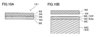
- a film 191 as shown in FIGS. 10A and 10B is used.
- an antireflection film 96 is provided on a hard coat film 93, and a release layer 94 and a film substrate 92 are provided thereon.
- a film 191 is used.
- FIG. 10A an antireflection film 96 is provided on a hard coat film 93, and a release layer 94 and a film substrate 92 are provided thereon.
- the hard coat layer 53e and the antireflection layer 53f are formed on the molding resin MC.
- the antireflection treatment using such a film can also be applied to the second optical surface 53b of the optical window 53.
- the hard coat film 93 is removed from the film 191 shown in FIGS. 10A and 10B as the film. What is necessary is just to use.
- the film 91 shown in FIGS. 4C and 4D is provided with an antireflection film on the hard coat film 93.
- the light shielding process, the hard coat process, and the antireflection process may be performed in reverse. That is, in the light shielding process, after coating the optical window 53 with the mask MA, the mask MA is removed and the hard coat process and the antireflection process are performed.
- the built-in components of the laser sensor 100 and the arrangement thereof can be changed as appropriate.
- a folding mirror that bends the optical paths of the laser light L1 and the reflected light L2 may be provided between the rotary reflection unit 30 and the optical window 53.
- an optical filter or the like may be provided in front of the sensor.
- a light shielding member may be provided around the light receiving unit 20.
- the lid portion 55 of the main exterior portion 51 extends from the lower side of the exterior component 50, that is, from the second side 53 d of the optical window 53.
- the structure or shape of the main exterior part 51 and the subexterior part 52 can be changed suitably.
- the main exterior part 51 is composed of only the optical window 53 and the lid part 55, only the optical window 53 and the wall part 56, the optical window 53 and the frame part 54a. It is good also as a structure of only.
- the holding portion 54 may have a truncated cone shape. Moreover, it is good also as a structure directly attached to the part which attaches the laser sensor 100 as another member, without using the subexterior part 52. FIG.
- the position of the gate portion 57 is provided at the approximate center of the lid portion 55 of the holding portion 54.
- it may be provided at another position. For example, you may provide in the position further away from the optical window 53 of the cover part 55, the position facing the optical window 53 of the wall part 56, etc., as shown in FIG.
- the configuration of the mold 70 in the above embodiment can be configured as shown in FIG. Specifically, in the second mold 72 on the movable side, a suction pipe 73a connected to an air vent (air escape groove) V in contact with the product shape is provided, so that the air in the mold 70 and the gas from the molten resin J are supplied. The molten resin J can be easily introduced into the molding space 70a. Further, in the second mold 72 on the movable side, an ejector 73b for facilitating removal of the product part 83 can be provided.
- the ejector 73b is provided with a plurality of ejector pins 73c at positions corresponding to the peripheral portion of the gate portion 57 of the lid portion 55 of the product portion 83 (that is, the main exterior portion 51) and at positions corresponding to the connecting portion 59. .
- the anti-reflection film 91 is fixed to the first mold 71 by suction or pasting.
- the suction pipe 74 a is attached to the first mold 71 on the fixed side, for example. It may be provided to adsorb the film 91.
- the film 91 may be guided to the first window transfer portion 71a using the arm 75 or the like.
- the lens was provided in the light projection part 10 and the light-receiving part 20, the structure of the light projection part 10 and the light-receiving part 20 can be changed suitably.
Landscapes
- Engineering & Computer Science (AREA)
- Physics & Mathematics (AREA)
- General Physics & Mathematics (AREA)
- Computer Networks & Wireless Communication (AREA)
- Radar, Positioning & Navigation (AREA)
- Remote Sensing (AREA)
- Electromagnetism (AREA)
- Injection Moulding Of Plastics Or The Like (AREA)
- Moulds For Moulding Plastics Or The Like (AREA)
- Optical Radar Systems And Details Thereof (AREA)
- Length Measuring Devices By Optical Means (AREA)
Abstract
Priority Applications (4)
| Application Number | Priority Date | Filing Date | Title |
|---|---|---|---|
| EP16899417.6A EP3447521B1 (fr) | 2016-04-20 | 2016-04-20 | Capteur laser et procédé de fabrication d'un constituant extérieur |
| JP2018512712A JP6802531B2 (ja) | 2016-04-20 | 2016-04-20 | レーザーセンサー及び外装部品の製造方法 |
| PCT/JP2016/062574 WO2017183145A1 (fr) | 2016-04-20 | 2016-04-20 | Capteur laser et procédé de fabrication d'un constituant extérieur |
| US16/094,361 US10704894B2 (en) | 2016-04-20 | 2016-04-20 | Laser sensor and manufacturing method for exterior component |
Applications Claiming Priority (1)
| Application Number | Priority Date | Filing Date | Title |
|---|---|---|---|
| PCT/JP2016/062574 WO2017183145A1 (fr) | 2016-04-20 | 2016-04-20 | Capteur laser et procédé de fabrication d'un constituant extérieur |
Publications (1)
| Publication Number | Publication Date |
|---|---|
| WO2017183145A1 true WO2017183145A1 (fr) | 2017-10-26 |
Family
ID=60116840
Family Applications (1)
| Application Number | Title | Priority Date | Filing Date |
|---|---|---|---|
| PCT/JP2016/062574 Ceased WO2017183145A1 (fr) | 2016-04-20 | 2016-04-20 | Capteur laser et procédé de fabrication d'un constituant extérieur |
Country Status (4)
| Country | Link |
|---|---|
| US (1) | US10704894B2 (fr) |
| EP (1) | EP3447521B1 (fr) |
| JP (1) | JP6802531B2 (fr) |
| WO (1) | WO2017183145A1 (fr) |
Cited By (7)
| Publication number | Priority date | Publication date | Assignee | Title |
|---|---|---|---|---|
| JP2019133153A (ja) * | 2018-01-30 | 2019-08-08 | ヴァイアヴィ・ソリューションズ・インコーポレイテッドViavi Solutions Inc. | 光学的特性及び機械的特性を有する光学デバイス |
| EP3525007A1 (fr) * | 2018-02-10 | 2019-08-14 | Aptiv Technologies Limited | Enceinte |
| WO2020195247A1 (fr) * | 2019-03-28 | 2020-10-01 | 豊田合成株式会社 | Couvercle de capteur infrarouge |
| JP2020165943A (ja) * | 2019-03-28 | 2020-10-08 | 豊田合成株式会社 | 赤外線センサ用カバー |
| JP2021162353A (ja) * | 2020-03-30 | 2021-10-11 | 日鉄テックスエンジ株式会社 | センサ保護カバー |
| US20230251353A1 (en) * | 2022-02-07 | 2023-08-10 | Riegl Laser Measurement Systems Gmbh | Laser Scanner |
| US12578519B2 (en) | 2020-03-05 | 2026-03-17 | Viavi Solutions Inc. | Optical coating for organic surface treatments |
Families Citing this family (5)
| Publication number | Priority date | Publication date | Assignee | Title |
|---|---|---|---|---|
| CN111381236A (zh) * | 2020-04-24 | 2020-07-07 | 森思泰克河北科技有限公司 | 透光窗口及激光雷达 |
| US20210356563A1 (en) * | 2020-05-13 | 2021-11-18 | Beijing Voyager Technology Co., Ltd. | Light detection and ranging system with polygon shaped enclosure |
| US11733356B2 (en) * | 2020-08-14 | 2023-08-22 | Ford Global Technologies, Llc | Sensor apparatus with drainage |
| US12196864B1 (en) * | 2021-07-22 | 2025-01-14 | Robotic Research Opco, Llc | Detection and ranging sensor stabilization systems and methods |
| US20240263939A1 (en) * | 2023-02-07 | 2024-08-08 | Keyence Corporation | Probe for three-dimensional scanner and three-dimensional scanner |
Citations (6)
| Publication number | Priority date | Publication date | Assignee | Title |
|---|---|---|---|---|
| JP2005055226A (ja) * | 2003-07-31 | 2005-03-03 | Hokuyo Automatic Co | スキャニング型レンジセンサ |
| JP2006349449A (ja) * | 2005-06-15 | 2006-12-28 | Hokuyo Automatic Co | 走査型レンジセンサ |
| JP2008282021A (ja) * | 2008-05-26 | 2008-11-20 | Ricoh Co Ltd | 光走査装置および画像形成装置 |
| JP2011141261A (ja) | 2009-12-08 | 2011-07-21 | Denso Wave Inc | レーザレーダ装置 |
| JP2015081769A (ja) * | 2013-10-21 | 2015-04-27 | シャープ株式会社 | 光学式物体位置検出装置 |
| JP2015215282A (ja) | 2014-05-13 | 2015-12-03 | 株式会社リコー | 物体検出装置及びセンシング装置 |
Family Cites Families (9)
| Publication number | Priority date | Publication date | Assignee | Title |
|---|---|---|---|---|
| US5706140A (en) * | 1993-09-06 | 1998-01-06 | Kansei Corp. | Optical distance measuring equipment |
| TWI326243B (en) * | 2003-03-25 | 2010-06-21 | Nissha Printing | A method for production of an in-mold decorated product in injection molding and a mold for in-mold decorating in injection molding |
| JP3908226B2 (ja) * | 2004-02-04 | 2007-04-25 | 日本電産株式会社 | スキャニング型レンジセンサ |
| JP5181628B2 (ja) * | 2007-11-12 | 2013-04-10 | 株式会社デンソーウェーブ | レーザレーダ装置 |
| US8692980B2 (en) * | 2010-11-01 | 2014-04-08 | Advanced Scientific Concepts, Inc. | Flash LADAR collision avoidance system |
| JP5532003B2 (ja) * | 2011-03-31 | 2014-06-25 | 株式会社デンソーウェーブ | レーザレーダ装置 |
| EP2746808B1 (fr) * | 2012-12-18 | 2015-02-25 | Sick Ag | Capteur optoélectronique destiné à la détection d'objets |
| US9746349B2 (en) * | 2013-09-02 | 2017-08-29 | Heptagon Micro Optics Pte. Ltd. | Opto-electronic module including a non-transparent separation member between a light emitting element and a light detecting element |
| US10061021B2 (en) * | 2016-07-06 | 2018-08-28 | Datalogic IP Tech, S.r.l. | Clutter filter configuration for safety laser scanner |
-
2016
- 2016-04-20 US US16/094,361 patent/US10704894B2/en active Active
- 2016-04-20 EP EP16899417.6A patent/EP3447521B1/fr active Active
- 2016-04-20 JP JP2018512712A patent/JP6802531B2/ja active Active
- 2016-04-20 WO PCT/JP2016/062574 patent/WO2017183145A1/fr not_active Ceased
Patent Citations (6)
| Publication number | Priority date | Publication date | Assignee | Title |
|---|---|---|---|---|
| JP2005055226A (ja) * | 2003-07-31 | 2005-03-03 | Hokuyo Automatic Co | スキャニング型レンジセンサ |
| JP2006349449A (ja) * | 2005-06-15 | 2006-12-28 | Hokuyo Automatic Co | 走査型レンジセンサ |
| JP2008282021A (ja) * | 2008-05-26 | 2008-11-20 | Ricoh Co Ltd | 光走査装置および画像形成装置 |
| JP2011141261A (ja) | 2009-12-08 | 2011-07-21 | Denso Wave Inc | レーザレーダ装置 |
| JP2015081769A (ja) * | 2013-10-21 | 2015-04-27 | シャープ株式会社 | 光学式物体位置検出装置 |
| JP2015215282A (ja) | 2014-05-13 | 2015-12-03 | 株式会社リコー | 物体検出装置及びセンシング装置 |
Cited By (17)
| Publication number | Priority date | Publication date | Assignee | Title |
|---|---|---|---|---|
| JP2023100706A (ja) * | 2018-01-30 | 2023-07-19 | ヴァイアヴィ・ソリューションズ・インコーポレイテッド | 光学的特性及び機械的特性を有する光学デバイス |
| JP2019133153A (ja) * | 2018-01-30 | 2019-08-08 | ヴァイアヴィ・ソリューションズ・インコーポレイテッドViavi Solutions Inc. | 光学的特性及び機械的特性を有する光学デバイス |
| JP2025028999A (ja) * | 2018-01-30 | 2025-03-05 | ヴァイアヴィ・ソリューションズ・インコーポレイテッド | 光学的特性及び機械的特性を有する光学デバイス |
| US12174342B2 (en) | 2018-01-30 | 2024-12-24 | Viavi Solutions Inc. | Optical device having optical and mechanical properties |
| JP2021177240A (ja) * | 2018-01-30 | 2021-11-11 | ヴァイアヴィ・ソリューションズ・インコーポレイテッドViavi Solutions Inc. | 光学的特性及び機械的特性を有する光学デバイス |
| US11360242B2 (en) | 2018-01-30 | 2022-06-14 | Viavi Solutions Inc. | Optical device having optical and mechanical properties |
| JP7268086B2 (ja) | 2018-01-30 | 2023-05-02 | ヴァイアヴィ・ソリューションズ・インコーポレイテッド | 光学的特性及び機械的特性を有する光学デバイス |
| EP3525007A1 (fr) * | 2018-02-10 | 2019-08-14 | Aptiv Technologies Limited | Enceinte |
| CN110161482A (zh) * | 2018-02-10 | 2019-08-23 | 德尔福技术有限公司 | 封壳 |
| US10627487B2 (en) | 2018-02-10 | 2020-04-21 | Delphi Technologies, Llc | Enclosure |
| WO2020195247A1 (fr) * | 2019-03-28 | 2020-10-01 | 豊田合成株式会社 | Couvercle de capteur infrarouge |
| JP7484163B2 (ja) | 2019-03-28 | 2024-05-16 | 豊田合成株式会社 | 赤外線センサ用カバー |
| JP2020165943A (ja) * | 2019-03-28 | 2020-10-08 | 豊田合成株式会社 | 赤外線センサ用カバー |
| US12578519B2 (en) | 2020-03-05 | 2026-03-17 | Viavi Solutions Inc. | Optical coating for organic surface treatments |
| JP7364520B2 (ja) | 2020-03-30 | 2023-10-18 | 日鉄テックスエンジ株式会社 | センサ保護カバー |
| JP2021162353A (ja) * | 2020-03-30 | 2021-10-11 | 日鉄テックスエンジ株式会社 | センサ保護カバー |
| US20230251353A1 (en) * | 2022-02-07 | 2023-08-10 | Riegl Laser Measurement Systems Gmbh | Laser Scanner |
Also Published As
| Publication number | Publication date |
|---|---|
| EP3447521B1 (fr) | 2019-12-18 |
| US20190137259A1 (en) | 2019-05-09 |
| US10704894B2 (en) | 2020-07-07 |
| JP6802531B2 (ja) | 2020-12-16 |
| EP3447521A1 (fr) | 2019-02-27 |
| EP3447521A4 (fr) | 2019-02-27 |
| JPWO2017183145A1 (ja) | 2019-02-28 |
Similar Documents
| Publication | Publication Date | Title |
|---|---|---|
| JP6802531B2 (ja) | レーザーセンサー及び外装部品の製造方法 | |
| US11358173B2 (en) | Method for manufacturing a transparent vehicle part | |
| CN111527009A (zh) | 用于机动车辆的前格栅的雷达透明装饰板 | |
| JP6234676B2 (ja) | レンズユニット | |
| CN101354447A (zh) | 光学元件 | |
| RU2734640C1 (ru) | Установочный элемент для транспортного средства с интегрированным модулем камеры | |
| CN110050220A (zh) | 显示部件、抬头显示器装置以及显示部件的制造方法 | |
| CN101352908A (zh) | 光学元件的制造方法 | |
| WO2007007755A1 (fr) | Organe de formage d'une structure anti-reflechissante et materiau de transfert l'utilisant, et appareil optique muni de cette structure anti-reflechissante ainsi que procede pour sa production | |
| KR100867520B1 (ko) | 결상 렌즈 및 그 제조 방법 | |
| US11193831B2 (en) | Method for manufacturing near-infrared sensor cover | |
| CN112781006A (zh) | 透明车辆部件的制造方法 | |
| JP5125271B2 (ja) | 反射スクリーンの製造方法および反射スクリーン | |
| JP2009015196A (ja) | 反射スクリーンの製造方法および反射スクリーン | |
| CN111076660A (zh) | 机器视觉系统的目标靶单元、目标靶组件和机器视觉系统 | |
| WO2017199609A1 (fr) | Élément de revêtement et filtre de transfert | |
| US11305312B2 (en) | Method for manufacturing a transparent vehicle part | |
| WO2019172211A1 (fr) | Procédé de fabrication d'article moulé | |
| EP4261611B1 (fr) | Couvercle pour un système d'éclairage et d'imagerie et système d'éclairage et d'imagerie associé | |
| JP4036924B2 (ja) | 複合型レンズ | |
| US10259205B2 (en) | Vehicular resin glass | |
| JP2018010805A (ja) | 車両用灯具及び車両用灯具の製造方法 | |
| JP6761231B2 (ja) | 反射防止微細構造体、光学フィルタ、光学装置、及び反射防止微細構造体の製造方法 | |
| CN110109207A (zh) | 一种多色感光雷达镀膜结构及镀膜方法 | |
| US20240262060A1 (en) | Method for producing a lens for a lamp, lens, lamp and motor vehicle |
Legal Events
| Date | Code | Title | Description |
|---|---|---|---|
| ENP | Entry into the national phase |
Ref document number: 2018512712 Country of ref document: JP Kind code of ref document: A |
|
| NENP | Non-entry into the national phase |
Ref country code: DE |
|
| WWE | Wipo information: entry into national phase |
Ref document number: 2016899417 Country of ref document: EP |
|
| ENP | Entry into the national phase |
Ref document number: 2016899417 Country of ref document: EP Effective date: 20181120 |
|
| 121 | Ep: the epo has been informed by wipo that ep was designated in this application |
Ref document number: 16899417 Country of ref document: EP Kind code of ref document: A1 |