WO2017183157A1 - Scanner à fibre optique, dispositif d'éclairage et dispositif d'observation - Google Patents
Scanner à fibre optique, dispositif d'éclairage et dispositif d'observation Download PDFInfo
- Publication number
- WO2017183157A1 WO2017183157A1 PCT/JP2016/062650 JP2016062650W WO2017183157A1 WO 2017183157 A1 WO2017183157 A1 WO 2017183157A1 JP 2016062650 W JP2016062650 W JP 2016062650W WO 2017183157 A1 WO2017183157 A1 WO 2017183157A1
- Authority
- WO
- WIPO (PCT)
- Prior art keywords
- optical fiber
- elastic member
- fitting portion
- piezoelectric element
- piezoelectric elements
- Prior art date
- Legal status (The legal status is an assumption and is not a legal conclusion. Google has not performed a legal analysis and makes no representation as to the accuracy of the status listed.)
- Ceased
Links
Images


Classifications
-
- A—HUMAN NECESSITIES
- A61—MEDICAL OR VETERINARY SCIENCE; HYGIENE
- A61B—DIAGNOSIS; SURGERY; IDENTIFICATION
- A61B1/00—Instruments for performing medical examinations of the interior of cavities or tubes of the body by visual or photographical inspection, e.g. endoscopes; Illuminating arrangements therefor
-
- G—PHYSICS
- G02—OPTICS
- G02B—OPTICAL ELEMENTS, SYSTEMS OR APPARATUS
- G02B23/00—Telescopes, e.g. binoculars; Periscopes; Instruments for viewing the inside of hollow bodies; Viewfinders; Optical aiming or sighting devices
- G02B23/24—Instruments or systems for viewing the inside of hollow bodies, e.g. fibrescopes
- G02B23/26—Instruments or systems for viewing the inside of hollow bodies, e.g. fibrescopes using light guides
-
- G—PHYSICS
- G02—OPTICS
- G02B—OPTICAL ELEMENTS, SYSTEMS OR APPARATUS
- G02B26/00—Optical devices or arrangements for the control of light using movable or deformable optical elements
- G02B26/08—Optical devices or arrangements for the control of light using movable or deformable optical elements for controlling the direction of light
- G02B26/10—Scanning systems
-
- H—ELECTRICITY
- H10—SEMICONDUCTOR DEVICES; ELECTRIC SOLID-STATE DEVICES NOT OTHERWISE PROVIDED FOR
- H10N—ELECTRIC SOLID-STATE DEVICES NOT OTHERWISE PROVIDED FOR
- H10N30/00—Piezoelectric or electrostrictive devices
- H10N30/20—Piezoelectric or electrostrictive devices with electrical input and mechanical output, e.g. functioning as actuators or vibrators
Definitions
- the present invention relates to an optical fiber scanner, an illumination device, and an observation device.
- Patent Document 1 an optical fiber is inserted in a longitudinal direction into a through hole of a cylindrical piezoelectric element.
- the present invention has been made in view of the above-described circumstances, and an object thereof is to provide an optical fiber scanner capable of easily performing an assembling operation, and an illumination device and an observation device including the same.
- an optical fiber having a longitudinal axis and emitting light from a distal end portion, and a position of the optical fiber at a position closer to the proximal end portion of the optical fiber than the distal end portion of the optical fiber.
- An elastic member that is fixed to the outer peripheral surface and covers a part of the optical fiber in the longitudinal direction; a piezoelectric element that is fixed to the outer surface of the elastic member and expands and contracts in the longitudinal direction of the optical fiber by application of voltage; and the elastic member
- An optical fiber scanner comprising: a fitting portion formed from a distal end surface to a proximal end surface, having an opening on a radially outer side of the optical fiber, and having a portion of the longitudinal direction of the optical fiber disposed therein.
- the piezoelectric element when a voltage is applied to the piezoelectric element, the piezoelectric element is deformed in the longitudinal direction of the optical fiber, and the elastic member and the optical fiber to which the piezoelectric element is fixed are bent and deformed.
- the tip of the optical fiber is displaced in the radial direction. Thereby, the light emitted from the tip of the optical fiber can be scanned.
- the fitting portion of the elastic member in which the optical fiber is disposed opens not only on the distal end side and the proximal end side of the elastic member but also on the radially outer side. Accordingly, in the assembly process of the optical fiber scanner, the optical fiber and the elastic member can be easily assembled by fitting the optical fiber into the fitting portion through the opening in the radial direction instead of the longitudinal direction. .
- the opening of the fitting portion may have a width larger than the diameter dimension of the optical fiber in a direction orthogonal to the longitudinal axis.
- a pressing member that is provided on the radially outer side of the fitting portion and covers the fitting portion in the width direction may be provided.
- a cylindrical shape is provided on the radially outer side of the optical fiber on the proximal end side than the piezoelectric element and is fixed to the elastic member, and has a larger outer diameter than the elastic member.
- a holding member is provided, the holding member communicates with the fitting portion of the elastic member in the longitudinal direction, has an opening on the same side as the fitting portion of the elastic member, and holds the optical fiber. You may provide the member side insertion part.
- the opening of the holding member side fitting portion may have a width larger than the diameter dimension of the optical fiber in a direction orthogonal to the longitudinal axis.
- the fitting portion may be a U-shaped groove having a substantially semicircular shape or a square groove having a quadrangular shape in a cross section intersecting the longitudinal direction.
- the elastic member may have a rectangular tube-like or substantially semi-cylindrical outer surface in which a part of the circumference is cut out in the longitudinal direction from the distal end to the proximal end.
- the piezoelectric element may be disposed so as to straddle the central axis of the optical fiber in the radial direction of the optical fiber.
- the three piezoelectric elements and the openings of the fitting portions are arranged at equal intervals in the circumferential direction of the optical fiber, and are opposed to the openings of the fitting portions in the radial direction.
- the thickness of the piezoelectric element arranged at the position may be larger than the thickness of the other two piezoelectric elements.
- the three piezoelectric elements and the openings of the fitting portions are arranged at equal intervals in the circumferential direction of the optical fiber, and are opposed to the openings of the fitting portions in the radial direction.
- the piezoelectric element arranged at the position may be made of a material having a large deformation amount with respect to the voltage as compared with the material forming the other two piezoelectric elements. By doing so, the optical fiber is bent and deformed in the first direction and the second direction orthogonal to each other by the single piezoelectric element facing the opening of the fitting portion and the other two piezoelectric elements. Is done.
- an illuminating apparatus including a light source that generates illumination light and an optical fiber scanner according to the first aspect in which a proximal end of the optical fiber is connected to the light source.
- the illumination device according to the second aspect, a light detection unit that detects return light that returns from the subject when the subject is irradiated with illumination light from the illumination device, and the piezoelectric device. And a voltage supply unit that supplies the voltage to the element.
- FIG. 1 is an overall configuration diagram of an observation apparatus including an optical fiber scanner and an illumination device according to an embodiment of the present invention. It is a longitudinal cross-sectional view along the longitudinal axis which shows the internal structure of the insertion part front-end
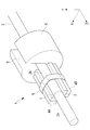
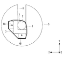
- FIG. 3 is a perspective view of the optical fiber scanner of FIG. 2. It is the front view which looked at the optical fiber scanner of Drawing 3A from the tip side in the direction of a longitudinal axis. It is the front view which looked at the modification of the optical fiber scanner of FIG. 2 from the front end side to the longitudinal axis direction. It is the front view which looked at the other modification of the optical fiber scanner of FIG. 2 from the front end side to the longitudinal axis direction.
- the observation apparatus 100 includes an endoscope 20 having an elongated insertion portion 20a, a control device main body 30 connected to the endoscope 20, and the control device main body 30. And a display 40 connected thereto.
- the observation apparatus 100 scans illumination light emitted from the distal end of the insertion portion 20a of the endoscope 20 along the spiral scanning locus B on the subject A, and acquires an image of the subject A. It is a mirror device.
- the observation device 100 includes a lighting device 10 that irradiates the subject A with illumination light, and a light detection device such as a photodiode that detects return light that returns from the subject A when the illumination light is irradiated. And a drive control device (voltage supply unit) 70 for driving and controlling the illumination device 10 and the photodetector 60.
- the photodetector 60 and the drive control device 70 are provided in the control device main body 30.
- the illuminating device 10 is provided in the control device main body 30 and generates an illuminating light.
- the illuminating device 10 is provided in the insertion portion 20a.
- the illuminating device 10 guides the illuminating light emitted from the light source 50 and emits it from the tip.
- An optical fiber scanner 1 having an optical fiber 2, a condensing lens 11 that is disposed on the tip side of the optical fiber 2 and collects illumination light emitted from the optical fiber 2, and the optical fiber scanner 1 and the condensing lens 11.
- a long and narrow cylindrical frame 12 that accommodates the light and a circumferential arrangement on the outer peripheral surface of the frame 12, and return light from the subject A (for example, reflected light or fluorescence of illumination light) is detected.
- a plurality of optical fibers for detection 13 that are guided to the device 60.
- the optical fiber scanner 1 includes an optical fiber 2, an elastic member 3 fixed to the outer peripheral surface of the optical fiber 2, and a plurality of sheets fixed to the outer surface of the elastic member 3.
- Piezoelectric elements 4A, 4B, and 4C, a holding member 5 that is provided on the optical fiber 2 on the proximal end side relative to the piezoelectric elements 4A, 4B, and 4C, and an elastic member 3 are provided.
- the holding member 6 is provided. In FIG. 2, the pressing member 6 is omitted.
- the optical fiber 2 is a multimode fiber or a single mode fiber, and is made of a cylindrical glass material having a longitudinal axis.
- a resin coating 2 b for reinforcing and protecting the optical fiber 2 is applied to the outer peripheral surface of the optical fiber 2.
- the optical fiber 2 shown in FIGS. 2 and 3A is provided with a resin coating 2b from the base end to the tip of the elastic member 3, but may be provided with a resin coating 2b from the base end to the tip.
- the optical fiber 2 is arranged along the longitudinal direction of the frame body 12 and extends from the base end of the frame body 12 to the control device main body 30.
- the distal end of the optical fiber 2 is disposed in the vicinity of the distal end portion inside the frame body 12, and the proximal end of the optical fiber 2 is connected to the light source 50 in the control device main body 30.
- the elastic member 3 is provided on the outer peripheral surface of the optical fiber 2 at a position closer to the proximal end portion of the optical fiber 2 than the distal end portion of the optical fiber 2.
- the distal end portion of the optical fiber 2 projecting from the distal end surface of the elastic member 3 to the distal end side is referred to as a protruding portion 2a.
- the elastic member 3 has a quadrangular prism shape having three flat side surfaces and one side surface on which the fitting portion 7 is formed.
- the fitting portion 7 is formed of a U-shaped groove having a substantially semicircular shape in a cross section orthogonal to the longitudinal direction of the elastic member 3, and is formed in the longitudinal direction over the entire length of the elastic member 3 from the distal end surface to the proximal end surface of the elastic member 3.
- the optical fiber 2 is disposed in the longitudinal direction in the fitting portion 7, and the inner surface of the fitting portion 7 and the outer peripheral surface of the optical fiber 2 are fixed to each other by an epoxy adhesive.
- the width dimension of the opening of the fitting portion 7 on the side surface of the elastic member 3 is equal to or larger than the diameter dimension of the optical fiber 2. Accordingly, the optical fiber 2 can be fitted into the fitting portion 7 in the radial direction.
- the depth dimension of the fitting part 7 (the dimension in the direction orthogonal to the side surface on which the fitting part 7 is formed) is larger than the radial dimension of the optical fiber 2. Therefore, the central axis of the optical fiber 2 fitted in the fitting part 7 is located in the fitting part 7.
- the elastic member 3 is made of a material having elasticity and high rigidity. Such a material is selected from, for example, metal (nickel, stainless steel, iron, aluminum alloy, titanium, etc.), synthetic resin (hard plastic), glass, and carbon. As will be described later, when the elastic member 3 is used as a common ground (GND), the elastic member 3 is made of a conductive metal material so that the elastic member 3 has conductivity at least on the surface, Alternatively, a film made of a conductive metal material is formed on the surface.
- GND common ground
- the piezoelectric elements 4A, 4B, 4C are rectangular flat plates made of a piezoelectric ceramic material such as lead zirconate titanate (PZT), for example.
- the piezoelectric elements 4A, 4B, and 4C are subjected to + electrode processing on the front surface and ⁇ electrode processing on the back surface, and are thus polarized in the thickness direction from the + pole toward the ⁇ pole.
- Arrows attached to the piezoelectric elements 4A, 4B, and 4C in the drawing indicate the polarization directions of the piezoelectric elements 4A, 4B, and 4C.
- Piezoelectric elements 4A, 4B, and 4C are fixed to each of three flat side surfaces of the four side surfaces of the elastic member 3 other than the side surface on which the fitting portion 7 is formed, with an epoxy adhesive. .
- the three piezoelectric elements 4 ⁇ / b> A, 4 ⁇ / b> B, 4 ⁇ / b> C and the openings of the fitting portions 7 are arranged at substantially equal intervals in the circumferential direction of the optical fiber 2.
- the longitudinal direction of the optical fiber 2 is defined as a Z direction
- two radial directions of the optical fiber 2 are defined as an X direction and a Y direction.
- the width direction of the fitting portion 7 is the X direction
- the depth direction of the fitting portion 7 is the Y direction.
- the three piezoelectric elements are composed of two piezoelectric elements 4A and 4C for the A phase (X direction) and one piezoelectric element 4B for the B phase (Y direction). As shown in FIG. 3B, the two A-phase piezoelectric elements 4A and 4C are arranged so that the polarization directions are parallel to the X direction and face the same side. The B-phase piezoelectric element 4B is arranged so that the polarization direction is parallel to the Y direction.
- the A-phase piezoelectric elements 4A and 4C are arranged so as to straddle the central axis of the optical fiber 2 in the Y direction, and the B-phase piezoelectric elements 4B are arranged so as to straddle the central axis of the optical fiber 2 in the X direction.
- a phase A lead wire (not shown) is connected to the two A phase piezoelectric elements 4A and 4C by a conductive adhesive, and a B phase piezoelectric element 4B is connected to the B phase lead.
- a wire (not shown) is connected by a conductive adhesive, and a GND lead wire (not shown) is connected to the holding member 5 by a conductive adhesive.
- the lead wires for A phase, B phase, and GND are connected to the drive control device 70 in the control device main body 30.
- the holding member 5 has a cylindrical shape having an outer dimension larger than that of the elastic member 3, and a fitting portion (holding member side fitting portion) 8 is formed in a part of the outer circumferential surface in the circumferential direction.
- the fitting portion 8 is formed of a U-shaped groove having a U-shaped inner surface in a cross section orthogonal to the longitudinal direction of the holding member 5, and extends in the longitudinal direction over the entire length of the holding member 5 from the distal end surface to the proximal end surface of the holding member 5. Is formed.
- the fitting part 8 is arranged in line with the fitting part 7 so as to communicate with the fitting part 7 in the longitudinal direction.
- the optical fiber 2 is disposed in the longitudinal direction in the fitting portion 8, and the inner surface of the fitting portion 8 and the outer peripheral surface of the optical fiber 2 are fixed to each other by an epoxy adhesive.
- the width dimension (dimension in the direction orthogonal to the longitudinal direction) of the opening of the fitting portion 8 on the outer peripheral surface of the holding member 5 is equal to or larger than the diameter dimension of the optical fiber 2. Accordingly, the optical fiber 2 can be fitted into the fitting portion 8 in the radial direction.
- the distal end surface of the holding member 5 is disposed in contact with the proximal end surface of the elastic member 3, and is fixed to the proximal end surface of the elastic member 3 by a conductive adhesive.
- the outer peripheral surface of the holding member 5 is fixed to the inner wall of the frame body 12.
- the optical fiber 2 may be provided with a metal coating on the outer peripheral surface instead of the resin coating. In this way, an epoxy adhesive or solder can be used for fixing the optical fiber 2 to the elastic member 3 and the holding member 5.
- the drive control device 70 applies an A-phase alternating voltage having a predetermined drive frequency to the piezoelectric elements 4A and 4C via the A-phase lead wire, and applies a predetermined voltage to the piezoelectric element 4B via the B-phase lead wire.
- a B-phase alternating voltage having a driving frequency of 2 is applied.
- the predetermined drive frequency is set to a frequency that is equal to or close to the natural frequency of the protruding portion 2a of the optical fiber 2.
- the drive control device 70 uses the A-phase alternating voltage and the B-phase alternating voltage whose phases are different from each other by ⁇ / 2 and whose amplitude changes in a sinusoidal shape over time, for the A-phase lead wire and the B-phase To each lead wire.
- the pressing member 6 is, for example, an annular member having elasticity in the circumferential direction such as an O-ring, or a heat shrinkable tube.
- the pressing member 6 is wound around the elastic member 3 and the piezoelectric elements 4A, 4B, and 4C, and is disposed so as to cover the opening of the fitting portion 7 on the side surface of the elastic member 3 in the width direction.
- the pressing member 6 is fixed to the elastic member 3 via the piezoelectric elements 4A, 4B, 4C.
- the optical fiber 2 is more stably held in the fitting portions 7 and 8 by such a pressing member 6.
- the pressing member 6 is provided so as to pass through or in the vicinity of the longitudinal center of the piezoelectric elements 4A, 4B, and 4C where the stress of the optical fiber 2 is maximized.
- the pressing member 6 is provided only on the elastic member 3, but another pressing member may also be provided on the holding member 5.
- the drive control device 70 is operated, illumination light is supplied from the light source 50 to the optical fiber 2, and the piezoelectric elements 4A, 4A, An alternating voltage having a predetermined drive frequency is applied to 4B and 4C.
- the piezoelectric elements 4A and 4C to which the A-phase alternating voltage is applied vibrate in the Z direction perpendicular to the polarization direction.
- one of the two piezoelectric elements 4A and 4C is contracted in the Z direction, and the other is expanded in the Z direction, whereby the elastic member 3 is bent in the X direction with the position of the holding member 5 as a node. Is excited.
- the protrusion 2a bends and vibrates in the X direction at a frequency equal to the drive frequency of the alternating voltage, and the tip of the optical fiber 2 vibrates in the X direction.
- the illumination light emitted from the tip is linearly scanned in the X direction.
- the piezoelectric element 4B to which the B-phase alternating voltage is applied expands and contracts in the Z direction orthogonal to the polarization direction, and the elastic member 3 is excited to bend in the Y direction with the position of the holding member 5 as a node. Then, when the bending vibration of the elastic member 3 is transmitted to the optical fiber 2, the protruding portion 2a bends and vibrates in the Y direction at a frequency equal to the drive frequency of the alternating voltage, and the illumination light emitted from the tip in the Y direction. It is scanned linearly.
- the phase of the A-phase alternating voltage and the phase of the B-phase alternating voltage are shifted from each other by ⁇ / 2, and the amplitudes of the A-phase alternating voltage and the B-phase alternating voltage change in a sine wave shape over time.
- the tip of the optical fiber 2 vibrates along a spiral trajectory, and the illumination light is scanned two-dimensionally on the subject A along the spiral trajectory.
- the drive frequency is equal to or near the natural frequency of the protrusion 2a, the protrusion 2a can be excited efficiently.
- the holding member 5 that is electrically connected to the electrodes on the elastic member 3 side of the three piezoelectric elements 4A, 4B, and 4C via the elastic member 3 functions as a common GND.
- the frame body 12 electrically connected to the holding member 5 also functions as a common GND.
- Return light from the subject A is received by a plurality of optical fibers 13, and the intensity thereof is detected by a photodetector 60.
- the drive control device 70 causes the photodetector 60 to detect return light in synchronization with the scanning period of the illumination light, and generates an image of the subject A by associating the detected intensity of the return light with the scanning position of the illumination light. .
- the generated image is output from the control device main body 30 to the display 40 and displayed on the display 40.
- an assembling method of the optical fiber scanner 1 will be described. First, an elastic member integrated by joining the base end surface of the elastic member 3 and the front end surface of the holding member 5 so that the two fitting portions 7 and 8 are arranged in a row and open on the same side. 3 and the holding member 5 are assembled. Next, an adhesive is applied to the inner surfaces of the fitting portions 7 and 8 of the unit, the optical fiber 2 is fitted in the fitting portions 7 and 8 in the radial direction, and the adhesive is cured. Thereby, the optical fiber 2, the elastic member 3, and the holding member 5 can be assembled.
- the unit including the elastic member 3 and the holding member 5 is provided with the fitting portions 7 and 8 that are opened outward in the radial direction and have a width dimension equal to or larger than the diameter of the optical fiber 2.
- the fiber 2 can be inserted into the fitting portions 7 and 8 not in the longitudinal direction but in the radial direction, and the elastic member 3 and the holding member 5 and the optical fiber 2 can be easily assembled. Thereby, it is possible to prevent the optical fiber 2 from being bent or to damage the outer peripheral surface of the optical fiber 2, particularly the front end surface, and to stably manufacture the optical fiber scanner 1 having a desired scanning performance. There are advantages.
- the opening on the radially outer side of the fitting portion 7 has a width dimension equal to or larger than the diameter dimension of the optical fiber 2, but the opening of the fitting portion 7 is elastically deformed in the vicinity of the fitting portion 7.
- the width dimension of the radially outer opening of the fitting portion 7 may be smaller than the diameter dimension of the optical fiber 2.
- at least a part of the opening may be closed in a natural state (a state where no external force is applied), and the width of the opening may be increased when the optical fiber 2 is fitted.
- the holding member 5 is formed of an elastic material in the vicinity of the fitting portion 8 and the width dimension of the opening can be temporarily enlarged by elastic deformation of the elastic material
- the width dimension of the radially outer opening may be smaller than the diameter dimension of the optical fiber 2.
- the elastic member 3 has a rectangular cylindrical outer surface in which a part of one side surface is cut out in the longitudinal direction, and the fitting portion 7 is formed of a U-shaped groove.
- the outer surface shape of 3 and the inner surface shape of the fitting portion 7 can be appropriately changed.
- 4 to 6 show modified examples of the shapes of the elastic member 3 and the fitting portion 7. 4 to 6, illustration of the holding member 5 and the pressing member 6 is omitted.
- the fitting part 7 of FIG. 4 consists of a square groove which has a rectangular cross-sectional shape.
- the elastic member 3 of FIG. 5 has a substantially semi-cylindrical outer shape, and a fitting portion 7 formed of a U-shaped groove is formed on a flat surface.
- the elastic member 3 in FIG. 6 has a partial cylindrical shape in which a part of a circular cylinder is cut out in the longitudinal direction, and is formed with a fitting portion 7 made of a square groove.
- the fitting portion 7 is opened only on one side in the Y direction, but instead, the opening is also opened on one side in the X direction as shown in FIGS. 7A to 8. You may do it.
- the elastic member 3 has a substantially L-shaped cross section.
- the outer surface of the elastic member 3 may be composed of two flat surfaces perpendicular to each other as shown in FIGS. 7A and 7B, or may be a substantially semi-cylindrical surface as shown in FIG. .
- illustration of the holding member 5 and the pressing member 6 is omitted.
- the substantially L-shaped elastic member 3 is provided with one A-phase piezoelectric element 4 ⁇ / b> A and one B-phase piezoelectric element 4 ⁇ / b> B.
- the thickness dimensions are equal to each other.
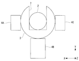
- the piezoelectric elements 4A, 4B, and 4C having the above are illustrated in FIGS. 3A to 6, instead of this, as shown in FIG. 9, the openings of the fitting portions 7 and the optical fiber 2 are opposed to each other in the radial direction.
- the arranged B-phase piezoelectric element 4B may have a thickness dimension that is twice the thickness dimension of the other two A-phase piezoelectric elements 4A and 4C.
- illustration of the holding member 5 and the pressing member 6 is omitted.
- FIG. 9 shows a partially cylindrical elastic member 3 and a fitting portion 7 made of a square groove. The elastic member 3 and the fitting portion 7 having the shapes shown in FIGS. 3B to 5 are employed. Also good.
- the protrusion 2a can be bent and vibrated more stably.
- a stable scanning locus B can be obtained. Furthermore, by making the magnitudes of the alternating voltages of the A phase and the B phase equal, the amplitude of the bending vibration of the protruding portion 2a in the X direction and the Y direction becomes equal. That is, since it is only necessary to supply an alternating voltage having the same magnitude to all the piezoelectric elements 4A, 4B, 4C, the control of the alternating voltage can be facilitated.
- the A-phase piezoelectric elements 4A and 4C and the fitting portion 7 are arranged at substantially equal intervals in the circumferential direction of the optical fiber 2, the A-phase piezoelectric elements 4A and 4C and As shown in FIG. 3A to FIG. 6, the B-phase piezoelectric element 4B has the same thickness dimension, and as the material of the B-phase piezoelectric element 4B, the A-phase piezoelectric elements 4A and 4C A material having a piezoelectric constant d31 that is twice the piezoelectric constant d31 of the material may be employed.
- the piezoelectric constant d31 is a value representing the amount of deformation in the Z direction of the piezoelectric element with respect to the alternating voltage.
- the elastic member 3 and the holding member 5 are formed of separate members, but may be formed of a single member instead. Further, the elastic member 3 may have a longer shape extending toward the proximal end side of the piezoelectric elements 4A, 4B, and 4C, and the holding member 5 may be fixed to the outer peripheral surface of the elastic member 3.
Landscapes
- Physics & Mathematics (AREA)
- Optics & Photonics (AREA)
- Life Sciences & Earth Sciences (AREA)
- General Physics & Mathematics (AREA)
- Health & Medical Sciences (AREA)
- Surgery (AREA)
- Medical Informatics (AREA)
- Molecular Biology (AREA)
- Pathology (AREA)
- Radiology & Medical Imaging (AREA)
- Astronomy & Astrophysics (AREA)
- Engineering & Computer Science (AREA)
- Biomedical Technology (AREA)
- Heart & Thoracic Surgery (AREA)
- Nuclear Medicine, Radiotherapy & Molecular Imaging (AREA)
- Animal Behavior & Ethology (AREA)
- Biophysics (AREA)
- General Health & Medical Sciences (AREA)
- Public Health (AREA)
- Veterinary Medicine (AREA)
- Instruments For Viewing The Inside Of Hollow Bodies (AREA)
- Endoscopes (AREA)
- Mechanical Optical Scanning Systems (AREA)
Abstract
La présente invention concerne un scanner à fibre optique (1) qui est pourvu des éléments suivants : une fibre optique (2) ; un élément élastique (3) qui est fixé à la surface circonférentielle externe de la fibre optique (2) et qui recouvre une partie de direction longitudinale de la fibre optique (2) ; des éléments piézoélectriques (4A, 4B, 4C) qui sont fixés à la surface externe de l'élément élastique (3) ; et une partie d'insertion (7) qui est formée dans l'élément élastique (3) de la surface d'extrémité distale de celui-ci à la surface d'extrémité de base de celui-ci, qui comporte une ouverture sur le côté externe radial de la fibre optique (2), et dans laquelle une partie de direction longitudinale de la fibre optique (2) est disposée.
Priority Applications (2)
| Application Number | Priority Date | Filing Date | Title |
|---|---|---|---|
| PCT/JP2016/062650 WO2017183157A1 (fr) | 2016-04-21 | 2016-04-21 | Scanner à fibre optique, dispositif d'éclairage et dispositif d'observation |
| JP2018512721A JP6710272B2 (ja) | 2016-04-21 | 2016-04-21 | 光ファイバスキャナ、照明装置および観察装置 |
Applications Claiming Priority (1)
| Application Number | Priority Date | Filing Date | Title |
|---|---|---|---|
| PCT/JP2016/062650 WO2017183157A1 (fr) | 2016-04-21 | 2016-04-21 | Scanner à fibre optique, dispositif d'éclairage et dispositif d'observation |
Publications (1)
| Publication Number | Publication Date |
|---|---|
| WO2017183157A1 true WO2017183157A1 (fr) | 2017-10-26 |
Family
ID=60116858
Family Applications (1)
| Application Number | Title | Priority Date | Filing Date |
|---|---|---|---|
| PCT/JP2016/062650 Ceased WO2017183157A1 (fr) | 2016-04-21 | 2016-04-21 | Scanner à fibre optique, dispositif d'éclairage et dispositif d'observation |
Country Status (2)
| Country | Link |
|---|---|
| JP (1) | JP6710272B2 (fr) |
| WO (1) | WO2017183157A1 (fr) |
Citations (4)
| Publication number | Priority date | Publication date | Assignee | Title |
|---|---|---|---|---|
| JPS61106126A (ja) * | 1984-10-31 | 1986-05-24 | オリンパス光学工業株式会社 | 内視鏡装置 |
| JPH03261908A (ja) * | 1990-03-13 | 1991-11-21 | Fujitsu Ltd | 光スイッチ |
| JP2008116922A (ja) * | 2006-09-14 | 2008-05-22 | Optiscan Pty Ltd | 光ファイバ走査装置 |
| WO2015163001A1 (fr) * | 2014-04-22 | 2015-10-29 | オリンパス株式会社 | Dispositif de balayage optique et endoscope de type à balayage |
-
2016
- 2016-04-21 WO PCT/JP2016/062650 patent/WO2017183157A1/fr not_active Ceased
- 2016-04-21 JP JP2018512721A patent/JP6710272B2/ja active Active
Patent Citations (4)
| Publication number | Priority date | Publication date | Assignee | Title |
|---|---|---|---|---|
| JPS61106126A (ja) * | 1984-10-31 | 1986-05-24 | オリンパス光学工業株式会社 | 内視鏡装置 |
| JPH03261908A (ja) * | 1990-03-13 | 1991-11-21 | Fujitsu Ltd | 光スイッチ |
| JP2008116922A (ja) * | 2006-09-14 | 2008-05-22 | Optiscan Pty Ltd | 光ファイバ走査装置 |
| WO2015163001A1 (fr) * | 2014-04-22 | 2015-10-29 | オリンパス株式会社 | Dispositif de balayage optique et endoscope de type à balayage |
Also Published As
| Publication number | Publication date |
|---|---|
| JP6710272B2 (ja) | 2020-06-17 |
| JPWO2017183157A1 (ja) | 2019-02-28 |
Similar Documents
| Publication | Publication Date | Title |
|---|---|---|
| JP6274949B2 (ja) | 光ファイバスキャナ、照明装置および観察装置 | |
| CN105188502B (zh) | 光纤扫描仪、照明装置及观察装置 | |
| JP6129050B2 (ja) | 光ファイバスキャナ、照明装置および観察装置 | |
| JP6498214B2 (ja) | 光ファイバスキャナ、照明装置および観察装置 | |
| JP6345946B2 (ja) | 光ファイバスキャナ、照明装置および観察装置 | |
| CN107072468A (zh) | 光纤扫描器、照明装置以及观察装置 | |
| CN107072466B (zh) | 光纤扫描器、照明装置和观察装置 | |
| JP6518687B2 (ja) | 光走査用アクチュエータ及び光走査装置 | |
| WO2018109883A1 (fr) | Dispositif de balayage à fibre optique, appareil d'éclairage et appareil d'observation | |
| US20180252910A1 (en) | Optical fiber scanner, illumination device, and observation device | |
| JP6865221B2 (ja) | 光ファイバスキャナ、照明装置および観察装置 | |
| JP6710272B2 (ja) | 光ファイバスキャナ、照明装置および観察装置 | |
| JP6553293B2 (ja) | 光ファイバスキャナ、照明装置および観察装置 | |
| WO2016189627A1 (fr) | Dispositif de balayage à fibre optique, dispositif d'éclairage et dispositif d'observation | |
| WO2017068924A1 (fr) | Dispositif de balayage à fibre optique, dispositif d'éclairage et dispositif d'observation | |
| JPWO2018073948A1 (ja) | 光ファイバスキャナ、照明装置および観察装置 | |
| JPWO2017168809A1 (ja) | 光ファイバスキャナ、照明装置および観察装置 | |
| WO2017068651A1 (fr) | Dispositif de balayage à fibre optique, dispositif d'éclairage et dispositif d'observation |
Legal Events
| Date | Code | Title | Description |
|---|---|---|---|
| WWE | Wipo information: entry into national phase |
Ref document number: 2018512721 Country of ref document: JP |
|
| NENP | Non-entry into the national phase |
Ref country code: DE |
|
| 121 | Ep: the epo has been informed by wipo that ep was designated in this application |
Ref document number: 16899429 Country of ref document: EP Kind code of ref document: A1 |
|
| 122 | Ep: pct application non-entry in european phase |
Ref document number: 16899429 Country of ref document: EP Kind code of ref document: A1 |