WO2017183166A1 - Transformateur de noyau de fer enroulé amorphe - Google Patents
Transformateur de noyau de fer enroulé amorphe Download PDFInfo
- Publication number
- WO2017183166A1 WO2017183166A1 PCT/JP2016/062695 JP2016062695W WO2017183166A1 WO 2017183166 A1 WO2017183166 A1 WO 2017183166A1 JP 2016062695 W JP2016062695 W JP 2016062695W WO 2017183166 A1 WO2017183166 A1 WO 2017183166A1
- Authority
- WO
- WIPO (PCT)
- Prior art keywords
- wound core
- iron core
- wound
- amorphous
- insulating paper
- Prior art date
- Legal status (The legal status is an assumption and is not a legal conclusion. Google has not performed a legal analysis and makes no representation as to the accuracy of the status listed.)
- Ceased
Links
Images


Classifications
-
- H—ELECTRICITY
- H01—ELECTRIC ELEMENTS
- H01F—MAGNETS; INDUCTANCES; TRANSFORMERS; SELECTION OF MATERIALS FOR THEIR MAGNETIC PROPERTIES
- H01F27/00—Details of transformers or inductances, in general
- H01F27/24—Magnetic cores
-
- H—ELECTRICITY
- H01—ELECTRIC ELEMENTS
- H01F—MAGNETS; INDUCTANCES; TRANSFORMERS; SELECTION OF MATERIALS FOR THEIR MAGNETIC PROPERTIES
- H01F30/00—Fixed transformers not covered by group H01F19/00
- H01F30/06—Fixed transformers not covered by group H01F19/00 characterised by the structure
- H01F30/10—Single-phase transformers
Definitions
- the present invention relates to a technique for preventing debris scattering of an amorphous wound core transformer made of a foil strip magnetic material.
- transformers are increasingly interested in reducing loss, especially no-load loss (iron loss). ing.
- wound iron cores Most of the amorphous iron cores currently in use are called wound iron cores. Laminate cut foil strips so that the cross-section of the laminate is U-shaped, insert the windings, and then stack the left and right foil strips alternately. By combining them, an iron core that forms a closed magnetic circuit can be produced.
- Patent Document 1 a permanent magnet is disposed so as to cover the laminated surface of the wound core, and fragments generated from the wound core float in the insulating oil to insulate.
- the structure prevents the deterioration from occurring.
- Patent Document 1 As a method for preventing the scattering of broken pieces of the wound iron core, in Patent Document 1, a permanent magnet is disposed so as to cover the laminated surface of the wound iron core to prevent the fragments generated from the wound iron core from floating in the insulating oil and causing insulation deterioration. ing.
- insulating paper or resin is disposed on a part of the laminated end surface of the wound core, and insulating paper is disposed on the wound core wrap portion.
- the present invention is characterized in that a permanent magnet is disposed on a part of the wound core such as a joint between the insulating paper and the resin, a wrap portion of the wound core or an end of the laminated surface. This makes it possible to take measures to prevent debris scattering without deteriorating the magnetic characteristics of the transformer.
- the present application includes a plurality of means for solving the above-described problems.
- a wound iron core, insulating paper, a resin, and a permanent magnet are used, and a resin is disposed on an end surface other than the wrap portion of the wound core.
- the wrap portion is covered with insulating paper, and the permanent magnet is disposed at a location where the insulating paper and the resin are in contact.
- the present invention has been made in view of the above, and by disposing the permanent magnets effectively on the wound iron core, it is possible to take measures to prevent fragment scattering without deteriorating the magnetic characteristics.
- Explanatory drawing of 1 form of the wound iron core transformer of this invention An explanatory view of one form of arrangement and arrangement of permanent magnets proposed in the present invention.
- Explanatory drawing of 1 form of the wound iron core transformer of this invention An explanatory view of one form of arrangement and arrangement of permanent magnets proposed in the present invention.
- An explanatory view of one form of arrangement and arrangement of permanent magnets proposed in the present invention Explanatory drawing of 1 form of the wound iron core transformer of this invention.
- An explanatory view of one form of arrangement and arrangement of permanent magnets proposed in the present invention Explanatory drawing of 1 form of the wound iron core transformer of this invention.
- Explanatory drawing of 1 form of the wound iron core transformer of this invention Explanatory drawing of 1 form of the wound iron core transformer of this invention.
- FIG. 1 is a diagram showing an embodiment of the present invention.
- FIG. 1 is a view of a wound iron core as viewed from the side of the laminated end surface.
- the straight line portion on the upper side of the wound iron core is a wound iron core yoke portion, and the straight line portion on the lower side of the wound iron core is a wound iron core wrap portion.
- the central part of the wound core other than the yoke part and the lap part is the wound core leg part.
- the present invention includes a wound iron core 1, a resin 2 arranged on both sides of a laminated end surface of the wound iron core 1, an insulating paper 3 arranged so as to cover a wrap portion of the wound iron core 1, a winding
- the permanent magnet 4 is roughly constituted by a laminated end face side of the lap portion of the iron core 1 and between the insulating paper 3 and the wound iron core 1.
- the wound core 1 is covered with an insulator such as resin or insulating paper, and an insulator such as a press board or insulating oil is interposed between the legs of the wound core 1 and the winding.
- the wound core 1 is formed by laminating thousands of amorphous foil strips, and an electromagnetic steel sheet having a thickness of about 200 ⁇ m is formed in addition to the entire outermost surface on the side of the wound core foil strip and the innermost lap portion. Has been placed. Therefore, since the debris scattering path of the foil strip is the laminated end face side of the wound core 1 and the lap portion, the configuration of this embodiment blocks the debris scattering path of the foil strip and permanently attracts the amorphous foil strip debris. By effectively arranging the magnets 4, it is possible to strengthen measures for preventing fragment scattering.
- the permanent magnet 4 is, for example, a ferrite magnet, a neodymium magnet, a samarium cobalt magnet, an alnico magnet, or the like, and the thickness is desirably 10 mm or less that does not hinder other structures.
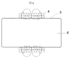
- FIG. 2 illustrates one form of the permanent magnet 4 arranged on the wound core 1.
- FIG. 2 shows a view of the wrap portion of the amorphous wound iron core 1 as viewed from the outer peripheral side of the foil strip surface (the insulating paper 3 is not shown for easy understanding of the magnet arrangement method).
- the magnetic force of the magnet can be changed by the arrangement of the N and S poles of the magnet (communach array).
- a dotted line and an arrow indicate the direction of the magnetic field, and a large arrow indicates a large magnetic field.
- the magnetic force is weaker in the direction from the permanent magnet 4 to the wound core 1 and stronger around the wound core 1. is doing.
- the influence of the permanent magnets 4 on the magnetic properties of the wound core 1 can be reduced, and the foil strip fragments that are to diffuse around the wound core 1 can be attracted more strongly. It is configured.
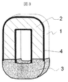
- FIG. 3 is a diagram showing an embodiment of the present invention.
- the arrangement of the permanent magnets 4 is changed with respect to the configuration described in FIG. 1 of the first embodiment, and the permanent magnets 4 are disposed on the outer peripheral portion and the inner peripheral portion of the laminated end surfaces of the yoke portion and the leg portion of the wound core 1.
- the arrangement is arranged.
- the arrangement of the permanent magnets shown in FIG. 3 allows the foil strips to be prevented from scattering even when a gap or a defect occurs between the resin 2 and the wound core laminated end face.
- the permanent magnet 4 is arranged in a Halbach array, so that the influence of the permanent magnet 4 on the magnetic properties of the wound core 1 is reduced, and a piece of foil strip that is to diffuse around the wound core 1. Can be configured to attract more strongly.
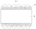
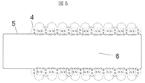
- FIG. 4 shows a view of the yoke portion of the wound core 1 as seen from the outer peripheral side of the foil strip surface. Moreover, the figure seen from the foil strip surface outer peripheral side of the leg part of the wound iron core 1 is shown in FIG. As shown in FIGS. 4 and 5, the magnets are arranged in a Halbach array.
- FIG. 6 is a diagram showing an embodiment of the present invention.
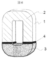
- the present invention has a configuration in which the arrangement of the permanent magnets 4 is changed with respect to the configuration described in FIG. 1 of the first embodiment, and the permanent magnets 4 are arranged at the joint portions of the resin 2 and the insulating paper 3 of the wound core 1.
- the arrangement of the permanent magnets shown in FIG. 6 enables the foil strips to be prevented from scattering even when a gap is generated between the resin 2 and the insulating paper 3.
- FIG. 7 is an enlarged view of the magnet attached to the leg portion of the wound core 1. As shown in FIG. 7, the magnets are arranged in a Halbach array.
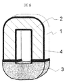
- FIG. 8 is a diagram showing an embodiment of the present invention.
- the arrangement of the permanent magnet 4 is changed with respect to the configuration described in FIG. 1 of the first embodiment, and the outer peripheral portion and inner peripheral portion of the laminated end surface of the yoke portion and the leg portion of the wound core 1 and the wound core 1 are changed.
- the permanent magnet 4 is arranged at the joint between the resin 2 and the insulating paper 3.
- the arrangement of the permanent magnets shown in FIG. 8 allows the foil to be used even when a gap or a defect occurs between the resin 2 and the wound core laminated end face or when a gap occurs between the resin 2 and the insulating paper 3. It is configured to prevent strip debris scattering.
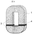
- FIG. 9 is a diagram showing one embodiment of the present invention.
- the present invention covers the entire wound core 1 with the insulating paper 3 without arranging the resin 2 with respect to the configuration described in FIG.
- the configuration is as follows.
Landscapes
- Engineering & Computer Science (AREA)
- Power Engineering (AREA)
- Insulating Of Coils (AREA)
Abstract
La présente invention concerne un transformateur de noyau de fer enroulé amorphe qui peut empêcher la diffusion de débris d'une bande de feuille amorphe sans provoquer de démagnétisation ni d'augmentation de la perte de fer. La présente invention comprend : un noyau de fer enroulé (1); une résine (2) disposée sur les deux côtés des faces d'extrémité de lamination du noyau de fer enroulé (1); du papier isolant (3) disposé de façon à recouvrir une section de rodage du noyau de fer enroulé (1); et un aimant permanent (4) qui est disposé sur un côté de face d'extrémité de lamination de la section de rodage du noyau de fer enroulé (1) et entre le papier isolant (3) et le noyau de fer enroulé (1).
Priority Applications (1)
| Application Number | Priority Date | Filing Date | Title |
|---|---|---|---|
| PCT/JP2016/062695 WO2017183166A1 (fr) | 2016-04-22 | 2016-04-22 | Transformateur de noyau de fer enroulé amorphe |
Applications Claiming Priority (1)
| Application Number | Priority Date | Filing Date | Title |
|---|---|---|---|
| PCT/JP2016/062695 WO2017183166A1 (fr) | 2016-04-22 | 2016-04-22 | Transformateur de noyau de fer enroulé amorphe |
Publications (1)
| Publication Number | Publication Date |
|---|---|
| WO2017183166A1 true WO2017183166A1 (fr) | 2017-10-26 |
Family
ID=60115781
Family Applications (1)
| Application Number | Title | Priority Date | Filing Date |
|---|---|---|---|
| PCT/JP2016/062695 Ceased WO2017183166A1 (fr) | 2016-04-22 | 2016-04-22 | Transformateur de noyau de fer enroulé amorphe |
Country Status (1)
| Country | Link |
|---|---|
| WO (1) | WO2017183166A1 (fr) |
Cited By (1)
| Publication number | Priority date | Publication date | Assignee | Title |
|---|---|---|---|---|
| CN107742569A (zh) * | 2017-11-17 | 2018-02-27 | 山东华驰变压器股份有限公司 | 一种环氧树脂浇筑式非晶合金电抗器铁心及其制备方法 |
Citations (5)
| Publication number | Priority date | Publication date | Assignee | Title |
|---|---|---|---|---|
| JPS6126456U (ja) * | 1984-06-19 | 1986-02-17 | 三菱重工業株式会社 | 切屑回収装置 |
| JPH05217759A (ja) * | 1992-02-07 | 1993-08-27 | Hitachi Ltd | アモルファス巻鉄心変圧器 |
| JPH0582020U (ja) * | 1992-04-06 | 1993-11-05 | 株式会社ダイヘン | アモルファス巻鉄心変圧器 |
| JPH06267773A (ja) * | 1993-03-12 | 1994-09-22 | Takaoka Electric Mfg Co Ltd | 変圧器の製造方法 |
| JPH0831659A (ja) * | 1994-05-13 | 1996-02-02 | Daihen Corp | アモルファス鉄心油入変圧器 |
-
2016
- 2016-04-22 WO PCT/JP2016/062695 patent/WO2017183166A1/fr not_active Ceased
Patent Citations (5)
| Publication number | Priority date | Publication date | Assignee | Title |
|---|---|---|---|---|
| JPS6126456U (ja) * | 1984-06-19 | 1986-02-17 | 三菱重工業株式会社 | 切屑回収装置 |
| JPH05217759A (ja) * | 1992-02-07 | 1993-08-27 | Hitachi Ltd | アモルファス巻鉄心変圧器 |
| JPH0582020U (ja) * | 1992-04-06 | 1993-11-05 | 株式会社ダイヘン | アモルファス巻鉄心変圧器 |
| JPH06267773A (ja) * | 1993-03-12 | 1994-09-22 | Takaoka Electric Mfg Co Ltd | 変圧器の製造方法 |
| JPH0831659A (ja) * | 1994-05-13 | 1996-02-02 | Daihen Corp | アモルファス鉄心油入変圧器 |
Cited By (1)
| Publication number | Priority date | Publication date | Assignee | Title |
|---|---|---|---|---|
| CN107742569A (zh) * | 2017-11-17 | 2018-02-27 | 山东华驰变压器股份有限公司 | 一种环氧树脂浇筑式非晶合金电抗器铁心及其制备方法 |
Similar Documents
| Publication | Publication Date | Title |
|---|---|---|
| JP2018064417A (ja) | 着磁装置 | |
| TWI647719B (zh) | Core for static induction appliances | |
| JPWO2013069076A1 (ja) | 永久磁石埋込型電動機の回転子、及びこの回転子を用いた電動機、及びこの電動機を用いた圧縮機、及びこの圧縮機を用いた空気調和機 | |
| JP5840330B1 (ja) | 静止誘導機器 | |
| JPWO2017085797A1 (ja) | 静止誘導電器の鉄心接合構造及び鉄心接合方法 | |
| JP6075678B2 (ja) | 複合磁心、リアクトルおよび電源装置 | |
| JP7365120B2 (ja) | 静止誘導機器 | |
| JP5900741B2 (ja) | 複合磁心、リアクトルおよび電源装置 | |
| JP6433584B2 (ja) | 点火コイル | |
| JP5404230B2 (ja) | アキシャルギャップ型モータ | |
| US11621115B2 (en) | Method for assembling a magnetic core for a transformer | |
| JP2010109001A (ja) | アモルファス鉄心変圧器 | |
| JP2019125750A (ja) | アモルファス鉄心及び変圧器 | |
| TWI666665B (zh) | 靜態感應器 | |
| JP7149908B2 (ja) | 静止誘導機器 | |
| JP2018113404A (ja) | トランス | |
| JP2007281204A (ja) | 直流リアクトル | |
| JPS5849010B2 (ja) | ギヤツプ付き巻鉄心 | |
| US20230386728A1 (en) | Core for Stationary Electromagnetic Apparatus | |
| JP2011103365A (ja) | リアクトル | |
| JP6890210B2 (ja) | 静止機器 | |
| JP2008258291A (ja) | 内燃機関用点火コイル及びその製造方法 | |
| JP2013062410A (ja) | 変圧器の巻鉄心 | |
| JP2010238874A (ja) | リアクタ | |
| JP2016006813A (ja) | 静止誘導電器 |
Legal Events
| Date | Code | Title | Description |
|---|---|---|---|
| NENP | Non-entry into the national phase |
Ref country code: DE |
|
| 121 | Ep: the epo has been informed by wipo that ep was designated in this application |
Ref document number: 16899438 Country of ref document: EP Kind code of ref document: A1 |
|
| 122 | Ep: pct application non-entry in european phase |
Ref document number: 16899438 Country of ref document: EP Kind code of ref document: A1 |
|
| NENP | Non-entry into the national phase |
Ref country code: JP |