WO2017183175A1 - Tableau de distribution d'alimentation en courant continu - Google Patents
Tableau de distribution d'alimentation en courant continu Download PDFInfo
- Publication number
- WO2017183175A1 WO2017183175A1 PCT/JP2016/062731 JP2016062731W WO2017183175A1 WO 2017183175 A1 WO2017183175 A1 WO 2017183175A1 JP 2016062731 W JP2016062731 W JP 2016062731W WO 2017183175 A1 WO2017183175 A1 WO 2017183175A1
- Authority
- WO
- WIPO (PCT)
- Prior art keywords
- distribution board
- vertical bus
- breakers
- unit base
- phase
- Prior art date
- Legal status (The legal status is an assumption and is not a legal conclusion. Google has not performed a legal analysis and makes no representation as to the accuracy of the status listed.)
- Ceased
Links
Images

Classifications
-
- H—ELECTRICITY
- H02—GENERATION; CONVERSION OR DISTRIBUTION OF ELECTRIC POWER
- H02B—BOARDS, SUBSTATIONS OR SWITCHING ARRANGEMENTS FOR THE SUPPLY OR DISTRIBUTION OF ELECTRIC POWER
- H02B1/00—Frameworks, boards, panels, desks, casings; Details of substations or switching arrangements
- H02B1/26—Casings; Parts thereof or accessories therefor
- H02B1/40—Wall-mounted casings; Parts thereof or accessories therefor
-
- H—ELECTRICITY
- H02—GENERATION; CONVERSION OR DISTRIBUTION OF ELECTRIC POWER
- H02B—BOARDS, SUBSTATIONS OR SWITCHING ARRANGEMENTS FOR THE SUPPLY OR DISTRIBUTION OF ELECTRIC POWER
- H02B1/00—Frameworks, boards, panels, desks, casings; Details of substations or switching arrangements
- H02B1/015—Boards, panels, desks; Parts thereof or accessories therefor
- H02B1/04—Mounting thereon of switches or of other devices in general, the switch or device having, or being without, casing
- H02B1/041—Mechanical coupling for side-by-side mounted apparatus
-
- H—ELECTRICITY
- H02—GENERATION; CONVERSION OR DISTRIBUTION OF ELECTRIC POWER
- H02B—BOARDS, SUBSTATIONS OR SWITCHING ARRANGEMENTS FOR THE SUPPLY OR DISTRIBUTION OF ELECTRIC POWER
- H02B1/00—Frameworks, boards, panels, desks, casings; Details of substations or switching arrangements
- H02B1/015—Boards, panels, desks; Parts thereof or accessories therefor
- H02B1/04—Mounting thereon of switches or of other devices in general, the switch or device having, or being without, casing
- H02B1/056—Mounting on plugboards
-
- H—ELECTRICITY
- H02—GENERATION; CONVERSION OR DISTRIBUTION OF ELECTRIC POWER
- H02J—ELECTRIC POWER NETWORKS; CIRCUIT ARRANGEMENTS OR SYSTEMS FOR SUPPLYING OR DISTRIBUTING ELECTRIC POWER; SYSTEMS FOR STORING ELECTRIC ENERGY
- H02J1/00—Circuit arrangements for DC mains or DC distribution networks
- H02J1/08—Three-wire DC power distribution systems; Systems having more than three wires
-
- H—ELECTRICITY
- H02—GENERATION; CONVERSION OR DISTRIBUTION OF ELECTRIC POWER
- H02B—BOARDS, SUBSTATIONS OR SWITCHING ARRANGEMENTS FOR THE SUPPLY OR DISTRIBUTION OF ELECTRIC POWER
- H02B1/00—Frameworks, boards, panels, desks, casings; Details of substations or switching arrangements
- H02B1/20—Bus-bar or other wiring layouts, e.g. in cubicles, in switchyards
- H02B1/21—Bus-bar arrangements for rack-mounted devices with withdrawable units
-
- H—ELECTRICITY
- H02—GENERATION; CONVERSION OR DISTRIBUTION OF ELECTRIC POWER
- H02B—BOARDS, SUBSTATIONS OR SWITCHING ARRANGEMENTS FOR THE SUPPLY OR DISTRIBUTION OF ELECTRIC POWER
- H02B1/00—Frameworks, boards, panels, desks, casings; Details of substations or switching arrangements
- H02B1/26—Casings; Parts thereof or accessories therefor
- H02B1/40—Wall-mounted casings; Parts thereof or accessories therefor
- H02B1/42—Mounting of devices therein
Definitions
- the present invention relates to a DC power distribution board, and more particularly, to a DC power distribution board having an improved casing structure capable of reducing the number of parts and the number of assembly steps.
- a three-phase four-wire system having four vertical buses is known.
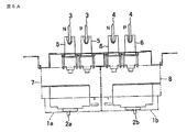
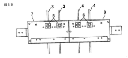
- a structure as shown in FIGS. 5A and 5B is known for direct current power supply. That is, in order to horizontally arrange two units each having two breakers 2a and 2b arranged on the left and right, and to allow the two units to be inserted and removed individually, A total of four vertical buses 3 and 4 are provided. Further, four vertical buses 3 and 4 are arranged in a limited space inside the distribution board, and a flat conductor is employed to secure an insulation distance between the vertical buses 3 and 4.
- the left and right breakers 2a and 2b are respectively provided with protective covers 1a and 1b, and the vertical bus is composed of a vertical bus 3 for the left unit and a vertical bus 4 for the right unit.
- the vertical bus 3 for the left unit is connected to the left contact 5, and the vertical bus 4 for the right unit is connected to the right contact 6.
- the left contact 5 constituting the left unit connected to the vertical bus 3 is mounted on the left unit base 7, and the right contact 6 constituting the right unit connected to the vertical bus 4 is It is mounted on the right unit base 8.
- the conventional DC power distribution board since two units equipped with breakers are arranged horizontally, vertical buses are provided for the left and right units, so four vertical buses are required. For this reason, a space is required in the width direction, and there is a problem that the distribution board for direct current power supply becomes large.
- the conventional control center has a structure in which three Z-shaped vertical buses are arranged in order to supply three-phase AC to each load. The board had insufficient insulation distance, and this structure could not be adopted, and a dedicated design / assembly line had to be secured.
- the present invention can adopt a structure with three vertical buses, and the space of the vertical buses The purpose is to obtain a DC power distribution board that can reduce the size and reduce the cost of materials by unifying parts and reducing assembly man-hours, and further reducing the number of parts. To do.
- the DC power distribution board according to the present invention is a DC power distribution board in which two breakers mounted on a unit base are horizontally arranged, and a central vertical bus for N phase or P phase of a DC circuit is provided. Three vertical buses including the central vertical bus are shared by the two breakers.
- the vertical bus for the N-phase or P-phase of the DC circuit is shared by the two left and right circuit breakers, so that the structure of the three vertical buses can be obtained, and the space of the vertical bus is reduced.
- a distribution board for direct current power supply that can be miniaturized.
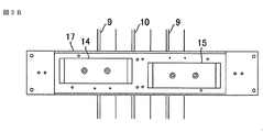
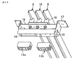
- FIG. 1A It is a top view which shows the state which mounted the unit of the electricity distribution panel by Embodiment 1 of this invention. It is a front view which shows the state which removed the breaker from FIG. 1A. It is a perspective view which shows the state which mounted the unit of the electricity distribution panel by Embodiment 1 of this invention. It is a top view which shows the state which mounted the unit of the electricity distribution panel by Embodiment 2 of this invention. It is a front view which shows the state which removed the breaker from FIG. 3A. It is a perspective view which shows the state in which the unit of the electricity distribution panel by Embodiment 2 of this invention was mounted, and the breaker was inserted in the terminal block. It is a perspective view which shows the state by which the breaker of FIG.
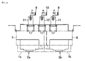
- FIG. 1A is a plan view showing a state in which a unit is mounted on a DC power distribution board according to Embodiment 1 of the present invention
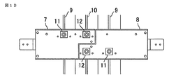
- FIG. 1B is a front view showing a state in which a breaker is removed from FIG. 1A.
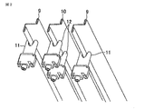
- FIG. 2 is a perspective view showing only necessary members so that the position where the contact 12 is engaged with the central vertical bus 10 can be seen.
- the vertical bus 10 has a structure of three vertical buses, and the vertical bus 10 for the N phase (or P phase) of the DC circuit is arranged in the center.
- the remaining vertical buses 9 for the P phase (or N phase) are arranged on both sides of the vertical bus 10 arranged in the center.
- the left and right breakers 2a and 2b are respectively provided with protective covers 1a and 1b, and the contact 12 connected to the central vertical bus 10 is a unit on the left side as seen in FIG. 1B.
- a portion of the base 7 and the right unit base 8 is cut away, and the end portions with a narrow width are arranged side by side in a vertical direction.
- the contacts 11 connected to the left and right vertical buses 9 are provided on the left unit base 7 and the right unit base 8, respectively.
- the unit base is a member that serves as a base for fixing each member of the unit.
- the front view shown in FIG. 1B is a diagram showing only necessary members by removing the breakers 2a and 2b so that the shapes of the left unit base 7 and the right unit base 8 can be understood.
- the left unit base 7 has a shape in which the lower right portion is cut out when viewed from the front
- the right unit base 8 has a shape in which the upper left portion is cut out when viewed from the front.
- the distribution board center sides of the left unit base 7 and the right unit base 8 are arranged in a stepped manner. This shape makes it possible to arrange the central portions of the units in steps.
- the contact 12 connected to the central vertical bus 10 is arranged in the vertical direction in the portion where the width is narrowed by notching the end.
- a contact 12 that engages with the N-phase (or P-phase) vertical bus 10 is provided on each of the left-side unit base 7 and the right-side unit base 8 that are arranged in steps.
- the contact 11 that engages with the remaining P-phase (or N-phase) vertical bus 9 is on the left side of the contact 12 in the case of the left unit base 7 and on the right side of the unit base 8.
- FIG. 2 The perspective view of FIG. 2 is a diagram showing only necessary members so that the contact position of the contact 12 to the central vertical bus 10 can be understood.
- the left and right unit bases 7 and 7 are provided on the left and right unit bases 7 and 8 by providing the contact 12 connected to the central vertical bus 10 in the unit base portions arranged in steps. Are arranged in the horizontal direction, and the central vertical bus 10 can be shared.
- the DC power distribution board according to Embodiment 1 has a structure in which the left and right breakers 2a and 2b mounted on the unit bases 7 and 8 are horizontally arranged, respectively.
- the central vertical bus 10 for the N phase (or P phase) of the DC circuit is shared by the two left and right breakers 2a and 2b mounted on the unit bases 7 and 8, respectively.
- Three structures can be adopted. Further, three vertical buses including the central vertical bus 10 and the vertical buses 9 and 9 arranged on both sides of the central vertical bus 10 are configured, and the vertical bus 10 for the N phase (or P phase) of the DC circuit is provided.
- the vertical bus structure adopted in the control center can be applied, it is possible to unify parts and reduce assembly man-hours, and to reduce material costs by reducing the number of parts.
- the DC power distribution board includes a unit having a unit base 7 on which a breaker 2a is mounted and a unit having a unit base 8 on which a breaker 2b is mounted.
- the center side of each distribution board is formed in a shape that extends in a vertical plane and is arranged in a stepwise manner, and the contact 12 connected to the central vertical bus 10 is arranged in the stepped portion, thereby Since the left and right units are arranged horizontally while the central vertical bus 10 is shared by the left and right units, the vertical bus for the N phase (or P phase) of the DC circuit is shared by the left and right breakers.
- the structure of three vertical buses can be provided, and the space for the vertical buses can be reduced, and a DC power distribution board that can be miniaturized can be obtained.
- the contactor 12 for connecting to the breakers 2a and 2b connected to the central vertical bus 10 is arranged at the stepped portions of 7 and 8 and the left and right unit bases 7 and 8 are complementarily combined to reduce the size. Can do.
- the DC power distribution board includes a unit having a unit base 7 on which a breaker 2a is mounted and a unit having a unit base 8 on which a breaker 2b is mounted.
- Each center end has a shape in which one end of the two left and right units is cut out in the lower half, and the other end is cut out in the upper half. Since the left and right units are arranged horizontally by matching, the vertical buses for the N phase (or P phase) of the DC circuit are shared by the left and right breakers, so that three vertical buses are provided. Thus, it is possible to obtain a DC power distribution board that can reduce the space of the vertical bus bar and can be miniaturized.
- the vertical bus structure adopted in the control center can be applied, it is possible to unify parts and reduce assembly man-hours, and further reduce material costs by reducing the number of parts. It is possible to reduce the size by combining the left and right units having a shape in which the upper half or the lower half of the two are cut and combined in a complementary manner.
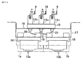
- FIG. 4A is a plan view showing a state in which a distribution board unit according to Embodiment 2 is mounted
- FIG. 3B is a front view showing a state in which a breaker is removed from FIG. 3A
- 4A is a perspective view showing a state in which a distribution board unit is mounted and the breaker is inserted into the terminal block
- FIG. 4B is a perspective view showing a state in which the breaker in FIG. 4A is pulled out from the terminal block. .
- the insertion terminal block 14 in order to connect the insertion breakers 13a and 13b, is provided on the left side when viewed from the front of the unit base 17, and the insertion terminal block 15 is provided on the right side.
- a cable 19 for the N phase (or P phase) of the DC circuit from a middle phase contact portion of the contact 16 attached to the contact fixing plate 18, that is, a contact portion of the contact 16 connected to the central vertical bus 10. Are wired to the primary terminal of the insertion terminal block 14 and the insertion terminal block 15.
- the cable 20 is transferred from the left phase (left phase contact portion) of the contact 16 to the primary terminal of the left insertion terminal block 14, and the right phase (right The cable 21 is wired from the phase contact portion) to the primary terminal of the right insertion terminal block 15.
- the insertion / removal of the insertion breakers 13a and 13b can be made independent with the configuration of three vertical buses.
- FIG. 4A is a view showing a state in which the insertion breaker 13a is connected to the left insertion terminal block 14 and the insertion breaker 13b is connected to the right insertion terminal block 15.
- FIG. 4B is a diagram illustrating a state in which the plug-in type breaker 13a is pulled out from the plug terminal block 14 on the left side and the plug-in type breaker 13b is pulled out from the plug terminal block 15 on the right side.
- the second embodiment is a DC power distribution board having a structure in which two left and right plug-in type breakers 13a and 13b mounted on the same unit base 17 are arranged in series in a horizontal state.
- the central vertical bus 10 for (or P phase) is shared by the two left and right plug-in type breakers 13a and 13b mounted on the unit base 17, and is arranged on both sides of the central vertical bus 10 and the central vertical bus 10.
- Three vertical buses including the vertical buses 9 and 9 are configured, the unit base 17 is common to the two left and right plug-in type breakers 13a and 13b, and the plug-in type breakers 13a and 13b are connected to the common unit base 17. Two units are arranged side by side in series in the horizontal direction.
- the unit base 17 is provided with an intermediate phase contact portion 16a connected to the central vertical bus 10, a left phase contact portion 16b connected to the left P-phase (or N-phase) vertical bus 9, and a right P From the contact 16 having the right phase contact portion 16c connected to the phase (or N phase) vertical bus 9, the intermediate phase contact portion 16a is provided by the cable 19 to the insertion breaker 13a and the insertion breaker 13b, respectively.
- the central vertical bus 10 is connected to the two left and right sides. Since the break-in type breakers 13a and 13b are shared, it is possible to obtain a DC power distribution board that can have three vertical buses, reduce the space of the vertical buses, and can be downsized. Can do.
- the vertical bus structure adopted in the control center can be applied, it is possible to unify parts and reduce assembly man-hours, further reduce material costs by reducing the number of parts, and vertical bus bars.
- independence of the insertion / removal of the insertion-type breakers 13a and 13b can be ensured with the three configurations.
- the insertion terminal block 14 connected to the insertion breaker 13a and the insertion terminal block 15 connected to the insertion breaker 13b are arranged in series on a common unit base 17 and arranged in the horizontal direction.
- an N-phase (or P-phase) cable 19 of the DC circuit is inserted from the middle-phase contact portion 16a of the contact 16 provided on the unit base 17 and connected to the central vertical bus 10 to the plug-in terminal block 14 and plug-in.
- One of the two primary terminals provided on each of the terminals 15 is wired and connected to one of the primary terminals of the plug-in type breakers 13a and 13b.
- the remaining P-phase (or N-phase) is wired with the cable 20 from the left-phase contact portion 16b of the contact 16 to the other primary side terminal of the insertion terminal block 14 to the primary side terminal of the insertion type breaker 13a.
- the central vertical bus 10 is connected by connecting the right-phase contact portion 6c of the contact 16 to the other primary side terminal of the insertion terminal block 15 with the cable 21 and connecting to the other primary side terminal of the insertion breaker 13b.
- the vertical bus structure adopted in the control center can be applied, it is possible to unify parts and reduce assembly man-hours, further reduce material costs by reducing the number of parts, and vertical bus bars.
- independence of the insertion / removal of the insertion-type breakers 13a and 13b can be ensured with the three configurations.
- each embodiment can be freely combined, or each embodiment can be appropriately modified or omitted.
Landscapes
- Engineering & Computer Science (AREA)
- Power Engineering (AREA)
- Distribution Board (AREA)
- Patch Boards (AREA)
Abstract
L'invention porte sur un tableau de distribution d'alimentation en courant continu qui possède une structure telle que : les côtés centraux de bases d'unité droite et gauche (7, 8) du tableau de distribution sur lesquelles des disjoncteurs (2) sont montés sont formés de manière à pouvoir être disposés dans un agencement étagé ; et des unités peuvent être disposées horizontalement tout en partageant une ligne de bus verticale centrale (10). Dans une autre structure, deux disjoncteurs du type à insertion (13) sont disposés dans une direction horizontale sur la même base d'unité (17) et un câblage menant à la borne côté primaire de chacun des disjoncteurs est réalisé à partir d'un contacteur (16) disposé sur la base d'unité (17), partageant ainsi la ligne de bus verticale centrale (10) avec les disjoncteurs droit et gauche (13).
Priority Applications (2)
| Application Number | Priority Date | Filing Date | Title |
|---|---|---|---|
| US16/073,231 US10439373B2 (en) | 2016-04-22 | 2016-04-22 | DC power supply distribution board |
| PCT/JP2016/062731 WO2017183175A1 (fr) | 2016-04-22 | 2016-04-22 | Tableau de distribution d'alimentation en courant continu |
Applications Claiming Priority (1)
| Application Number | Priority Date | Filing Date | Title |
|---|---|---|---|
| PCT/JP2016/062731 WO2017183175A1 (fr) | 2016-04-22 | 2016-04-22 | Tableau de distribution d'alimentation en courant continu |
Publications (1)
| Publication Number | Publication Date |
|---|---|
| WO2017183175A1 true WO2017183175A1 (fr) | 2017-10-26 |
Family
ID=60116652
Family Applications (1)
| Application Number | Title | Priority Date | Filing Date |
|---|---|---|---|
| PCT/JP2016/062731 Ceased WO2017183175A1 (fr) | 2016-04-22 | 2016-04-22 | Tableau de distribution d'alimentation en courant continu |
Country Status (2)
| Country | Link |
|---|---|
| US (1) | US10439373B2 (fr) |
| WO (1) | WO2017183175A1 (fr) |
Families Citing this family (2)
| Publication number | Priority date | Publication date | Assignee | Title |
|---|---|---|---|---|
| US11018479B2 (en) * | 2016-04-11 | 2021-05-25 | Mitsubishi Electric Corporation | Distribution board |
| US11799272B2 (en) | 2019-12-13 | 2023-10-24 | Eaton Intelligent Power Limited | Dual contactor electrical panelboard assembly, systems and methods |
Citations (6)
| Publication number | Priority date | Publication date | Assignee | Title |
|---|---|---|---|---|
| JPS60128806A (ja) * | 1983-12-14 | 1985-07-09 | 株式会社日立製作所 | 高集積制御盤 |
| JPH0711742U (ja) * | 1993-07-21 | 1995-02-21 | 日東工業株式会社 | 回路遮断器 |
| JP2004282802A (ja) * | 2003-03-12 | 2004-10-07 | Nitto Electric Works Ltd | 分電盤 |
| JP2009178030A (ja) * | 2007-12-25 | 2009-08-06 | Panasonic Electric Works Co Ltd | 直流配電システム |
| JP2012065465A (ja) * | 2010-09-16 | 2012-03-29 | Nitto Kogyo Co Ltd | プラグイン分電盤 |
| WO2015029474A1 (fr) * | 2013-08-26 | 2015-03-05 | 三菱電機株式会社 | Appareil à unités |
Family Cites Families (6)
| Publication number | Priority date | Publication date | Assignee | Title |
|---|---|---|---|---|
| US3142002A (en) * | 1962-08-24 | 1964-07-21 | Gen Electric | Circuit breaker panel assembly with discriminating means |
| JPS6329310U (fr) | 1986-08-04 | 1988-02-26 | ||
| US5322982A (en) * | 1992-05-05 | 1994-06-21 | Square D Company | Fusible switch |
| US5978209A (en) * | 1998-08-14 | 1999-11-02 | General Electric Company | Lock-down device for a circuit breaker assembly and assembly incorporating same |
| US6472605B1 (en) * | 2000-04-13 | 2002-10-29 | Larry D. Griffith | Frangible work cover for breaker box |
| US8482905B2 (en) * | 2011-07-13 | 2013-07-09 | General Electric Company | Mounting modules for a DC distribution assembly |
-
2016
- 2016-04-22 WO PCT/JP2016/062731 patent/WO2017183175A1/fr not_active Ceased
- 2016-04-22 US US16/073,231 patent/US10439373B2/en active Active
Patent Citations (6)
| Publication number | Priority date | Publication date | Assignee | Title |
|---|---|---|---|---|
| JPS60128806A (ja) * | 1983-12-14 | 1985-07-09 | 株式会社日立製作所 | 高集積制御盤 |
| JPH0711742U (ja) * | 1993-07-21 | 1995-02-21 | 日東工業株式会社 | 回路遮断器 |
| JP2004282802A (ja) * | 2003-03-12 | 2004-10-07 | Nitto Electric Works Ltd | 分電盤 |
| JP2009178030A (ja) * | 2007-12-25 | 2009-08-06 | Panasonic Electric Works Co Ltd | 直流配電システム |
| JP2012065465A (ja) * | 2010-09-16 | 2012-03-29 | Nitto Kogyo Co Ltd | プラグイン分電盤 |
| WO2015029474A1 (fr) * | 2013-08-26 | 2015-03-05 | 三菱電機株式会社 | Appareil à unités |
Also Published As
| Publication number | Publication date |
|---|---|
| US10439373B2 (en) | 2019-10-08 |
| US20190044311A1 (en) | 2019-02-07 |
Similar Documents
| Publication | Publication Date | Title |
|---|---|---|
| JP2015095459A (ja) | 配線用遮断器 | |
| KR20040002676A (ko) | 전자기적 보호 및 제어 어셈블리 | |
| JP4250058B2 (ja) | ジャンクションブロックの回路構造 | |
| KR100973944B1 (ko) | 분전반용 플러그 | |
| EP2400610B1 (fr) | Barres support et module de distribution électrique comprenant lesdites barres | |
| CN106877186A (zh) | 固定的竖直配电母线 | |
| WO2017183175A1 (fr) | Tableau de distribution d'alimentation en courant continu | |
| JP6173579B2 (ja) | 母線構造およびこれを用いた配電盤 | |
| CN205356162U (zh) | 在两个母线之间带有至少一个逆变器桥的逆变器 | |
| JP6270618B2 (ja) | 接続導体ユニット | |
| JP2010029018A (ja) | 閉鎖配電盤 | |
| KR101584296B1 (ko) | 배전반 | |
| JP6057977B2 (ja) | 直流給電用分電盤 | |
| JP3113266U (ja) | ユニット式分電盤 | |
| JP2020137133A (ja) | 切替開閉器 | |
| KR101615602B1 (ko) | 배전반 버킷의 2차측 커넥터 | |
| JP6169061B2 (ja) | 分電盤 | |
| JP6433336B2 (ja) | 分電盤 | |
| JP4722677B2 (ja) | 配電盤 | |
| JP2006149118A (ja) | 低圧配電用しゃ断装置 | |
| KR101610811B1 (ko) | 상전환용 부스덕트 | |
| JP2017224444A (ja) | 切替開閉器 | |
| JP4177304B2 (ja) | 電気接続箱の端子台接続構造 | |
| WO2017179092A1 (fr) | Tableau de distribution | |
| JP2005204464A (ja) | 配電盤 |
Legal Events
| Date | Code | Title | Description |
|---|---|---|---|
| NENP | Non-entry into the national phase |
Ref country code: DE |
|
| 121 | Ep: the epo has been informed by wipo that ep was designated in this application |
Ref document number: 16899447 Country of ref document: EP Kind code of ref document: A1 |
|
| 122 | Ep: pct application non-entry in european phase |
Ref document number: 16899447 Country of ref document: EP Kind code of ref document: A1 |
|
| NENP | Non-entry into the national phase |
Ref country code: JP |