WO2017183204A1 - 動画像符号化装置および動画像符号化方法 - Google Patents
動画像符号化装置および動画像符号化方法 Download PDFInfo
- Publication number
- WO2017183204A1 WO2017183204A1 PCT/JP2016/062845 JP2016062845W WO2017183204A1 WO 2017183204 A1 WO2017183204 A1 WO 2017183204A1 JP 2016062845 W JP2016062845 W JP 2016062845W WO 2017183204 A1 WO2017183204 A1 WO 2017183204A1
- Authority
- WO
- WIPO (PCT)
- Prior art keywords
- moving image
- area
- intra refresh
- intra
- unit
- Prior art date
- Legal status (The legal status is an assumption and is not a legal conclusion. Google has not performed a legal analysis and makes no representation as to the accuracy of the status listed.)
- Ceased
Links
Images


Classifications
-
- H—ELECTRICITY
- H04—ELECTRIC COMMUNICATION TECHNIQUE
- H04N—PICTORIAL COMMUNICATION, e.g. TELEVISION
- H04N19/00—Methods or arrangements for coding, decoding, compressing or decompressing digital video signals
- H04N19/10—Methods or arrangements for coding, decoding, compressing or decompressing digital video signals using adaptive coding
- H04N19/102—Methods or arrangements for coding, decoding, compressing or decompressing digital video signals using adaptive coding characterised by the element, parameter or selection affected or controlled by the adaptive coding
- H04N19/103—Selection of coding mode or of prediction mode
- H04N19/107—Selection of coding mode or of prediction mode between spatial and temporal predictive coding, e.g. picture refresh
-
- H—ELECTRICITY
- H04—ELECTRIC COMMUNICATION TECHNIQUE
- H04N—PICTORIAL COMMUNICATION, e.g. TELEVISION
- H04N19/00—Methods or arrangements for coding, decoding, compressing or decompressing digital video signals
- H04N19/10—Methods or arrangements for coding, decoding, compressing or decompressing digital video signals using adaptive coding
- H04N19/134—Methods or arrangements for coding, decoding, compressing or decompressing digital video signals using adaptive coding characterised by the element, parameter or criterion affecting or controlling the adaptive coding
- H04N19/167—Position within a video image, e.g. region of interest [ROI]
-
- H—ELECTRICITY
- H04—ELECTRIC COMMUNICATION TECHNIQUE
- H04N—PICTORIAL COMMUNICATION, e.g. TELEVISION
- H04N19/00—Methods or arrangements for coding, decoding, compressing or decompressing digital video signals
- H04N19/10—Methods or arrangements for coding, decoding, compressing or decompressing digital video signals using adaptive coding
- H04N19/169—Methods or arrangements for coding, decoding, compressing or decompressing digital video signals using adaptive coding characterised by the coding unit, i.e. the structural portion or semantic portion of the video signal being the object or the subject of the adaptive coding
- H04N19/17—Methods or arrangements for coding, decoding, compressing or decompressing digital video signals using adaptive coding characterised by the coding unit, i.e. the structural portion or semantic portion of the video signal being the object or the subject of the adaptive coding the unit being an image region, e.g. an object
- H04N19/172—Methods or arrangements for coding, decoding, compressing or decompressing digital video signals using adaptive coding characterised by the coding unit, i.e. the structural portion or semantic portion of the video signal being the object or the subject of the adaptive coding the unit being an image region, e.g. an object the region being a picture, frame or field
Definitions
- the present invention relates to a moving image encoding apparatus and a moving image encoding method.
- Patent Document 1 describes that economical video communication is realized by obtaining a region of interest in received video with high definition.
- Patent Document 1 has no description on how to perform intra refresh.
- an object of the present invention is to provide a technique capable of further reducing the code amount of moving image data.
- a moving picture encoding apparatus includes an intra unit that performs intra refresh on a moving picture, and an intra refresh area smaller than a frame for each picture in a gaze area on the moving picture. And a control unit that controls to perform the intra refresh in the intra refresh area.
- the code amount of moving image data can be further reduced. Problems, configurations, and effects other than those described above will be clarified by the following description of embodiments.
- FIG. 3 is a flowchart illustrating an operation example of the moving image transmission system 1.
- 5 is a flowchart illustrating an operation example of the moving image encoding device 22. It is a figure explaining the example of a change of the magnitude
- FIG. 1 is a diagram showing an example of a moving picture transmission system 1 using a moving picture coding apparatus according to the present invention.
- the moving image transmission system 1 includes an information processing device 11, a gaze area detection device 12, an imaging camera 21, a moving image encoding device 22, an operation device 31, and an operation object 32. have.
- the information processing apparatus 11 communicates with the moving image encoding apparatus 22 and the operation apparatus 31 via, for example, the network 41 that is the Internet.
- the information processing apparatus 11 is a personal computer, for example.
- the information processing apparatus 11 includes a display device 11a and an input device 11b.
- An operator who operates the information processing device 11 operates the input device 11b such as a joystick or a mouse while viewing the operation device 31 and the operation target object 32 displayed on the display device 11a of the information processing device 11 to operate the operation device. 31 is operated remotely.
- the operating device 31 is, for example, a robot.
- the operation device 31 operates in accordance with an instruction from the information processing device 11 and performs a predetermined operation on the operation object 32.
- the gaze area detection device 12 detects which part of the image displayed by the operator is displayed on the display device 11a.
- an area of the image viewed by the operator may be referred to as a gaze area.
- the information processing apparatus 11 transmits the data of the gaze area detected by the gaze area detection apparatus 12 to the moving image encoding apparatus 22 via the network 41.
- the data of the gaze area transmitted by the information processing apparatus 11 may be simply referred to as a gaze area.
- the moving image encoding device 22 encodes the image data captured by the imaging camera 21 and transmits the encoded image data to the information processing device 11 via the network 41.
- the operator does not gaze at the entire area of the moving image captured by the imaging camera 21 but gazes at part of the operation device 31 or the operation target object 32. Therefore, the moving image encoding device 22 performs intra refresh in the gaze area of the operator detected by the gaze area detection device 12 when encoding the image data.
- the moving image encoding device 22 does not perform the intra refresh on the entire area of the image data captured by the imaging camera 21, but performs the intra refresh on the image area (gaze area) that the operator is viewing. .
- the moving image encoding device 22 can reduce the code amount of the moving image data while suppressing the deterioration of the image quality of the gaze area of the operator.
- the moving image encoding device 22 can transmit moving image data to the information processing device 11 at a low rate while suppressing deterioration in image quality of the operator's gaze area.
- the system to which the moving image encoding device 22 is applied is not limited to the example of FIG. 1, and the system to which the moving image encoding device 22 is applied can be applied to a system other than a remote operation such as a robot.
- a system other than a remote operation such as a robot.
- the gaze area of the supervisor may be detected and the area for intra refresh may be determined.
- the information processing apparatus 11 transmits the gaze area detected by the gaze area detection apparatus 12 to the moving image encoding apparatus 22, but the gaze area detection apparatus 12 does not pass through the information processing apparatus 11.
- the detected gaze area may be transmitted to the moving image encoding device 22.
- the operation device 31 may include the imaging camera 21 and the moving image encoding device 22.
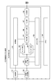
- FIG. 2 is a diagram showing an example of functional blocks of the moving picture encoding device 22 of FIG.
- the moving image encoding device 22 includes a receiving unit 51, an image processing unit 52, an encoding unit 53, and a memory 54.
- the receiving unit 51 receives an operator's gaze area from the information processing apparatus 11 via the network 41.
- the receiving unit 51 outputs the gaze area received from the information processing apparatus 11 to the control unit 61 and the image processing unit 52.
- the image data of the moving image captured by the imaging camera 21 is input to the image processing unit 52.
- the image processing unit 52 Based on the gaze area received by the receiving unit 51, the image processing unit 52 performs a filtering process on the area outside the gaze area of the image data (blurs the image data outside the gaze area).
- the frame of the gaze area received by the receiving unit 51 is indicated by coordinates on the moving image, and the image processing unit 52 performs filter processing on image data outside the frame indicated by the coordinates.
- the image processing unit 52 performs filter processing for each predetermined line when performing filter processing of image data. For example, the image processing unit 52 inputs the image data output from the imaging camera 21 in the raster scan order, holds a plurality of lines of the input image data, and performs a filtering process outside the gaze area. The image processing unit 52 outputs the image data that has been input and filtered by predetermined lines to the encoding unit 53.
- the encoding unit 53 temporarily holds the image data output from the image processing unit 52 in the memory I / F unit 69, reads out the image data in MB (Macro Block) units, and performs moving image encoding. , Output stream information.
- the encoding unit 53 includes a control unit 61, an image input unit 62, an intra unit 63, an inter unit 64, a determination unit 65, a DCT / Q (DiscreteQCosine Transform / quantization) unit 66, and a VLC (Variable Length).
- a coding unit 67, a transmission unit 68, and a memory interface (I / F) unit 69 is a control unit 61, an image input unit 62, an intra unit 63, an inter unit 64, a determination unit 65, a DCT / Q (DiscreteQCosine Transform / quantization) unit 66, and a VLC (Variable Length).
- the gaze area received by the receiving unit 51 is input to the control unit 61.
- the control unit 61 controls the determination unit 65 so that intra refresh is performed in the gaze area of the image data.
- the gaze area received by the receiving unit 51 is indicated by coordinates on the moving image.
- the control unit 61 determines an MB in the gaze area based on the coordinates of the gaze area, and controls the determination unit 65 so that intra refresh is performed in the MB.
- the image input unit 62 stores the filtered image data output from the image processing unit 52 in the memory 54 line by line via the memory I / F unit 69.
- the image input unit 62 stores the image data output from the image processing unit 52 in the memory 54 for each MB line.
- the intra unit 63 reads out image data for a predetermined line stored in the memory 54 via the memory I / F unit 69, and performs an intra prediction process.
- the inter unit 64 reads out image data for a predetermined line stored in the memory 54 via the memory I / F unit 69 and performs inter prediction processing.
- the determination unit 65 determines whether to use intra prediction of the intra unit 63 or inter prediction of the inter unit 64. For example, the determination unit 65 determines the intra prediction of the intra unit 63 and the inter unit based on the information amount of the image data when the intra prediction is performed, the information amount of the image data when the inter prediction is performed, and other parameters. It is determined which of 64 inter prediction is adopted. The determination unit 65 outputs the adopted prediction to the DCT / Q unit 66.
- control unit 61 controls the determination unit 65 so that intra refresh is adopted in the gaze area of the image data.
- the DCT / Q unit 66 DCT-transforms the prediction error determined by the determination unit 65 and quantizes the prediction error.
- the VLC unit 67 encodes the image information quantized by the DCT / Q unit 66 and the information on the encoding mode determined by the determination unit 65.
- the transmission unit 68 transmits the image data encoded by the VLC unit 67 to the information processing apparatus 11 via the network 41.
- the memory I / F unit 69 writes image data, decoded images, streams, and the like for each predetermined line output from the image input unit 62 in the memory 54.
- the memory I / F unit 69 reads image data on which the intra prediction process is executed and image data on which the inter prediction process is executed from the memory 54.
- the memory 54 is a memory for temporarily storing image data.
- the moving image encoding device 22 shown in FIG. 2 reduces the image information of the other areas with a high image quality in the operator's gaze area for the purpose of reducing the amount of codes. Thereby, the moving image encoding device 22 realizes low-rate encoding while keeping the image quality of the gaze area.
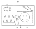
- FIG. 3 is a diagram for explaining a schematic operation example of the video encoding device 22 of FIG.
- FIG. 3 shows an image 81 displayed on the display device 11 a of the information processing apparatus 11. That is, the image 81 is an image captured by the imaging camera 21.
- FIG. 3 shows an example in which the controller device 31 and the operation target 32 are imaged.
- a dotted line frame 82 shown in the image 81 indicates the gaze area of the operator detected by the gaze area detection device 12.
- the image processing unit 52 of the moving image encoding device 22 performs, for example, a low-pass filter on an area outside the gaze area indicated by the dotted frame 82. That is, the image processing unit 52 performs a process of blurring an image (a process of reducing the information amount of the image) in an area outside the gaze area, and reduces the information amount of the image data transmitted to the information processing apparatus 11.
- control unit 61 of the moving image encoding device 22 performs control so that intra refresh is executed in the gaze area indicated by the dotted frame 82. That is, the control unit 61 performs control so that intra refresh is performed not in the entire moving image area but in the operator's gaze area, thereby reducing the code amount of the moving image data. Then, the control unit 61 reduces the moving image data to be transmitted to the information processing apparatus 11.
- the image processing unit 52 performs a filtering process on the image data for each predetermined line without storing all data of one image in a memory (not shown).
- the encoding unit 53 performs an encoding process on the image data for each predetermined line without storing all the data of one image in the memory.
- the moving image encoding device 22 is configured to store the predetermined lines in the memory and execute the process immediately after the storage. Thereby, the moving image encoding device 22 can reduce the delay of transmission of moving image data to the information processing device 11. Further, by reducing the delay of the moving image data, the operator can operate the operation device 31 in real time, and the operability of the operation device 31 is improved.
- region shown by a dotted-line frame is made into the rectangle, the ellipse similar to a human eye and circular may be sufficient.
- the area outside the gaze area may be adjusted according to the distance from the gaze area, such as increasing the intensity of blurring the image. Thereby, the moving image encoding device 22 can perform the original image processing process with lower delay.
- FIG. 4 is a diagram for explaining an example of the encoding process.
- FIG. 4 shows the encoding type of the input frame with the arrow direction as the time axis.
- an encoding type referred to only a past frame called a P picture is continuously used for an input image (the first frame is a screen image).
- an intra MB to be encoded as a still image is equally arranged in a band (intra refresh) in each picture with respect to a rectangular processing unit (MB) in an image.
- MB rectangular processing unit
- FIG. 5 is a diagram illustrating an example of intra refresh.
- FIG. 5 shows the encoding type of the input frame with the arrow direction as the time axis. Also, the black band shown in FIG. 5 indicates an area (intra MB) to be intra-refreshed.
- an intra MB black band shown in FIG. 5
- an intra MB black band shown in FIG. 5
- the rate of moving image data can be made uniform.
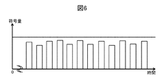
- FIG. 6 is a diagram for explaining a rate example of moving image data by encoding processing.
- the vertical axis shown in FIG. 6 indicates the amount of moving image data encoded by the encoding process, and the horizontal axis indicates time.
- the intra refresh it is possible to encode the code amount for each unit (for example, one frame) so as to be within a predetermined transfer rate (dotted line shown in FIG. 6).
- the rate can be made uniform (the rate can be kept from fluctuating greatly).
- the intra refresh area is arranged without considering the important area in the moving image. Therefore, in the encoding processing described in FIGS. 4, 5, and 6, intra coding is performed even on an unimportant region that is not watched by the operator, and the amount of code is consumed wastefully. . On the other hand, in the moving image encoding device 22, intra refresh is performed in the gaze area where the operator gazes.
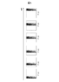
- FIG. 7 is a diagram for explaining intra-refresh by the moving picture encoding device 22.
- FIG. 7 shows the encoding type of the input frame with the arrow direction as the time axis.
- zone shown in FIG. 7 has shown the area
- the dotted frame shown in FIG. 7 has shown the gaze area
- the control unit 61 of the moving picture encoding device 22 shown in FIG. 2 performs the following in the gaze area of the dotted frame shown in each P picture (P-pic shown in FIG. 7) based on the gaze area received by the reception unit 51.
- An intra refresh area black band shown in FIG. 7) is arranged so as to cover the area.
- control unit 61 moves the band-like intra refresh area whose vertical and horizontal directions are smaller than the frame for each P picture so as to cover the entire gaze area, and intra refresh is executed in the intra refresh area.
- the determination unit 65 is controlled as described above.
- the intra refresh area is desirably larger than the search range in the inter prediction.
- the intra refresh area is moved from left to right, but may be moved from right to left. Also, the intra refresh area may be moved from top to bottom or from bottom to top.
- the vertical direction or horizontal direction of the gaze area may be larger than the vertical direction or horizontal direction of the band-like intra refresh area.
- the vertical direction of the dotted frame shown in FIG. 7 may be larger than the vertical direction of the black band.
- the control unit 61 scans the intra refresh area so that the intra refresh area covers the entire gaze area (for example, the horizontal movement and the vertical movement of the intra refresh area are repeated).
- FIG. 8 is a diagram for explaining a rate example of moving image data by the encoding process of the moving image encoding device 22.
- the vertical axis shown in FIG. 8 indicates the code amount of moving image data by the encoding process of the moving image encoding device 22, and the horizontal axis indicates time.
- the rate can be reduced from the code amount (dotted line shown in FIG. 8) of the encoding process described in FIG. 4, FIG. 5, and FIG. Dash-dot line shown in FIG.
- the P picture can be used continuously to make the rate uniform (the rate can be prevented from fluctuating greatly).
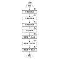
- FIG. 9 is a flowchart showing an operation example of the moving image transmission system 1.
- the moving image transmission system 1 repeatedly executes the processing of the flowchart shown in FIG.
- the operator is operating the input device 11b while gazing at a part of the operation device 31 and the operation object 32 displayed on the display device 11a of the information processing device 11. It is assumed that the information processing apparatus 11 transmits the operation information of the operator received by the input device 11b to the operation apparatus 31, and the operation apparatus 31 is operating according to the operation of the operator.
- the gaze area detection device 12 detects the gaze area of the display device 11a that the operator is looking at (step S1).
- the information processing apparatus 11 transmits the gaze area detected in step S1 to the moving image encoding apparatus 22 via the network 41 (step S2).
- the moving image encoding device 22 receives the gaze area transmitted in step S2 (step S3).
- the moving image encoding device 22 performs an encoding process on the image data output from the imaging camera 21 (step S4). For example, the moving image encoding device 22 performs an encoding process based on the gaze area received in step S3. The encoding process using the gaze area will be described using another flowchart.
- the moving image encoding device 22 transmits the moving image data encoded in step S4 to the information processing device 11 via the network 41 (step S5).
- the information processing apparatus 11 receives the moving image data transmitted in step S5 (step S6).
- the information processing device 11 displays the moving image data received in step S6 on the display device 11a (step S7).
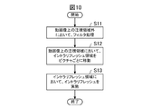
- FIG. 10 is a flowchart showing an operation example of the moving image encoding device 22.
- the flowchart of FIG. 10 shows a detailed operation example of step S4 of the flowchart of FIG. 9 and also shows an operation example of filter processing and intra refresh processing of the encoding processing performed by the moving image encoding device 22. Yes.
- the image processing unit 52 performs a filtering process on an area outside the gaze area of the image data of the moving image captured by the imaging camera 21 (step S11).
- control unit 61 moves the band-like intra refresh area for each picture in the gaze area on the moving image (step S12).
- control unit 61 performs intra refresh in the intra refresh area moved in step S12 (step S13).
- control unit 61 of the video encoding device 22 moves the intra refresh area smaller than the frame for each picture in the gaze area on the video, and the intra refresh is performed in the intra refresh area. Like that. Thereby, the moving image encoder 22 can further reduce the amount of codes as illustrated in FIG. 8, for example.
- the moving image encoding device 22 can transmit moving image data to the information processing device 11 at a low rate.
- the moving image encoding device 22 can allocate the information amount corresponding to the reduction in the code amount to the gaze area, and can further improve the image quality of the gaze area.
- the image processing unit 52 performs filter processing on image data outside the gaze area. Thereby, the moving image encoder 22 can reduce the amount of image information in a region (an unimportant region) that is not watched by the operator.
- the image processing unit 52 inputs moving image data for each predetermined line from the imaging camera 21 and performs a filtering process on data outside the gaze area.
- the control unit 61 performs control so that intra refresh is performed on the data of each predetermined line stored in the memory 54. Thereby, the moving image encoding device 22 can reduce the delay of moving image data transmission.
- control unit 61 may control the determination unit 65 so that the intra refresh is periodically performed not only in the gaze area but also outside the gaze area. In this case, the control unit 61 makes the refresh rate of the intra refresh in the gaze area higher than the refresh rate of the intra refresh outside the gaze area. As a result, the moving image encoding device 22 can reduce the amount of code and achieve a lower rate than the encoding processing described with reference to FIGS. 4, 5, and 6.
- control unit 61 may make the intra refresh area outside the gaze area smaller than the intra refresh area of the gaze area. Thereby, the moving image encoding device 22 can reduce the code amount in one frame, for example.
- control unit 61 may change the size of the intra refresh area according to the size of the gaze area.
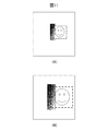
- FIG. 11 is a diagram for explaining an example of changing the size of the intra refresh area.
- the dotted line frames shown in FIGS. 11A and 11B indicate the gaze area, and the black band indicates the intra refresh area.
- FIG. 11A shows an example of an intra refresh area when the gaze area is small.
- FIG. 11B shows an example of an intra-refresh area when the gaze area is larger than that in FIG.
- the control unit 61 is a band-like intra refresh area whose vertical direction is several pixels to several tens of pixels larger than the vertical direction of the gaze area and whose horizontal direction is smaller than the horizontal direction of the gaze area. Intra refresh is performed to cover the gaze area.
- control unit 61 increases the band-like intra refresh area when the gaze area increases.
- control unit 61 is a band-like intra refresh area in which the vertical direction is several pixels to several tens of pixels larger than the vertical direction of the gaze area and the horizontal direction is smaller than the horizontal direction of the gaze area. Intra refresh is performed to cover the area.
- control unit 61 changes the size of the intra refresh area according to the size of the gaze area.
- the image processing unit 52 may perform filter processing so as to reduce the image information of the gaze area as the intra refresh area becomes larger.
- the image processing unit 52 may perform a filter process so that image information outside the gaze area is further reduced. Thereby, the moving image encoder 22 can suppress the increase in the amount of codes and achieve uniformization.
- the moving image encoding device 22 changes the size of the intra refresh area according to the error status of the stream output destination communication channel (according to the reception error status of the moving image data of the information processing device 11). Also good.
- the information processing apparatus 11 feeds back a communication error situation of moving image data to the control unit 61 of the moving image encoding device 22.
- the control unit 61 increases the number of MBs constituting the intra refresh area.
- the error rate is low (for example, when the error rate does not exceed a predetermined threshold)
- the number of MBs constituting the intra refresh area is reduced.
- the moving image encoding device 22 can achieve high image quality and low rate in accordance with the error rate.
- the image processing unit 52 may change the gaze area or the image information outside the gaze area in accordance with the change in the size of the intra refresh area according to the error situation. For example, as described above, the image processing unit 52 may reduce the image information in the gaze area or outside the gaze area as the intra refresh area is increased.
- the gaze area moves greatly in the above embodiment, if the intra refresh is performed in order from the left as described above, it may take time until the point being watched by the operator is refreshed. In that case, it may be configured such that, in the central portion of the gaze area, an area that can be updated by one refresh is intra-refreshed, and then another gaze area is refreshed.
- the refresh method for the other gaze area can also be configured such that the intra refresh is performed sequentially from the left as described above or the donut-shaped area is refreshed sequentially from the inside to the outside with the gaze area as the center. With this configuration, even when the gaze area moves greatly, the central portion of the gaze point is quickly refreshed, improving usability.
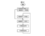
- FIG. 12 is a first flowchart illustrating an operation example of the information processing apparatus 11.
- FIG. 12 is a first flowchart illustrating an operation example of the information processing apparatus 11.
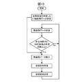
- FIG. 13 is a second flowchart illustrating an operation example of the information processing apparatus 11.
- the information processing apparatus 11 may perform an operation as illustrated in FIG.
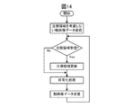
- FIG. 14 is a flowchart illustrating an operation example of the moving image encoding device 22.
- the moving image encoding device 22 may perform an operation as shown in FIG.
- the effect of performing the intra-refresh is improved by dividing the screen into slices (modes in which encoding is performed without using the surrounding image information) for each MB line. It becomes possible.
- the method of reducing the information amount in the image processing unit 52 has been described.
- the information amount may be reduced by the DCT / Q quantization control unit or the inter unit 64.
- a process for increasing the value of the quantization value (Q) other than the point of interest area relative to the point of interest, or specification of a mode of skipping inter prediction (with the same image as the reference image) in the region other than the point of interest Reduce the amount of information by actively
- the intra refresh rate may be changed according to the distance from the gazing point area.
- a normal camera device has an encoding device, and it is assumed that it is difficult to apply the present technology to this.
- the output of the camera device is configured to decode the video using the decoding device, and the video is encoded using the line-of-sight information for the video, and the stream May be configured to transmit.
- the present technology can be applied to a camera device in which an encoding device is already packaged.
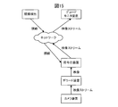
- FIG. 15 is a diagram illustrating another example of the moving image transmission system.
- the moving image transmission system may perform encoding by a system as shown in FIG.
- the present invention is not limited by the way of classification and names of the constituent elements.
- the configuration of the moving image encoding device 22 can be classified into more components depending on the processing content. Moreover, it can also classify
- each processing unit of the above-described flowchart is divided according to main processing contents in order to facilitate understanding of the processing of the moving image transmission system 1 and the moving image encoding device 22.
- the present invention is not limited by the way of dividing the processing unit or the name.
- the processing of the moving image transmission system 1 and the moving image encoding device 22 can be divided into more processing units according to the processing contents. Moreover, it can also divide
Landscapes
- Engineering & Computer Science (AREA)
- Multimedia (AREA)
- Signal Processing (AREA)
- Compression Or Coding Systems Of Tv Signals (AREA)
Abstract
動画像データの符号量をより低減する。 イントラ部は、動画像に対しイントラリフレッシュを実行する。制御部は、動画像上の注視領域において、フレームより小さいイントラリフレッシュ領域をピクチャごとに移動させ、イントラリフレッシュ領域においてイントラリフレッシュを行うように制御する。
Description
本発明は、動画像符号化装置および動画像符号化方法に関するものである。
特許文献1には、受信映像のうち注目する領域を高精細に得ることで経済的な映像通信を実現することが記載されている。
しかし、ユーザが注目していない領域においてもイントラリフレッシュを実施すると、動画像データの符号量が増えるという問題がある。
なお、特許文献1には、イントラリフレッシュをどのように実施するかについては何ら記載がない。
そこで本発明は、動画像データの符号量をより低減することができる技術を提供することを目的とする。
本願は、上記課題の少なくとも一部を解決する手段を複数含んでいるが、その例を挙げるならば、以下の通りである。上記課題を解決すべく、本発明に係る動画像符号化装置は、動画像に対しイントラリフレッシュを実行するイントラ部と、前記動画像上の注視領域において、フレームより小さいイントラリフレッシュ領域をピクチャごとに移動させ、前記イントラリフレッシュ領域において前記イントラリフレッシュを行うように制御する制御部と、を有することを特徴とする。
本発明によれば、動画像データの符号量をより低減することができる。上記した以外の課題、構成、および効果は、以下の実施形態の説明により明らかにされる。
以下、本発明の実施の形態を、図面を参照して説明する。
図1は、本発明に係る動画像符号化装置を用いた動画像伝送システム1の一例を示した図である。図1に示すように、動画像伝送システム1は、情報処理装置11と、注視領域検出装置12と、撮像カメラ21と、動画像符号化装置22と、操作装置31と、操作対象物32とを有している。情報処理装置11は、例えば、インターネットであるネットワーク41を介して、動画像符号化装置22および操作装置31と通信を行う。
情報処理装置11は、例えば、パーソナルコンピュータである。情報処理装置11は、表示装置11aと、入力装置11bとを有している。情報処理装置11の表示装置11aには、撮像カメラ21によって撮像される操作装置31および操作対象物32が表示される。
情報処理装置11を操作するオペレータは、情報処理装置11の表示装置11aに表示される操作装置31および操作対象物32を見ながら、例えば、ジョイスティックやマウス等の入力装置11bを操作し、操作装置31を遠隔操作する。
操作装置31は、例えば、ロボットである。操作装置31は、情報処理装置11の指示に従って動作し、操作対象物32に対して所定の操作を行う。
注視領域検出装置12は、オペレータが表示装置11aに表示されている画像のどの部分を見ているか検出する。以下では、オペレータが見ている画像の領域を注視領域と呼ぶことがある。
情報処理装置11は、注視領域検出装置12が検出した注視領域のデータを、ネットワーク41を介して、動画像符号化装置22へ送信する。以下では、情報処理装置11が送信する注視領域のデータを、単に注視領域と呼ぶことがある。
動画像符号化装置22は、撮像カメラ21が撮像した画像データを符号化し、ネットワーク41を介して、情報処理装置11へ送信する。ここで、一般的にオペレータは、撮像カメラ21が撮像した動画像の全領域を注視することはなく、操作装置31や操作対象物32の一部を注視している。そこで、動画像符号化装置22は、画像データを符号化する際、注視領域検出装置12が検出したオペレータの注視領域において、イントラリフレッシュを実行する。
すなわち、動画像符号化装置22は、撮像カメラ21が撮像した画像データの全領域に対してイントラリフレッシュを行うのではなく、オペレータが見ている画像領域(注視領域)において、イントラリフレッシュを実行する。
これにより、動画像符号化装置22は、オペレータの注視領域の画質低下を抑制しつつ、動画像データの符号量を低減することができる。また、動画像符号化装置22は、オペレータの注視領域の画質低下を抑制しつつ、動画像データを低レートで情報処理装置11へ送信することができる。
なお、動画像符号化装置22が適用されるシステムは、図1の例に限られず、動画像符号化装置22が適用されるシステムは、ロボット等の遠隔操作以外のシステムにも適用できる。例えば、監視カメラシステムのように操作装置31がない場合であっても監視者の注視領域を検出し、イントラリフレッシュする領域を決定してもよい。
また、上記では、情報処理装置11が、注視領域検出装置12によって検出された注視領域を動画像符号化装置22に送信するとしたが、注視領域検出装置12が、情報処理装置11を介することなく、検出した注視領域を動画像符号化装置22に送信してもよい。
また、操作装置31が、撮像カメラ21や動画像符号化装置22を備えていてもよい。
図2は、図1の動画像符号化装置22の機能ブロック例を示した図である。図2に示すように、動画像符号化装置22は、受信部51と、画像処理部52と、符号化部53と、メモリ54とを有している。
受信部51は、ネットワーク41を介して、情報処理装置11から、オペレータの注視領域を受信する。受信部51は、情報処理装置11から受信した注視領域を、制御部61と、画像処理部52とに出力する。
画像処理部52には、撮像カメラ21が撮像した動画像の画像データが入力される。画像処理部52は、受信部51によって受信された注視領域に基づき、画像データの注視領域外の領域に対して、フィルタ処理を行う(注視領域外の画像データをぼかす)。例えば、受信部51によって受信された注視領域の枠は、動画像上の座標で示され、画像処理部52は、その座標で示される枠外の画像データに対し、フィルタ処理を行う。
画像処理部52は、画像データのフィルタ処理を行う際、所定ラインずつフィルタ処理を行う。例えば、画像処理部52は、撮像カメラ21から出力される画像データを、ラスタスキャン順に入力し、入力した画像データを複数ライン保持し、注視領域外に対してフィルタ処理を行う。画像処理部52は、所定ラインずつ入力してフィルタ処理した画像データを、符号化部53に出力する。
符号化部53は、画像処理部52から出力される画像データに対して一旦メモリI/F部69に保持を行い、MB(Macro Block)単位で画像データを読み出し、動画像符号化を実施し、ストリーム情報を出力する。符号化部53は、制御部61と、画像入力部62と、イントラ部63と、インター部64と、判定部65と、DCT/Q(Discrete Cosine Transform/quantization)部66と、VLC(Variable Length Coding)部67と、送信部68と、メモリI/F(Inter Face)部69とを有している。
制御部61には、受信部51によって受信された注視領域が入力される。制御部61は、画像データの注視領域において、イントラリフレッシュが行われるように判定部65を制御する。
例えば、上記したように、受信部51によって受信される注視領域は、動画像上の座標で示される。制御部61は、例えば、注視領域の座標に基づいて、注視領域内のMBを判定し、そのMBにおいて、イントラリフレッシュが行われるように判定部65を制御する。
画像入力部62は、画像処理部52から出力される、フィルタ処理された画像データを、メモリI/F部69を介して、所定ラインずつメモリ54に格納する。例えば、画像入力部62は、画像処理部52から出力される画像データを、MBラインずつメモリ54に格納する。
イントラ部63は、メモリI/F部69を介して、メモリ54に記憶されている所定ライン分の画像データを読み出し、イントラ予測処理を実施する。
インター部64は、メモリI/F部69を介して、メモリ54に記憶されている所定ライン分の画像データを読み出し、インター予測処理を実施する。
判定部65は、イントラ部63のイントラ予測と、インター部64のインター予測とのどちらを採用するか判定する。例えば、判定部65は、イントラ予測を行った場合の画像データの情報量、インター予測を行った場合の画像データの情報量、およびその他のパラメータ等によって、イントラ部63のイントラ予測と、インター部64のインター予測とのどちらを採用するか判定する。判定部65は、採用した予測をDCT/Q部66に出力する。
なお、制御部61は、上記したように、画像データの注視領域においては、イントラリフレッシュが採用されるように判定部65を制御する。
DCT/Q部66は、判定部65によって判定された予測の予測誤差をDCT変換し、量子化する。
VLC部67は、DCT/Q部66によって量子化された画像情報と、判定部65が判定した符号化モードの情報とを符号化する。
送信部68は、VLC部67によって符号化された画像データを、ネットワーク41を介して、情報処理装置11へ送信する。
メモリI/F部69は、画像入力部62から出力される所定ラインずつの画像データや、復号画像、ストリーム等を、メモリ54に書き込む。また、メモリI/F部69は、イントラ予測処理が実行される画像データおよびインター予測処理が実行される画像データをメモリ54から読み出す。
メモリ54は、画像データを一時記憶するメモリである。
図2に示す動画像符号化装置22は、符号量の低減等を目的に、オペレータの注視領域を高画質に、それ以外の領域の画像情報を削減する。これにより、動画像符号化装置22は、注視領域の画質をキープしながら低レートの符号化を実現する。
図3は、図2の動画像符号化装置22の概略動作例を説明する図である。図3には、情報処理装置11の表示装置11aに表示される画像81が示してある。すなわち、画像81は、撮像カメラ21が撮像している画像である。図3では、操作装置31および操作対象32が撮像されている例を示している。
画像81中に示している点線枠82は、注視領域検出装置12によって検出されたオペレータの注視領域を示している。動画像符号化装置22の画像処理部52は、点線枠82に示す注視領域より外の領域に対して、例えば、ローパスフィルタ等を施す。すなわち、画像処理部52は、注視領域外の領域において、画像をぼかす処理(画像の情報量を減らす処理)を施し、情報処理装置11へ送信する画像データの情報量を削減する。
また、動画像符号化装置22の制御部61は、点線枠82に示す注視領域において、イントラリフレッシュが実行されるように制御する。すなわち、制御部61は、動画像の全領域ではなく、オペレータの注視領域において、イントラリフレッシュが実行されるように制御し、動画像データの符号量を低減する。そして、制御部61は、情報処理装置11へ送信する動画像データを低レート化する。
また、画像処理部52は、1画像の全データを、メモリ(図示せず)に記憶することなく、所定ラインずつの画像データに対し、フィルタ処理を実行する。符号化部53は、1画像の全データを、メモリに記憶することなく、所定ラインずつの画像データに対し、符号化処理を行う。このように、動画像符号化装置22は、所定ラインずつメモリに格納し、格納後直ちに処理を実行する構成となっている。これにより、動画像符号化装置22は、情報処理装置11への動画像データの送信の低遅延化を図ることができる。また、動画像データの低遅延化により、オペレータは、より実時間で操作装置31を操作でき、操作装置31の操作性が向上する。
なお、図3の例では、点線枠に示す注視領域を矩形としているが、人間の目と同様の楕円形や円形であってもよい。また、注視領域外の領域については、注視領域からの距離に応じて、画像をぼかす強度を強くする等の調整を施してもよい。これにより、動画像符号化装置22は、より低遅延で原画像加工処理を実施することができる。
図4は、符号化処理の例を説明する図である。図4には、矢印方向を時間軸として、入力されたフレームの符号化タイプが示してある。
動画像を見ながら、オペレータが操作装置を遠隔操作する場合、動画像データの符号化は、レートの均一化が求められる。そのため、符号化処理では、入力画像に対して、Pピクチャ(図4に示すP-pic)と呼ばれる過去のフレームのみを参照する符号化タイプが連続して使用される(先頭のフレームは、画面全面を静止画的に符号化するIピクチャ(図4に示すI-pic)とする)。
しかし、動画像データの伝送中にビット誤り等のエラーが発生すると、そのエラーが伝播してしまうという問題がある。そこで、符号化処理では、画像中の矩形の処理単位(MB)に対して、静止画的に符号化するイントラMBを各ピクチャで均等に帯状に配置(イントラリフレッシュ)する。これにより、符号化処理では、レートの平滑化とエラー伝播防止を実現している。
図5は、イントラリフレッシュの例を説明する図である。図5には、矢印方向を時間軸として、入力されたフレームの符号化タイプが示してある。また、図5に示す黒い帯は、イントラリフレッシュされる領域(イントラMB)を示している。
符号化処理では、各Pピクチャ内のMBに対して、画像毎に均等数で、位置をずらしながらイントラMB(図5に示す黒い帯)を配置する。これにより、動画像データのレートの均一化が可能となる。
図6は、符号化処理による動画像データのレート例を説明する図である。図6に示す縦軸は符号化処理による動画像データの符号量を示し、横軸は時間を示している。図6に示したようなイントラリフレッシュを行うことで、ある単位毎(例えば1フレーム)の符号量を、所定の転送レート(図6に示す点線)内に収まるように符号化することができる。また、図4に示したように、Pピクチャを連続して使用することにより、レートの均一化を図ることができる(レートが大きく変動しないようにすることができる)。
図4、図5、および図6で説明した符号化処理では、動画像中の重要領域を意識することなく、イントラリフレッシュ領域を配置する。そのため、図4、図5、および図6で説明した符号化処理では、オペレータが注視していない、重要でない領域に対しても、イントラ符号化を実施し、無駄に符号量を消費してしまう。これに対し、動画像符号化装置22では、オペレータが注視する注視領域において、イントラリフレッシュを行う。
図7は、動画像符号化装置22によるイントラリフレッシュを説明する図である。図7には、矢印方向を時間軸として、入力されたフレームの符号化タイプが示してある。また、図7に示す黒い帯は、イントラリフレッシュされる領域(イントラMB)を示している。また、図7に示す点線枠は、注視領域を示している。
図2に示した動画像符号化装置22の制御部61は、受信部51が受信した注視領域に基づいて、各Pピクチャ(図7に示すP-pic)に示す点線枠の注視領域において、その領域をカバーするように、イントラリフレッシュ領域(図7に示す黒い帯)を配置する。
例えば、制御部61は、垂直方向および水平方向が、フレームより小さい帯状のイントラリフレッシュ領域を、注視領域の全面をカバーするようにPピクチャごとに移動させ、そのイントラリフレッシュ領域において、イントラリフレッシュが実行されるように判定部65を制御する。
なお、イントラリフレッシュ領域は、インター予測の際の探索範囲より大きくすることが望ましい。
また、図7の例では、イントラリフレッシュ領域は、左から右へ移動されているが、右から左に移動されてもよい。また、イントラリフレッシュ領域は、上から下または下から上へ移動されてもよい。
また、注視領域の垂直方向または水平方向は、帯状のイントラリフレッシュ領域の垂直方向または水平方向より大きい場合がある。例えば、図7に示す点線枠の垂直方向は、黒い帯の垂直方向より大きい場合がある。この場合、制御部61は、イントラリフレッシュ領域が注視領域の全体をカバーするように、イントラリフレッシュ領域を走査させる(例えば、イントラリフレッシュ領域の水平方向の移動と、垂直方向の移動とを繰り返す)。
図8は、動画像符号化装置22の符号化処理による動画像データのレート例を説明する図である。図8に示す縦軸は動画像符号化装置22の符号化処理による動画像データの符号量を示し、横軸は時間を示している。図7に示したようなイントラリフレッシュを行うことで、図4、図5、および図6で説明した符号化処理の符号量(図8に示す点線)より、低レート化を図ることができる(図8に示す一点鎖線)。また、図7に示したように、Pピクチャを連続して使用することにより、レートの均一化を図ることができる(レートが大きく変動しないようにすることができる)。
図9は、動画像伝送システム1の動作例を示したフローチャートである。動画像伝送システム1は、図9に示すフローチャートの処理を繰り返し実行する。
なお、オペレータは、情報処理装置11の表示装置11aに映し出されている操作装置31や操作対象物32の一部を注視して、入力装置11bを操作しているとする。情報処理装置11は、入力装置11bが受付けたオペレータの操作情報を操作装置31に送信し、操作装置31は、オペレータの操作に従って、動作しているとする。
まず、注視領域検出装置12は、オペレータが見ている表示装置11aの注視領域を検出する(ステップS1)。
次に、情報処理装置11は、ステップS1にて検出された注視領域を、ネットワーク41を介して、動画像符号化装置22へ送信する(ステップS2)。
次に、動画像符号化装置22は、ステップS2にて送信された注視領域を受信する(ステップS3)。
次に、動画像符号化装置22は、撮像カメラ21から出力される画像データに対し、符号化処理を行う(ステップS4)。例えば、動画像符号化装置22は、ステップS3にて受信した注視領域に基づいて、符号化処理を行う。注視領域を用いた符号化処理については、別のフローチャートを用いて説明する。
次に、動画像符号化装置22は、ステップS4にて符号化処理した動画像データを、ネットワーク41を介して、情報処理装置11へ送信する(ステップS5)。
次に、情報処理装置11は、ステップS5にて送信された動画像データを受信する(ステップS6)。
次に、情報処理装置11は、ステップS6にて受信した動画像データを表示装置11aに表示する(ステップS7)。
図10は、動画像符号化装置22の動作例を示したフローチャートである。図10のフローチャートは、図9のフローチャートのステップS4の詳細な動作例を示すとともに、動画像符号化装置22が実施する符号化処理のうちの、フィルタ処理およびイントラリフレッシュ処理の動作例を示している。
まず、画像処理部52は、撮像カメラ21が撮像した動画像の画像データの注視領域外の領域に対して、フィルタ処理を行う(ステップS11)。
次に、制御部61は、動画像上の注視領域において、帯状のイントラリフレッシュ領域をピクチャごとに移動する(ステップS12)。
次に、制御部61は、ステップS12にて移動したイントラリフレッシュ領域において、イントラリフレッシュを実施する(ステップS13)。
以上説明したように、動画像符号化装置22の制御部61は、動画像上の注視領域において、フレームより小さいイントラリフレッシュ領域をピクチャごとに移動させ、そのイントラリフレッシュ領域において、イントラリフレッシュが行われるようにする。これにより、動画像符号化装置22は、例えば、図8に示したように、符号量をより低減することができる。
また、動画像符号化装置22は、動画像データを低レートで情報処理装置11に送信することができる。
また、動画像符号化装置22は、符号量の削減分の情報量を、注視領域に割り当てることができ、注視領域のさらなる高画質化を図ることも可能となる。
また、画像処理部52は、注視領域外の画像データに対し、フィルタ処理を行う。これにより、動画像符号化装置22は、オペレータが注視していない領域(重要でない領域)の画像情報量を低減することができる。
また、画像処理部52は、撮像カメラ21から所定ラインずつ動画像のデータを入力し、注視領域外のデータに対してフィルタ処理を行う。また、制御部61は、メモリ54に記憶された所定ラインずつのデータに対し、イントラリフレッシュが実行されるように制御する。これにより、動画像符号化装置22は、動画像データ送信の低遅延化を図ることができる。
なお、制御部61は、注視領域だけでなく、注視領域外においても、定期的にイントラリフレッシュが行われるように判定部65を制御してもよい。この場合、制御部61は、注視領域におけるイントラリフレッシュのリフレッシュレートを、注視領域外におけるイントラリフレッシュのリフレッシュレートよりも高くする。これにより、動画像符号化装置22は、図4、図5、および図6で説明した符号化処理より、符号量を低減し、低レート化を図ることができる。
また、制御部61は、注視領域外におけるイントラリフレッシュの領域を、注視領域のイントラリフレッシュ領域よりも小さくしてもよい。これにより、動画像符号化装置22は、例えば、1フレームにおける符号量の低減を図ることができる。
また、制御部61は、注視領域の大きさに応じて、イントラリフレッシュ領域の大きさを変更してもよい。
図11は、イントラリフレッシュ領域の大きさの変更例を説明する図である。図11の(A),(B)に示す点線枠は、注視領域を示し、黒い帯は、イントラリフレッシュ領域を示している。
図11の(A)には、注視領域が小さい場合のイントラリフレッシュ領域の例が示してある。図11の(B)には、図11の(A)より注視領域が大きい場合のイントラリフレッシュ領域の例が示してある。
制御部61は、図11の(A)に示すように、垂直方向が注視領域の垂直方向より数画素から数十画素大きく、水平方向が注視領域の水平方向より小さい帯状のイントラリフレッシュ領域で、注視領域をカバーするようにイントラリフレッシュを行う。
また、制御部61は、図11の(B)に示すように、注視領域が大きくなった場合、帯状のイントラリフレッシュ領域も大きくする。制御部61は、図11の(a)と同様に、垂直方向が注視領域の垂直方向より数画素から数十画素大きく、水平方向が注視領域の水平方向より小さい帯状のイントラリフレッシュ領域で、注視領域をカバーするようにイントラリフレッシュを行う。
このように、制御部61は、注視領域の大きさに応じて、イントラリフレッシュ領域の大きさを変更する。
なお、イントラリフレッシュ領域を大きくした場合は、動画像データの符号量が増加する。そこで、画像処理部52は、イントラリフレッシュ領域が大きくなるに従って、注視領域の画像情報を、低減するようにフィルタ処理を行ってもよい。または、画像処理部52は、注視領域外の画像情報を、より低減するようにフィルタ処理を行ってもよい。これにより、動画像符号化装置22は、符号量の増加を抑制し、均一化を図ることができる。
また、動画像符号化装置22は、ストリーム出力先の通信路のエラー状況に応じて(情報処理装置11の動画像データの受信エラー状況に応じて)、イントラリフレッシュ領域の大きさを変更してもよい。例えば、情報処理装置11は、動画像データの通信エラー状況を動画像符号化装置22の制御部61にフィードバックする。制御部61は、エラー率が高い場合には(例えば、エラー率が所定の閾値を超えた場合には)、イントラリフレッシュ領域を構成するMB数を多くする。反対に、エラー率が低い場合には(例えば、エラー率が所定の閾値を超えない場合には)、イントラリフレッシュ領域を構成するMB数を少なくする。これにより、動画像符号化装置22は、エラー率に応じた高画質化や低レート化が可能となる。
なお、画像処理部52は、エラー状況に応じたイントラリフレッシュ領域の大きさの変更に応じて、注視領域または注視領域外の画像情報を変更するようにしてもよい。例えば、画像処理部52は、上記したように、イントラリフレッシュ領域を大きくするに従って、注視領域または注視領域外における画像情報を少なくするようにしてもよい。
なお、上記の実施例において注視領域が大きく動いた場合に、上述したように左から順にイントラリフレッシュを行うとオペレータが注視している点がリフレッシュされるまでに時間がかかる可能性がある。その場合は、注視領域の中心部分のうち、1回のリフレッシュで更新できる領域をイントラリフレッシュし、その後に他の注視領域をリフレッシュするように構成してもよい。当該他の注視領域のリフレッシュの方法も、上述したように左から順にイントラリフレッシュする方法や注視領域を中心としてドーナツ状の領域を内側から外側に順にリフレッシュするように構成することができる。このように構成することで注視領域が大きく動いた場合でも注視点の中心部分が素早くリフレッシュされ、使い勝手が向上する。
また、注視領域が画面内に検出できない場合として、注視領域検出装置12にエラーが発生した場合や視線が画面外にある場合、本システムの起動時であってまだ視線情報が符号化装置に送付されていない場合、等が考えられる。このような場合は画面の中央部分を注視領域と設定する、もしくは、画面全体をネットワークで送信可能な符号量で均一に符号化し、画面全体を見渡せるようにするように構成してもよい。特に画面全体を均一に符号化することで、注視領域検出装置12にエラーが発生した場合であっても操作装置13の周辺の状況を把握しやすくすることができる。図12は、情報処理装置11の動作例を示したフローチャートのその1である。図13は、情報処理装置11の動作例を示したフローチャートのその2である。情報処理装置11は、図12または図13に示すような動作を行ってもよい。図14は、動画像符号化装置22の動作例を示したフローチャートである。動画像符号化装置22は、図14に示すような動作を行ってもよい。
なお、上記システムにおいては、画面をMBのライン毎にスライス(その周辺の画像情報を使わずに符号化を行うモード)に分割して符号化をする事で、イントラリフレッシュを行う効果をよりえることが可能となる。
また、上記実施例では、画像処理部52において、情報量を削減する手法を説明したが、本システムでは、DCT/Qの量子化制御部や、インター部64により情報量削減を行っても良い。例えば、注視点領域以外の量子化値(Q)の値を注視点に対して大きくする処理や、注視点以外の領域において、インター予測のスキップ(参照画像と同様の画像とする)モードの指定を積極的に行う事で、情報量の削減を実施する。
また、上記においては、注視点領域からの距離に応じて、イントラリフレッシュのレートの変更を行ってもよい。通常のカメラ装置は符号化装置を有しており、これに対して本技術を適用する事が難しい場合が想定される。このような場合には、カメラ装置の出力について、デコード装置を用いて映像のデコードを行うように構成し、その映像に対して視線情報を用いて上記実施例で説明した符号化を行い、ストリームを送信するように構成してもよい。このように構成する事で、既に符号化装置がパッケージ化されているカメラ装置についても、本技術を適用できるようになる。図15は、動画像伝送システムの他の例を示した図である。動画像伝送システムは、図15に示すようなシステムによって、符号化を行ってもよい。
以上、本発明について実施形態を用いて説明したが、動画像符号化装置22の構成を理解容易にするために、主な処理内容に応じて分類したものである。構成要素の分類の仕方や名称によって、本願発明が制限されることはない。動画像符号化装置22の構成は、処理内容に応じて、さらに多くの構成要素に分類することもできる。また、1つの構成要素がさらに多くの処理を実行するように分類することもできる。また、各構成要素の処理は、1つのハードウェアで実行されてもよいし、複数のハードウェアで実行されてもよい。
また、上述したフローチャートの各処理単位は、動画像伝送システム1および動画像符号化装置22の処理を理解容易にするために、主な処理内容に応じて分割したものである。処理単位の分割の仕方や名称によって、本願発明が制限されることはない。動画像伝送システム1および動画像符号化装置22の処理は、処理内容に応じて、さらに多くの処理単位に分割することもできる。また、1つの処理単位がさらに多くの処理を含むように分割することもできる。
また、本発明の技術的範囲は上記実施形態に記載の範囲には限定されない。上記実施形態に多様な変更または改良を加えることが可能であることが当業者には明らかである。また、そのような変更または改良を加えた形態も本発明の技術的範囲に含まれ得ることが、特許請求の範囲の記載から明らかである。
また、図面等において示した各構成の位置、大きさ、形状、範囲などは、発明の理解を容易にするため、実際の位置、大きさ、形状、範囲などを表していない場合がある。このため、本発明は、必ずしも、図面等に開示された位置、大きさ、形状、範囲などに限定されない。
1…動画像伝送システム、11…情報処理装置、11a…表示装置、11b…入力装置、12…注視領域検出装置、21…撮像カメラ、22…動画像符号化装置、31…操作装置、32…操作対象物、41…ネットワーク、51…受信部、52…画像処理部、53…符号化部、54…メモリ、61…制御部、62…画像入力部、63…イントラ部、64…インター部、65…判定部、66…DCT/Q部、67…VLC部、68…送信部、69…メモリI/F、81…画像、82…点線枠
Claims (10)
- 動画像に対しイントラリフレッシュを実行するイントラ部と、
前記動画像上の注視領域において、フレームより小さいイントラリフレッシュ領域をピクチャごとに移動させ、前記イントラリフレッシュ領域において前記イントラリフレッシュを行うように制御する制御部と、
を有することを特徴とする動画像符号化装置。 - 請求項1に記載の動画像符号化装置において、
前記制御部は、前記注視領域における前記イントラリフレッシュのリフレッシュレートを、前記動画像上の注視領域外における前記イントラリフレッシュのリフレッシュレートよりも高くする、
ことを特徴とする動画像符号化装置。 - 請求項2に記載の動画像符号化装置において、
前記動画像上の注視領域外における前記イントラリフレッシュの領域は、前記イントラリフレッシュ領域より小さい、
ことを特徴とする動画像符号化装置。 - 請求項1に記載の動画像符号化装置において、
前記制御部は、前記注視領域の大きさに応じて、前記イントラリフレッシュ領域の大きさを変更する、
ことを特徴とする動画像符号化装置。 - 請求項4に記載の動画像符号化装置において、
前記イントラリフレッシュ領域を大きくするに従って、前記注視領域または注視領域外における画像情報を少なくする画像処理部、
をさらに有することを特徴とする動画像符号化装置。 - 請求項1に記載の動画像符号化装置において、
ネットワークを介して、符号化した前記動画像のデータを情報処理装置に送信する送信部、をさらに有し、
前記制御部は、前記情報処理装置から送信される前記データのエラーに関する情報に基づいて、前記イントラリフレッシュ領域の大きさを変更する、
ことを特徴とする動画像符号化装置。 - 請求項6に記載の動画像符号化装置において、
前記イントラリフレッシュ領域を大きくするに従って、前記注視領域または注視領域外における画像情報を少なくする画像処理部、
をさらに有することを特徴とする動画像符号化装置。 - 請求項1に記載の動画像符号化装置において、
撮像カメラから所定ラインずつ前記動画像のデータを入力し、注視領域外のデータに対してフィルタ処理を行う画像処理部、
をさらに有することを特徴とする動画像符号化装置。 - 請求項8に記載の動画像符号化装置において、
前記画像処理部から出力される前記データを所定ラインずつ入力する画像入力部と、
前記データを記憶装置に記憶するインタフェース部と、をさらに有し、
前記制御部は、前記記憶部に記憶された所定ラインずつの前記データに対し、前記イントラリフレッシュが実行されるように制御する、
ことを特徴とする動画像符号化装置。 - 動画像上の注視領域において、フレームより小さいイントラリフレッシュ領域をピクチャごとに移動し、
前記イントラリフレッシュ領域において、イントラリフレッシュを行うように制御する、
ことを特徴とする動画像符号化方法。
Priority Applications (1)
| Application Number | Priority Date | Filing Date | Title |
|---|---|---|---|
| PCT/JP2016/062845 WO2017183204A1 (ja) | 2016-04-22 | 2016-04-22 | 動画像符号化装置および動画像符号化方法 |
Applications Claiming Priority (1)
| Application Number | Priority Date | Filing Date | Title |
|---|---|---|---|
| PCT/JP2016/062845 WO2017183204A1 (ja) | 2016-04-22 | 2016-04-22 | 動画像符号化装置および動画像符号化方法 |
Publications (1)
| Publication Number | Publication Date |
|---|---|
| WO2017183204A1 true WO2017183204A1 (ja) | 2017-10-26 |
Family
ID=60115831
Family Applications (1)
| Application Number | Title | Priority Date | Filing Date |
|---|---|---|---|
| PCT/JP2016/062845 Ceased WO2017183204A1 (ja) | 2016-04-22 | 2016-04-22 | 動画像符号化装置および動画像符号化方法 |
Country Status (1)
| Country | Link |
|---|---|
| WO (1) | WO2017183204A1 (ja) |
Citations (7)
| Publication number | Priority date | Publication date | Assignee | Title |
|---|---|---|---|---|
| JPH02237287A (ja) * | 1989-03-10 | 1990-09-19 | Nec Corp | 画像信号フレーム間予測符号化装置のリフレッシュ方式 |
| JPH05161130A (ja) * | 1991-12-06 | 1993-06-25 | Canon Inc | 動画像信号符号化制御方式及びその装置 |
| JPH10136339A (ja) * | 1996-10-30 | 1998-05-22 | Sharp Corp | 画像情報伝送装置 |
| US6304295B1 (en) * | 1998-09-18 | 2001-10-16 | Sarnoff Corporation | Region-based refresh strategy for video compression |
| JP2005295215A (ja) * | 2004-03-31 | 2005-10-20 | Victor Co Of Japan Ltd | 動画像符号化装置 |
| JP2013093650A (ja) * | 2011-10-24 | 2013-05-16 | Sony Corp | 符号化装置、符号化方法、およびプログラム |
| JP2014519247A (ja) * | 2011-05-04 | 2014-08-07 | カビウム・インコーポレイテッド | エンドツーエンドコード化ビデオ伝送システムのためのオンデマンドイントラリフレッシュ |
-
2016
- 2016-04-22 WO PCT/JP2016/062845 patent/WO2017183204A1/ja not_active Ceased
Patent Citations (7)
| Publication number | Priority date | Publication date | Assignee | Title |
|---|---|---|---|---|
| JPH02237287A (ja) * | 1989-03-10 | 1990-09-19 | Nec Corp | 画像信号フレーム間予測符号化装置のリフレッシュ方式 |
| JPH05161130A (ja) * | 1991-12-06 | 1993-06-25 | Canon Inc | 動画像信号符号化制御方式及びその装置 |
| JPH10136339A (ja) * | 1996-10-30 | 1998-05-22 | Sharp Corp | 画像情報伝送装置 |
| US6304295B1 (en) * | 1998-09-18 | 2001-10-16 | Sarnoff Corporation | Region-based refresh strategy for video compression |
| JP2005295215A (ja) * | 2004-03-31 | 2005-10-20 | Victor Co Of Japan Ltd | 動画像符号化装置 |
| JP2014519247A (ja) * | 2011-05-04 | 2014-08-07 | カビウム・インコーポレイテッド | エンドツーエンドコード化ビデオ伝送システムのためのオンデマンドイントラリフレッシュ |
| JP2013093650A (ja) * | 2011-10-24 | 2013-05-16 | Sony Corp | 符号化装置、符号化方法、およびプログラム |
Similar Documents
| Publication | Publication Date | Title |
|---|---|---|
| US11330262B2 (en) | Local image enhancing method and apparatus | |
| US11539974B2 (en) | Multidimensional quantization techniques for video coding/decoding systems | |
| US11190775B2 (en) | System and method for reducing video coding fluctuation | |
| KR101298389B1 (ko) | 비디오 코더 및 디코더 공동 최적화를 위한 방법 및 시스템 | |
| JP5268743B2 (ja) | 画像通信システム | |
| US8493499B2 (en) | Compression-quality driven image acquisition and processing system | |
| US20120195356A1 (en) | Resource usage control for real time video encoding | |
| US10027966B2 (en) | Apparatus and method for compressing pictures with ROI-dependent compression parameters | |
| US11025933B2 (en) | Dynamic video configurations | |
| JP2006513634A (ja) | 符号化ストリーム中で伝送されたイントラ予測モードに基づく空間的誤り隠蔽 | |
| JP6707334B2 (ja) | リアルタイム符号化のための方法及び装置 | |
| CN108632527A (zh) | 控制器、摄像机以及用于控制摄像机的方法 | |
| JP5694674B2 (ja) | 画像符号化装置、画像符号化復号化システム、画像符号化方法、画像表示方法 | |
| WO2017183204A1 (ja) | 動画像符号化装置および動画像符号化方法 | |
| WO2019167546A1 (ja) | 映像符号化装置及び映像符号化方法 | |
| Laddha et al. | Bitrate and complexity optimizations for video conferencing systems | |
| WO2013073422A1 (ja) | 動画像符号化装置 | |
| US20190373270A1 (en) | Efficient coding of video data in the presence of video annotations | |
| JP2004297266A (ja) | 動画像圧縮装置 | |
| JP2007274114A (ja) | 画像符号化装置及び画像符号化方法 | |
| JPH06113288A (ja) | 情報源符号化制御装置 | |
| JPH11234679A (ja) | 強制画面更新装置 |
Legal Events
| Date | Code | Title | Description |
|---|---|---|---|
| NENP | Non-entry into the national phase |
Ref country code: DE |
|
| 121 | Ep: the epo has been informed by wipo that ep was designated in this application |
Ref document number: 16899476 Country of ref document: EP Kind code of ref document: A1 |
|
| 122 | Ep: pct application non-entry in european phase |
Ref document number: 16899476 Country of ref document: EP Kind code of ref document: A1 |
|
| NENP | Non-entry into the national phase |
Ref country code: JP |