WO2017183257A1 - パンツ型の吸収性物品、及び、パンツ型の吸収性物品の製造方法 - Google Patents
パンツ型の吸収性物品、及び、パンツ型の吸収性物品の製造方法 Download PDFInfo
- Publication number
- WO2017183257A1 WO2017183257A1 PCT/JP2017/004377 JP2017004377W WO2017183257A1 WO 2017183257 A1 WO2017183257 A1 WO 2017183257A1 JP 2017004377 W JP2017004377 W JP 2017004377W WO 2017183257 A1 WO2017183257 A1 WO 2017183257A1
- Authority
- WO
- WIPO (PCT)
- Prior art keywords
- waistline
- ventral
- absorbent article
- waistline portion
- region
- Prior art date
- Legal status (The legal status is an assumption and is not a legal conclusion. Google has not performed a legal analysis and makes no representation as to the accuracy of the status listed.)
- Ceased
Links
Images




Classifications
-
- A—HUMAN NECESSITIES
- A61—MEDICAL OR VETERINARY SCIENCE; HYGIENE
- A61F—FILTERS IMPLANTABLE INTO BLOOD VESSELS; PROSTHESES; DEVICES PROVIDING PATENCY TO, OR PREVENTING COLLAPSING OF, TUBULAR STRUCTURES OF THE BODY, e.g. STENTS; ORTHOPAEDIC, NURSING OR CONTRACEPTIVE DEVICES; FOMENTATION; TREATMENT OR PROTECTION OF EYES OR EARS; BANDAGES, DRESSINGS OR ABSORBENT PADS; FIRST-AID KITS
- A61F13/00—Bandages or dressings; Absorbent pads
- A61F13/15—Absorbent pads, e.g. sanitary towels, swabs or tampons for external or internal application to the body; Supporting or fastening means therefor; Tampon applicators
-
- A—HUMAN NECESSITIES
- A61—MEDICAL OR VETERINARY SCIENCE; HYGIENE
- A61F—FILTERS IMPLANTABLE INTO BLOOD VESSELS; PROSTHESES; DEVICES PROVIDING PATENCY TO, OR PREVENTING COLLAPSING OF, TUBULAR STRUCTURES OF THE BODY, e.g. STENTS; ORTHOPAEDIC, NURSING OR CONTRACEPTIVE DEVICES; FOMENTATION; TREATMENT OR PROTECTION OF EYES OR EARS; BANDAGES, DRESSINGS OR ABSORBENT PADS; FIRST-AID KITS
- A61F13/00—Bandages or dressings; Absorbent pads
- A61F13/15—Absorbent pads, e.g. sanitary towels, swabs or tampons for external or internal application to the body; Supporting or fastening means therefor; Tampon applicators
- A61F13/45—Absorbent pads, e.g. sanitary towels, swabs or tampons for external or internal application to the body; Supporting or fastening means therefor; Tampon applicators characterised by the shape
- A61F13/49—Absorbent pads, e.g. sanitary towels, swabs or tampons for external or internal application to the body; Supporting or fastening means therefor; Tampon applicators characterised by the shape specially adapted to be worn around the waist, e.g. diapers, nappies
- A61F13/496—Absorbent pads, e.g. sanitary towels, swabs or tampons for external or internal application to the body; Supporting or fastening means therefor; Tampon applicators characterised by the shape specially adapted to be worn around the waist, e.g. diapers, nappies in the form of pants or briefs
Definitions
- the present invention relates to a pant-type absorbent article and a method for manufacturing a pant-type absorbent article.
- a leg opening region is formed in a side portion of the crotch portion, and a front waistline portion and a rear waistline portion are integrated by a joint portion.
- a pants-type disposable diaper in which an opening region is formed is known.
- the front waistline part and the rear waistline part have the same shape, such as when the upper end of the front waistline part and the upper end of the rear waistline part match, as in the pants-type disposable diaper described in Patent Document 1, the diaper It is difficult to judge before and after. In that case, it is necessary to check the characters and the like written on the diaper, and the diaper cannot be worn smoothly.
- the present invention has been made in view of the above problems, and an object thereof is to provide a pant-type absorbent article that can be easily determined before and after.
- a main invention for achieving the above object is an absorbent main body having a longitudinal direction and a transverse direction intersecting with the longitudinal direction and having an absorbent core for absorbing excrement, and one end of the absorbent main body.
- Back side waistline part located on the side, abdominal side waistline part located on the other end side of the absorbent main body, and both ends of the back side waistline part in the lateral direction, the ventral side waistline part in the lateral direction
- a pants-type absorbent article having a pair of joining regions joined to each other, wherein the upper end of the back waistline portion in the longitudinal direction is more than the upper end of the ventral waistline portion in the longitudinal direction.
- Pants type characterized in that a high-density region having a higher density than the surroundings is provided at both ends in the lateral direction of the upper end portion of the back-side waistline portion. This is an absorbent article.
- FIG. 7A is a schematic plan view of a diaper of a modified example in an extended state
- FIG. 7B is a schematic cross-sectional view in a bonding region of the diaper of the modified example.
- FIG. 8A is a schematic development view of the diaper of the second embodiment in the extended state
- FIG. 8B is a schematic plan view of the diaper of the second embodiment in the extended state.
- An absorptive body having an absorptive core having a longitudinal direction and a transverse direction intersecting the longitudinal direction and absorbing excrement; a dorsal waist part located on one end side of the absorptive body; A pair of joining regions in which both end portions of the abdominal waistline portion in the lateral direction are joined to both end portions of the backside waistline portion in the lateral direction; The upper end portion of the back waistline portion in the longitudinal direction is located above the upper end of the ventral waistline portion in the longitudinal direction, and is located above the longitudinal direction.
- a pants-type absorbent article characterized in that a high-density region having a higher density than the surroundings is provided at both ends in the lateral direction of the upper end portion of the back waistline portion.
- the back waistline part is larger than the abdominal waistline part because it covers the buttocks, so that it is easy to determine the front and back of the absorbent article.
- the rigidity of the part that protrudes increases and is difficult to break.
- the joining region has a plurality of welding regions, the high-density region is recessed in the thickness direction of the back waistline portion, and the upper end of the joining region in the longitudinal direction
- the pants-type absorbent article is characterized in that the pattern of the welded region in the section and the pattern of the high-density region are the same. According to such an absorbent article, the boundary of a welding area
- region is not conspicuous, and the fall of the external appearance of a diaper can be suppressed. Moreover, a high-density area
- the pant-type is characterized in that, in the joining region, the upper side of the ventral waist part in the longitudinal direction is folded back and joined to the back waist part. It is an absorbent article. According to such an absorbent article, since the number of materials laminated
- This absorbent article is a pant-type absorption device characterized in that a cut portion is provided at the upper end of the abdominal waistline portion in the center of the abdominal waistline portion in the lateral direction. It is a sex product. According to such an absorbent article, contact with a wearer's navel etc. can be suppressed. Moreover, it becomes much easier to determine before and after the absorbent article.
- the length in the vertical direction of the upper end portion of the dorsal waist part located above the upper end of the ventral waist part is longer than the cut part.
- a pant-type absorbent article characterized by being shorter than the length in the longitudinal direction. According to such an absorbent article, the length of the back side waistline part which protrudes from the abdominal side waistline part is prevented from becoming unnecessarily long, and the protruding part is more difficult to break.
- a plurality of elastic members extending and contracting in the lateral direction are arranged at intervals in the longitudinal direction on the ventral waist part, and the cut portion and the longitudinal position are the same.
- the lengthwise spacing of a plurality of elastic members is a pants-type absorbent article characterized in that the position in the vicinity of the cut portion is wider than the position in the vicinity of the joining region.
- a plurality of elastic members extending and contracting in the lateral direction are arranged at intervals in the longitudinal direction on the back waistline portion, and in the vicinity of the joining region, the back waistline portion
- the pant-type absorption is characterized in that the vertical displacement between the elastic member and the elastic member at the ventral waist part is smaller on the lower side than on the upper side in the vertical direction. It is a sex product.
- the upper end portion of the back waistline portion protrudes from the abdominal waistline portion, and at the lower portion, the positional deviation between the elastic member of the backside waistline portion and the elastic member of the abdominal waistline portion.
- the absorbent body having a longitudinal direction and a transverse direction intersecting with the longitudinal direction and having an absorbent core that absorbs excrement, and a back waistline portion located on one end side of the absorbent body.
- a pair of joints in which both end portions of the abdominal waistline portion in the lateral direction are joined to both end portions of the back waistline portion in the lateral direction and a ventral waistline portion located on the other end side of the absorbent main body A method of manufacturing a pants-type absorbent article in which a plurality of elastic members extending and contracting in the lateral direction are arranged at an interval in the longitudinal direction on the region, the back side waistline portion, and the abdominal side waistline portion, The dorsal waistline member in which the dorsal waistline portion is continuous in the lateral direction and the abdominal waistline member in which the abdominal waistline portion is continuous in the lateral direction are extended in the conveying direction along the lateral direction.
- the absorbent main body having a longitudinal direction in the intersecting direction with an interval in the transport direction, and among the ventral waistline members, the abdomen in the lateral direction Forming a cut portion at a central portion of the side waistline portion and corresponding to an upper end of the abdominal waistline portion; and after forming the cut portion, the dorsal waistline member and the ventral waistline belt
- the absorbent main body is folded at the center in the intersecting direction so as to overlap with a member to form the joining region, and outside the end on the cut portion side of the ventral waistline portion in the intersecting direction Forming a high-density region having a higher density than the surrounding at the end of the back waistline portion located at the back, and from the back waistband member and the ventral waistband member, the backside waistline and the Ventral waist And disconnecting the a method of manufacturing an absorbent article of the pant type, characterized in that it comprises a.
- the manufacturing method of such an absorbent article after forming the cut portion in the stretched ventral waistline member, and forming the joining region, the upper end portion of the dorsal waistline portion is separated from the ventral waistline portion. It is possible to manufacture an absorbent article that jumps out and is easy to determine before and after.
- pant-type absorbent article according to the present invention will be described by taking a pant-type disposable diaper as an example.
- FIG. 1 is a perspective view of a pants-type disposable diaper 1 (hereinafter referred to as a diaper).
- FIG. 2 is a schematic development view of the diaper 1 in an extended state, and is a view in a state where the elastic member of the diaper 1 is extended to such an extent that the wrinkles generated in the diaper 1 cannot be visually recognized.
- FIG. 3 is a schematic cross-sectional view at the central portion in the lateral direction of the diaper 1 of FIG.
- the diaper 1 has a vertical direction and a horizontal direction that intersect each other.
- the diaper 1 is a so-called three-piece type, which is applied to the wearer's crotch part and absorbs excrement such as urine, and a back waistline part 20 that covers the back side part of the wearer. And an abdomen waist part 30 covering the abdomen side of the wearer.
- the longitudinal directions of the back waistline portion 20 and the abdominal waistline portion 30 are along the lateral direction of the diaper 1, and the backside waistline portion 20 and the abdominal waistline portion 30 are in the longitudinal direction of the diaper 1.
- the absorptive main body 10 is spanned between both parts 20 and 30 in the state arrange
- the central portion in the lateral direction of the back waistline portion 20 is located at one end side in the longitudinal direction of the absorbent main body 10, and the lateral direction of the ventral side waistline portion 30 in the other end side in the longitudinal direction of the absorbent main body 10. The central part of is located.
- the diaper 1 is equipped with a pair of joining area
- the absorbent main body 10 includes a liquid-permeable top sheet 11 (for example, non-woven fabric), an absorber 12, a liquid-impermeable back sheet 13 (for example, a sheet made of polyethylene or polypropylene), and an exterior sheet 14 (for example, non-woven fabric). And a pair of side sheets 15 (for example, a liquid-impermeable nonwoven fabric).
- a liquid-permeable top sheet 11 for example, non-woven fabric
- an absorber 12 for example, a liquid-impermeable back sheet 13 (for example, a sheet made of polyethylene or polypropylene), and an exterior sheet 14 (for example, non-woven fabric).
- a pair of side sheets 15 for example, a liquid-impermeable nonwoven fabric.
- the absorbent body 12 includes an absorbent core 121 formed by laminating a liquid absorbent material (for example, pulp fiber or superabsorbent polymer), and a liquid-permeable core wrap (not shown, for example, non-woven fabric or tissue) that covers the absorbent core 121. ).
- the absorbent core 121 may not be covered with the core wrap.
- the absorptive core 121 of this embodiment is a substantially hourglass shape in plan view, and the lateral width W1 is maximum at the end 121a of the absorptive core 121 in the vertical direction.
- the pair of side sheets 15 are provided on both sides of the absorbent main body 10 in the lateral direction.
- An elastic member 151 (for example, a rubber thread or an elastic sheet) that expands and contracts in the vertical direction is provided at the outer end of the side sheet 15 in the horizontal direction. Accordingly, both side portions of the absorbent main body 10 in the lateral direction constitute a so-called leg gather LG and fit around the wearer's leg.
- the inner end portion of the side seat 15 in the lateral direction is folded outward in the lateral direction, and an elastic member (not shown) that expands and contracts in the vertical direction is provided in the folded portion. Therefore, the inner side edge part of the side seat
- the back waistline portion 20 has a rectangular shape in plan view, an inner layer sheet 21 (for example, non-woven fabric) positioned on the skin side in the thickness direction, an outer layer sheet 22 (for example, non-woven fabric) positioned on the non-skin side, and in the lateral direction. And a plurality of elastic members 23 that are arranged along the side and extend in the lateral direction. The plurality of elastic members 23 are fixed in an expanded state between the inner layer sheet 21 and the outer layer sheet 22.
- a rubber thread is illustrated as the elastic member 23, and the elastic member 23 is hereinafter also referred to as a back-side rubber thread 23.
- thirteen backside rubber threads 23 are arranged in the backside waistline portion 20 at intervals in the vertical direction.
- the ventral waist part 30 has a rectangular shape in plan view, an inner layer sheet 31 (for example, non-woven fabric) positioned on the skin side in the thickness direction, an outer layer sheet 32 (for example, non-woven fabric) positioned on the non-skin side, and in the lateral direction. It has the some elastic member 33 arrange
- the plurality of elastic members 33 are fixed in an extended state between the inner layer sheet 31 and the outer layer sheet 32.
- a rubber thread is exemplified as the elastic member 33, and the elastic member 33 is hereinafter also referred to as a ventral side rubber thread 33.
- two abdominal side rubber threads 33a (hereinafter also referred to as upper abdominal side rubber thread 33a) whose vertical position is equal to that of the cut part 34, and ten abdominal parts below the cut part 34.
- Side thread rubbers 33b (hereinafter also referred to as lower belly side rubber threads 33b) are arranged at intervals in the vertical direction.
- the diaper 1 fits around the waist of the wearer by the back side rubber thread 23 and the ventral side rubber thread 33.
- the elastic members 23 and 33 arranged in the back waistline portion 20 and the abdominal waistline portion 30 are not limited to thread rubber, and may be, for example, thread-like polyurethane stretchable fibers or the like, or a sheet-like elastic member.
- the back-side thread rubber 23 and the ventral-side thread rubber 33 are provided from one end to the other end in the lateral direction of the back-side waistline part 20 and the abdominal side waistline part 30.
- the back side rubber thread 23 and the ventral side rubber thread 33 whose longitudinal positions are the same as those of the absorbent core 12 are discontinuous on the absorbent core 12.
- the upper ventral side rubber thread 33 a is discontinuous at the cut portion 34.
- the cut part 34 has a circular arc shape that protrudes downward, and is provided at the center of the ventral waist part 30 in the lateral direction and at the upper end 30 a of the ventral waist part 30.
- the navel of a newborn is wet.
- a clip may be attached to the navel of a newborn to prevent bleeding. Therefore, the cut part 34 can prevent the clip attached to the wearer's navel or navel from hitting the diaper 1.
- even if it is the diaper 1 in which the cut part 34 was provided it is good not only for newborns but also for infants and adults.
- the width W2 (for example, 85 mm) of the cut portion 34 in the horizontal direction is smaller than the maximum width W1 (for example, 120 mm) of the absorbent core 121. Therefore, the lateral width of the cut portion 34 is not unnecessarily wide, and the length of the upper ventral side rubber thread 33a disposed on both sides in the lateral direction of the cut portion 34 can be secured. Therefore, the diaper 1 (ventral side waist part 30) fits a wearer's waist.
- the width W2 of the cut portion 34 and the maximum width W1 of the absorbent core 121 may be measured in a state in which the ventral waist portion 30 is extended to such an extent that wrinkles generated in the ventral waist portion 30 are not visible. .
- the cut portion 34 is not limited to the arc shape, but may be rectangular, for example. In the case of the cut portion 34 formed in this way, the design is easy. Further, a straight slit having a predetermined length in the vertical direction may be used as the cut portion 34. In this case, the manufacture is facilitated, and a cut-off portion does not occur during the manufacture. Even if it is a slit, it spreads in the lateral direction when worn, so that the wearer's navel or clip can be prevented from hitting the diaper 1.
- the upper end part of the back side waistline part 20 in the vertical direction is located above the upper end 30a of the ventral side waistline part 30 in the vertical direction.
- surroundings is provided in the both ends in a horizontal direction among the upper end parts of the back side waist part 20 (it mentions later for details).
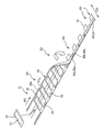
- FIG. 4 is a diagram for explaining a method of manufacturing the diaper 1.
- a plurality of diapers 1 are continuously manufactured while the material of the diaper 1 is transported in the transport direction MD along the lateral direction of the diaper 1.
- a cross direction CD that intersects the transport direction MD is along the longitudinal direction of the diaper 1.
- a back side waistband member 24 in which the back side waistline portion 20 is laterally continuous, a ventral side waistband member 35 in which the abdominal side waistline portion 30 is laterally continuous, and the absorbent main body 10 are not shown. It is manufactured by the process. And the back side waistband member 24 and the abdominal side waistband member 35 are conveyed in the state which arranged in parallel at intervals in the cross direction CD. There, the absorbent main body 10 whose longitudinal direction runs along the cross direction CD merges with a gap in the transport direction MD, and is joined to the dorsal waistband member 24 and the ventral waistband member 35 (S1).
- the backside thread rubber 23 and the stomachside thread that are continuous between the belt members of the inner layer sheets 21 and 31 and the belt members of the outer layer sheets 22 and 32, respectively.
- the rubber 33 is fixed in an extended state in the transport direction MD.
- the back waistline belt member 24 and the abdominal waistband member 35 extend in the transport direction MD to the extent that no wrinkles occur in the back waistline member 24 and the abdominal waistline member 35. It is conveyed in the state.
- the dimensions of the band members of the inner layer sheets 21 and 31 and the band members of the outer layer sheets 22 and 32 constituting the back side waistline member 24 and the abdominal side waistline member 35 coincide with the dimensions of the members alone or to it. It is conveyed in a stretched state until the length is close.
- the outer end 35a in the cross direction CD of the ventral waistline member 35 is cut out in an arc shape at every product pitch in the transport direction MD (S2).
- the cut part 34 is formed in the site
- the absorbent main body 10 is folded at the center of the cross direction CD so that the back waistline member 24 and the abdominal waistline member 35 overlap (S3). Thereafter, a pair of joining regions 40a and 40b are formed at every product pitch in the transport direction MD.
- One joining region 40a becomes the joining region 40 of the upstream diaper 1
- the other joining region 40b becomes the joining region 40 of the downstream diaper 1.
- the high-density region 50 is formed at the end portion of the back waistline member 24 positioned outside the outer end 35a (end on the cut portion side) of the ventral waistline member 35 in the cross direction CD. Is done.
- the high-density area 50a of the upstream diaper 1 is formed at a position equal to the position in the transport direction MD of one joining area 40a, and the downstream position at a position equal to the position in the transport direction MD of the other joining area 40b.
- a high-density region 50b of the side diaper 1 is formed (S4).
- the back waistband member 24 and the abdominal waistband member 35 are cut at a cutting line along the crossing direction CD between the pair of joining regions 40a, 40b. Then, the back waistline portion 20 and the abdominal waistline portion 30 are separated from the back side waistline member 24 and the abdominal waistline member 35, and the diaper 1 is manufactured (S5).
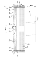
- FIG. 5 is a schematic plan view of the extended diaper 1.
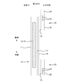
- FIG. 6 is a view for explaining the back side rubber thread 23 and the ventral side rubber thread 33 around the joining region 40.
- the cut portion 34 is formed on the abdominal waistline member 35 in a state where the dorsal waistline member 24 and the abdominal waistline member 35 are stretched and transported in the transport direction MD. Then, the back waistline member 24 and the abdominal waistband member 35 are joined to form the joint region 40.
- both sides of the cut portion 34 are discontinuous in the transport direction MD corresponding to the lateral direction of the diaper 1, and the stretched state is not maintained and can be deformed.
- the upper belly side rubber thread 33a is disposed on both sides of the cut part 34, and therefore both sides of the cut part 34 contract. Accordingly, when the dorsal waistline member 24 and the abdominal waistline member 35 are overlapped (S3 in FIG. 4), the outer side 35a of the abdominal waistline member 35 in the cross direction CD is located outside the cross direction CD. The end portion of the back waistline member 24 protrudes outward. In this state, the junction region 40 is formed. Therefore, in the individually separated diaper 1, as shown in FIG. 5, the upper end portion 20 ⁇ / b> A of the back waistline portion 20 in the vertical direction is higher than the upper end 30 a of the ventral waistline portion 30 in the vertical direction. Will be located.
- the upper end 30 a of the ventral waist part 30 is inclined downward from the lateral center toward the end. Therefore, of the upper end 20 a of the back side waistline portion 20, both end portions in the horizontal direction are positioned above the abdominal side waistline portion 30 in the vertical direction, and the portion in the vicinity of the cut portion 34 is connected to the upper end 30 a of the abdominal side waistline portion 30. Match. In this way, at least a part of the upper end portion 20 ⁇ / b> A of the back waistline portion 20 including the both end portions in the lateral direction only needs to be positioned above the upper end 30 a of the abdominal waistline portion 30 in the vertical direction.
- the back waistline portion 20 is protruded from the upper end 30a of the abdominal waistline portion 30, so that the shape of the backside waistline portion 20 and the shape of the abdominal waistline portion 30 are different.
- the user can recognize that there is a difference between the front and rear of the diaper 1. Therefore, it can suppress that the diaper 1 will be worn accidentally back and forth.
- the back waistline 20 is larger than the ventral waistline 30 because it covers the buttocks.
- the user can make a diaper back-and-forth determination without checking the characters or the like described in the diaper 1.
- the diaper 1 can be installed smoothly.
- region 50 is provided in the both ends in the horizontal direction among the upper ends 20A of the back side waistline part 20 located in the upper side of the vertical direction rather than the upper end 30a of the abdominal side waistline part 30.
- FIG. in the high density region 50 the fiber density of the inner layer sheet 21 and the outer layer sheet 22 included in the back side waistline portion 20 is higher than the surroundings.
- the high-density region 50 and the surrounding region have the same basis weight (g / m 2 ), and the back-side waistline portion 20 is compressed in the thickness direction so that the high-density region 50 is formed.
- the high-density region 50 is a recessed region that is thinner than the surrounding region.
- the present invention is not limited thereto, and the high-density region 50 and the surrounding region may have the same thickness, and the basis weight of the fibers may be different.
- the back waistline part 20 and the abdomen waistline part 30 are soft members formed of a nonwoven fabric or the like. Therefore, by providing the high-density region 50 at the upper end portion 20A of the back side waistline portion 20 that protrudes from the abdominal side waistline portion 30, the upper end portion 20A of the back side waistline portion 20 is difficult to break and the shape is easily maintained. Therefore, it is possible to prevent the excrement from leaking from the gap caused by the folds of the upper end portion 20A of the back waistline portion 20 and the appearance deterioration.
- the back-side waistline portion 20 even if the high-density region 50 is small.
- the upper end 20A can be made difficult to break. Therefore, compared with the case where the absorptive core 121 is made to exist in the upper end part 20A so that the upper end part 20A of the back side waist part 20 is not easily broken, the uncomfortable feeling at the time of wearing can be reduced.
- the density comparison between the high density region 50 and the surrounding region may be performed by a known method. For example, a cross section obtained by cutting the upper end portion 20A of the back waistline portion 20 in the thickness direction is photographed with an electron microscope or the like, and the fiber density difference between the high-density region 50 and the surrounding region is visually compared. Compare the number of fibers.
- the basis weight (g / cm 2 ) is calculated by cutting out the high-density region 50 and the surrounding region from the upper end 20A of the back waistline portion 20 and dividing the mass of each region by the area.
- the fiber density (g / cm 3 ) may be calculated by dividing the amount by the thickness.
- the joining method of the pair of joining regions 40 is welding (for example, heat welding, ultrasonic welding, welding by laser irradiation, etc.), and the joining region 40 has a plurality of welding regions 41 (concave portions).
- the welding region 41 illustrated in FIG. 5 has a substantially rectangular shape inclined with respect to the horizontal direction, and two rows of the welding regions 41 arranged in the vertical direction at intervals are formed, and the two rows are shifted in the vertical direction. ing.
- three high-density regions 50 having the same shape and the same size as the welding region 41 are arranged in the same manner as the welding region 41 at both ends in the lateral direction of the upper end portion 20A of the back waistline portion 20. Is provided. Note that the number of high-density regions 50 is not limited to three.
- the pattern of the welding region 41 and the pattern of the high-density region 50 may be the same.
- region 40 illustrated in FIG. 5 although the same shape and the same magnitude
- the pattern of the welding region 41 at the upper end portion of the bonding region 40 in the vertical direction and the pattern of the high-density region 50 are preferably made the same. By doing so, the boundary of the welding area
- the present invention is not limited to the above, and the pattern of the welding region 41 and the pattern of the high-density region 50 at the upper end portion of the bonding region 40 may be different.
- the high-density region 50 is a region that is recessed in the thickness direction of the back waistline portion 20 similarly to the welding region 41. Therefore, a high-density region can be formed by the same formation method as the welding region 41, and the diaper 1 can be easily manufactured.
- the joining region 40 and the high-density region 50 are provided at both ends in the lateral direction of the back waistline portion 20. Therefore, a device for welding the joining region 40, for example, a pair of rollers provided with a plurality of protrusions on the outer peripheral surface of one roller (embossing roller), passes through the back waistband member 24 and the abdominal waistband member 35.
- the high density region 50 can be formed at the same timing as the formation of the weld region 40.
- the diaper 1 can be easily manufactured by forming the joining region 40 and the high-density region 50 in the same apparatus and in the same process.
- the pattern of the welding region at the upper end of the joining region 40 and the pattern of the high-density region 50 are made the same so that the dosing position of the back waistband member 24 and the abdominal waistband member 35 with respect to the welding apparatus Can be formed in the direction CD intersecting the transport direction, the weld region 40 and the high-density region 50 can be formed.
- the diaper 1 is provided with a cut portion 34 at a central portion of the abdominal waistline portion 30 in the lateral direction and at an upper end 30 a of the abdominal waistline portion 30. Is provided.
- the back waistline portion 20 is not provided with a cut portion. Therefore, the difference before and after the diaper 1 becomes clearer, and the front and rear determination of the diaper 1 becomes much easier.
- the longitudinal length L1 of the back waistline portion 20 and the longitudinal length L1 of the ventral waistline portion 30 are equal in the expanded and extended state shown in FIG. .
- the cut portion 34 is provided in the ventral waist part 30, and the upper belly side rubber thread 33a is disposed on both sides in the lateral direction of the cut part 34.
- the stretched ventral waist part The junction region 40 may be formed after the cut portion 34 is formed in the portion 30. By doing so, the joining region 40 can be formed by contracting both side portions in the lateral direction of the cut portion 34 of the ventral waist portion 30. Therefore, the upper end portion 20 ⁇ / b> A of the back side waistline portion 20 can be positioned above the upper end 30 a of the ventral side waistline portion 30 in the vertical direction.
- the length (maximum length) L2 in the vertical direction of the upper end portion 20A of the dorsal waist portion 20 located on the upper side in the vertical direction from the upper end 30a of the ventral waist portion 30 is larger. It is preferable to make the cut portion 34 shorter than the length (maximum depth) L3 in the vertical direction (L2 ⁇ L3). By doing so, it is possible to prevent the length of the upper end portion 20 ⁇ / b> A of the back side waistline portion 20 protruding from the ventral side waistline portion 30 from becoming unnecessarily long. Therefore, the upper end portion 20A of the back waistline portion 20 is more difficult to break and the shape is easily maintained.
- the vertical distance d between the upper ventral side rubber threads 33a is equal, and the vertical distance d between the lower ventral side rubber threads 33b is equal.
- the distance d is designed to be equal.
- two upper ventral side rubber threads having the same vertical position as the cut portion 34 in the vicinity of the joining region 40.
- the vertical distance d1 between 33a is narrower than the vertical distance d2 between ten lower ventral rubber threads 33b arranged below the cut portion 34 in the vertical direction.
- the joint region 40 is formed in a state where both side portions in the lateral direction of the cut portion 34 in the ventral waist part 30 are contracted. In this way, both side portions in the lateral direction of the cut portion 34 are contracted to form the joining region 40, and the vertical interval d1 between the upper ventral side rubber threads 33a is set as the vertical interval d2 between the lower ventral side rubber yarns 33b.
- the upper end portion 30A of the back waistline portion 30 can be positioned above the upper end 20a of the ventral waistline portion 20 in the vertical direction.
- the lengths in the vertical direction from the rubber 33 to the upper end 30a of the ventral waist part 30 are equal. That is, in the pants-type diaper 1 in which the joining region 40 is formed, the back-side thread rubber 23 and the ventral-side thread rubber 33 are arranged so that the longitudinal positions thereof are aligned.
- the elastic member 23 of the back side waistline part 20 and the elastic member 33 of the abdominal side waistline part 30 are shown in the vicinity of the joining area
- the vertical position shift is smaller on the lower side than on the upper side in the vertical direction.
- both side portions in the lateral direction of the cut portion 34 are contracted.
- the appearance of the diaper 1 is deteriorated by minimizing the vertical displacement between the lower ventral rubber thread 33b disposed below the cut portion 34 and the corresponding back rubber thread 23 as much as possible. Can be suppressed.
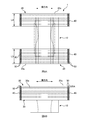
- FIG. 7A is a schematic plan view of the diaper 1 of the modified example in an extended state
- FIG. 7B is a schematic cross-sectional view in the bonding region 40 of the diaper 1 of the modified example.
- FIG. 5 the case where the ventral waist part 30 contracts by the manufacturing method (FIG. 4) of the diaper 1 in which the joining region 40 is formed after the cut part 34 is formed is taken as an example. Not limited to this.
- region 40 was formed in the state by which the both sides in the horizontal direction of the cut part 34 among the ventral waist parts 30 were turned back may be sufficient.
- the joining region 40 is formed in a state in which the corner portion 36 of the ventral side waistline portion 30 is folded back. Also in this case, the upper end portion 20A of the back waistline portion 20 can be positioned above the upper end 30a of the ventral waistline portion 30 in the vertical direction. Therefore, it is possible to easily determine the diaper 1 before and after.
- the joining region 40 when the upper end portion (corner portion 36) of the ventral side waistline portion 30 in the vertical direction is folded back, As shown to 7B, the number of materials laminated
- FIG. 8A is a schematic development view of the diaper 1 of the second embodiment in the extended state
- FIG. 8B is a schematic plan view of the diaper 1 of the second embodiment in the extended state.
- the length L5 in the longitudinal direction of the dorsal waist part 20 is longer than the length L4 in the longitudinal direction of the abdominal waist part 30 in the expanded and extended state. Is longer.
- the upper end 20A of the back waist part 20 is positioned above the upper end 30a of the ventral waist part 30 in the vertical direction as shown in FIG. 8B. It is possible to position the diaper 1 before and after.
- the cut part may be formed in the ventral waist part 30 also in this case.
- segmented into three parts was illustrated, it is not restricted to this, The diaper in which the back side waistline part 20 and the abdominal side waistline part 30 were formed integrally, the back side waistline part 20, and the ventral side
- the diaper in which the waist part 30 and the absorptive main body 10 were integrally formed may be sufficient.
- 1 Diaper (pants-type absorbent article), 1a waist opening, 1b leg opening, 10 absorbent body, 11 top sheet, 12 absorbent body, 121 absorbent core, 13 back sheet, 14 exterior sheet, 15 side sheet , 20 dorsal waist part, 21 inner layer sheet, 22 outer layer sheet, 23 elastic member, 24 dorsal waist part belt member, 30 ventral waist part, 31 inner layer sheet, 32 outer layer sheet, 33 elastic member, 33a upper belly side rubber thread 33b Lower ventral side rubber band, 34 cut part, 35 ventral waistline member, 40 joining area, 41 welding area, 50 high density area, LG leg gather, LSG solid gather
Landscapes
- Health & Medical Sciences (AREA)
- Epidemiology (AREA)
- Engineering & Computer Science (AREA)
- Biomedical Technology (AREA)
- Heart & Thoracic Surgery (AREA)
- Vascular Medicine (AREA)
- Life Sciences & Earth Sciences (AREA)
- Animal Behavior & Ethology (AREA)
- General Health & Medical Sciences (AREA)
- Public Health (AREA)
- Veterinary Medicine (AREA)
- Absorbent Articles And Supports Therefor (AREA)
Abstract
Description
このような吸収性物品によれば、一般に背側胴回り部は臀部を覆うため腹側胴回り部よりも大きいと考えられるので、吸収性物品の前後判断が容易となる。また、腹側胴回り部から飛び出た背側胴回り部に高密度領域を設けることで、その飛び出た部位の剛性が高まり、折れ難くなる。
このような吸収性物品によれば、溶着領域と高密度領域との境界が目立ち難く、おむつの外観の低下を抑制できる。また、溶着領域と同じ形成方法により高密度領域を形成でき、吸収性物品の製造を容易にできる。
このような吸収性物品によれば、腹側胴回り部及び接合領域の上端部において積層される資材点数が増えるため、腹側胴回り部の上端部の折り返りや腹側へのめくれを抑えられる。また接合領域の破損を抑制できる。
このような吸収性物品によれば、着用者の臍等への接触を抑制できる。また、吸収性物品の前後判断がより一層容易となる。
このような吸収性物品によれば、腹側胴回り部から飛び出る背側胴回り部の長さが不要に長くなることを防ぎ、その飛び出た部位がより折れ難くなる。
このような吸収性物品によれば、カット部近傍の腹側胴回り部の剛性を下げられるため、着用者の臍周辺のデリケートな部位に吸収性物品が柔らかく当接する。
このような吸収性物品によれば、背側胴回り部の上端部を腹側胴回り部から飛び出させつつ、下方側の部位では背側胴回り部の弾性部材と腹側胴回り部の弾性部材との位置ずれを小さくすることで、吸収性物品の外観の低下を抑制できる。
このような吸収性物品の製造方法によれば、伸長状態の腹側胴回り帯部材にカット部を形成した後に、接合領域を形成することで、背側胴回り部の上端部が腹側胴回り部から飛び出て、前後判断が容易な吸収性物品を製造できる。
<おむつ1の基本構成>
図1はパンツ型の使い捨ておむつ1(以下、おむつ)の斜視図である。図2は伸長状態のおむつ1の概略展開図であり、おむつ1に生じていた皺が視認できなくなる程度まで、おむつ1が有する弾性部材を伸長した状態での図である。図3は図2のおむつ1の横方向における中央部での概略断面図である。おむつ1は、互いに交差する縦方向と横方向とを有する。また、おむつ1は、所謂3ピースタイプであり、着用者の股間部にあてがわれ尿等の排泄物を吸収する吸収性本体10と、着用者の背側部を覆う背側胴回り部20と、着用者の腹側部を覆う腹側胴回り部30とを備える。
図4は、おむつ1の製造方法を説明する図である。本実施形態では、おむつ1の材料がおむつ1の横方向に沿った搬送方向MDに搬送されながら複数のおむつ1が連続的に製造されるとする。また、搬送方向MDと交差する交差方向CDはおむつ1の縦方向に沿う。
図5は、伸長状態のおむつ1の概略平面図である。図6は、接合領域40周辺の背側糸ゴム23及び腹側糸ゴム33を説明する図である。前述のように、おむつ1の製造方法では、背側胴回り帯部材24及び腹側胴回り帯部材35が搬送方向MDに伸長されて搬送されている状態で、腹側胴回り帯部材35にカット部34が形成され、その後に背側胴回り帯部材24及び腹側胴回り帯部材35が接合されて接合領域40が形成される。
図7Aは、伸長状態である変形例のおむつ1の概略平面図であり、図7Bは、変形例のおむつ1の接合領域40における概略断面図である。前述の実施例(図5)では、カット部34の形成後に接合領域40が形成されるおむつ1の製造方法(図4)によって、腹側胴回り部30が収縮する場合を例に挙げているが、これに限らない。腹側胴回り部30のうちカット部34の横方向における両側部が折り返された状態で接合領域40が形成されたおむつ1でもよい。図7Aでは、腹側胴回り部30の角部36が折り返された状態で接合領域40が形成されている。この場合にも、背側胴回り部20の上端部20Aを腹側胴回り部30の上端30aよりも縦方向の上側に位置させることができる。よって、おむつ1の前後判断を容易にできる。
図8Aは、伸長状態である第2実施形態のおむつ1の概略展開図であり、図8Bは、伸長状態である第2実施形態のおむつ1の概略平面図である。第2実施形態のおむつ1では、図8Aに示すように、展開且つ伸長状態において、腹側胴回り部30の縦方向の長さL4に比べて、背側胴回り部20の縦方向の長さL5の方が長くなっている。この場合、腹側胴回り部30にカット部が形成されていなくとも、図8Bに示すように、背側胴回り部20の上端部20Aを腹側胴回り部30の上端30aよりも縦方向の上側に位置させることができ、おむつ1の前後判断を容易にできる。但し、この場合にも腹側胴回り部30にカット部が形成されていてもよい。
上記実施形態は、本発明の理解を容易にするためのものであり、本発明を限定して解釈するためのものではない。本発明は、その趣旨を逸脱することなく、変更・改良され得ると共に、本発明には、その等価物が含まれることは言うまでもない。
Claims (8)
- 縦方向と、前記縦方向と交差する横方向とを有し、
排泄物を吸収する吸収性コアを備えた吸収性本体と、
前記吸収性本体の一端側に位置する背側胴回り部と、
前記吸収性本体の他端側に位置する腹側胴回り部と、
前記横方向における前記背側胴回り部の両端部に、前記横方向における前記腹側胴回り部の両端部を接合した一対の接合領域と、を備えるパンツ型の吸収性物品であって、
前記縦方向における前記背側胴回り部の上端部が、前記縦方向における前記腹側胴回り部の上端よりも前記縦方向の上側に位置し、
前記背側胴回り部の前記上端部のうち前記横方向における両端部に、密度が周囲よりも高い高密度領域が設けられていることを特徴とするパンツ型の吸収性物品。 - 請求項1に記載のパンツ型の吸収性物品であって、
前記接合領域は、複数の溶着領域を有し、
前記高密度領域は、前記背側胴回り部の厚さ方向に凹んでおり、
前記縦方向における前記接合領域の上端部での前記溶着領域のパターンと、前記高密度領域のパターンとが、同じであることを特徴とするパンツ型の吸収性物品。 - 請求項1又は請求項2に記載のパンツ型の吸収性物品であって、
前記接合領域では、前記縦方向における前記腹側胴回り部の上端部が折り返された状態で、前記背側胴回り部に接合されていることを特徴とするパンツ型の吸収性物品。 - 請求項1から請求項3の何れか1項に記載のパンツ型の吸収性物品であって、
前記横方向における前記腹側胴回り部の中央部であって、前記腹側胴回り部の前記上端に、カット部が設けられていることを特徴とするパンツ型の吸収性物品。 - 請求項4に記載のパンツ型の吸収性物品であって、
前記腹側胴回り部の前記上端よりも前記縦方向の上側に位置する前記背側胴回り部の前記上端部の前記縦方向の長さの方が、前記カット部の前記縦方向の長さに比べて短いことを特徴とするパンツ型の吸収性物品。 - 請求項4又は請求項5に記載のパンツ型の吸収性物品であって、
前記腹側胴回り部には、前記横方向に伸縮する複数の弾性部材が前記縦方向に間隔を空けて配置され、
前記カット部と前記縦方向の位置が同じである複数の弾性部材の前記縦方向の間隔は、前記カット部の近傍の位置での方が、前記接合領域の近傍の位置に比べて、広いことを特徴とするパンツ型の吸収性物品。 - 請求項6に記載のパンツ型の吸収性物品であって、
前記背側胴回り部には、前記横方向に伸縮する複数の弾性部材が前記縦方向に間隔を空けて配置され、
前記接合領域の近傍において、前記背側胴回り部の前記弾性部材と前記腹側胴回り部の前記弾性部材との前記縦方向の位置ずれが、前記縦方向の上側に比べて下側の方が小さくなっていることを特徴とするパンツ型の吸収性物品。 - 縦方向と、前記縦方向と交差する横方向とを有し、
排泄物を吸収する吸収性コアを備えた吸収性本体と、
前記吸収性本体の一端側に位置する背側胴回り部と、
前記吸収性本体の他端側に位置する腹側胴回り部と、
前記横方向における前記背側胴回り部の両端部に、前記横方向における前記腹側胴回り部の両端部を接合した一対の接合領域と、
前記背側胴回り部及び前記腹側胴回り部に、前記横方向に伸縮する複数の弾性部材が前記縦方向に間隔を空けて配置されたパンツ型の吸収性物品の製造方法であって、
前記背側胴回り部が前記横方向に連続した背側胴回り帯部材、及び、前記腹側胴回り部が前記横方向に連続した腹側胴回り帯部材を、前記横方向に沿った搬送方向に伸長し且つ前記搬送方向と交差する方向に間隔を空けて並べた状態で搬送するとともに、前記交差する方向に長手方向が沿った前記吸収性本体を、前記搬送方向に間隔を空けて搬送することと、
前記腹側胴回り帯部材のうち、前記横方向における前記腹側胴回り部の中央部であって、前記腹側胴回り部の上端に対応する部位に、カット部を形成することと、
前記カット部の形成後に、前記背側胴回り帯部材と前記腹側胴回り帯部材とが重なるように、前記吸収性本体を前記交差する方向の中央部で折り、前記接合領域を形成するとともに、前記交差する方向における前記腹側胴回り部の前記カット部側の端よりも外側に位置する前記背側胴回り部の端部に、密度が周囲よりも高い高密度領域を形成することと、
前記背側胴回り帯部材及び前記腹側胴回り帯部材から、前記背側胴回り部及び前記腹側胴回り部を切り離すことと、
を有することを特徴とするパンツ型の吸収性物品の製造方法。
Priority Applications (4)
| Application Number | Priority Date | Filing Date | Title |
|---|---|---|---|
| BR112018070545-4A BR112018070545B1 (pt) | 2016-04-19 | 2017-02-07 | Artigo absorvente de vestir |
| MYPI2018703471A MY186084A (en) | 2016-04-19 | 2017-02-07 | Pull-on absorbent article and method for manufacturing pull-on absorbent article |
| CN201780024912.4A CN109069319B (zh) | 2016-04-19 | 2017-02-07 | 套穿式吸收性物品与用于制造套穿式吸收性物品方法 |
| EA201892357A EA035692B1 (ru) | 2016-04-19 | 2017-02-07 | Надеваемое впитывающее изделие |
Applications Claiming Priority (2)
| Application Number | Priority Date | Filing Date | Title |
|---|---|---|---|
| JP2016083533A JP6419103B2 (ja) | 2016-04-19 | 2016-04-19 | パンツ型の吸収性物品 |
| JP2016-083533 | 2016-04-19 |
Publications (1)
| Publication Number | Publication Date |
|---|---|
| WO2017183257A1 true WO2017183257A1 (ja) | 2017-10-26 |
Family
ID=60115861
Family Applications (1)
| Application Number | Title | Priority Date | Filing Date |
|---|---|---|---|
| PCT/JP2017/004377 Ceased WO2017183257A1 (ja) | 2016-04-19 | 2017-02-07 | パンツ型の吸収性物品、及び、パンツ型の吸収性物品の製造方法 |
Country Status (6)
| Country | Link |
|---|---|
| JP (1) | JP6419103B2 (ja) |
| CN (1) | CN109069319B (ja) |
| BR (1) | BR112018070545B1 (ja) |
| EA (1) | EA035692B1 (ja) |
| MY (1) | MY186084A (ja) |
| WO (1) | WO2017183257A1 (ja) |
Families Citing this family (3)
| Publication number | Priority date | Publication date | Assignee | Title |
|---|---|---|---|---|
| CN111315334B (zh) * | 2017-11-10 | 2021-11-26 | 尤妮佳股份有限公司 | 一次性尿布 |
| JP7321974B2 (ja) * | 2020-05-28 | 2023-08-07 | ユニ・チャーム株式会社 | パンツ型吸収性物品 |
| JP2023026803A (ja) * | 2021-08-16 | 2023-03-01 | 花王株式会社 | パンツ型吸収性物品 |
Citations (6)
| Publication number | Priority date | Publication date | Assignee | Title |
|---|---|---|---|---|
| JPH10127689A (ja) * | 1996-11-06 | 1998-05-19 | Uni Charm Corp | 使い捨てのパンツ型おむつ |
| WO2004054482A1 (ja) * | 2002-12-13 | 2004-07-01 | Hakujuji Kabushiki Kaisha | 使い捨て吸収性物品 |
| WO2010070477A2 (en) * | 2008-12-15 | 2010-06-24 | Kimberly-Clark Worldwide, Inc. | Absorbent article with waist relief feature |
| JP2010200912A (ja) * | 2009-03-02 | 2010-09-16 | Uni Charm Corp | 吸収性物品の折り畳み方法 |
| JP2012192115A (ja) * | 2011-03-18 | 2012-10-11 | Oji Nepia Co Ltd | 使い捨ておむつ |
| JP2013042861A (ja) * | 2011-08-23 | 2013-03-04 | Kao Corp | パンツ型吸収性物品 |
-
2016
- 2016-04-19 JP JP2016083533A patent/JP6419103B2/ja active Active
-
2017
- 2017-02-07 MY MYPI2018703471A patent/MY186084A/en unknown
- 2017-02-07 EA EA201892357A patent/EA035692B1/ru not_active IP Right Cessation
- 2017-02-07 WO PCT/JP2017/004377 patent/WO2017183257A1/ja not_active Ceased
- 2017-02-07 CN CN201780024912.4A patent/CN109069319B/zh active Active
- 2017-02-07 BR BR112018070545-4A patent/BR112018070545B1/pt active IP Right Grant
Patent Citations (6)
| Publication number | Priority date | Publication date | Assignee | Title |
|---|---|---|---|---|
| JPH10127689A (ja) * | 1996-11-06 | 1998-05-19 | Uni Charm Corp | 使い捨てのパンツ型おむつ |
| WO2004054482A1 (ja) * | 2002-12-13 | 2004-07-01 | Hakujuji Kabushiki Kaisha | 使い捨て吸収性物品 |
| WO2010070477A2 (en) * | 2008-12-15 | 2010-06-24 | Kimberly-Clark Worldwide, Inc. | Absorbent article with waist relief feature |
| JP2010200912A (ja) * | 2009-03-02 | 2010-09-16 | Uni Charm Corp | 吸収性物品の折り畳み方法 |
| JP2012192115A (ja) * | 2011-03-18 | 2012-10-11 | Oji Nepia Co Ltd | 使い捨ておむつ |
| JP2013042861A (ja) * | 2011-08-23 | 2013-03-04 | Kao Corp | パンツ型吸収性物品 |
Also Published As
| Publication number | Publication date |
|---|---|
| EA201892357A1 (ru) | 2019-02-28 |
| CN109069319B (zh) | 2020-06-05 |
| EA035692B1 (ru) | 2020-07-27 |
| BR112018070545B1 (pt) | 2023-02-14 |
| CN109069319A (zh) | 2018-12-21 |
| JP6419103B2 (ja) | 2018-11-07 |
| JP2017192485A (ja) | 2017-10-26 |
| MY186084A (en) | 2021-06-20 |
| BR112018070545A2 (pt) | 2019-02-12 |
Similar Documents
| Publication | Publication Date | Title |
|---|---|---|
| KR101486975B1 (ko) | 팬츠형 흡수성 물품 | |
| JP5250407B2 (ja) | 使い捨てパンツ型おむつおよびその製造方法 | |
| JP6397947B2 (ja) | パンツ型吸収性物品 | |
| JP6118703B2 (ja) | 吸収性物品 | |
| JP2018033529A (ja) | 吸収性物品 | |
| CN210330913U (zh) | 短裤型吸收性物品 | |
| JP5902845B1 (ja) | 使い捨ての着用物品 | |
| JP2015058226A (ja) | 使い捨て着用物品 | |
| JP6419103B2 (ja) | パンツ型の吸収性物品 | |
| KR102419798B1 (ko) | 흡수성 물품 및 팬티형 흡수성 물품의 제조 방법 | |
| JP6255203B2 (ja) | 吸収性物品 | |
| JP6255225B2 (ja) | 吸収性物品 | |
| JP6364346B2 (ja) | 使い捨ておむつ | |
| JP6709842B2 (ja) | 吸収性物品 | |
| KR101844207B1 (ko) | 흡수성 물품 | |
| JP6469038B2 (ja) | 使い捨ておむつ | |
| KR101844208B1 (ko) | 흡수성 물품 | |
| JP6709843B2 (ja) | 吸収性物品 | |
| JP6236420B2 (ja) | 吸収性物品 | |
| JP2016002391A (ja) | パンツ型吸収性物品 | |
| JP7321974B2 (ja) | パンツ型吸収性物品 | |
| JP3210618U (ja) | パンツ型吸収性物品 | |
| WO2016104721A1 (ja) | 使い捨ておむつ | |
| JP6427482B2 (ja) | 使い捨ておむつ | |
| KR20170099943A (ko) | 일회용 기저귀 |
Legal Events
| Date | Code | Title | Description |
|---|---|---|---|
| REG | Reference to national code |
Ref country code: BR Ref legal event code: B01A Ref document number: 112018070545 Country of ref document: BR |
|
| NENP | Non-entry into the national phase |
Ref country code: DE |
|
| 121 | Ep: the epo has been informed by wipo that ep was designated in this application |
Ref document number: 17785602 Country of ref document: EP Kind code of ref document: A1 |
|
| ENP | Entry into the national phase |
Ref document number: 112018070545 Country of ref document: BR Kind code of ref document: A2 Effective date: 20181005 |
|
| 122 | Ep: pct application non-entry in european phase |
Ref document number: 17785602 Country of ref document: EP Kind code of ref document: A1 |