WO2017183269A1 - Conduit d'admission d'air - Google Patents
Conduit d'admission d'air Download PDFInfo
- Publication number
- WO2017183269A1 WO2017183269A1 PCT/JP2017/005406 JP2017005406W WO2017183269A1 WO 2017183269 A1 WO2017183269 A1 WO 2017183269A1 JP 2017005406 W JP2017005406 W JP 2017005406W WO 2017183269 A1 WO2017183269 A1 WO 2017183269A1
- Authority
- WO
- WIPO (PCT)
- Prior art keywords
- air intake
- duct
- duct body
- wire mesh
- water droplets
- Prior art date
- Legal status (The legal status is an assumption and is not a legal conclusion. Google has not performed a legal analysis and makes no representation as to the accuracy of the status listed.)
- Ceased
Links
Images

Classifications
-
- F—MECHANICAL ENGINEERING; LIGHTING; HEATING; WEAPONS; BLASTING
- F02—COMBUSTION ENGINES; HOT-GAS OR COMBUSTION-PRODUCT ENGINE PLANTS
- F02M—SUPPLYING COMBUSTION ENGINES IN GENERAL WITH COMBUSTIBLE MIXTURES OR CONSTITUENTS THEREOF
- F02M35/00—Combustion-air cleaners, air intakes, intake silencers, or induction systems specially adapted for, or arranged on, internal-combustion engines
- F02M35/10—Air intakes; Induction systems
-
- F—MECHANICAL ENGINEERING; LIGHTING; HEATING; WEAPONS; BLASTING
- F02—COMBUSTION ENGINES; HOT-GAS OR COMBUSTION-PRODUCT ENGINE PLANTS
- F02M—SUPPLYING COMBUSTION ENGINES IN GENERAL WITH COMBUSTIBLE MIXTURES OR CONSTITUENTS THEREOF
- F02M35/00—Combustion-air cleaners, air intakes, intake silencers, or induction systems specially adapted for, or arranged on, internal-combustion engines
- F02M35/16—Combustion-air cleaners, air intakes, intake silencers, or induction systems specially adapted for, or arranged on, internal-combustion engines characterised by use in vehicles
Definitions
- the present invention relates to an intake duct.
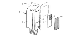
- an intake duct b extending in the vertical direction is installed on the rear surface of the cab a.
- a duct body d having an outer shell structure by opening the air intake c for intake as engine intake to the upper side, and covering the air intake c to prevent direct rainwater descent (similarly intruding snow)
- the louver e is provided with a wire mesh f inside the louver e so as to prevent inhalation of fine foreign matters such as dead leaves.
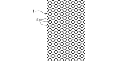
- the wire mesh f installed inside the louver e is an inexpensive expander in which a large number of meshes g are formed by forming horizontal cuts in a zigzag pattern on a metal plate and then spreading it vertically. Metal is used, and each mesh g has a flat rhombus shape as shown in FIG.
- an internal partition component that partitions an internal space near the air intake port of the duct body into a plurality of flow paths by a partition plate is incorporated in the duct body, and the partition plate
- the partition plate Although an example with a drip channel at the lower end is disclosed, this is intended for a type of intake duct that does not have a wire mesh inside the louver, and the drip channel shown here is from the air intake. It is for collecting the water droplets that have entered and collided with the partition plate, and it has been proposed that no countermeasure has been proposed for the water droplets flowing down the wire mesh inside the louver.
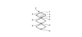
- the wire mesh f interposed inside the louver e of the air intake c c has a long side x (see FIG. 3) of the rhombus of each mesh g in the horizontal direction and is short. Since the side y (see FIG. 3) is vertical, the angle ⁇ of the lowest part of each mesh g becomes an obtuse angle, and the water droplets w that propagate through the wire mesh f tend to stay due to surface tension and stay here. As the water droplets w grow gradually and gradually, the air resistance gradually increases, and as a result, the water droplets w may be sucked deeply into the intake duct b when the water droplets w grow so large that the air resistance greatly increases. There was this.
- the present invention has been made in view of the above circumstances, and an object of the present invention is to provide an air intake duct that can reliably collect water droplets that have been aggregated and transferred by a wire mesh and prevent entry into the duct body.
- the present invention relates to an intake duct for taking outside air from an air intake as engine intake air, the duct main body having an outer shell structure with the air intake being opened upward, and the air intake covering the rain intake.
- a louver that prevents direct descending, and a wire mesh that is interposed inside the louver to prevent the suction of fine foreign matter, and the water droplets that flow down the wire mesh on the inner wall surface of the duct body directly below the air intake port A drip channel is formed to receive the water droplets, and the water droplets can be guided to a predetermined water recovery part in the duct body through the drip channel.
- the water droplets that aggregate and travel on the wire mesh are collected by the air. Since it is received by the drip channel directly under the inlet and guided to the predetermined water recovery section in the duct body through the drip channel and recovered, the water droplets are prevented from entering the duct body.
- the present invention further includes an internal partition component that is built in the duct body and divides an internal space near the air intake port of the duct body into a plurality of flow paths by a partition plate, and is provided immediately below the air intake port of the duct body. It is preferable to provide a drip channel forming portion for forming a drip channel between the inner wall surface and the inner partition part. In this way, it is only necessary to enclose the separately manufactured inner partition part at the time of blow molding of the duct body. A drip channel can be easily formed on the inner wall surface immediately below the air intake port of the duct body.
- the internal partition component when the internal partition component is provided in this way, it is preferable to equip the internal partition component side with a water recovery part that recovers water droplets guided by the drip channel. It is possible to easily provide a water recovery part in the duct body simply by enclosing the parts during blow molding of the duct body, and the water recovery part is defined by sandwiching and crushing a part of the duct body with a mold. It is possible to keep the flow path cross-sectional area large compared to the case of making it.
- a large number of meshes in the wire mesh are formed so as to form a rhombus whose long side is a vertical direction and whose short side is a horizontal direction.
- Each mesh of the wire mesh on the inside becomes a long and slender rhombus in the vertical direction, and the angle of the lowest part of each mesh becomes an acute angle, so that fine water droplets such as fog reach the wire mesh inside the louver with the flow of air.
- Even if the water drops, water droplets that aggregate and propagate in the wire mesh do not stay at the lowest part of each mesh and flow down without growing, and are received by the drip channel directly under the air intake, The water is guided to a predetermined water recovery unit and recovered.
- the wire mesh interposed inside the louver is made of expanded metal.
- the existing expanded metal is used in a direction different from the conventional one, so that the cost is low. Can be implemented.
- An internal partition component that divides an internal space that is built in the duct body and is close to the air intake port of the duct body into a plurality of flow paths by a partition plate, and an inner wall surface directly below the air intake port of the duct body If a drip channel forming part for forming a drip channel is provided in the internal partition part, the internal partition part manufactured separately is included just at the time of blow molding of the duct body, and immediately below the air inlet of the duct body. A drip channel can be easily formed on the inner wall surface of the casing, and the cost increase required for newly installing the drip channel can be remarkably suppressed.
- the duct body can be simply included when blow-molding the duct body. Since the water recovery part can be easily provided inside, the cross-sectional area of the flow path can be kept large compared to the case where the water recovery part is partitioned and made by sandwiching and crushing part of the duct body with a mold. Thus, a significant increase in intake resistance can be avoided in advance.
- the existing expanded metal can be used at a low cost by using it in a direction different from the conventional one, thereby significantly increasing the cost. It is possible to solve the problem that water droplets remain on each wire mesh without inviting.
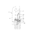
- FIGS. 4 to 6 show an example of an embodiment of the present invention.
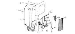
- An intake duct 1 in this embodiment is similar to the conventional intake duct b described in FIG. It is configured to take in outside air as intake air for the engine from an air intake 3 that extends in the vertical direction and is opened on the upper side thereof.
- a duct main body 4 that forms the following: a louver 5 that covers the air intake 3 to prevent direct rainwater from entering, and a wire mesh 6 that is interposed inside the louver 5 to prevent inhalation of fine foreign matter.
- a drip channel 7 (see FIGS. 5 and 6) is formed on the inner wall surface of the duct body 4 immediately below the air intake 3 to receive the water droplets w (see FIG. 5) that flow down the wire mesh 6, and the drip channel 7 To have said was configured to obtain lead the water droplets w to the water recovery unit 8 in the duct body 4 (see FIGS. 5 and 6).
- an internal partition component 12 that divides an internal space near the air intake port 3 of the duct body 4 into a plurality of flow paths by the partition plates 9, 10, 11 is incorporated in the duct body 4,
- the angle-type drip channel forming part 13 (see FIG. 4) provided on the internal partition part 12 side is provided with the duct body 4.
- the drip channel 7 (see FIG. 5) is formed between the inner wall surface by abutting and integrating with the inner wall surface immediately below the air intake 3 in the water intake section 8. It is provided in a part on the inner partition part 12 side and is integrated with the inner wall surface of the duct body 4 when the duct body 4 is blow-molded.
- Two of the three partition plates 9, 10, 11 provided in the internal partition component 12 are air intakes. It forms a surface facing the inlet 3 and is arranged at an interval on the front side and the rear side, and the upper side is curved toward the air inlet 3 side so that the air inlet 3 is divided into three parts vertically.
- the remaining one partition plate 11 is perpendicular to each other between the partition plates 9 and 10 so as to divide the flow path sandwiched between the two partition plates 9 and 10 into left and right parts.
- the three partition plates 9, 10, 11 divide the internal space of the duct body 4 near the air inlet 3 into four flow paths.
- the three partition plates 9, 10, 11 are fitted into the inner wall surface of the duct body 4 over the entire circumference in the middle part in the vertical direction of the two partition plates 9, 10, and the three partition plates 9, 10, 11 are connected to the duct body
- a support frame 14 for supporting from the side 4 is formed, but the support frame 14 itself is a similar drip channel forming part including the drip channel forming part 13 as a part, and the air intake 3 A drip channel is formed over the entire circumference including the drip channel 7 directly below.
- the support frame 14 is provided with the above-described water recovery portion 8 (see FIG. 5) so as to recover the water droplets w received by the drip channel (including the drip channel 7) over the entire circumference thereof.
- the support frame 14 is provided with a downward slope so that the water droplets w can flow down toward the water recovery unit 8, and the surfaces of the two partition plates 9 and 10 correspond to the support frame 14.
- the drip channels 15 and 16 are formed at a height position where the drip channels 15 and 16 are formed, and a downward gradient is given to the water recovery unit 8.
- a drainage port (not shown) that penetrates the duct body 4 and opens to the outside is provided by post-processing at the bottom of the water recovery unit 8 so that water can be drained from the drainage port. It is preferable to keep it.
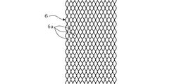
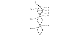
- a large number of meshes 6a in the wire mesh 6 form a rhombus having a long side x as a vertical direction and a short side y as a horizontal direction.
- a metal mesh 6 is made of expanded metal, and the existing expanded metal has a direction different from the conventional one (the conventional direction in which the rhombus of the mesh 6a is elongated in the horizontal direction).
- the wire mesh 6 is configured by using 90 ° rotation in a direction in which the rhombuses of the mesh 6a are elongated in the vertical direction.
- the intake duct 1 is configured in this way, even if fine water droplets w such as fog reach the wire mesh 6 inside the louver 5 along with the flow of air, the wire mesh 6
- the water droplets w that aggregate and flow down are received by the drip channel 7 immediately below the air intake 3 and are guided to the water recovery unit 8 through the drip channel 7 and recovered, so that the water droplets w enter the duct body 4. Intrusion is prevented.
- this type of air intake duct 1 is manufactured by blow molding. At this time, the internal partition part 12 manufactured separately is included only when the duct body 4 is blow molded. The drip channel 7 can be easily formed on the inner wall surface immediately below the air intake 3 of the duct body 4.
- the inner partition part 12 is simply included when the duct body 4 is blow molded. It is possible to easily provide the water recovery unit 8 in the duct body 4 and cut off the flow path as compared with the case where the water recovery unit is partitioned by crushing a part of the duct body 4 with a mold. The area can be kept large.
- each mesh 6a of the metal mesh 6 inside the louver 5 becomes a long and slender rhombus in the vertical direction
- the angle ⁇ (see FIG. 8) of the lowest part of each mesh 6a becomes an acute angle. 8) reaches the wire mesh 6 inside the louver 5 along with the flow of air, the water droplets w that aggregate and travel on the wire mesh 6 do not stay at the lowest part of each mesh 6a. Then, the water flows down without being grown and is received by the drip channel 7 immediately below the air intake 3 and is guided to the water recovery unit 8 through the drip channel 7 and recovered.
- the water droplets w aggregated and carried by the wire mesh 6 are received by the drip channel 7 directly below the air intake 3 and guided to the water recovery unit 8 through the drip channel 7 to be reliably recovered. Therefore, entry of water droplets w into the duct body 4 can be prevented.
- the drip channel 7 can be easily formed on the inner wall surface immediately below the air intake 3 of the duct body 4 simply by enclosing the separately produced internal partition part 12 when the duct body 4 is blow-molded. It is possible to remarkably suppress an increase in cost required for newly establishing the channel 7.
- the water recovery part 8 can be easily provided in the duct body 4 simply by enclosing the separately produced internal partition part 12 when the duct body 4 is blow-molded.
- the cross-sectional area of the flow path can be kept large compared with the case where the water recovery unit 8 is divided and made by sandwiching and crushing at, and a significant increase in intake resistance can be avoided in advance.
- the intake duct 1 can be reliably prevented, and the air / water separation efficiency is higher than the conventional one.
- the metal mesh 6 interposed inside the louver 5 is made of expanded metal, it can be implemented at a low cost by using the existing expanded metal in a direction different from the conventional one. As a result, it is possible to solve the problem of water droplets w remaining on each mesh 6a of the wire mesh 6 without causing a significant increase in cost.
- the air intake duct of the present invention is not limited to the above-described embodiment, and the drip channel and the water recovery portion directly below the air intake port are not necessarily limited to being formed using internal partition parts.
- the wire mesh is not necessarily limited to being composed of expanded metal, and various modifications can be made without departing from the scope of the present invention.
Landscapes
- Engineering & Computer Science (AREA)
- Chemical & Material Sciences (AREA)
- Combustion & Propulsion (AREA)
- Mechanical Engineering (AREA)
- General Engineering & Computer Science (AREA)
- Exhaust Silencers (AREA)
- Cooling, Air Intake And Gas Exhaust, And Fuel Tank Arrangements In Propulsion Units (AREA)
Abstract
La présente invention concerne un conduit d'admission d'air (1) pour véhicules. Le conduit d'admission d'air (1) comprend : un corps de conduit (4) ayant une ouverture d'admission d'air (3) qui est ouverte sur le côté supérieur du corps de conduit (4) et comprenant une structure de coque externe ; un évent à lames (5) pour recouvrir l'ouverture d'admission d'air (3) afin d'empêcher l'entrée directe d'eau de pluie ; et un treillis métallique (6) disposé à l'intérieur de l'évent à lames (5) et empêchant les matières étrangères d'être aspirées vers l'intérieur. Le conduit d'admission d'air (1) est conçu de sorte que : un canal de récupération (7) pour récupérer des gouttelettes d'eau (w) circulant vers le bas le long du treillis métallique (6) soit formé sur une surface de paroi interne du corps de conduit (4), la surface de paroi interne étant située directement sous l'ouverture d'admission d'air (3), et que les gouttelettes d'eau (w) puissent être conduites vers une section de récupération d'eau prédéfinie (8) au sein du corps de conduit (4) par le biais du canal de récupération (7).
Priority Applications (1)
| Application Number | Priority Date | Filing Date | Title |
|---|---|---|---|
| CN201780024839.0A CN109072830A (zh) | 2016-04-19 | 2017-02-15 | 吸气管道 |
Applications Claiming Priority (4)
| Application Number | Priority Date | Filing Date | Title |
|---|---|---|---|
| JP2016-083524 | 2016-04-19 | ||
| JP2016-083432 | 2016-04-19 | ||
| JP2016083432A JP6626775B2 (ja) | 2016-04-19 | 2016-04-19 | 吸気ダクト |
| JP2016083524A JP6641225B2 (ja) | 2016-04-19 | 2016-04-19 | 吸気ダクト |
Publications (1)
| Publication Number | Publication Date |
|---|---|
| WO2017183269A1 true WO2017183269A1 (fr) | 2017-10-26 |
Family
ID=60116708
Family Applications (1)
| Application Number | Title | Priority Date | Filing Date |
|---|---|---|---|
| PCT/JP2017/005406 Ceased WO2017183269A1 (fr) | 2016-04-19 | 2017-02-15 | Conduit d'admission d'air |
Country Status (2)
| Country | Link |
|---|---|
| CN (1) | CN109072830A (fr) |
| WO (1) | WO2017183269A1 (fr) |
Cited By (4)
| Publication number | Priority date | Publication date | Assignee | Title |
|---|---|---|---|---|
| EP3378690A4 (fr) * | 2015-11-19 | 2019-06-19 | Hino Motors Ltd. | Conduit d'admission d'air |
| US11181081B2 (en) * | 2019-10-16 | 2021-11-23 | Deere & Company | Air intake for work vehicle |
| USD966343S1 (en) | 2019-10-16 | 2022-10-11 | Deere & Company | Air intake tower |
| USD967199S1 (en) | 2019-10-16 | 2022-10-18 | Deere & Company | Air intake tower |
Citations (8)
| Publication number | Priority date | Publication date | Assignee | Title |
|---|---|---|---|---|
| JPH045119U (fr) * | 1990-04-27 | 1992-01-17 | ||
| JPH0532765U (ja) * | 1991-10-07 | 1993-04-30 | 日野自動車工業株式会社 | スタツクインテークダクト |
| JPH08230491A (ja) * | 1995-02-28 | 1996-09-10 | Kyoraku Co Ltd | 車両用エアインテークダクト |
| JP2000320414A (ja) * | 1999-05-12 | 2000-11-21 | Hino Motors Ltd | 吸気ダクト |
| JP2000320412A (ja) * | 1999-05-07 | 2000-11-21 | Hino Motors Ltd | 吸気水切りチャンバ |
| JP2007181762A (ja) * | 2006-01-06 | 2007-07-19 | Wako Filter Technology Kk | フィルタエレメントの取付構造 |
| US20090101014A1 (en) * | 2007-06-20 | 2009-04-23 | Michel Baseotto | Moisture separator arrangement; fluid intake for air cleaner; and,method |
| WO2011094334A1 (fr) * | 2010-01-29 | 2011-08-04 | Donaldson Company, Inc. | Ensemble séparateur d'eau destiné à être utilisé avec des épurateurs d'air, ensemble, éléments, systèmes et procédés associés |
Family Cites Families (5)
| Publication number | Priority date | Publication date | Assignee | Title |
|---|---|---|---|---|
| JP5325764B2 (ja) * | 2009-12-25 | 2013-10-23 | 日野自動車株式会社 | 吸気ダクト及びその製造方法 |
| CN201826990U (zh) * | 2010-09-28 | 2011-05-11 | 北汽福田汽车股份有限公司 | 发动机用进气装置及其车辆 |
| CN202108622U (zh) * | 2011-04-18 | 2012-01-11 | 南充市攀峰滤清器有限公司 | 重型汽车组合式排水预滤进气管 |
| US9151253B2 (en) * | 2012-11-30 | 2015-10-06 | Cnh Industrial America Llc | Rain deflector for an intake duct of a work vehicle |
| CN102996298B (zh) * | 2012-12-11 | 2015-01-14 | 山东统亚模塑科技实业有限公司 | 具有二次排水的高位进气管 |
-
2017
- 2017-02-15 CN CN201780024839.0A patent/CN109072830A/zh active Pending
- 2017-02-15 WO PCT/JP2017/005406 patent/WO2017183269A1/fr not_active Ceased
Patent Citations (8)
| Publication number | Priority date | Publication date | Assignee | Title |
|---|---|---|---|---|
| JPH045119U (fr) * | 1990-04-27 | 1992-01-17 | ||
| JPH0532765U (ja) * | 1991-10-07 | 1993-04-30 | 日野自動車工業株式会社 | スタツクインテークダクト |
| JPH08230491A (ja) * | 1995-02-28 | 1996-09-10 | Kyoraku Co Ltd | 車両用エアインテークダクト |
| JP2000320412A (ja) * | 1999-05-07 | 2000-11-21 | Hino Motors Ltd | 吸気水切りチャンバ |
| JP2000320414A (ja) * | 1999-05-12 | 2000-11-21 | Hino Motors Ltd | 吸気ダクト |
| JP2007181762A (ja) * | 2006-01-06 | 2007-07-19 | Wako Filter Technology Kk | フィルタエレメントの取付構造 |
| US20090101014A1 (en) * | 2007-06-20 | 2009-04-23 | Michel Baseotto | Moisture separator arrangement; fluid intake for air cleaner; and,method |
| WO2011094334A1 (fr) * | 2010-01-29 | 2011-08-04 | Donaldson Company, Inc. | Ensemble séparateur d'eau destiné à être utilisé avec des épurateurs d'air, ensemble, éléments, systèmes et procédés associés |
Cited By (10)
| Publication number | Priority date | Publication date | Assignee | Title |
|---|---|---|---|---|
| EP3378690A4 (fr) * | 2015-11-19 | 2019-06-19 | Hino Motors Ltd. | Conduit d'admission d'air |
| US10690095B2 (en) | 2015-11-19 | 2020-06-23 | Hino Motors, Ltd. | Air intake duct |
| US11181081B2 (en) * | 2019-10-16 | 2021-11-23 | Deere & Company | Air intake for work vehicle |
| USD966343S1 (en) | 2019-10-16 | 2022-10-11 | Deere & Company | Air intake tower |
| USD967199S1 (en) | 2019-10-16 | 2022-10-18 | Deere & Company | Air intake tower |
| USD993992S1 (en) | 2019-10-16 | 2023-08-01 | Deere & Company | Air intake tower |
| USD993991S1 (en) | 2019-10-16 | 2023-08-01 | Deere & Company | Air intake tower |
| USD1048103S1 (en) | 2019-10-16 | 2024-10-22 | Deere & Company | Air intake tower |
| USD1056968S1 (en) | 2019-10-16 | 2025-01-07 | Deere & Company | Air intake tower |
| USD1078803S1 (en) | 2019-10-16 | 2025-06-10 | Deere & Company | Air intake tower |
Also Published As
| Publication number | Publication date |
|---|---|
| CN109072830A (zh) | 2018-12-21 |
Similar Documents
| Publication | Publication Date | Title |
|---|---|---|
| EP2611638A1 (fr) | Admission d'air au-dessus du tablier pour absorption réduite de neige | |
| JP2014512293A (ja) | オーバーバルクヘッド吸気システム | |
| US10035405B2 (en) | Louvered rain-hat for the fresh air inlet of a vehicle | |
| CN107531289B (zh) | 用于机动车的导风盖板布置结构 | |
| JP3954754B2 (ja) | 吸気ダクト | |
| WO2017086261A1 (fr) | Conduit d'admission d'air | |
| CN107628121A (zh) | 发动机室组件和车辆 | |
| JP6594173B2 (ja) | 吸気ダクト | |
| CN211494255U (zh) | 用于车辆的通风盖板总成、前围组件和车辆 | |
| JP5169971B2 (ja) | エンジンの吸気構造 | |
| CN109072830A (zh) | 吸气管道 | |
| CN217532758U (zh) | 一种车辆的前舱导水结构及车辆 | |
| CN109072829A (zh) | 吸气管道 | |
| CN203670043U (zh) | 一种车用进气结构、车用进气系统及相应的汽车 | |
| CN103452711B (zh) | 一种汽车空滤器进气结构 | |
| CN104727995B (zh) | 一种车用进气结构、车用进气系统及相应的汽车 | |
| JP2017194031A (ja) | 吸気ダクト | |
| CN108798948B (zh) | 一种车辆进气装置 | |
| JP5485685B2 (ja) | 吸気ダクト | |
| JP2017193215A (ja) | 吸気ダクト | |
| JP5071781B2 (ja) | 車両前部形状 | |
| JP6626776B2 (ja) | 吸気ダクト | |
| CN114954277A (zh) | 一种通风盖板及车辆 | |
| JP2002295323A (ja) | 自動二輪車の吸気構造 | |
| JP2000168374A (ja) | エアーインテークダクト構造 |
Legal Events
| Date | Code | Title | Description |
|---|---|---|---|
| NENP | Non-entry into the national phase |
Ref country code: DE |
|
| 121 | Ep: the epo has been informed by wipo that ep was designated in this application |
Ref document number: 17785614 Country of ref document: EP Kind code of ref document: A1 |
|
| 122 | Ep: pct application non-entry in european phase |
Ref document number: 17785614 Country of ref document: EP Kind code of ref document: A1 |