WO2017183293A1 - Dispositif d'amplification de différence de phase - Google Patents
Dispositif d'amplification de différence de phase Download PDFInfo
- Publication number
- WO2017183293A1 WO2017183293A1 PCT/JP2017/006942 JP2017006942W WO2017183293A1 WO 2017183293 A1 WO2017183293 A1 WO 2017183293A1 JP 2017006942 W JP2017006942 W JP 2017006942W WO 2017183293 A1 WO2017183293 A1 WO 2017183293A1
- Authority
- WO
- WIPO (PCT)
- Prior art keywords
- user
- image
- robot
- hmd
- image data
- Prior art date
- Legal status (The legal status is an assumption and is not a legal conclusion. Google has not performed a legal analysis and makes no representation as to the accuracy of the status listed.)
- Ceased
Links
Images


Classifications
-
- G—PHYSICS
- G02—OPTICS
- G02B—OPTICAL ELEMENTS, SYSTEMS OR APPARATUS
- G02B27/00—Optical systems or apparatus not provided for by any of the groups G02B1/00 - G02B26/00, G02B30/00
- G02B27/02—Viewing or reading apparatus
-
- H—ELECTRICITY
- H04—ELECTRIC COMMUNICATION TECHNIQUE
- H04R—LOUDSPEAKERS, MICROPHONES, GRAMOPHONE PICK-UPS OR LIKE ACOUSTIC ELECTROMECHANICAL TRANSDUCERS; ELECTRIC HEARING AIDS; PUBLIC ADDRESS SYSTEMS
- H04R1/00—Details of transducers, loudspeakers or microphones
- H04R1/20—Arrangements for obtaining desired frequency or directional characteristics
- H04R1/32—Arrangements for obtaining desired frequency or directional characteristics for obtaining desired directional characteristic only
- H04R1/40—Arrangements for obtaining desired frequency or directional characteristics for obtaining desired directional characteristic only by combining a number of identical transducers
-
- H—ELECTRICITY
- H04—ELECTRIC COMMUNICATION TECHNIQUE
- H04R—LOUDSPEAKERS, MICROPHONES, GRAMOPHONE PICK-UPS OR LIKE ACOUSTIC ELECTROMECHANICAL TRANSDUCERS; ELECTRIC HEARING AIDS; PUBLIC ADDRESS SYSTEMS
- H04R3/00—Circuits for transducers
Definitions
- the present invention relates to a technique for moving a robot according to a user's movement and using viewing data generated by the robot.
- Head mounted display is used in various fields. By providing the HMD with a head tracking function and updating the display screen in conjunction with the posture of the user's head, a sense of immersion in the video world can be enhanced.
- a remote robot sends surrounding image data and audio data to the user and reproduces it on the user side, so that the user can communicate with the surrounding people with a sense of presence like being in the robot's location. It becomes possible.
- the present inventor has paid attention to the possibility of the cooperation between the telexistence and the HMD, and has developed a technology for improving the convenience and usefulness of the telejeg resistance system.
- the present invention has been made in view of these problems, and its purpose is to make effective use of the structure of a remotely operated robot, technology for processing viewing data acquired by the robot, and viewing data acquired by the robot. Is to provide the technology.
- a phase difference amplifying device includes a first microphone that generates a first audio signal, a first positive-phase signal obtained by amplifying the first audio signal, and a first audio signal.
- a first amplifier that outputs a first antiphase signal obtained by inverting and amplifying the signal, a second microphone that is arranged at a position different from the first microphone and that generates a second audio signal, and a second amplifier that amplifies the second audio signal.
- a second amplifier that outputs a normal phase signal and a second negative phase signal obtained by inverting and amplifying the second audio signal; a signal obtained by multiplying the first positive phase signal by a first coefficient; and a second negative phase signal that is a second coefficient.
- any combination of the above components, the expression of the present invention converted between a method, an apparatus, a system, a computer program, a recording medium on which the computer program is recorded so as to be readable, a data structure, and the like are also included in the present invention. It is effective as an embodiment of
- FIG. 1 shows a configuration example of an information processing system 1 in the embodiment.
- the information processing system 1 includes a robot 10 and a head mounted display device (HMD) 100 that a user A wears on the head.
- the HMD 100 includes a display panel 102 for both eyes, an earphone 104 for both ears, and a microphone 106.
- the earphone 104 is used as the sound output means, but a headphone shaped to touch the ear may be used.
- the HMD 100 is connected to the network 4 via an access point (AP) 2.
- the AP 2 has functions of a wireless access point and a router, and the HMD 100 is connected to the AP 2 by a known wireless communication protocol, but may be connected by a cable.
- the robot 10 includes an actuator device 12 and a housing 20 that is driven by the actuator device 12 so that the posture can be changed.
- the housing 20 is equipped with a right camera 14a, a left camera 14b, a right microphone 16a, a left microphone 16b, and a speaker 18.
- the right camera 14a and the left camera 14b will be referred to as “camera 14” unless otherwise distinguished, and the right microphone 16a and the left microphone 16b will be referred to as “mic 16” unless otherwise distinguished.
- the camera 14 and the microphone 16 are provided in the housing 20 driven by the actuator device 12, but the speaker 18 may be provided in the hemispherical housing 36 of the actuator device 12, for example.
- the robot 10 is connected to the network 4 via an access point (AP) 3.
- the robot 10 is connected to the AP 3 by a known wireless communication protocol, but may be connected by a cable.
- the HMD 100 and the robot 10 are communicably connected via the network 4.
- the HMD 100 and the robot 10 may be connected to each other so as to be able to communicate directly or wirelessly without using an AP.
- the robot 10 operates as a so-called alternate user A.
- the movement of the HMD 100 worn by the user A is transmitted to the robot 10, and the actuator device 12 moves the housing 20 in conjunction with the movement of the HMD 100.
- the actuator device 12 moves the casing 20 to swing back and forth
- the actuator device 12 moves the casing 20 to swing left and right.
- a person around the robot 10 can communicate with the user A with a sense that the user A is on the spot.
- the right camera 14a and the left camera 14b are arranged at a predetermined interval in the horizontal direction on the front surface of the housing 20.
- the right camera 14a and the left camera 14b constitute a stereo camera.
- the right camera 14a captures a right-eye image at a predetermined cycle
- the left camera 14b captures a left-eye image at a predetermined cycle.
- the captured right-eye image and left-eye image are transmitted to the user A's HMD 100 in real time.
- the HMD 100 displays the received right-eye image on the right-eye display panel, and displays the received left-eye image on the left-eye display panel.
- the user A can view the video in the direction in which the housing 20 of the robot 10 is facing in real time.
- the right microphone 16a and the left microphone 16b are arranged in the housing 20 with a predetermined interval in the lateral direction.
- the right microphone 16a and the left microphone 16b constitute a stereo microphone, and are arranged at a predetermined interval in the horizontal direction, so that the time for the sound to reach varies depending on the position of the sound source.
- the difference in the arrival time of sound appears as a phase difference between sound signals generated by the right microphone 16a and the left microphone 16b.
- the right microphone 16a and the left microphone 16b may be arranged as far apart as possible, specifically on both sides of the housing 20. preferable.
- the audio signals generated by the right microphone 16a and the left microphone 16b are processed as will be described later, and are transmitted to the user A's HMD 100 in real time as audio data for the right ear and audio data for the left ear.
- the HMD 100 outputs the received right ear audio data from the right ear earphone 104, and outputs the received left ear audio data from the left ear earphone 104. Thereby, the user A can hear the sound around the robot 10 in real time.
- the front surface of the housing 20 has a flat shape, and the microphone 16 does not have a shape corresponding to an auricle or an external auditory canal, so the difference in sound arrival time is substantially the difference between the sound source and both microphones. It will correspond to.
- the right microphone 16a and the left microphone 16b are arranged on both side surfaces of the housing 20 and are provided at positions farthest from each other. However, the sound signal generated by the right microphone 16a and the left microphone 16b are generated. The inventor's experiment has revealed that even if the audio signal is amplified and output from the right earphone and the left earphone, the position of the sound source in the left-right direction cannot be perceived well.
- the robot 10 has a mechanism for amplifying the phase difference between the audio signals of the right microphone 16a and the left microphone 16b and providing the HMD 100 with audio data that is closer to the sound that can be heard by both human ears. This mechanism will be described later.
- the microphone 106 generates an audio signal emitted by the user A.
- the voice data by the user A is transmitted to the robot 10 in real time, and the robot 10 outputs the received voice data from the speaker 18. Thereby, the person around the robot 10 can hear the voice uttered by the user A in real time.
- the robot 10 is remotely operated by the user A to reproduce the movement and sound of the face of the user A, and the user A can view images and sounds around the robot through the HMD 100. And people around the robot 10 can communicate in real time.
- Such an information processing system 1 is usefully used in various environments.
- FIG. 2 shows an example of the usage scene of the robot 10.
- a meeting is held in a room, and a robot 10 that is a user A's alternate is placed on a table.
- the robot 10 faces the front four people, and the camera 14 photographs the front four people within the angle of view.
- the robot 10 transmits the captured image of the camera 14 to the user A's HMD 100 in real time.
- the user A participates in the conference while viewing the room status through the display panel 102 of the HMD 100 and speaks to transmit the voice of the user A to the robot 10 in real time, and the robot 10 outputs the voice of the user A from the speaker 18.
- the robot 10 transmits the audio data obtained by amplifying the phase difference between the audio signals generated by the left and right microphones 16 to the HMD 100 in real time.
- the user A can perceive whether the person who has spoken in the room is located on the right side, the left side, or the front side with respect to the direction in which the housing 20 is facing.
- the user A feels that the person on the right side speaks, the user A turns the neck to the right and turns to the right side.
- the housing 20 of the robot 10 since the housing 20 of the robot 10 also faces the right side in conjunction with the movement of the neck of the user A, the camera 14 photographs the participant sitting on the right side.
- the user A can join the conference as if he was in a room while being at a remote place by having the alternate robot 10 interlocked with the movement of the user A.
- participants who are actually in the room can communicate with the user A from the voice of the user A and the movement of the housing 20 without feeling uncomfortable.
- the usage scene shown in FIG. 2 is an example, and the user A can obtain viewing data from the robot 10 while in a remote location even in other usage scenes.
- FIG. 3 shows an example of the external shape of the HMD 100.
- the HMD 100 includes an output mechanism unit 110 and a mounting mechanism unit 112.
- the wearing mechanism unit 112 includes a wearing band 108 that goes around the head when worn by the user and fixes the HMD 100 to the head.
- the wearing band 108 is made of a material or a structure whose length can be adjusted according to the user's head circumference.
- the output mechanism unit 110 includes a casing 114 shaped to cover the left and right eyes when the user wears the HMD 100, and includes a display panel 102 in a position facing the eyes.
- the display panel 102 may be a liquid crystal panel or an organic EL panel.
- the HMD 100 further includes an earphone 104 that is inserted into the user's ear when worn.
- the earphone 104 is an example of an audio output unit, and the HMD 100 may include a headphone.
- the HMD 100 and the headphones may be configured integrally, but may be separate.
- the HMD 100 transmits the sensor information detected by the posture sensor and the voice data obtained by encoding the voice signal from the microphone 106 to the robot 10 and receives the image data and voice data generated by the robot 10 to display the display panel. 102 and the earphone 104.
- the HMD 100 shown in FIG. 3 is an immersive (non-transmissive) display device that completely covers both eyes, but may be a transmissive display device.
- the shape may be a hat shape as shown in the figure, but may also be a glasses shape.
- the HMD 100 may include not only a dedicated head-mounted display device but also a terminal device having a display panel, a microphone, and a speaker, and a housing that fixes the display panel of the terminal device to a position in front of the user's eyes.
- the terminal device may have a relatively small display panel such as a smartphone or a portable game machine.
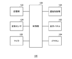
- FIG. 4 shows functional blocks of the HMD 100.
- the control unit 120 is a main processor that processes and outputs various signals and data such as image signals, audio signals, sensor information, and commands.
- the storage unit 122 temporarily stores data, commands, and the like that are processed by the control unit 120.
- the attitude sensor 124 detects attitude information such as the rotation angle and inclination of the HMD 100 at a predetermined cycle.
- the posture sensor 124 includes at least a triaxial acceleration sensor and a triaxial gyro sensor.
- the microphone 106 converts a user's voice into an electrical signal and generates an audio signal.
- the communication control unit 126 transmits and receives signals and data to and from the robot 10 by wired or wireless communication via a network adapter or an antenna.
- the communication control unit 126 receives, from the control unit 120, the posture information detected by the posture sensor 124 and the voice data obtained by encoding the voice signal from the microphone 106, and transmits them to the robot 10.
- the communication control unit 126 receives image data and audio data from the robot 10 and supplies them to the control unit 120.
- the control unit 120 Upon receiving image data and audio data from the robot 10, the control unit 120 supplies the image data to the display panel 102 for display, and supplies the audio data to the earphone 104 for audio output.
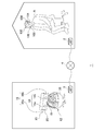
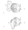
- FIG. 5 shows an external configuration of the robot 10.
- the housing 20 accommodates the camera 14, the microphone 16, and the speaker 18.
- the camera 14 and the speaker 18 are provided on the front surface of the housing, and the microphone 16 is provided on the side surface of the housing.
- the camera 14, the microphone 16, and the speaker 18 operate by being supplied with electric power from a power supply device housed in the housing 36 via a power line (not shown).
- the housing 20 has a protective cover 19.
- the protective cover 19 When the robot 10 is not used, that is, when the power of the robot 10 is turned off, the protective cover 19 is disposed at a closed position that covers the front of the housing, and the camera 14 and The speaker 18 is protected.
- the protective cover 19 has a rotation shaft projecting inward at both ends in the longitudinal direction, and is attached by inserting each rotation shaft into a pair of shaft holes on the side surface of the housing.
- the protective cover 19 is attached to the housing 20 so as to be rotatable about the rotation axis.
- the protective cover 19 In the state shown in FIG. 5, the protective cover 19 is disposed at the open position rotated approximately 180 degrees from the closed position, and the camera 14 is exposed so that the surroundings can be photographed.
- the protective cover 19 preferably has a stopper mechanism that is fixed in the open position.
- the protective cover 19 may be driven and controlled according to the emotion of the user wearing the HMD 100 and the tilt of the neck.
- a motor as a drive unit is provided in the housing 20, and the operation of the protective cover 19 can be controlled by connecting the motor shaft to the rotating shaft of the protective cover 19.
- the stopper mechanism is not provided, and the protective cover 19 may be rotatable within a range of approximately 270 degrees from the closed position.
- the housing 20 is supported by the actuator device 12 so that the posture can be changed.
- the actuator device 12 includes a leg portion 40, a hemispherical housing 36 supported on the upper portion of the leg portion 40, and a drive mechanism 50 for driving the housing 20.
- the drive mechanism 50 includes a first arcuate arm 32 having a first through hole 32a formed in the longitudinal direction, a second arcuate arm 34 having a second through hole 34a formed in the longitudinal direction, A pedestal 30 that rotatably supports the first arc-shaped arm 32 and the second arc-shaped arm 34 in a state where the first arc-shaped arm 32 and the second arc-shaped arm 34 intersect each other is provided.
- the upper side of the pedestal 30 is covered with a cover 38, and motors for rotating the first arcuate arm 32 and the second arcuate arm 34 are arranged in the space covered with the cover 38, respectively.
- the pedestal 30 is rotatably supported with respect to the housing 36, and a motor for rotating the pedestal 30 is disposed in the housing 36.
- the first arc-shaped arm 32 and the second arc-shaped arm 34 are formed in a semicircular shape, and both ends are supported by the pedestal 30 so as to have the same center of rotation.
- the diameter of the semicircular first arc-shaped arm 32 is slightly larger than the diameter of the semicircular second arc-shaped arm 34, and the first arc-shaped arm 32 is located on the outer peripheral side of the second arc-shaped arm 34. Be placed.
- the first arc-shaped arm 32 and the second arc-shaped arm 34 may be arranged so as to be orthogonal to each other on the pedestal 30.
- a line connecting both ends of the first arcuate arm 32 supported by the pedestal 30 and a line connecting both ends of the second arcuate arm 34 supported by the pedestal 30 are orthogonal to each other.
- the insertion member 42 is inserted into the first through long hole 32a and the second through long hole 34a, and is disposed at the intersection of the first through long hole 32a and the second through long hole 34a.
- the insertion member 42 slides in the first through long hole 32a and the second through long hole 34a by the rotation of the first arc-shaped arm 32 and the second arc-shaped arm 34.
- FIG. 6 shows the configuration of the insertion member 42.
- the insertion member 42 has a first restriction portion 42a wider than the first through long hole 32a and the second through long hole 34a so as to maintain the insertion state of the first through long hole 32a and the second through long hole 34a. And a wider second restricting portion 42b.
- the first restricting portion 42a is disposed above the first through long hole 32a
- the second restricting portion 42b is disposed below the second through long hole 34a
- the insertion member 42 is the first through long hole 32a. Further, it is prevented from dropping off from the second through long hole 34a.
- first restricting portion 42a or the second restricting portion 42b is formed separately from the shaft portion 42c, and the shaft A structure may be adopted in which the portion 42c is fixed to the end portion of the shaft portion 42c in a state where the portion 42c is inserted into the first through long hole 32a and the second through long hole 34a.
- the shaft portion 42c is a portion inserted into the first through long hole 32a and the second through long hole 34a, and is always located at the intersection of the first through long hole 32a and the second through long hole 34a.
- the rotation of the shaft portion 42c is restricted in the first through long hole 32a and the second through long hole 34a.
- the shaft portion 42c has a rectangular cross section having a width slightly narrower than the widths of the first through long hole 32a and the second through long hole 34a, and the inside of the first through long hole 32a and the second through long hole Although the rotation is restricted within 34a, the rotation of the shaft portion 42c may be restricted by other means.
- a rail is provided on the inner peripheral surface of the second arc-shaped arm 34, a rail groove is provided in the second restricting portion 42b, and the rotation of the shaft portion 42c is restricted by fitting the rail and the rail groove. Also good.
- the housing 20 is attached to the first restricting portion 42a, and the rotation of the shaft portion 42c is restricted, so that the housing 20 can be maintained in a desired posture.
- the shaft portion 42c has a narrower width than the first through long hole 32a and the second through long hole 34a, so that it can slide in the first through long hole 32a and the second through long hole 34a. To do. Accordingly, the insertion member 42 can move along the first through long hole 32a and can move along the second through long hole 34a by the rotation of the first circular arc arm 32 and the second circular arc arm 34.
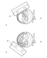
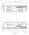
- FIG. 7 shows a cross section of the robot 10.
- FIG. 7 mainly shows a drive system of the robot 10, and illustration of a control circuit board, a memory, wiring, and the like is omitted.
- FIG. 7A shows a cross section cut along the second arcuate arm 34 in a state where the first arcuate arm 32 and the second arcuate arm 34 stand 90 degrees with respect to the pedestal 30.
- (B) shows a cross-section cut along the first arc-shaped arm 32 in a state where the first arc-shaped arm 32 and the second arc-shaped arm 34 stand 90 degrees with respect to the pedestal 30.
- the first motor 52 is provided for rotating the first arcuate arm 32
- the second motor 54 is provided for rotating the second arcuate arm 34.
- the first motor 52 and the second motor 54 are arranged on the pedestal 30, and when the pedestal 30 rotates, the first motor 52 and the second motor 54 also rotate together with the pedestal 30.
- the third motor 56 is provided to rotate the pedestal 30 and is disposed in the housing 36. The first motor 52, the second motor 54, and the third motor 56 are rotated by power supplied from a power supply device (not shown).
- the first motor 52 rotates the first arc-shaped arm 32
- the second motor 54 rotates the second arc-shaped arm 34
- the third motor 56 rotates the pedestal 30.
- the orientation and posture of the housing 20 attached to 42 can be changed.
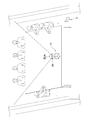
- FIGS. 8 and 9 are diagrams illustrating examples of the posture of the housing 20 in the robot 10.
- 8A and 8B show an example in which the housing 20 is tilted in the left-right direction.
- FIGS. 9A and 9B show an example in which the housing 20 is tilted in the front-rear direction.
- the drive mechanism 50 of the robot 10 can cause the housing 20 to take an arbitrary posture.
- the attitude of the housing 20 is controlled by adjusting the driving amounts of the first motor 52 and the second motor 54, and the orientation of the housing 20 is controlled by adjusting the driving amount of the third motor 56. .
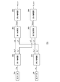
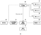
- FIG. 10 shows functional blocks of the robot 10.
- the robot 10 includes an input system 22 that receives and processes input from the outside, and an output system 24 that processes output to the outside.
- the input system 22 includes a reception unit 60, a sensor information acquisition unit 62, a motion detection unit 64, a line-of-sight direction determination unit 66, an actuator control unit 68, an audio data acquisition unit 70, and an audio processing unit 72.
- the output system 24 includes an image processing unit 80, an audio processing unit 82, and a transmission unit 90.
- each element described as a functional block for performing various processes can be configured by a circuit block, a memory, and other LSIs in terms of hardware, and loaded in the memory in terms of software. Realized by programs. Therefore, it is understood by those skilled in the art that these functional blocks can be realized in various forms by hardware only, software only, or a combination thereof, and is not limited to any one.
- the HMD 100 transmits the sensor information detected by the posture sensor 124 and the voice data obtained by encoding the voice signal generated by the microphone 106 to the robot 10, and the receiving unit 60 receives the sensor information and the voice data.
- the audio data acquisition unit 70 acquires the received audio data
- the audio processing unit 72 performs audio processing, and outputs it from the speaker 18.
- the robot 10 reproduces the voice of the user A in real time, and the people around the robot 10 can hear the voice of the user A.
- the sensor information acquisition unit 62 acquires the posture information detected by the posture sensor 124 of the HMD 100.
- the motion detection unit 64 detects the posture of the HMD 100 attached to the user A's head.
- the line-of-sight direction determination unit 66 determines the line-of-sight direction of the camera 14 of the housing 20 according to the attitude of the HMD 100 detected by the motion detection unit 64.
- the motion detection unit 64 performs a head tracking process for detecting the posture of the head of the user wearing the HMD 100.
- the head tracking process is performed in order to link the visual field displayed on the display panel 102 of the HMD 100 to the posture of the user's head.
- the rotation angle with respect to the horizontal reference direction of the HMD 100 and the horizontal plane The tilt angle is detected.
- the horizontal reference direction may be set, for example, as a direction facing when the power of the HMD 100 is turned on.
- the line-of-sight direction determination unit 66 determines the line-of-sight direction according to the attitude of the HMD 100 detected by the motion detection unit 64.
- This line-of-sight direction is the line-of-sight direction of the user A, and by extension, the line-of-sight direction (optical axis direction) of the camera 14 of the robot 10 that is a substitute.
- FIG. 5 shows a state in which the first arc-shaped arm 32 and the second arc-shaped arm 34 stand up by 90 degrees with respect to the pedestal 30. This state is set as the horizontal direction, and the power supply of the robot 10
- the direction in which the front surface of the housing 20 faces when is turned on may be set as the horizontal reference direction.
- the robot 10 may have a posture sensor as in the HMD 100 so that the horizontal direction can be set autonomously.
- the line-of-sight direction determination unit 66 determines the rotation angle and tilt angle detected by the motion detection unit 64 as the line-of-sight direction (optical axis direction) of the camera 14 as it is. Good.
- the line-of-sight direction determination unit 66 determines the line-of-sight direction of the HMD 100 as a vector (x, y, z) of three-dimensional coordinates.
- the line-of-sight direction of the camera 14 may be determined as the same (x, y, z), or may be determined as (x ′, y ′, z ′) with some correction.
- the actuator control unit 68 controls the orientation of the camera 14 so that the line-of-sight direction determined by the line-of-sight direction determination unit 66 is obtained. Specifically, the actuator control unit 68 adjusts the power supplied to the first motor 52, the second motor 54, and the third motor 56 so that the movement of the housing 20 follows the movement of the HMD 100.
- the motor drive control by the actuator control unit 68 is performed in real time, and therefore the direction of the housing 20 is moved in the same way as the direction of the line of sight of the user A.
- the housing 20 is driven with reference to the rotation centers of the first arc-shaped arm 32 and the second arc-shaped arm 34, and this movement shows the same movement as the human neck. .
- the actuator device 12 reproduces the movement of the neck of the user A with a simple structure in which two semicircular arms are crossed.
- the right camera 14a and the left camera 14b are directed in the directions controlled by the actuator device 12 and shoot the respective angles of view.
- the right camera 14a and the left camera 14b may be arranged apart from each other, for example, so as to be an average distance between eyes of an adult.
- the right-eye image data captured by the right camera 14a and the left-eye image data captured by the left camera 14b are transmitted from the transmission unit 90 to the HMD 100 and displayed on the right half and the left half of the display panel 102, respectively. These images form parallax images viewed from the right eye and the left eye, and can be displayed stereoscopically by displaying the display panel 102 in an area divided into two.
- the image processing unit 80 may generate image data in which optical distortion caused by the lens is corrected in advance and supply the image data to the HMD 100.
- the right camera 14a and the left camera 14b perform shooting at a predetermined cycle (for example, 1/60 seconds), and the transmission unit 90 transmits image data to the HMD 100 without delay.
- a predetermined cycle for example, 1/60 seconds
- the transmission unit 90 transmits image data to the HMD 100 without delay.
- the right microphone 16a and the left microphone 16b convert sound around the robot 10 into an electric signal to generate a sound signal.
- the audio signal generated by the right microphone 16a is referred to as a “first audio signal”
- the audio signal generated by the left microphone 16b is referred to as a “second audio signal”.
- the right microphone 16a and the left microphone 16b are disposed laterally apart from each other in the housing 20, the first audio signal generated by the right microphone 16a and the second audio signal generated by the left microphone 16b. causess a phase difference.
- the present inventor encodes the first audio signal and the second audio signal with the same phase difference and provides them to the HMD 100, the user cannot recognize the direction of the sound source, that is, whether the audio can be heard from the right side. Or, it was found through experiments that it was difficult to determine whether the sound was heard from the left side. In the experiment, the lateral width of the housing 20 is set to about the adult human face width (16 cm). However, since the sound transmission structure in the human ear cannot be reproduced by the microphone 16, It was concluded that only the phase difference between the two audio signals is insufficient for humans to perceive the direction of the sound source.
- the lateral width of the casing 20 it is conceivable to increase the lateral width of the casing 20 to increase the phase difference between the first audio signal and the second audio signal. It becomes heavier and it becomes necessary to increase the output of the motor used in the actuator device 12. Further, when the lateral width of the housing 20 is increased, the interval between the right microphone 16a and the left microphone 16b becomes wider than the interval between both ears of a human, so that an audio signal that is different from the sense that a person actually hears sound is generated. Will be acquired.
- the present inventor has devised to solve this problem by amplifying the phase difference between the first audio signal and the second audio signal.
- the audio processing unit 82 has a function of amplifying the phase difference between the first audio signal generated by the right microphone 16a and the second audio signal generated by the left microphone 16b. Since the robot 10 needs to transmit the microphone sound to the HMD 100 in real time, the sound processing unit 82 realizes the phase difference amplification function by a hardware circuit.
- FIG. 11 shows a circuit configuration of the phase difference amplifying device 82a included in the audio processing unit 82.
- Phase difference amplifier 82a is an analog circuit device for amplifying and outputting the phase difference between the second audio signal v L of the first audio signal v R and the left microphone 16b to the right microphone 16a was formed was produced.
- the first amplifier 84a when the right microphone 16a is inputted to the first audio signal v R, the first and positive-phase signal V R + obtained by amplifying the first voice signal v R, inverting amplifying the first voice signal v R
- the first negative phase signal V R ⁇ is output.
- the first amplifier 84a may be composed of an operational amplifier that amplifies and outputs the positive phase component of the input signal and an operational amplifier that amplifies and outputs the negative phase component of the input signal. May be composed of an operational amplifier having two output terminals for outputting.
- the second amplifier 84b is inverted and left microphone 16b is input to the second audio signal v L, the second positive phase signal V L + obtained by amplifying the second audio signal v L, the second audio signal v L
- the amplified second negative phase signal V L - is output.
- the second amplifier 84b may be composed of two operational amplifiers that output the positive phase component and the negative phase component, respectively, and one output that outputs both the positive phase component and the negative phase component. You may comprise from an operational amplifier.
- the first adder 86a adds a signal obtained by multiplying the first positive phase signal V R + by the first coefficient ( ⁇ times) and a signal obtained by multiplying the second negative phase signal V L - by the second coefficient ( ⁇ times).
- the output signal V rOUT is output.
- ⁇ and ⁇ are values greater than 0 and 1 or less. Note that ⁇ and ⁇ are set to be different, and ⁇ > ⁇ in this example.
- the first adder 86a adds the output of the voltage dividing circuit that divides the first positive phase signal V R + by ⁇ times and the output of the voltage dividing circuit that divides the second negative phase signal V L ⁇ by ⁇ times.
- it may be an operational amplifier that adds a voltage signal obtained by multiplying the first positive phase signal V R + by ⁇ and a voltage signal obtained by multiplying the second negative phase signal V L ⁇ by ⁇ .
- the second adder 86b adds a signal obtained by multiplying the second positive phase signal V L + by the first coefficient ( ⁇ times) and a signal obtained by multiplying the first negative phase signal V R ⁇ by the second coefficient ( ⁇ times).
- the output signal VlOUT is output.
- the second adder 86b adds the output of the voltage dividing circuit that divides the second positive phase signal V L + by ⁇ times and the output of the voltage dividing circuit that divides the first negative phase signal V R ⁇ by ⁇ times.
- it may be an operational amplifier that adds a voltage signal obtained by multiplying the second positive phase signal V L + by ⁇ and a voltage signal obtained by multiplying the first negative phase signal V R ⁇ by ⁇ .
- the third amplifier 88a is an output signal V ROUT of the first adder 86a third factor multiplication (gamma times) and outputs a V ROUT
- fourth amplifier 88b is an output signal V LOUT of the second adder 86b V LOUT is output by multiplying by the third coefficient ( ⁇ times).
- the output signals V ROUT and V LOUT from the phase difference amplifying device 82a are respectively audio encoded and transmitted from the transmission unit 90 to the HMD 100 as audio data for right ear and audio data for left ear. .
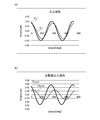
- FIG. 12 is a diagram for explaining a phase difference between signal waveforms.
- 12 (a) shows a relationship between the second audio signal v L waveform first audio signal v R and the left microphone 16b to the right microphone 16a is generated is produced.
- the relationship between the first positive phase signal V R + and the second positive phase signal V L + obtained by amplifying the first audio signal v R and the second audio signal v L to the same magnification is shown. Yes.
- the sound source is arranged on the right side when viewed from the housing 20 of the robot 10, and the phase of the first positive phase signal V R + slightly advances from the second positive phase signal V L +. Also, the amplitude of the first positive phase signal V R + is higher.
- FIG. 12B shows the relationship between the waveforms of the output signal V rOUT of the first adder 86a and the output signal V lOUT of the second adder 86b. Compared with the phase difference of the input waveform shown in FIG. 12A, it can be seen that the phase difference of the output waveform of the adder shown in FIG. 12B is widened (amplified).
- FIG. 13 is a diagram for explaining the principle of amplifying the phase difference of the input signal waveform.
- FIG. 13A shows the first positive phase signal V R + and the first negative phase signal V R ⁇ , the second positive phase signal V L + and the second negative phase signal V L ⁇ in a two-dimensional coordinate system. is doing.
- the phase difference between the first positive phase signal V R + and the second positive phase signal V L + is ⁇ .
- FIG. 13 (b) shows the output signal V ROUT of the first adder 86a and the output signal V LOUT of the second adder 86b.
- the phase difference between V rOUT and V 1OUT is ⁇ ′, which is larger than the phase difference ⁇ shown in FIG.
- the phase difference amplifying device 82a amplifies the phase difference between the two input audio signals.
- the phase difference of the input signal is about 5 to 20 degrees, and the phase difference amplifying device 82a can increase the amplification factor in this range, so that the phase difference of the output signal can be determined by the user. It is widened to the extent that you can hear the direction.
- the output signals V ROUT and V LOUT from the phase difference amplifying device 82a are each audio-encoded and transmitted from the transmission unit 90 to the HMD 100 as audio data for the right ear and audio data for the left ear.
- the right ear sound data is output as sound from the right ear earphone 104
- the left ear sound data is output as sound from the left ear earphone 104.
- User A recognizes the direction of the sound source by listening to the sound with the amplified phase difference from both ears. If the user A feels that a voice has been heard from the right side, the user A turns his face to the right side. At this time, since the housing 20 of the robot 10 faces the right side in conjunction with the movement of the face of the user A (see FIG. 2), the camera 14 of the robot 10 captures the environment on the right side and captures the captured image data in real time. Send to HMD100. As a result, the user A can speak while looking at the face of the person who speaks, and can realize an unprecedented excellent user interface.
- the values of ⁇ and ⁇ are preferably set appropriately by experiment.
- the right microphone 16 a and the left microphone 16 b are provided at positions where the side surface of the housing 20 is recessed and at the back side when viewed from the front. Since the sound wave transmission structure in the microphone 16 depends on the shape of the side surface of the housing, the ratio of ⁇ and ⁇ is preferably determined optimally through experiments.
- the microphone 16 is disposed inside the rear plate 17 in the lateral direction.
- the rear plate 17 has a function of making the frequency characteristics of the sound wave from the front and the sound wave from the rear different from each other and reducing the high frequency component from the rear.
- the rear plate 17 has a function like a human auricle with respect to the microphone 16, and a sound wave from the rear wraps around the rear plate 17 and reaches the microphone 16.
- the rear plate 17 may be formed to be further expanded in the vertical direction and the horizontal direction. By forming a sound wave shield such as the rear plate 17 behind the microphone 16, the user A can also recognize the position of the sound source in the front-rear direction.
- the user A can freely communicate with the people around the robot 10 in real time using the robot 10 which is his or her own character.
- the technique which further raises the usability of the information processing system 1 is proposed.
- the robot 10 points around the camera 14 in the line-of-sight direction according to the movement of the user A's head, and images the surroundings. As the user A faces various directions, the camera 14 captures various directions. It is possible to generate a virtual omnidirectional panoramic image by adding a three-dimensional vector representing the line-of-sight direction to this captured image and recording it.
- FIG. 14 shows a modification of the functional block of the robot 10. This functional block is based on the functional block shown in FIG. 10, and shows that the determined visual line direction is supplied from the visual line direction determining unit 66 to the image processing unit 80.
- the transmission unit 90 transmits the image data for both eyes and the sound data for both ears (hereinafter sometimes collectively referred to as “viewing data”) via the network 4 to the user A.
- viewing data the image data for both eyes and the sound data for both ears
- the transmission unit 90 transmits the same viewing data to the processing device 200 via the network 4 via the router 5, and the processing device 200 records the viewing data of the user A.
- the processing device 200 generates the omnidirectional panoramic image in real time based on the image data of the user A while recording the viewing data of the user A, and displays an image corresponding to the viewing direction of the user B different from the user A.
- B has a function provided to the HMD 100a.
- the HMD 100a has the same configuration as the HMD 100 described so far.
- the processing device 200 may be configured by a single server, for example, but may be configured by a server group that provides a cloud service.
- the image processing unit 80 includes vector information indicating the line-of-sight direction supplied from the line-of-sight direction determination unit 66 and the start of shooting for each frame image data.
- Shooting time information indicating the elapsed time from the point is added.
- the vector information indicates the line-of-sight direction of the camera 14 of the robot 10.
- the shooting time information only needs to express the time from the shooting start point, and may be a frame number indicating the order of shooting, for example.
- the user B wears the HMD 100a and provides the HMD 100a with image data and audio data generated based on the viewing data of the user A supplied from the robot 10.
- the processing device 200 may simply stream the received viewing data to the HMD 100a of the user B as it is.
- An image based on the line-of-sight direction of the user B is reconstructed from the panoramic image formed based on the image data, and can be provided to the user B's HMD 100a.
- the audio data is streamed to user B's HMD 100a.
- FIG. 15 shows functional blocks of the processing apparatus 200.
- the processing device 200 includes a reception unit 202, a sensor information acquisition unit 204, a motion detection unit 206, a line-of-sight direction determination unit 208, an image determination unit 210, an audio determination unit 212, a viewing data provision unit 214, a transmission unit 216, and a recording unit 218.
- the recording unit 218 includes an image recording unit 220 and an audio recording unit 222.
- the receiving unit 202 receives the viewing data transmitted from the robot 10
- the image recording unit 220 sequentially records the received image data
- the audio recording unit 222 sequentially records the received audio data.
- the image data is added with vector information and shooting time information at the time of shooting for each frame image.
- User B transmits an instruction to reproduce viewing data of the user A to the processing device 200 through the HMD 100a.
- the processing device 200 starts playback processing of viewing data.
- the audio determination unit 212 determines audio data to be provided to the user B, and immediately reads out the audio data recorded in the audio recording unit 222 from the audio recording unit 222 and provides it to the viewing data providing unit 214. That is, the sound determination unit 212 distributes the sound data provided from the robot 10 to the HMD 100a in a streaming manner. Therefore, the user B can hear the same sound as the sound that the user A is listening from the earphone 104 of the HMD 100a.
- the reception unit 202 receives sensor information transmitted from the HMD 100a worn by the user B, and the sensor information acquisition unit 204 acquires the received sensor information.
- This sensor information is posture information obtained by the posture sensor 124 detecting the posture of the HMD 100a.
- the motion detection unit 206 detects the posture of the HMD 100a mounted on the user B's head.
- the line-of-sight direction determination unit 208 determines the line-of-sight direction of the virtual camera in the omnidirectional panoramic image according to the attitude of the HMD 100 a detected by the motion detection unit 206.
- the image determination unit 210 determines image data to be provided to the user B, and uses the plurality of image data recorded in the image recording unit 220 to synthesize an image photographed by the virtual camera toward the determined line-of-sight direction. To generate image data.
- the viewing data providing unit 214 provides viewing data, which is a combination of the image data determined by the image determining unit 210 and the sound data determined by the sound determining unit 212, to the HMD 100a of the user B from the transmitting unit 216.
- each element described as a functional block for performing various processes can be configured by a circuit block, a memory, and other LSIs in terms of hardware, and loaded in the memory in terms of software. Realized by programs. Therefore, it is understood by those skilled in the art that these functional blocks can be realized in various forms by hardware only, software only, or a combination thereof, and is not limited to any one.
- the processing device 200 generates a panoramic image in all directions. Therefore, when the user B turns his / her neck left or right and rotates the horizontal line of sight to the left or right, the panorama image in the left or right direction is displayed on the display panel 102 of the HMD 100a, and the user B By tilting up or down and tilting the line of sight in the vertical direction, a panoramic image in the upward or downward direction is displayed on the display panel 102 of the HMD 100a.
- FIG. 16 is a diagram for explaining an omnidirectional panoramic image generated by the processing device 200.
- a virtual environment in which a visible image is changed is realized by the user B being positioned at the center of the sphere and changing the direction of the line of sight.
- the image determining unit 210 stitches the image data recorded in the image recording unit 220 to generate an omnidirectional panoramic image.
- the robot 10 does not zoom the camera 14 and acquires image data at a constant magnification. Therefore, the image determination unit 210 forms an omnidirectional panoramic image by pasting the image data onto the inner peripheral surface of the omnidirectional sphere based on the vector information added to the image data. It should be noted that a portion where a plurality of image data overlap is overwritten with the latest image data, so that an omnidirectional panoramic image close to a real-time situation can be constructed.
- the actual image generation processing of the image determination unit 210 does not always reconstruct the omnidirectional panoramic image in order to reduce the processing load, but the frame image 7 taken from the center point 9 where the user B is located. Is a process of dynamically generating.
- the image determination unit 210 preferably sets the shooting range (view angle) of the virtual camera 8 so as to correspond to the actual shooting range (view angle) of the camera 14 of the robot 10.
- the image determination unit 210 performs the image stitching process using the vector information set as the metadata in the image data, and generates the frame image 7 in the shooting range determined from the line-of-sight direction of the user B.
- the motion detection unit 206 detects the rotation angle and inclination of the head of the user B (actually, the HMD 100a) by performing the head tracking process of the user B.
- the rotation angle of the HMD 100a is a rotation angle with respect to the reference direction of the horizontal plane, and the reference direction may be set as a direction facing when the power of the HMD 100a is turned on, for example.
- the inclination of the HMD 100a is an inclination angle with respect to the horizontal plane.
- a known technique may be used as the head tracking process, and the motion detection unit 206 detects the rotation angle and inclination of the HMD 100a from the sensor information detected by the attitude sensor of the HMD 100a.
- the line-of-sight direction determination unit 208 determines the posture of the virtual camera 8 in the virtual sphere according to the detected rotation angle and inclination of the HMD 100a.
- the virtual camera 8 is arranged so as to photograph the inner peripheral surface of the virtual sphere from the center point 9 of the virtual sphere, and the line-of-sight direction determination unit 208 changes the direction of the optical axis of the virtual camera 8 to the camera 14 of the robot 10. It may be determined so as to coincide with the optical axis direction.
- the line-of-sight direction determination unit 66 determines the line-of-sight direction of the HMD 100 of the user A as a three-dimensional coordinate vector (x, y, z)
- the line-of-sight direction of the camera 14 of the robot 10 is the same (x, y, It was explained that z) may be determined.
- the line-of-sight direction determination unit 208 determines the line-of-sight direction of the HMD 100a of the user B as a vector (x, y, z) of three-dimensional coordinates
- the line-of-sight direction of the virtual camera 8 is the same (x, y, z) may be determined.
- the gaze direction determination unit 208 When the gaze direction determining unit 66 determines the gaze direction of the camera 14 by correcting the gaze direction of the HMD 100 with a predetermined conversion formula, the gaze direction determination unit 208 also corrects the gaze direction of the HMD 100a with the same conversion formula. Then, the line-of-sight direction of the virtual camera 8 may be obtained. In this way, by handling each three-dimensional coordinate system, the user B can see the same image as the user A at the timing when the line-of-sight direction of the user A matches the line-of-sight direction of the user B. .
- the image determination unit 210 When the image determination unit 210 generates the frame image 7 of the virtual camera 8, the image determination unit 210 performs optical distortion correction for the optical lens and supplies image data to the viewing data providing unit 214.
- one virtual camera 8 In FIG. 16, one virtual camera 8 is shown. Actually, however, two virtual cameras 8 for the left eye and the right eye are arranged, and each image data is provided for the left eye provided from the robot 10. It is generated based on the image data and the right-eye image data.
- FIG. 17 is a diagram for explaining the captured image data recorded in the image recording unit 220.
- a plurality of image data for one eye is shown, and image data in a state in which an appropriate affine transformation is applied to the user B's line-of-sight direction is arranged on a two-dimensional plane. Note that the line-of-sight direction of the user B will be described later.
- the image determination unit 210 has a function of generating overlapping panoramic images by connecting overlapping portions of the captured images.
- a technique for joining photographed images for example, a known technique may be used as described in Japanese Patent No. 5865388 by the same applicant.
- a method for selecting which captured image data to use from among a plurality of captured image data recorded in the image recording unit 220 will be described.
- FIG. 17 shows five image data I1 to I5.
- (X, y, z) included in each image data represents the viewing direction (vector information) of the camera 14 at the time of photographing, and “t” represents photographing time information.
- the image data I1 has vector information (x1, y1, z1) and shooting time information t1 as additional information.
- the image data I2 has vector information (x2, y2, z2) and shooting time information t2 as additional information
- the image data I3 has vector information (x3, y3, z3) and shooting time information t3 as additional information.
- the image data I4 includes vector information (x4, y4, z4) and shooting time information t4 as additional information
- the image data I5 includes vector information (x5, y5, z5) and shooting time information t5. It has as additional information.
- the shooting time information t1 to t5 which is additional information, represents an elapsed time from the shooting start point (time 0) and has a relationship of t1 ⁇ t2 ⁇ t3 ⁇ t4 ⁇ t5. Accordingly, among the image data I1 to I5, the image data I1 is photographed first, and the image data I5 is photographed last.
- the image determination unit 210 selects image data for generating a composite image based on the shooting time information and the visual line direction of the virtual camera 8 determined by the visual line direction determination unit 208.
- the image determination unit 210 captures a shooting range (virtual camera) cut from the panoramic image from the gaze direction of the virtual camera 8 determined by the gaze direction determination unit 208, that is, the direction in which the user B wearing the HMD 100a faces. 8) and image data including an image included in the shooting range is extracted based on vector information added to the image data.
- a shooting range virtual camera
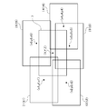
- FIG. 18 is a diagram illustrating a relationship between the frame image 7 to be generated by the image determination unit 210 and the image data.
- each image data I1 to I5 is mapped on a two-dimensional plane orthogonal to the viewing direction (X, Y, Z) of the virtual camera 8 based on each vector information.
- the positions of the data I1 to I5 are defined by four vertex coordinates on the two-dimensional plane.
- the image determination unit 210 determines the position (shooting range) of the field angle of the virtual camera 8 in the panoramic image based on the line-of-sight direction (X, Y, Z) of the virtual camera 8, and is a two-dimensional plane orthogonal to the line-of-sight direction.
- the four vertex coordinates of the frame image 7 are determined.
- the image determination unit 210 extracts image data included in the frame image 7 from the image data recorded in the image recording unit 220. As illustrated, the image data I1 to I5 include images included in the frame image 7, and thus are extracted as image data included in the shooting range of the virtual camera 8.
- the image determination unit 210 generates a composite image by preferentially using image data having late shooting time information for a region where a plurality of image data overlap.
- the frame image 7 is combined with the frame image 7 so that the image data is written in order from the image data with the earliest shooting time, that is, in order from the image data I1.
- the image determination unit 210 generates a composite image using image data having shooting time information closer to the current time for overlapping regions of a plurality of image data. For example, in the image included in the shooting range, when there is an overlapping portion between the image data I4 and the image data I5, the image data I5 having a later shooting time is embedded in the overlapping portion. As a result, a composite image can be generated using image data close to the current time, and a composite image close to the current time can be provided to the user B.
- image data may be insufficient and it may be difficult to generate the frame image 7.
- the number of image data is small in the first place, so that the image determination unit 210 may not be able to generate the frame image 7 according to the user B's line-of-sight direction.
- the vector information of the image data recorded in the image recording unit 220 is all the same.
- the image determination unit 210 generates image data in which a message indicating that an image in the line-of-sight direction of the user B cannot be generated is superimposed on the received image data of the user A, and the viewing data providing unit 214 sends the image data to the HMD 100a. May be provided.
- the image determination unit 210 does not generate a synthesized image and provides viewing data for the image data viewed by the user A together with the above message It may be supplied to the unit 214.
- the image determination unit 210 synthesizes the frame image 7 from a plurality of image data, the generated frame image 7 becomes a patch image and the visibility may be deteriorated. Therefore, for example, when an image of a predetermined ratio (for example, 50%) within the shooting range cannot be formed from one image data, as described above, the image determination unit 210 cannot generate an image in the line-of-sight direction of the user B.
- the image data may be generated by superimposing the above message on the image data of the user A.
- the image determination unit 210 generates a composite image by using image data having late shooting time information preferentially.
- a frame can be generated by using image data having earlier shooting time information.
- image data having earlier shooting time information may be used.
- the image determination unit 210 may perform image extraction processing so that image data older than a predetermined time is not included in the composite image.
- the processing device 200 records the viewing data for the secondary use, not for the purpose of real-time reproduction of the viewing data of the user A.
- the image processing unit 80 adds shooting time information and vector information to each of the frame image data, and the audio processing unit 82 adds the recording start point to the audio data. Recording time information indicating the elapsed time from is added. Note that since shooting (recording) by the camera 14 and recording by the microphone 16 are started at the same timing, the shooting start point and the recording start point indicate the same timing.
- the shooting time information and the recording time information may be time information generated by a clock generation unit in the robot 10. Any format may be used for adding the additional information to the image data and the audio data as long as the processing device 200 can refer to the viewing data for reproduction.
- another user B wears the HMD 100 a and the viewing data of the user A recorded in the processing device 200 is stored.
- generated image data and audio data are provided to the HMD 100a.
- the processing device 200 constructs an omnidirectional panoramic image based on the viewing data of the user A, and regenerates an image based on the viewing direction of the user B from the omnidirectional panoramic image. It is configured so that it can be provided to the HMD 100a of the user B. In this usage environment, the robot 10 is not used.
- the image recording unit 220 records the image data transmitted from the robot 10, and the audio recording unit 222 records the audio data transmitted from the robot 10.
- the image recording unit 220 and the audio recording unit 222 are in a state where all the viewing data transmitted from the robot 10 to the user A has been recorded.
- the image data is added with shooting time information and vector information at the time of shooting, and the audio data is added with recording time information.
- User B transmits an instruction to reproduce viewing data of the user A to the processing device 200 through the HMD 100a.
- the processing device 200 starts playback processing of viewing data.
- the recording unit 218 records viewing data for one hour
- the user B may be allowed to start playback from any time within the range of one hour.
- the receiving unit 202 receives time designation from the user B and supplies it to the image determining unit 210 and the sound determining unit 212.
- the audio determination unit 212 reads audio data having recording time information corresponding to the reproduction time information indicating the elapsed time from the reproduction start point from the audio recording unit 222, and provides the audio data to the viewing data providing unit 214.
- the playback start point means a playback start point of viewing data, and therefore indicates the same timing as the shooting start point and the recording start point.
- the audio determination unit 212 reads out audio data whose recording time information matches the reproduction time information from the audio recording unit 222 and provides it to the viewing data providing unit 214.
- the reception unit 202 receives sensor information transmitted from the HMD 100a worn by the user B, and the sensor information acquisition unit 204 acquires the received sensor information.
- This sensor information is posture information obtained by the posture sensor 124 detecting the posture of the HMD 100a.
- the motion detection unit 206 detects the posture of the HMD 100a mounted on the user B's head.
- the line-of-sight direction determination unit 208 determines the line-of-sight direction of the virtual camera according to the posture of the HMD 100a detected by the motion detection unit 206.
- the image determination unit 210 uses the plurality of image data recorded in the image recording unit 220 to synthesize an image photographed by the virtual camera oriented in the determined line-of-sight direction.
- the viewing data providing unit 214 provides viewing data, which is a combination of the image data combined by the image determining unit 210 and the audio data read by the audio determining unit 212, from the transmitting unit 216 to the HMD 100a.
- the image determination unit 210 stitches the images viewed by the user A before the reproduction time of the viewing data by the user B, and dynamically generates a frame image 7 photographed from the center point 9 where the user B is located. To do.
- the playback time from the playback start point by the user B is specified at some timing within one hour. For example, if the playback time is 15 minutes from the start of playback, an image to which shooting time information within 15 minutes has been added, that is, an image shot until 15 minutes have passed since the start of shooting is displayed before the playback time. The image viewed by the user A is displayed.
- the image determination unit 210 determines the frame image 7 using the image data to which shooting time information within 15 minutes from the start of shooting is added, and plays back. If the time point of 45 minutes from the start is being played back, the image determination unit 210 generates the frame image 7 using image data to which shooting time information within 45 minutes from the start of shooting is added.
- the image determination unit 210 extracts image data to which shooting time information before the playback time information is added, and extracts image data to which shooting time information after the playback time information is added. Do not extract. For example, if the time information for reproducing the frame image 7 is after the time t3 and before the time t4, the image determination unit 210 extracts the image data I1 to I3 and does not extract the image data I4 and I5. . As described above, by generating a composite image using image data to which shooting time information before playback time information is added, the image determination unit 210 does not show the user B an image shot after the playback time. Like that.
- the viewing data providing unit 214 transmits audio data having recording time information corresponding to the reproduction time to the HMD 100a, the user B is listening to the audio synchronized with the reproduction time. Therefore, the situation before the reproduction time is generally known, and if the provided image data is synthesized from the image data before the reproduction time, it is possible to grasp what kind of situation is displayed. However, if the provided image data is synthesized from image data after the reproduction time, the user B will be shown an image that he / she does not know, and it is expected that the user B will be confused. Therefore, the image determination unit 210 prevents the user B from seeing an image taken after the reproduction time.
- the image determination unit 210 generates a composite image using image data having shooting time information close to reproduction time information for overlapping portions of the plurality of image data. For example, in the case where an image included in the imaging range includes an overlapping portion between the image data I1 and the image data I2, the image data I2 captured later is embedded in the overlapping portion. As a result, a composite image can be generated using image data close to the reproduction time information, and an image synthesized from image data with the latest reproduction time can be provided to the user B.
- the image determination unit 210 performs the image stitching process and generates the frame image 7 in the shooting range determined from the user B's line-of-sight direction.
- the image determination unit 210 performs the user based on the line-of-sight direction of the virtual camera 8 and the vector information added to the image data recorded in the image recording unit 220 without performing the image stitching process.
- the image data to be provided to B is determined.
- the image determination unit 210 determines the image data to which the vector information corresponding to the viewing direction of the virtual camera 8 is added as the image data to be provided to the user B.
- the vector information corresponding to the line-of-sight direction of the virtual camera 8 includes vector information that matches the line-of-sight direction of the virtual camera 8 and vector information that can be considered to substantially match the line-of-sight direction of the virtual camera 8.
- the image determination unit 210 substantially determines that the visual line direction of the virtual camera 8 and the vector information are substantially the same. It may be determined that they match.
- the image determination unit 210 converts the image data having the latest shooting time information from among the image data to which the vector information corresponding to the line-of-sight direction of the virtual camera 8 is added. Determined as image data to be provided. As a result, an image close to the current time can be provided to the user B.
- the image determination unit 210 removes the component in the height direction (z-axis direction) (x , Y) Image data to which vector information that can be regarded as substantially matching components may be determined as image data to be provided to the user B.
- the vector information that can be regarded as matching is vector information in which the (x, y) component is within a predetermined angle (for example, 7 degrees).
- the image determination unit 210 determines image data to be provided to the user B from images viewed by the user A before the playback time of the viewing data by the user B. That is, the image determination unit 210 determines image data to which vector information corresponding to the line-of-sight direction of the virtual camera 8 is added from among image data to which shooting time information before reproduction time information is added. At this time, when there are a plurality of corresponding image data, the image determination unit 210 preferably selects image data having shooting time information close to reproduction time information.
- the robot 10 may further include an input sensor that accepts an external input, such as a tactile sensor or a vibration sensor.
- an external input such as a tactile sensor or a vibration sensor.
- the input sensor is provided in the output system 24, and sensor information of the input sensor is transmitted from the transmission unit 90 to the HMD 100.
- the HMD 100 may include an output unit that outputs sensor information, and may convert the sensor information into vibration or the like and transmit it to the user A.
- the robot 10 interlocks the housing 20 with the movement of the neck of the user A.
- the information processing system 1 may further include means for transmitting a state such as the facial expression of the user A.
- the HMD 100 includes a sensor that detects the movement of the user A's eyes and eyebrows, a means for analyzing the tone of voice, and the like. The movements of the eyes and eyebrows express the user's facial expressions and emotions, and the tone of the voice expresses the user's psychological state and emotions.
- the state information regarding the movement of the eyes and eyebrows and / or the tone of the voice is transmitted from the HMD 100 to the robot 10, and the robot 10 drives the facial expression unit provided in the housing 20 to reproduce the facial expression and emotion of the user A.
- the facial expression unit may be a movable member (for example, imitating the shape of an eyebrow) formed on the upper surface of the camera 14 on the front surface of the housing 20, and the movable member is driven based on information transmitted from the HMD 100.
- the protective cover 19 that is rotatably attached to the upper part of the camera 14 may be used as an expression unit imitating a human eyebrow.
- a motor that moves the protective cover 19 is provided in the housing 20, and the protective cover 19 is provided. You may move.
- the facial expression unit may be a display that expresses the facial expression and psychological state of the user A with colors, and may express the facial expression and emotion of the user A by changing the display color.
- the movable member provided in the robot 10 will be described.
- the movable member is provided to create the facial expression of the robot 10.
- the movement of the movable member may be controlled so as to express the facial expression and emotion of the user A wearing the HMD 100, but may be controlled based on the attitude of the housing 20.
- the robot 10 not only moves the housing 20 but also moves the movable member attached to the housing 20 to provide a person around the robot 10 as if the robot 10 is the user A. .
- the posture of the housing 20 can be changed by the actuator device 12, and the actuator device 12 links the posture of the housing 20 with the movement of the HMD 100 worn by the user A.
- the housing 20 and the actuator device 12 constitute the robot 10, and the housing 20 constitutes the face of the robot 10.
- “to configure the face of the robot” is to form the casing 20 so that when a person around the robot 10 looks at the robot 10, the casing 20 can be recognized as a face.
- the point to be recognized as a face is that the housing 20 is located at the top of the robot 10 and includes the camera 14 corresponding to the human eye, and the posture of the housing 20 is linked to the movement of the user's neck. By holding these points, the housing 20 is recognized as the face of the robot 10.
- FIG. 19A shows a schematic structure of the front surface of the housing 20, and FIG. 19B shows a schematic structure of the top surface of the housing 20.
- the housing 20 includes a front plate that exposes the lens of the camera 14, a bottom plate that is connected to the front plate and to which the insertion member 42 is attached, a rear plate 17 that is connected to the bottom plate and faces the front plate, and the rear plate 17 and the front plate. And an upper plate that is connected to face the bottom plate, and further includes a front plate, a bottom plate, a rear plate 17 and a pair of side plates that close both ends of the upper plate. 9 and the like show a state in which the rear plate 17 protrudes rearward.
- FIGS. 19 (a) and 19 (b) the housing 20 is shown in FIGS. 19 (a) and 19 (b). Is shown as having a rectangular parallelepiped that is long in the lateral direction. 19A shows a state in which the front plate is removed, and a schematic top view in FIG. 19B shows a state in which the upper plate has been removed. 14, the wiring including the microphone 16 and the power line and the control signal line of the drive motor 142 are not shown.
- a structure for fixing various components is provided in the housing 20.
- the microphone storage portions 11a and 11b are provided on the inner walls of the side plates and form spaces for storing the right microphone 16a and the left microphone 16b, respectively.
- the right microphone 16a and the left microphone 16b are inserted and fixed to the microphone storage portions 11a and 11b from the front.
- the right camera 14a and the left camera 14b are fixed with screws 15 to a camera support portion 13 that protrudes forward from the inner wall of the rear plate 17.
- a motor fixing unit 140 is formed between the right camera 14 a and the left camera 14 b, and the drive motor 142 is fixed to the motor fixing unit 140.
- the protective cover 19 which is a movable member is a rectangular plate member, and is operably supported by the housing 20.
- the protective cover 19 has rotating shafts 19a and 19b projecting inward at both ends in the longitudinal direction. Shaft holes are formed in the vicinity of the front edges of the upper portions of the pair of side plates of the housing 20, the rotation shaft 19a is inserted into the shaft hole of the right side plate, and the rotation shaft 19b is inserted into the shaft hole of the left side plate.
- the protective cover 19 is rotatably supported by the housing 20.
- At least one of the rotating shaft 19a and the rotating shaft 19b is inserted into the housing beyond the inner wall of the side plate, and is connected to the motor shaft 142a of the drive motor 142 inside the housing.
- both of the rotation shafts 19a and 19b have entered the inner side of the inner wall of the housing side plate, and the rotation shaft 19b is fixed to one end of the transmission member 144.
- the transmission member 144 is a member that transmits the rotation of the drive motor 142 to the protective cover 19 that is a movable member.
- One end of the transmission member 144 is fixed to the rotary shaft 19 b, and the other end is fixed to the motor shaft 142 a of the drive motor 142.
- the other end of the transmission member 144 may be directly connected to the motor shaft 142a, but may be fixed to an output shaft of a speed reduction mechanism that decelerates motor rotation.
- the protective cover 19 is connected to the drive motor 142 by the transmission member 144 and is moved between a closed position for protecting the camera 14 and other positions.
- the protective cover 19 protects the camera 14 while the power of the robot 10 is turned off.
- the protective cover 19 operates as an expression unit while the power is turned on, so that the protective cover 19 is effectively used.
- the transmission member 144 is formed as a member that undergoes torsional elastic deformation.
- the transmission member 144 is a coil spring, and the rotation input of the motor shaft 142a is delayed in time by the coil spring being twisted and rotated and output to the rotation shaft 19b.
- the torsion generated in the coil spring becomes a restoring force, and is delayed from the rotation input of the motor shaft 142a to rotate the coil spring in a direction to cancel the torsion.
- the transmission member 144 has bending elasticity with respect to the axial direction. As shown in the drawing, since various components are accommodated in the housing 20, the space for arranging the drive motor 142 is limited. Since the transmission member 144 has bending elasticity with respect to the axial direction, even if the motor shaft 142a and the rotation shaft 19b are not on the same axis, the transmission member 144 can be coupled in a state where the transmission member 144 is bent in the axial direction.
- FIGS. 19A and 19B show a state in which the transmission member 144 connects the motor shaft 142a and the rotating shaft 19b in a bent state so as to absorb the misalignment between the motor shaft 142a and the rotating shaft 19b.
- the transmission member 144 having torsional elasticity is employed is to delay the rotation of the rotating shaft 19b with respect to the rotation of the motor shaft 142a.
- the drive motor 142 drives the protective cover 19 according to the posture of the housing 20 and the emotion information of the user, etc., but the protective cover 19 is on the eyes of the robot (camera 14). It becomes like an eyebrow.
- the protective cover 19 reciprocates at high speed, the movement of the facial expression unit is not ideal because it feels unsatisfactory as seen by the surrounding people and is different from the movement of the human eyebrows.
- the torsional rigidity of the transmission member 144 is high, it is difficult to cause a delay in transmission response to the rotating shaft 19b. Therefore, it is preferable to set the torsional rigidity low. Also depends on weight. Therefore, in order to increase the response delay, the weight of the protective cover 19 may be increased.
- coil springs having various characteristics are on the market, and it is advantageous from the viewpoint of cost to use the transmission member 144 as a coil spring.
- the transmission member 144 is a solid rod-shaped member made of a rubber material. It is good also as a member. By forming the transmission member 144 from a rubber material, it is possible to provide torsional elasticity and bending elasticity.
- FIG. 20 shows functional blocks of the input system 22 in the robot 10.
- the functional blocks shown in FIG. 20 are added to the input system 22 shown in FIG. 10, and FIG. 20 shows only the configuration for driving and controlling the protective cover 19.
- the input system 22 includes a receiving unit 60, an actuator control unit 68, a state information acquisition unit 74, a drive control unit 76, and an operation table 78.
- each element described as a functional block for performing various processes can be configured by a circuit block, a memory, and other LSIs in terms of hardware, and loaded into the memory in terms of software. Realized by programs. Therefore, it is understood by those skilled in the art that these functional blocks can be realized in various forms by hardware only, software only, or a combination thereof, and is not limited to any one.
- the actuator control unit 68 stands up 90 degrees with respect to the base 30 with respect to the first arcuate arm 32 and the second arcuate arm 34.
- the first motor 52 and the second motor 54 are driven.
- the rotation angle ⁇ x of the first motor 52, the rotation angle ⁇ y of the second motor 54, and the rotation angle ⁇ z of the third motor 56 are set to reference values (for example, 0), with the posture of the housing 20 at this time as a reference posture. That is, ( ⁇ x, ⁇ y, ⁇ z) is set to (0, 0, 0) in the reference posture.
- FIGS. 21A to 21C show the positional relationship between the casing side plate and the protective cover 19. While the power of the robot 10 is off, the protective cover 19 is disposed at a closed position that protects the camera 14.
- FIG. 21A shows a state in which the protective cover 19 covers the front surface of the housing 20 and protects the camera 14.
- the drive control unit 76 controls the rotation of the drive motor 142 to move the protective cover 19 to the initial operation position.
- the initial operation position is a position where the protective cover 19 is rotated 90 degrees upward from the closed position.
- FIG. 21B shows a state where the protective cover 19 has been moved to the initial operation position.
- the camera 14 can capture the front direction. Note that the initial operation position may be set to a position that does not fall within the viewing angle of the camera 14.
- FIG. 21C shows a state where the protective cover 19 has been moved to the maximum operating position.
- the maximum operation position may be set at a rotation limit position of the protective cover 19 where the protective cover 19 and the upper plate of the casing come into contact, or may be set before that.
- the actuator control unit 68 controls the rotation angles of the first motor 52, the second motor 54, and the third motor 56 according to the sensor information from the HMD 100.
- the actuator control unit 68 provides rotation angle information ( ⁇ x, ⁇ y, ⁇ z) indicating the attitude of the housing 20 to the drive control unit 76, and the drive control unit 76 uses the rotation angle information ( ⁇ x, ⁇ y, ⁇ z).
- the rotation of the drive motor 142 is controlled.
- the drive control unit 76 obtains the rotation angle ⁇ of the drive motor 142 according to the following calculation formula.
- the rotation angle ⁇ at the initial operation position is set to zero.
- ⁇ a ⁇
- express the absolute value of the rotation angle.
- “a”, “b”, and “c” are weighting coefficients for the respective rotation angles, and the operating characteristics of the protective cover 19 are determined according to preference by appropriately setting the weighting coefficients.
- the drive control unit 76 calculates the rotation angle ⁇ based on the rotation angle information ( ⁇ x, ⁇ y, ⁇ z), and supplies power to the drive motor 142 so that the rotation angle of the drive motor 142 becomes ⁇ .
- the behavior of the protective cover 19 linked to the posture of the body 20 can be realized.
- the behavior of the protective cover 19 is linked to the posture of the housing 20.
- control may be performed to raise the protective cover 19.
- the posture of the housing 20 does not change, it is assumed that the user A is concentrating on some object and staring.
- the drive control unit 76 controls the drive motor 142 so that the protective cover 19 is raised.
- the person around the robot 10 knows in advance that the standing of the protective cover 19 expresses that the user A is concentrated.
- the situation of the user A can be expressed by the operation of the protective cover 19.
- the HMD 100 includes a sensor that detects the movement of a specific part of the face of the user A.
- the HMD 100 includes a camera inside and outside the housing 114, and includes a facial expression monitoring unit that monitors facial expressions of the user, specifically, movements of eyes, eyebrows, nose, lips, and the like.
- Various studies have been conducted on the relationship between emotions and facial expressions. The following (1) to (5) are the relationships between emotions and facial expressions that have been published in previous studies. (1) Happiness: The upper end of the lips is raised and pulled back. (2) Surprise: Eyebrows go up and eyes wide open. (3) Disgust: Raises upper lip and wrinkles nose. (4) Anger: Vertical lines are formed between the eyebrows, and the mouth is strongly closed. (5) Sadness: Both ends of the lips are lowered and the line of sight is lowered.
- the relationship between emotions and facial expressions is stored in a database, and the facial expression monitoring unit is configured to read emotion information corresponding to facial expressions by referring to the database when the facial expression of the user A is identified from the camera image. Yes. Since the emotion of a person changes every moment, the facial expression monitoring unit sends the emotion information extracted from the database to the robot 10 every time it determines that a change in emotion has occurred from a change in a specific part included in the camera image. Send.
- the facial expression monitoring unit determines from the camera image that “the upper end of the lips is raised and pulled backward”, the emotion information (“happiness”) associated with the facial expression information is read and transmitted to the robot 10. To do. Thereafter, when the facial expression monitoring unit determines from the camera image that “the eyebrows are raised and the eyes are wide open”, the emotion information (“surprise”) associated with the facial expression information is read and transmitted to the robot 10. To do. If facial expression information detected by the facial expression monitoring unit is not registered in the database, the facial expression monitoring unit transmits emotion information indicating that there is no user emotion to the robot 10. The sent emotion information only needs to be able to identify an emotion, and may be an information ID of emotion information such as No. (1) or No. (2), for example.
- the facial expression monitoring section itself displays facial expression information, for example, facial expression information indicating that the upper end of the lips is raised and pulled backward, or that the eyebrows are raised and the eyes are wide open.
- the facial expression information shown may be transmitted to the robot 10.
- the facial expression monitoring unit may transmit both emotion information and facial expression information to the robot 10.
- state information such facial expression information and / or emotion information is collectively referred to as state information.
- the receiving unit 60 receives the state information, and the state information acquiring unit 74 acquires the state information.
- the drive control unit 76 controls the rotation of the drive motor 142 based on the state information. At this time, the drive control unit 76 refers to the operation table 78.
- the operation table 78 holds facial expression information and / or emotion information in association with the operation mode of the protective cover 19.
- FIG. 22 shows an example of the contents held in the operation table.
- emotion information and the operation mode of the protective cover 19 are recorded in association with each other.
- the drive control unit 76 drives the drive motor 142 so that the protective cover 19 operates in a corresponding operation mode based on the emotion information acquired from the HMD 100. For example, when the emotion information is “happiness”, the drive control unit 76 reciprocates 30 degrees back and forth (with an amplitude of 60 degrees) from the state where the protective cover 19 is raised 90 degrees from the initial operation position. The rotation of the drive motor 142 is controlled.
- the drive control unit 76 may set the reciprocating speed according to the degree.
- the operation table 78 holds emotion information and the operation mode of the protective cover 19 in association with each other, but expression information and operation mode of the protection cover 19 may be stored in association with each other.
- the state information acquisition unit 74 acquires the facial expression information and / or emotion information of the user detected by the HMD 100 worn by the user.
- facial expression information and / or emotion information of the user wearing the HMD 100 may be detected by the HMD 100, but may be detected by an information processing apparatus provided outside the HMD 100. That is, the facial expression monitoring unit may be provided in the HMD 100, but may be provided in an information processing apparatus different from the HMD 100.
- the information processing apparatus specifies the facial expression or emotion of the user based on the camera image captured by the camera that captures the user, and transmits it to the robot 10.
- the state information acquisition unit 74 acquires facial expression information and / or emotion information of the user wearing the HMD 100, and the drive control unit 76 uses the facial expression information and / or emotion information of the user.
- the rotation of the drive motor 142 is controlled.
- SYMBOLS 1 Information processing system, 10 ... Robot, 12 ... Actuator apparatus, 14a ... Right camera, 14b ... Left camera, 16a ... Right microphone, 16b ... Left microphone, 20 ... Case, 22 ... Input system, 24 ... Output system, 30 ... Pedestal, 32 ... First arc arm, 32a ... First through slot, 34 ... Second arcuate arm, 34a, second through hole, 36, housing, 38, cover, 40, leg, 42, insertion member, 42a, first regulating portion , 42b... Second restricting portion, 42c... Shaft portion, 50... Driving mechanism, 52... First motor, 54. ..Reception unit, 62... Sensor information acquisition unit, 64...
- Motion detection unit, 66. 8 ... Actuator control unit, 70 ... Audio data acquisition unit, 72 ... Audio processing unit, 74 ... Status information acquisition unit, 76 ... Drive control unit, 78 ... Operation table, 80 ... Image processing unit, 82 ... Audio processing unit, 82a ... Phase difference amplifying device, 84a ... First amplifier, 84b ... Second amplifier, 86a ... First adder, 86b ... Second adder, 88a ... Third amplifier, 88b ... Fourth amplifier, 90 ... Transmitter, 92 ... Image recording device, 100 ... HMD, 102 ... Display Panel, 104 ... Earphone, 106 ... Microphone, 108 ... Mounting band, 110 ...
- Output mechanism 112 ... Mounting mechanism, 114 ... Case, 120 ... Control unit 122, storage unit, 124, posture sensor, 126, communication Control unit, 142... Drive motor, 144... Transmission member, 200... Processing device, 202 .. reception unit, 204... Sensor information acquisition unit, 206. ..Gaze direction determination unit, 210... Image determination unit, 212... Audio determination unit, 214 .. viewing data providing unit, 216... Transmission unit, 218. Image recording unit, 222... Voice recording unit.
- the present invention can be used in the field of outputting sound.
Landscapes
- Physics & Mathematics (AREA)
- Health & Medical Sciences (AREA)
- Otolaryngology (AREA)
- Engineering & Computer Science (AREA)
- Acoustics & Sound (AREA)
- Signal Processing (AREA)
- General Physics & Mathematics (AREA)
- Optics & Photonics (AREA)
- Circuit For Audible Band Transducer (AREA)
Abstract
Un microphone droit 16a génère un premier signal de parole, et un premier amplificateur 84a délivre un premier signal de phase positive obtenu en amplifiant le premier signal de parole, et un premier signal en opposition de phase obtenu en inversant et en amplifiant le premier signal de parole. Un microphone gauche 16b est disposé dans une position différente de celle du microphone droit 16a et génère un deuxième signal de parole, et un deuxième amplificateur 84b délivre un deuxième signal de phase positive obtenu en amplifiant le deuxième signal de parole, et un deuxième signal en opposition de phase obtenu en inversant et en amplifiant le deuxième signal de parole. Un premier additionneur 86a additionne un signal obtenu en multipliant le premier signal de phase positive par un premier coefficient, et un signal obtenu en multipliant le deuxième signal en opposition de phase par un deuxième coefficient. Un deuxième additionneur 86b additionne un signal obtenu en multipliant le deuxième signal de phase positive par le premier coefficient, et un signal obtenu en multipliant le premier signal en opposition de phase par le deuxième coefficient. Un troisième amplificateur 88a multiplie un signal de sortie du premier additionneur 86a par un troisième coefficient et délivre un signal résultant. Un quatrième amplificateur 88b multiplie un signal de sortie du deuxième additionneur 86b par le troisième coefficient et délivre un signal résultant.
Applications Claiming Priority (2)
| Application Number | Priority Date | Filing Date | Title |
|---|---|---|---|
| JP2016084824A JP6518620B2 (ja) | 2016-04-20 | 2016-04-20 | 位相差増幅装置 |
| JP2016-084824 | 2016-04-20 |
Publications (1)
| Publication Number | Publication Date |
|---|---|
| WO2017183293A1 true WO2017183293A1 (fr) | 2017-10-26 |
Family
ID=60115933
Family Applications (1)
| Application Number | Title | Priority Date | Filing Date |
|---|---|---|---|
| PCT/JP2017/006942 Ceased WO2017183293A1 (fr) | 2016-04-20 | 2017-02-23 | Dispositif d'amplification de différence de phase |
Country Status (2)
| Country | Link |
|---|---|
| JP (1) | JP6518620B2 (fr) |
| WO (1) | WO2017183293A1 (fr) |
Families Citing this family (1)
| Publication number | Priority date | Publication date | Assignee | Title |
|---|---|---|---|---|
| JP7800115B2 (ja) * | 2021-12-22 | 2026-01-16 | 株式会社Jvcケンウッド | 画像表示装置及び画像表示方法 |
Citations (3)
| Publication number | Priority date | Publication date | Assignee | Title |
|---|---|---|---|---|
| JPS6010900A (ja) * | 1983-06-29 | 1985-01-21 | Yuniden Kk | 電話機用スピ−カ・フオン構造 |
| JP2005072642A (ja) * | 2003-08-22 | 2005-03-17 | Kenwood Corp | マイクロホン装置および集音方法 |
| JP2017028603A (ja) * | 2015-07-27 | 2017-02-02 | 株式会社オーディオテクニカ | マイクロホン及びマイクロホン装置 |
-
2016
- 2016-04-20 JP JP2016084824A patent/JP6518620B2/ja active Active
-
2017
- 2017-02-23 WO PCT/JP2017/006942 patent/WO2017183293A1/fr not_active Ceased
Patent Citations (3)
| Publication number | Priority date | Publication date | Assignee | Title |
|---|---|---|---|---|
| JPS6010900A (ja) * | 1983-06-29 | 1985-01-21 | Yuniden Kk | 電話機用スピ−カ・フオン構造 |
| JP2005072642A (ja) * | 2003-08-22 | 2005-03-17 | Kenwood Corp | マイクロホン装置および集音方法 |
| JP2017028603A (ja) * | 2015-07-27 | 2017-02-02 | 株式会社オーディオテクニカ | マイクロホン及びマイクロホン装置 |
Also Published As
| Publication number | Publication date |
|---|---|
| JP6518620B2 (ja) | 2019-05-22 |
| JP2017195521A (ja) | 2017-10-26 |
Similar Documents
| Publication | Publication Date | Title |
|---|---|---|
| WO2017183319A1 (fr) | Robot et boîtier | |
| JP6580516B2 (ja) | 処理装置および画像決定方法 | |
| WO2017183294A1 (fr) | Dispositif actionneur | |
| KR102197544B1 (ko) | 공간화 오디오를 가진 혼합 현실 시스템 | |
| EP3785452B1 (fr) | Appareil et procédé de restitution d'un signal audio à un utilisateur pour lecture | |
| US11758347B1 (en) | Dynamic speech directivity reproduction | |
| JP6565903B2 (ja) | 情報再生装置及び情報再生方法 | |
| JP6538003B2 (ja) | アクチュエータ装置 | |
| CN113396337A (zh) | 使用环境数据的音频增强 | |
| JP7802226B2 (ja) | 視聴覚レンダリング装置およびその動作方法 | |
| JP6615716B2 (ja) | ロボットおよび筐体 | |
| WO2017183292A1 (fr) | Dispositif de traitement et procédé de détermination d'image | |
| WO2017183293A1 (fr) | Dispositif d'amplification de différence de phase | |
| WO2018198777A1 (fr) | Dispositif et programme de fourniture d'image de réalité virtuelle |
Legal Events
| Date | Code | Title | Description |
|---|---|---|---|
| NENP | Non-entry into the national phase |
Ref country code: DE |
|
| 121 | Ep: the epo has been informed by wipo that ep was designated in this application |
Ref document number: 17785638 Country of ref document: EP Kind code of ref document: A1 |
|
| 122 | Ep: pct application non-entry in european phase |
Ref document number: 17785638 Country of ref document: EP Kind code of ref document: A1 |