WO2017183304A1 - 静電気分布計測装置 - Google Patents
静電気分布計測装置 Download PDFInfo
- Publication number
- WO2017183304A1 WO2017183304A1 PCT/JP2017/007452 JP2017007452W WO2017183304A1 WO 2017183304 A1 WO2017183304 A1 WO 2017183304A1 JP 2017007452 W JP2017007452 W JP 2017007452W WO 2017183304 A1 WO2017183304 A1 WO 2017183304A1
- Authority
- WO
- WIPO (PCT)
- Prior art keywords
- measurement object
- distance
- unit
- static electricity
- measurement
- Prior art date
- Legal status (The legal status is an assumption and is not a legal conclusion. Google has not performed a legal analysis and makes no representation as to the accuracy of the status listed.)
- Ceased
Links
Images



Classifications
-
- G—PHYSICS
- G01—MEASURING; TESTING
- G01R—MEASURING ELECTRIC VARIABLES; MEASURING MAGNETIC VARIABLES
- G01R29/00—Arrangements for measuring or indicating electric quantities not covered by groups G01R19/00 - G01R27/00
- G01R29/12—Measuring electrostatic fields or voltage-potential
- G01R29/14—Measuring field distribution
-
- G—PHYSICS
- G01—MEASURING; TESTING
- G01R—MEASURING ELECTRIC VARIABLES; MEASURING MAGNETIC VARIABLES
- G01R29/00—Arrangements for measuring or indicating electric quantities not covered by groups G01R19/00 - G01R27/00
- G01R29/12—Measuring electrostatic fields or voltage-potential
-
- G—PHYSICS
- G01—MEASURING; TESTING
- G01R—MEASURING ELECTRIC VARIABLES; MEASURING MAGNETIC VARIABLES
- G01R29/00—Arrangements for measuring or indicating electric quantities not covered by groups G01R19/00 - G01R27/00
- G01R29/24—Arrangements for measuring quantities of charge
-
- G—PHYSICS
- G01—MEASURING; TESTING
- G01B—MEASURING LENGTH, THICKNESS OR SIMILAR LINEAR DIMENSIONS; MEASURING ANGLES; MEASURING AREAS; MEASURING IRREGULARITIES OF SURFACES OR CONTOURS
- G01B21/00—Measuring arrangements or details thereof, where the measuring technique is not covered by the other groups of this subclass, unspecified or not relevant
- G01B21/16—Measuring arrangements or details thereof, where the measuring technique is not covered by the other groups of this subclass, unspecified or not relevant for measuring distance of clearance between spaced objects
-
- G—PHYSICS
- G01—MEASURING; TESTING
- G01B—MEASURING LENGTH, THICKNESS OR SIMILAR LINEAR DIMENSIONS; MEASURING ANGLES; MEASURING AREAS; MEASURING IRREGULARITIES OF SURFACES OR CONTOURS
- G01B7/00—Measuring arrangements characterised by the use of electric or magnetic techniques
- G01B7/28—Measuring arrangements characterised by the use of electric or magnetic techniques for measuring contours or curvatures
- G01B7/287—Measuring arrangements characterised by the use of electric or magnetic techniques for measuring contours or curvatures using a plurality of fixed, simultaneously operating transducers
-
- G—PHYSICS
- G01—MEASURING; TESTING
- G01R—MEASURING ELECTRIC VARIABLES; MEASURING MAGNETIC VARIABLES
- G01R29/00—Arrangements for measuring or indicating electric quantities not covered by groups G01R19/00 - G01R27/00
- G01R29/08—Measuring electromagnetic field characteristics
- G01R29/0807—Measuring electromagnetic field characteristics characterised by the application
- G01R29/0814—Field measurements related to measuring influence on or from apparatus, components or humans, e.g. in ESD, EMI, EMC, EMP testing, measuring radiation leakage; detecting presence of micro- or radiowave emitters; dosimetry; testing shielding; measurements related to lightning
Definitions
- the present invention is a component used in a manufacturing process in various manufacturing sites such as semiconductor manufacturing, electronic / electric equipment manufacturing, precision machine manufacturing, transport machine manufacturing, chemical manufacturing, fiber manufacturing, ceramics manufacturing, chemical manufacturing and food manufacturing.
- the present invention relates to a static electricity distribution measuring device that measures a charge distribution of static electricity in a product including a metal or an insulator.
- the manufactured product becomes a defect or a defective product as a matter of course, and there is a problem that the manufacturing yield decreases.
- the product after manufacture may be defective or defective for various reasons.
- problems related to both the former and the latter there are problems in that, in an automated manufacturing process, if a malfunction occurs in each process, the manufacturing speed (manufacturing efficiency) decreases or the manufacturing yield of the product decreases.
- the device is designed to prevent static electricity from affecting parts, products, and manufacturing processes. Specifically, floors, walls, conveyor lines, etc. are de-charged before starting work, or grounding for static elimination is provided, so that parts and products used in the manufacturing process are not charged with static electricity. Has been made.
- parts used for manufacturing such electronic devices and precision devices There are various types of parts used for manufacturing such electronic devices and precision devices. For example, many parts made of resin or vinyl (connectors, screen covers, housings, etc.) are also used. These parts are of a certain size and can behave unpredictably when charged with static electricity.
- a plurality of parts enter a process of being arranged at a fixed position by flowing through a conveyor line, or enter a process of appearance inspection by image processing.
- a plurality of parts thrown into the conveyor line flow through the conveyor line while keeping a throwing interval.
- the mechanism leading to the actual behavior is hardly elucidated.
- parts may show different behaviors such as approaching or moving away, or may not show any behavior at all. For this reason, it is difficult to elucidate the mechanism leading to the behavior if it is not known how the static electricity charged to the component (considered) is distributed in the component. If it is difficult to elucidate the mechanism, naturally, it is not possible to examine a countermeasure for preventing the above-described behavior.
- a cover formed of resin, vinyl, or the like attached on a screen of a mobile phone, a smartphone, or the like is easily charged with static electricity due to its material and area.
- the installation position may be arbitrarily shifted due to the static electricity. When this happens, the device that is naturally assembled becomes a defective product.
- the cause is that the parts are charged with static electricity, but the relationship between the behavior and electrostatic charging is not known. If this relationship is not known, the problem cannot be solved. In other words, it is a prerequisite for solving problems that occur in the manufacturing process to clearly grasp what kind of static electricity is charged in the components. In other words, it is a precondition for elucidating the behavior of the component that the distribution of static electricity in the component can be confirmed.
- Patent No. 5665151 International Publication No. 2015/011942
- the surface potential meter electrostatic induction type / vibration capacity type
- the surface potential meter has a problem that it can only measure the amount of electrostatic charge within a narrow area (the amount of static electricity cannot be measured with a spatial resolution of 1 mm or less).
- the surface potential meter since the chopping and the vibration mechanism are essential, the sensor cannot be downsized, and the small sensors cannot be arranged (arrayed). As a result, there has been a problem that the electrostatic charge distribution cannot be measured with high spatial resolution (about 1 mm) by one measurement.
- the electrostatic microscope can measure with an ultra-high spatial resolution (on the order of 1 ⁇ m), but has a problem that the measurable range is small (about 2 mm 2 ). Furthermore, since the electrostatic microscope needs to control the cantilever, which is a component, with high accuracy, it is not possible to arrange the sensors (array) like the surface electrometer, and it is possible to charge static electricity with a single measurement. There was a problem that the quantity distribution could not be measured. Therefore, in order to measure the electrostatic charge amount distribution using an electrostatic microscope, it is necessary to scan the range one by one with the electrostatic microscope, so it takes time to measure the electrostatic charge amount distribution. There was a point.
- the static electricity amount measuring devices disclosed in Patent Documents 1 and 2 can measure the electrostatic charge amount with high accuracy, but in order to measure the electrostatic charge amount with a high spatial resolution of about 1 mm, Since it is necessary to vibrate the measurement object locally, it is necessary to vibrate all ranges to be measured locally. As a result, there is a problem in that it takes time to measure the electrostatic charge amount distribution.
- an object of the present invention is to provide a static electricity distribution measuring apparatus capable of quickly measuring a static charge distribution of a measurement object with a high spatial resolution and a wide range.
- the inventor of the present invention has conducted intensive research on the above-mentioned problems, and as a result, has found an innovative electrostatic distribution measuring device having the following structure.
- the first aspect of the present invention that solves the above-described problem is to detect a change in potential that occurs by moving relative to the surface of the charged measurement object and changing the distance from the surface of the measurement object.
- a plurality of sensors that are provided on the surface, a reference distance measurement unit that measures the distance between the surface of the measurement object and the surface of the detection unit, and a reference in which the distance measured by the reference distance measurement unit is predetermined.
- a distance adjustment unit that adjusts the distance between the surface of the measurement object and the surface of the detection unit so as to be a distance
- a vibration unit that changes the distance between the surface of the measurement object and the surface of the detection unit at a predetermined cycle
- a measurement unit that measures at least one of a change amount, a frequency, and a phase angle of the potential detected by the detection unit, a relative movement distance of the measurement object with respect to the detection unit, and a measurement result of the measurement unit, Calculate the amount of static electricity on the surface of the measurement object
- static distribution measuring apparatus characterized by comprising a calculation unit that, the.
- “relatively moving” means that the measurement unit is fixed and the detection unit is moved, the detection unit is fixed and the measurement target is moved, or a combination of both Means.
- the “potential change amount” is the difference between the maximum potential and the minimum potential detected by the sensor as the relative distance between the charged portion of the measurement object and the detection portion changes periodically. (Potential difference).
- the “potential frequency” refers to the frequency of the potential detected by the sensor as the relative distance between the charged portion of the measurement object and the detection unit periodically changes.
- the “phase angle of electric potential” is the relative distance between the charged part of the measurement object and the detection part as the relative distance between the charged part of the measurement object and the detection part changes periodically. This is a phase shift between the period of a short distance and the frequency of the potential detected by the sensor.
- the static electricity amount in the narrow area of the measurement object facing the sensor can be detected. It is possible to quickly measure the static electricity amount of the measurement object with high spatial resolution and wide range. In other words, the amount of static electricity on the surface of the object to be measured can be detected by a sensor at the position facing the moment while the object to be measured is moved relatively. A wide range can be measured quickly.
- static charge refers to surface potential, charge amount, and electrical polarity.
- a plurality of sensors are arranged in a row in a direction intersecting the moving direction of the measurement object. .
- a plurality of sensors arranged in a row can measure a change in potential in a predetermined range on the surface of the measurement object at a time, so that the surface of a wider range of the measurement object can be measured. Static charge distribution can be measured more quickly.
- a rotation unit capable of rotating at least one of the measurement target and the detection unit is provided so that the detection unit is parallel to the surface of the measurement target.
- the third aspect in accordance with the shape (thickness) of the measurement object, at least one of the measurement object and the detection unit is rotated so that the distance between the measurement object and the sensor becomes equal. Therefore, even if the object to be measured changes in shape, the amount of static electricity on the surface can be measured with high accuracy and quickly.
- the electrostatic distribution measuring apparatus according to any one of the first to third aspects, wherein the sensor can be moved in the direction of the measurement object.
- the static electricity distribution measuring apparatus by moving each sensor according to the shape of the measurement object, the distance from the surface of the measurement object can be adjusted for each sensor to be the reference distance.
- the static electricity distribution measuring apparatus can quickly measure the charge distribution of static electricity on the surface thereof with high accuracy even for a measurement object having a complicated shape.
- an electrostatic distribution according to any one of the first to fourth aspects, wherein an absorption part that absorbs electromagnetic influence is provided at least at a part around the sensor. In the measuring device.
- electromagnetic influence refers to an influence on a change in potential detected by a sensor, such as an electric field, a magnetic field, and noise.
- the absorption part located around the sensor absorbs the electromagnetic influence radiated from the part other than the part facing the sensor, the sensor is supplied with the potential from the part facing the sensor. Changes can be mainly detected. As a result, the electrostatic charge distribution of the measurement object can be measured with a more accurate position and a narrow area (high spatial resolution).
- a sixth aspect of the present invention is the static electricity distribution measuring apparatus according to any one of the first to fifth aspects, wherein the measurement object and the detection unit are in an atmosphere of 100 atm or less.
- gas oxygen or the like
- moisture that facilitates gas discharge can be reduced, the amount of static electricity on the surface of the measurement object can be measured with higher accuracy.
- FIG. 1 is a schematic diagram of a static electricity distribution measuring apparatus according to the first embodiment.
- FIG. 2 is a schematic cross-sectional view of the static electricity amount measuring unit according to the first embodiment.
- FIG. 3 is a schematic diagram of the upper surface of the detection unit according to the first embodiment.
- FIG. 4 is a schematic cross-sectional view of the detection unit according to the first embodiment.
- FIG. 5 is an operation flowchart of the static electricity distribution measuring apparatus according to the first embodiment.
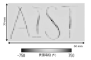
- FIG. 6 is a table showing the measurement conditions of the example.
- FIG. 7 is a graph showing the results of the example.
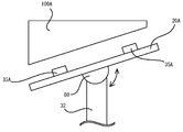
- FIG. 8 is a schematic diagram of a detection unit according to the second embodiment.
- FIG. 9 is a schematic diagram of a detection unit according to the third embodiment.
- FIG. 1 shows a schematic diagram of a static electricity distribution measuring apparatus according to this embodiment.
- the static electricity distribution measuring apparatus 1 includes a measurement target moving unit 10, a detection unit 20 disposed so as to face the measurement target moving unit 10 with a rectangular measurement target 100 interposed therebetween, and a detection The static electricity amount measuring unit 30 to which the unit 20 is attached, and the result display unit 40 that is a calculation unit connected to the measurement target moving unit 10 and the static electricity amount measuring unit 30 via the wiring 50, respectively.
- the measurement target moving unit 10 is fixed to a fixed object (not shown), and can hold the measurement target 100 via the measurement target holding unit 11.
- the measurement target moving unit 10 incorporates a motor (not shown) that can move the measurement target holding unit 11 in the A direction or the B direction, and the measurement target object 100 is moved via the measurement target holding unit 11. It can be moved in the A direction or the B direction.
- the measurement target moving unit 10 includes a movement distance detection unit (not shown), and can detect the distance and the number of times the measurement target 100 is moved in the A direction or the B direction. .
- the measurement target moving unit 10 is not particularly limited as long as it has such a function.
- the A direction or B direction in FIG. 1 may be a depth direction or a front direction.
- the result display unit 40 which is also a calculation unit, has a display unit 41 such as a display, and can display the electrostatic charge distribution on the surface of the measurement object 100 on the detection unit 20 side, as will be described later. ing.
- the change amount, the frequency, and the phase angle of the potential change detected by the detection unit 20 can be calculated, and the static electricity amount can be calculated based on at least one of them.
- the static electricity distribution on the surface of the measurement object 100 can be displayed.
- a personal computer or the like may be used.
- the method described in Patent Documents 1 and 2 can be used as a method for calculating the amount of static electricity from the change in potential, the amount of change in potential, the frequency and the phase angle, and the method for displaying the static electricity distribution. .
- the charge amount (electrostatic amount) Q of the portion of the measurement object 100 facing the sensor 21 described later can be calculated by the following equation.
- ⁇ V is the difference between the maximum potential and the minimum potential detected by the sensor 21 (potential difference)
- ⁇ is the dielectric constant between the sensor 21 and the portion of the measuring object 100 facing the sensor 21
- S is the sensor 21
- D is the distance between the upper surface of the detector 20 and the lower surface of the measurement object 100
- R is the amplitude of vibration.
- the static electricity distribution on the surface of the measurement object 100 is finally measured by calculating the amount of static electricity of each part of the measurement object 100 facing each sensor 21 using this equation. can do.
- the detected potential difference ⁇ V can be calculated by the following equation.
- a and b are predetermined constants.
- the potential difference ⁇ V detected by the sensor is expressed as a function of only the amplitude R. It can be seen that the potential difference ⁇ V increases as the amplitude R increases. Therefore, in the static electricity distribution measuring apparatus 1, when the static electricity amount is small, the static electricity amount can be detected with high accuracy by adjusting (increasing) the amplitude R.
- Whether the charge of each part of the measurement object 100 is positive or negative can be determined by considering the direction of the current flowing through the sensor 21 when the measurement object 100 is vibrated. For example, when the portion where the positive charge of the measurement object 100 is charged moves upward, the direction of the current is the same as the moving direction of the measurement object 100, but the negative charge is charged. When the moving part moves upward, the direction of the current is opposite to the moving direction of the measurement object 100. Therefore, the phase angle of the potential detected by the sensor 21 is shifted by 180 ° when positive and negative charges are detected. Therefore, by determining this, it is possible to distinguish whether the charge of the part of the measurement object 100 facing the sensor 21 is positive or negative.
- the wiring 50 is not particularly limited as long as it can transmit a signal between the components.
- FIG. 2 is a schematic cross-sectional view of the electrostatic quantity measuring unit 30.
- the static electricity amount measuring unit 30 includes a shaft 32 disposed inside the right side of the box-shaped housing 31, a vibration exciter 33 that is a vibration unit disposed below the shaft 32, and an excitation device.
- a distance adjustment unit 34 disposed below the vibrator 33 and a reference distance measurement unit 35 disposed on the upper left side of the housing 31 are provided. These arrangement
- positioning will not be specifically limited if each function can be exhibited.
- the reference distance measurement unit 35 is not particularly limited as long as the distance D between the lower surface of the measurement object 100 and the upper surface of the detection unit 20 and the amplitude R of the vibration exciter 33 can be measured.
- a laser displacement sensor or the like may be used.
- the distance adjusting unit 34 adjusts the position (height h) of the vibration exciter 33 based on the distance measured by the reference distance measuring unit 35, so that the lower surface of the measurement object 100 and the upper side of the detecting unit 20 are adjusted.
- the distance from the surface can be adjusted to a predetermined reference distance DS.
- the distance adjusting unit 34 is not particularly limited as long as the position (height h) of the vibration exciter 33 can be accurately adjusted.
- the vibration exciter 33 can vibrate the detection unit 20 in the vertical direction by vibrating the shaft 32 in the vertical direction.
- the vibrator 33 is not particularly limited as long as it can vibrate the detection unit 20 together with the shaft 32 at a predetermined cycle.
- the period (frequency) of the vibrator 33 is not particularly limited, but is preferably in the range of 10 Hz to 5 kHz, and particularly preferably in the range of 100 Hz to 1 kHz.
- the amplitude R of the vibrator 33 is not particularly limited, but is preferably in the range of 0.01 mm to 1 mm, and particularly preferably in the range of 0.05 mm to 0.5 mm.
- the shaft 32 is connected to the detection unit 20 through a hole 36 provided in the upper right portion of the housing 31.
- the shaft 32 is not particularly limited as long as it can hold the detection unit 20.
- the positional relationship among the upper part of the housing 31, the hole 36, and the detection unit 20 is not particularly limited.
- the electrostatic quantity measuring unit 30 further includes a lock-in amplifier (not shown) such as a Model 7210 manufactured by Signal Recovery, which is a measuring unit, and removes noise and the like from the signal detected by the detecting unit 20. It is possible to measure various signals simultaneously on multiple channels.
- the time constant of the lock-in amplifier is not particularly limited, but is preferably in the range of 0.1 ms to 1 s, particularly preferably in the range of 1 ms to 300 ms.
- FIG. 3 is a schematic view of the upper surface of the detection unit 20
- FIG. 4 is a schematic cross-sectional view of the detection unit 20 when viewed from the C-C 'direction shown in FIG.
- a plurality of sensors 21 are provided on the upper surface of the detection unit 20 so as to be arranged in two rows in a direction orthogonal to the moving direction A of the measurement object 100.
- the sensors 21 have a square shape and are arranged with a predetermined interval.
- the size of the sensor 21 is not particularly limited, but a size in the range of 0.1 mm ⁇ 0.1 mm to 5 mm ⁇ 5 mm is preferable, and a size in the range of 0.1 mm ⁇ 0.1 mm to 1 mm ⁇ 1 mm is preferable. The above is particularly preferable.
- the detection unit 20 By configuring the detection unit 20 in this way, all changes in the potential in the width direction of the measurement object 100 can be detected by a single measurement, and as a result, the static electricity amount distribution of the measurement object 100 can be quickly measured. can do.
- Each sensor 21 is connected via a connecting portion 24 to a conductive member 23 inserted in a detection portion main body 22 made of an insulator such as resin, and a signal relating to a change in potential detected by each sensor 21. Can be transmitted to the electrostatic quantity measuring unit 30 via a cable (not shown) connected to the conductive member 23. If the sensor 21 and the conductive member 23 are electrically connected, the connecting portion 24 may not be provided.
- an absorption part 25 is integrally provided around each sensor 21 so as to surround each sensor 21, and other than a part of the surface of the measurement object 100 facing each sensor 21.
- the electromagnetic influence from the part can be absorbed.
- each sensor 21 can mainly detect a change in potential from the portion of the measurement object 100 facing each other, and thus can measure the amount of static electricity at a more accurate position.
- the static electricity distribution measuring apparatus 1 can measure the static electricity distribution with higher spatial resolution.
- the senor 21 is not particularly limited as long as it can detect a change in potential, and may be, for example, a metal thin film.
- the absorbing portion 25 is not particularly limited as long as it can absorb electromagnetic influences, and may be a metal thin film or an electromagnetic wave absorbing sheet, for example.
- the conductive member 23 and the connection portion 24 are not particularly limited as long as they can transmit signals to the cable. Examples of the conductive member 23 include a copper wire, and examples of the connection portion 24 include solder. Etc.
- FIG. 5 is an operation flowchart of the static electricity distribution measuring apparatus 1.
- the reference distance measurement unit 35 measures the distance D between the lower surface of the measurement object 100 and the upper surface of the detection unit 20 (S1). . Thereafter, the magnitudes of the distance D and the reference distance DS + ⁇ are compared (S2). When the distance D is greater than the reference distance DS + ⁇ , the position (height h) of the vibration exciter 33 is increased by a predetermined height (S3), and the distance D is measured again.
- ⁇ is an allowable value of the predetermined reference distance DS, and the size thereof is not particularly limited, but is preferably in the range of 0.01 mm to 5 mm, and particularly preferably in the range of 0.05 mm to 1 mm.
- the distance D is less than or equal to the reference distance DS + ⁇
- the magnitudes of the distance D and the reference distance DS ⁇ are compared (S4).
- the distance D is smaller than the reference distance DS- ⁇
- the position (height h) of the vibration exciter 33 is lowered by a predetermined height (S5). Such an operation is repeated until the distance D is larger than DS ⁇ and smaller than DS + ⁇ .
- the vibrator 33 is driven (ON) (S6), and the reference distance measuring unit 35 measures the amplitude R of the vibrator 33 and transmits the amplitude R to the result display unit 40 (S7). ).
- the measurement object moving unit 10 moves the measurement object 100 in the A direction, and the movement distance L is transmitted to the result display unit 40 (S8).
- the movement distance L per movement when the measurement object 100 moves can be freely determined according to the size of the sensor 21 and the required resolution of electrostatic distribution.
- the same length as the side of the sensor in the same direction as the moving direction A (about 0.1 mm to 5 mm) is preferable. By using such a moving distance L, the static electricity distribution can be measured more accurately and quickly.
- the distance D between the lower surface of the measurement object 100 and the upper surface of the detection unit 20 is measured by the reference distance measurement unit 35 (S9). Thereafter, the magnitudes of the distance D and the reference distance DS + ⁇ are compared (S10). When the distance D is greater than the reference distance DS + ⁇ , the position (height h) of the vibration exciter 33 is increased by a predetermined height (S11), and the distance D is measured again.
- the distance D is less than or equal to the reference distance DS + ⁇
- the magnitudes of the distance D and the reference distance DS ⁇ are compared (S12). If the distance D is smaller than the reference distance DS- ⁇ , the position (height h) of the vibrator 33 is lowered by a predetermined height (S13).
- S9 to S13 can be omitted.
- the result display unit 40 displays information on the change in potential transmitted from the electrostatic quantity measuring unit 30, the moving distance L of the measuring object 100 per movement, the number of movements N of the measuring object 100, the amplitude R, and the reference distance. From the DS, the static electricity amount distribution of the measurement object 100 is calculated (S16). Then, the static electricity distribution of the measurement object 100 is displayed on the display unit 41.
- a database consisting of a large number of data relating to potential changes, reference distances, amplitudes, and the corresponding static electricity amounts is calibrated and created in advance, and the potential change amounts and reference distances obtained from the sensors 21. From the DS and the amplitude R, the amount of static electricity at that time is calculated. This amount of static electricity is the amount of static electricity in the portion of the measurement object 100 facing the sensor 21 when a change in potential is detected.
- the electrostatic distribution of the measurement object 100 can be measured with high accuracy and quickly.
- the arrangement length of the sensors 21 is configured to be slightly longer than the length (width of the measurement object) in the direction (width direction) orthogonal to the movement direction A of the measurement object 100.
- the length of the array of sensors 21 is not limited to this. When the length of the array of sensors 21 is shorter than the width of the measurement object, the static electricity distribution of the measurement object cannot be measured by a single measurement. It can be measured.
- the absorption part 25 is formed so as to surround the sensor 21, but it is not always necessary to form the absorption part so as to completely surround the sensor 21.
- the absorption part may be formed only in a part around the area 21 or the absorption part may not be formed. Compared to the case where the absorption part is formed so as to completely surround the sensor 21, the function of absorbing the electromagnetic influence from the part other than the part facing the sensor 21 is reduced, but the amount of static electricity is measured. I can.
- a rectangular object is used as the measurement object 100, but the shape of the measurement object 100 is not limited to this.
- the shape of the measurement object 100 may be, for example, a cylindrical shape or a film shape manufactured by a roll-to-roll method.
- the potential change is detected while repeating the movement / stop of the measurement object 100, but the operation of the electrostatic distribution measuring apparatus 1 is not limited to this.
- a change in potential may be detected for each predetermined movement distance l while moving the measurement object 100 at a constant speed. By operating in this way, the static electricity distribution of the measurement object can be measured more quickly.
- the moving speed of the measuring object 100 is not particularly limited, but is preferably in the range of 0.1 mm / s to 200 mm / s, particularly preferably in the range of 1 to 20 mm / s.
- the moving distance l is not particularly limited, and is preferably in the range of 0.01 mm to 5 mm, particularly preferably in the range of 0.1 mm to 1 mm.
- the static electricity distribution measuring device 1 was comprised so that the result display part 40 might serve as a calculation part, this invention is not limited to this.
- the static electricity distribution measuring apparatus may be configured using a separate personal computer or the like as the calculation unit.
- a static electricity distribution measuring apparatus having a detection unit in which they were arranged in one row (30 pieces arranged per row) at 1 mm intervals was configured.
- the detection unit 20 can only move up and down in parallel, but the present invention is not limited to this.
- a rotation unit 60 is provided between the detection unit 20A and the shaft 32, and in a direction orthogonal to the moving direction of the measurement object 100A (the direction moving in the direction perpendicular to the paper surface), You may enable it to incline (rotate) a detection part.
- FIG. 8 is a schematic diagram of the detection unit 20A according to the present embodiment.
- the detection unit 20A can be rotated so that the distance between the measurement target 100A and each sensor 21 is equal to the shape (thickness) of the measurement target 100A. it can.
- the static electricity distribution can be measured with high accuracy and quickly.
- the rotation unit 60 is not particularly limited as long as it can rotate the detection unit 20A based on the measurement results of the two reference distance measurement units 35A provided on the upper surface of the detection unit 20A.
- a rotation part may be provided between a measurement object and a measurement object holding part (end part by the side of the measurement object of a measurement object holding part), or even if these two rotation parts are combined. Good.
- the measurement object or the measurement object and the detection unit can be rotated so that the distance between the measurement object and each sensor is equal. Therefore, the electrostatic distribution measurement device of the present embodiment The same effect can be obtained. (Embodiment 3)
- the detection unit is configured such that each sensor 21 is flat (on the same plane), but the present invention is not limited to this.
- the detection unit 20B may be configured so that each sensor 21 can move up and down independently.
- FIG. 9 is a schematic diagram of the detection unit 20B according to the present embodiment.
- the detection unit 20B for example, a plurality of expansion / contraction parts 27 provided on a base 28 such as a resin, and sensors 21 connected to the respective expansion / contraction parts 27 via an insulator 29 such as a resin, respectively. And can be configured.
- the expansion / contraction part 27 is not particularly limited as long as it can expand and contract, and examples thereof include an actuator.
- a reference distance measurement unit (not shown) that measures the distance to the measurement object is provided in the vicinity of each sensor 21, and the distance becomes the reference distance DS according to the distance measured by the reference distance measurement unit. Thus, it is controlled by an actuator.
- each sensor 21 can be adjusted so that the distance from the surface of the measurement object is within the reference distance DS ⁇ ⁇ .
- the static electricity distribution can be quickly measured with high accuracy.
- the distance adjustment part 34 has been arrange
- the static electricity distribution measuring device which concerns on this invention is not limited to this.
- the distance adjustment unit is arranged above the measurement target holding unit 11 so that the measurement target holding unit 11 can be moved and the measurement target holding unit 11 or the measurement target moving unit 10 can be moved in the vertical direction.
- the detection unit is configured so that the sensors 21 are arranged in a direction orthogonal to the moving direction of the measurement object 100.
- the electrostatic distribution measurement apparatus according to the present invention is not limited to this.
- the detection unit may be configured such that the sensor 21 is arranged in a direction other than the direction orthogonal to the moving direction of the measurement object 100. Even if comprised in this way, the effect similar to the static electricity distribution measuring apparatus of Embodiment 1 is acquired.
- the sensors 21 are provided in two rows on the upper surface of the detection unit 20, but the static electricity distribution measuring apparatus according to the present invention is not limited to this.
- the sensors may be provided in a single row on the upper surface of the detection unit 20, or may be provided in a row of three rows or more. As the number of columns increases, the portion where the change in potential can be detected increases, so that the static electricity amount distribution of the measurement object can be measured earlier.
- the static electricity distribution measuring apparatus which concerns on this invention is not limited to this.
- the measurement object may be fixed and the electrostatic distribution measurement device may be configured to measure the static electricity distribution of the measurement object while the detection unit moves, or the measurement object and the detection unit can be moved respectively. It may be configured. Even if comprised in this way, the effect similar to the static electricity distribution measuring apparatus mentioned above is acquired.
- the detection unit is configured to vibrate, but the static electricity distribution measuring apparatus according to the present invention is not limited to this.
- the detection unit may be fixed, and the measurement target may be vibrated by arranging a vibrator between the fixed object and the measurement target holding unit 11, or the detection unit and the measurement target may be vibrated together.
- You may comprise an electrostatic distribution measuring apparatus. Even if comprised in this way, the effect similar to the static electricity distribution measuring apparatus mentioned above is acquired.
- the above-described static electricity distribution measuring device is disposed in a sealed space connected to a vacuum pump or the like, and is exhausted by a vacuum pump or the like so that the measurement object and the detection unit are placed in an atmosphere of 100 atm or less.
- a distribution measuring device may be configured. With this configuration, gas (oxygen or the like) or moisture that facilitates gas discharge can be reduced, so that the amount of static electricity on the surface of the measurement object can be measured with higher accuracy.
- the static electricity distribution measurement apparatus is configured such that the measurement target moving unit is arranged above and the detection unit is arranged below, but the present invention is not limited to this.
- the static electricity distribution measurement device may be configured such that the measurement target moving unit is disposed below and the detection unit is disposed above.
Landscapes
- Physics & Mathematics (AREA)
- General Physics & Mathematics (AREA)
- Measurement Of Length, Angles, Or The Like Using Electric Or Magnetic Means (AREA)
Abstract
【課題】従来の静電気分布計測装置では、広範囲の静電気量を高空間分解能・広範囲でかつ素早く分布計測することができないという課題があった。 【解決手段】帯電した計測対象物100の表面に沿って相対的に移動して、計測対象物の表面との距離を変化させることにより生じる電位の変化を検出するセンサが表面に複数設けられた検出部20と、計測対象物の表面と検出部の表面との距離を測定する基準距離測定部と、その距離が予め定められた基準距離になるように調整する距離調整部と、所定の周期で計測対象物の表面と検出部の表面との距離を変化させる振動部と具備する。
Description
本発明は、半導体製造、電子・電気機器製造、精密機械製造、輸送機械製造、化学品製造、繊維製造、セラミックス製造、薬品製造および食品製造などの様々な製造現場において、製造工程において用いられる部品や、金属や絶縁体を含む製品における静電気の帯電量分布を計測する静電気分布計測装置に関する。
日本には、半導体製造、電子・電気機器製造、精密機械製造、輸送機械製造、化学品製造、繊維製造、セラミックス製造、薬品製造および食品製造など、産業の根幹を支える様々な製造業を営む企業が多数存在している。このような製造業における実際の製造を受け持つ工場においては、多くの部品が生産ラインを流れながら、自動工程あるいは人為工程で製品が組み立てられている。
ここで、製品を構成する部品に不具合や不良があったり、製造工程に不具合や不良があったりすると、当然ながら製造される製品も不具合や不良品となり、製造の歩留まりが下がる問題がある。あるいは部品に問題がなくとも、製造後の製品に種々の理由で不具合や不良が生じることもある。前者および後者のいずれにも係る問題として、自動化された製造工程において、各工程での動作不良が生じると、製造速度(製造効率)が下がったり、製品の製造歩留まりが下がったりする問題がある。
従来は大企業を中心に、研究、開発、設計、製造、品質管理、販売までの一連の流れが垂直統合的に行われていることが多かった。このような垂直統合型の企業においては、製造現場で生じうる製造品(完成品や半完成品)の品質不足や歩留まり低下に関する開発や設計での対応は、同一企業内部でフィードバック、フィードフォワードしやすい環境にあった。
一方で、近年においては、同一企業において製造コストの問題から製造部門(すなわち製造工場)が子会社化されたり、受託製造だけを行う製造企業が現れたりしている。同様に、研究・開発だけを行って、製造を行わないファブレス企業なども、電気分野、情報通信分野などを中心に興隆している。
このように、現在の製造業においては、開発や設計を行う領域と実際の製造を行う領域とに、物理的、時間的、技術的、人的な乖離があることが多くなってきている。このような乖離がある場合には、製造現場で生じる品質不足や歩留まり劣化について、製造現場と開発現場との間で、フィードバックやフィードフォワードすることが困難である。この困難によって、日本国の製造業(製造のみを請け負う受託製造会社、製造子会社、ファブレス企業などを含む)における製造力が低下している懸念がある。
製造現場における品質や歩留まりの劣化原因には様々なものがある。設計と製造の容易性、製造現場の熟練度、製造工程のフロー、製造設備、人的スキルなどの不可避の原因もあるが、見落とされがちな原因の一つは、静電気である。すなわち、このような部品、製品あるいは製造工程での不具合や不良の原因には、様々なものがあるが、原因の一つとして静電気が考えられる。
製造工場においては、このような静電気による部品、製品、製造工程などへの悪影響を考慮して、除電、工場の建物、床、壁などの静電気防止、作業者の服装の静電気防止の工夫など、静電気が部品、製品、製造工程へ影響を及ぼさない工夫がなされている。具体的には、床面、壁、コンベアラインなどを、作業開始前に除電したり、除電用のアースが設けられたりして、製造工程で用いられる部品や製品が静電気を帯びないように工夫がなされている。
また、製造工場においては、製造工程で用いられる部品を予め除電するなどの工夫も行われている。同様に、作業者も、除電を行ってから作業を開始するという工夫も行っている。
このように、製造工場においては、静電気の悪影響を抑える工夫が様々に施されている。このような工夫にもかかわらず、製造工程で用いられる部品や製品が、静電気を帯びてしまう問題は完全に解決されていない。例えば、製造工場で製造される電子機器、精密機器などは、低消費電力化が進んでいる。低消費電力化に伴い、これら電子機器や精密機器の製造に用いられる部品は、静電気耐性能力も低下してしまう。このため、これら電子機器や精密機器の製造に用いられる部品は、静電気を帯びて、簡単に故障してしまうことも多い。
このような電子機器や精密機器の製造に用いられる部品には、様々な種類のものがある。例えば、樹脂やビニールで作られた部品(コネクタ、画面用カバー、筐体など)も、数多く使用される。これらの部品は、一定の大きさを有しており、静電気を帯びると、予測不能な挙動を生じることがある。
例えば、複数の部品が、コンベアラインを流れて一定の位置に配置される工程に入ったり、画像処理による外観検査の工程に入ったりする。このような工程においては、コンベアラインに投入された複数の部品が、投入間隔を保ってコンベアラインを流れることが望まれる。
しかしながら、このような部品が静電気を帯びていると、コンベアラインにおいて、部品同士が静電気によって近づいたり反発して遠ざかったりなどの挙動が生じる。場合によっては、隣接する部品同士がくっついたりする。このような挙動が生じると、上述の配置工程や外観検査工程において、適切な実施処理ができなくなってしまい、良品にもかかわらず、不良品と自動判別されることがある。
配置工程や外観検査工程において、このような部品の予測不能な挙動が生じてしまうと、一旦、コンベアラインを停止させる必要がある。この挙動は、静電気に起因しているとの予測は付くが、対策としては、コンベアラインや工程上の機器、さらにはコンベアラインに投入される部品の全てに、除電を施すしかない。このような除電作業によって、コンベアラインが停止されると、製造工場においては、大きな損害が生じる。除電作業の間(場合によっては半日や1日を要する)、製造作業が停止するからである。
このような部品が上述のような挙動を生じさせるのは、静電気が原因であろうことは分かっているが、実際の挙動に至るメカニズムはほとんど解明されていない。特に、部品同士が近づいたり遠ざかったりなどの、異なる挙動を示すこともあれば、全く挙動を示さないこともある。このため、部品に帯電している(と考えられる)静電気が、部品においてどのように分布しているのかが分からないことには、挙動に至るメカニズムの解明が困難である。メカニズムの解明が困難であれば、当然に上述のような挙動を防止する対策案の検討もできない。
また、携帯電話機やスマートフォンなどの画面上に取り付けられる樹脂やビニールなどで形成されるカバーは、その材質や面積の大きさから、静電気を帯びやすい。このような部品が、電子機器や精密機器の組立工程で用いられる場合に、やはり部品が静電気を帯びていると、静電気によって設置位置が勝手にずれたりしてしまうことがある。こうなると当然に組み立てられる機器は、不良品となってしまう。
この場合も、部品が静電気を帯びていることが原因であることは予想がつくが、挙動と静電気帯電との関連性が分からない。この関連性が分からないと、問題の解決を図ることができない。すなわち、部品等に、どのような静電気の帯電が起きているかを、明確に把握することが、製造工程で生じる問題解決の前提となる。言い換えれば、部品などにおいて、静電気がどのような分布で帯電しているかを確認できることが、部品の挙動解明の前提条件である。
さらに、プリンタのように静電気を利用する機器においては、静電気帯電を利用する部品の静電気分布が確認されることが必要である。
このように、製造工程等における静電気に起因すると思われる様々な問題を解決する前提や、静電気を利用する部品の性能や特性を確認する前提において、部品等の静電気の帯電量分布を正確かつ素早く計測できることが望まれている。
このような静電気の帯電量を計測するための装置として、表面電位計(Surface electrometer)、静電気力顕微鏡(Electrostatic Force Microscope)または計測対象物に与えられた振動によって生じる仮想電磁波を電位の変化として計測することにより静電気の帯電量を算出する静電気量計測装置等が提案されている(例えば、特許文献1および2参照)。
しかしながら、表面電位計(静電誘導型・振動容量型)では、狭い面積に限定して静電気の帯電量を計測することしかできない(1mm以下の空間分解能で静電気量を計測できない)という問題点があった。また、表面電位計では、チョッピング(chopping)や振動機構が必須のためにセンサを小型化することができず、小型のセンサを配列化(アレイ化)することができない。その結果、一度の計測で、高空間分解能(1mm程度)で静電気の帯電量分布を計測することができないという問題点があった。したがって、表面電位計を用いて1mm程度の空間分解能でかつ広範囲(数cm2)の静電気の帯電量を計測するには、表面電位計でその範囲を1点1点走査させる必要があるため、静電気の帯電量分布を計測するには時間がかかるという問題点があった。
また、静電気顕微鏡では、超高空間分解能(1μmオーダー)で計測することはできるが、計測できる範囲が小さい(2mm2程度)という問題点があった。さらに、静電気顕微鏡では、構成要素であるカンチレバーを高精度で制御する必要があるため、表面電位計と同様に、センサを配列化(アレイ化)することができず、一度の計測で静電気の帯電量分布を計測することができないという問題点があった。したがって、静電気顕微鏡を用いて静電気の帯電量分布を計測するには、静電気顕微鏡でその範囲を1点1点走査させる必要があるため、静電気の帯電量分布を計測するには時間がかかるという問題点があった。
一方、特許文献1および2で開示されている静電気量計測装置では、高い精度で静電気の帯電量を計測することはできるが、1mm程度の高空間分解能で静電気の帯電量を計測するには、計測対象物を局所的に振動させる必要があることから、計測する全ての範囲を局所的に振動させる必要がある。その結果、静電気の帯電量分布を計測するには時間がかかるという問題点があった。
本発明は、上述した事情に鑑み、計測対象物の静電気の帯電量分布を高空間分解能・広範囲でかつ素早く計測できる静電気分布計測装置を提供することを目的とする。
本発明の発明者は、上述した問題点に関して鋭意研究を続けた結果、以下のような構造を有する画期的な静電気分布計測装置を見出した。
上記課題を解決する本発明の第1の態様は、帯電した計測対象物の表面に沿って相対的に移動して、計測対象物の表面との距離を変化させることにより生じる電位の変化を検出するセンサが表面に複数設けられた検出部と、計測対象物の表面と検出部の表面との距離を測定する基準距離測定部と、基準距離測定部により測定された距離が予め定められた基準距離になるように、計測対象物の表面と前記検出部の表面との距離を調整する距離調整部と、所定の周期で計測対象物の表面と検出部の表面との距離を変化させる振動部と、検出部が検出した電位の変化量、周波数および位相角の少なくとも1つを計測する計測部と、検出部に対する計測対象物の相対的な移動距離と、計測部の計測結果に基づいて、測定対象物の表面の静電気量を算出する算出部と、を具備することを特徴とする静電気分布計測装置にある。
ここで、「相対的に移動して」とは、計測対象物を固定して検出部を移動させる場合と、検出部を固定して計測対象物を移動させる場合、またはその両方を組み合わせた場合を意味する。また、「電位の変化量」とは、計測対象物の帯電した部分と検出部との相対的な距離が周期的に変化することに伴って、センサによって検出される最大電位と最小電位の差(電位差)をいう。「電位の周波数」とは、計測対象物の帯電した部分と検出部との相対的な距離が周期的に変化することに伴って、センサによって検出される電位の周波数をいう。「電位の位相角」とは、計測対象物の帯電した部分と検出部との相対的な距離が周期的に変化することに伴って、計測対象物の帯電した部分と検出部との相対的な距離の周期と、センサによって検出される電位の周波数との位相のズレをいう。
かかる第1の態様では、相対的に移動する計測対象物の表面を、動作を止めることなく連続で走査しながら、センサが対向する計測対象物の狭領域の静電気量を検出することができるので、計測対象物の静電気量を高空間分解能・広範囲でかつ素早く計測することができる。すなわち、計測対象物を相対的に移動させながら、その表面の静電気量を、その瞬間に対向する位置にあるセンサで検出することができるので、計測対象物の表面の静電気量を高空間分解能・広範囲でかつ素早く計測することができる。ここで、「静電気量」とは、表面電位、電荷量、電気的極性をいう。
本発明の第2の態様は、センサは、計測対象物の移動方向と交差する方向に、列状に複数配置されていることを特徴とする第1の態様に記載の静電気分布計測装置にある。
かかる第2の態様では、列状に配置された複数のセンサにより、計測対象物の表面の所定の範囲の電位の変化を一度に計測することができるので、より広範囲の計測対象物の表面の静電気の帯電量分布をより素早く計測することができる。
本発明の第3の態様は、計測対象物の表面に対して検出部が平行になるように、計測対象物および検出部の少なくとも何れか一方を回動できる回動部が設けられていることを特徴とする第1または第2の態様に記載の静電気分布計測装置にある。
かかる第3の態様では、計測対象物の形状(厚み)に合わせて、計測対象物とセンサとの距離が等しくなるように、計測対象物および検出部の少なくとも何れか一方を回動させることができるので、形状が変わる計測対象物であっても、その表面の静電気量を高い精度でかつ素早く計測することができる。
本発明の第4の態様は、センサが、計測対象物の方向にそれぞれ移動できることを特徴とする第1~3の態様の何れかに記載の静電気分布計測装置にある。
かかる第4の態様では、計測対象物の形状に合わせて各センサを移動させることにより、センサごとに計測対象物の表面との距離が基準距離となるように調整することができる。その結果、第4の態様に係る静電気分布計測装置は、複雑な形状の計測対象物であっても、その表面の静電気の帯電量分布を高い精度でかつ素早く計測することができる。
本発明の第5の態様は、センサの周囲の少なくとも一部に、電磁気的影響を吸収する吸収部が設けられていることを特徴とする第1~4の態様の何れかに記載の静電気分布計測装置にある。
ここで、「電磁気的影響」とは、電界、磁界、ノイズなどのセンサが検出する電位の変化に影響を与えるものをいう。
かかる第5の態様では、センサに対向している部分以外の部分から放射される電磁気的影響をそのセンサの周囲に位置する吸収部が吸収するので、センサは、対向している部分からの電位の変化を主に検出することができる。その結果、より正確な位置かつ狭面積(高空間分解能)で計測対象物の静電気の帯電量分布を計測することができる。
本発明の第6の態様は、計測対象物および検出部が100atm以下の雰囲気中にあることを特徴とする第1~5の態様の何れかに記載の静電気分布計測装置にある。
かかる第6の態様では、気体放電し易くするガス(酸素等)や水分を減少させることができるので、計測対象物の表面の静電気量をより高い精度で計測することができる。
以下に添付図面を参照して、本発明に係る静電気分布計測装置の実施形態を説明する。なお、本発明は、以下の実施形態に限定されるものではない。
(実施形態1)
(実施形態1)
図1に、本実施形態に係る静電気分布計測装置の概略図を示す。図1に示すように、静電気分布計測装置1は、計測対象移動部10と、計測対象移動部10と矩形状の計測対象物100を挟んで対向するように配置された検出部20と、検出部20が取り付けられた静電気量測定部30と、計測対象移動部10と静電気量測定部30のそれぞれに配線50を介して接続された算出部である結果表示部40とで構成されている。
計測対象移動部10は、固定物(図示しない)に固定されており、計測対象保持部11を介して計測対象物100を保持することができるようになっている。また、計測対象移動部10は、計測対象保持部11をA方向またはB方向に移動させることができるモータ(図示しない)を内蔵しており、計測対象保持部11を介して計測対象物100をA方向またはB方向に移動させることができるようになっている。さらに、計測対象移動部10は、移動距離検出部(図示しない)を有し、計測対象物100をA方向またはB方向に移動させた距離およびその回数を検出することができるようになっている。計測対象移動部10としては、このような機能を有するものであれば特に限定されない。図1のA方向またはB方向は、奥行方向または手前方向であってもよい。
算出部でもある結果表示部40は、ディスプレイ等の表示部41を有しており、後述するように計測対象物100の検出部20側の表面の静電気量分布を表示することができるようになっている。結果表示部40としては、検出部20によって検出された電位の変化の変化量、周波数および位相角を算出することができると共にそれらの少なくとも1つに基づいて静電気量を算出することができ、さらに計測対象物100の表面の静電気分布を表示することができるものであれば特に限定されず、例えばパーソナルコンピュータ等であってもよい。なお、電位の変化および電位の変化の変化量、周波数および位相角から静電気量を算出する方法および静電気分布の表示方法については、特許文献1および2に記載されている方法等を用いることができる。
例えば、後述するセンサ21に対向する計測対象物100の部分の電荷量(静電気量)Qは、次式により算出することができる。

ここで、ΔVはセンサ21によって検出される最大電位と最小電位の差(電位差)、εはセンサ21とそのセンサ21に対向する計測対象物100の部分との間の誘電率、Sはセンサ21の面積、Dは検出部20の上側表面と計測対象物100の下側表面との距離、Rは振動の振幅である。
計測対象物100を移動させながら、この式を用いて各センサ21に対向する計測対象物100の各部分の静電気量を算出することによって、最終的に計測対象物100の表面の静電気分布を測定することができる。
なお、電荷量Q、誘電率ε、センサ21の面積S、距離Dが一定の場合、検出される電位差ΔVは次式により算出することができる。
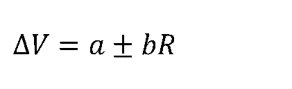
この式によれば、センサで検出される電位差ΔVは、振幅Rのみの関数で表される。そして、振幅Rが大きくなるにつれて、電位差ΔVも大きくなることが分かる。したがって、静電気分布計測装置1では、静電気量が小さい場合には、振幅Rを調整(大きく)することによって、その静電気量を高精度で検出することができる。
また、計測対象物100の各部分の電荷が正か負かについては、計測対象物100を振動させた時のセンサ21を流れる電流の向きを考慮することで、判断することができる。例えば、計測対象物100の正の電荷が帯電している部分が上に動いたときは、その電流の向きは計測対象物100の移動方向と同じ方向になるが、負の電荷が帯電している部分が上に動いたときは、その電流の向きは計測対象物100の移動方向と逆の方向になる。そのため、センサ21で検出される電位の位相角が、正と負の電荷を検出したときに180°ずれることになる。したがって、これを判別することで、センサ21に対向する計測対象物100の部分の電荷が正か負かを区別することができる。
配線50は、各構成部間で信号を伝達できるものであれば特に限定されない。
次に、図2を用いて、静電気量測定部30について説明する。図2は静電気量測定部30の断面概略図である。図2に示すように、静電気量測定部30は、箱状の筐体31の右側内部に配置されたシャフト32と、シャフト32の下方に配置された振動部である加振機33と、加振機33の下方に配置された距離調整部34と、筐体31の左側上部に配置された基準距離計測部35とを有している。これらの配置は、それぞれの機能を発揮できるのであれば、特に限定されない。
基準距離計測部35は、計測対象物100の下側表面と検出部20の上側表面との距離Dと、加振機33の振幅Rを計測することができるものであれば特に限定されず、例えばレーザー変位センサ等であってもよい。
距離調整部34は、基準距離計測部35によって計測された距離に基づいて加振機33の位置(高さh)を調整することにより、計測対象物100の下側表面と検出部20の上側表面との距離が予め定められた基準距離DSになるように調整することができるようになっている。距離調整部34としては、加振機33の位置(高さh)を正確に調整することができるものであれば特に限定されない。
加振機33は、シャフト32を上下方向に振動させることにより、検出部20を上下方向に振動させることができるようになっている。加振機33としては、所定の周期でシャフト32と共に検出部20を振動させることができるものであれば特に限定されない。また、加振機33の周期(振動数)は特に限定されないが、10Hz~5kHzの範囲が好ましく、100Hz~1kHzの範囲が特に好ましい。さらに、加振機33の振幅Rも特に限定されないが、0.01mm~1mmの範囲が好ましく、0.05mm~0.5mmの範囲が特に好ましい。
シャフト32は、筐体31の右側上部に設けられた孔36を通って検出部20に接続されている。シャフト32としては、検出部20を保持することができるものであれば特に限定されない。また筐体31の上部と孔36と検出部20との位置関係は、特に限定されない。
また、静電気量測定部30は、計測部である例えばSignal Recovery社製Model7210等のロックインアンプ(図示しない)をさらに有しており、検出部20で検出された信号からノイズ等を取り除き、微小な信号を多チャンネルで同時に測定することができるようになっている。ロックインアンプの時定数は特に限定されないが、0.1ms~1sの範囲が好ましく、1ms~300msの範囲が特に好ましい。
さらに、図3および図4を用いて、検出部20について説明する。図3は検出部20の上側表面の概略図であり、図4は図3に示すC-C’方向から見た際の検出部20の概略断面図である。図3および図4に示すように、検出部20の上側表面には、センサ21が、計測対象物100の移動方向Aに対して直交方向に2列に配列するように複数設けられている。センサ21は、正方形状をしており、所定の間隔を空けて配列されている。ここで、センサ21の大きさは特に限定されないが、0.1mm×0.1mm~5mm×5mmの範囲の大きさのものが好ましく、0.1mm×0.1mm~1mm×1mmの範囲の大きさのものが特に好ましい。
このように検出部20を構成することにより、一度の計測で、計測対象物100の幅方向の電位の変化をすべて検出することができるので、結果として計測対象物100の静電気量分布を素早く計測することができる。
各センサ21は、樹脂等の絶縁体で構成された検出部本体22内に挿入された導電部材23と接続部24を介して接続されており、各センサ21により検出された電位の変化に関する信号を導電部材23に接続されたケーブル(図示しない)を介して静電気量測定部30に送信できるようになっている。なお、センサ21と導電部材23とが電気的に接続されていれば、接続部24はなくてもよい。
また、各センサ21の周囲には、各センサ21の周囲を囲むように吸収部25が一体的に設けられており、計測対象物100の表面のうち、各センサ21に対向している部分以外の部分からの電磁気的影響を吸収することができるようになっている。したがって、各センサ21は、計測対象物100の対向している部分からの電位の変化を主に検出することができるので、より正確な位置の静電気量を計測することができる。その結果、静電気分布計測装置1は、より高い空間分解能で静電気分布を計測することができる。
ここで、センサ21は電位の変化を検出することができるものであれば特に限定されず、例えば金属の薄膜であってもよい。また、吸収部25も電磁気的影響を吸収することができるものであれば特に限定されず、例えば金属の薄膜や電磁波吸収シートであってもよい。さらに、導電部材23および接続部24も信号をケーブルに伝えることができるものであれば特に限定されず、導電部材23としては例えば銅線などが挙げられ、接続部24としては例えば半田(solder)などが挙げられる。
次に、静電気分布計測装置1の動作について説明する。図5は、静電気分布計測装置1の動作フローチャートである。
図5に示すように、静電気分布計測装置1を起動させると、まず基準距離計測部35によって計測対象物100の下側表面と検出部20の上側表面との距離Dが計測(S1)される。その後、距離Dと基準距離DS+αとの大きさが比較される(S2)。そして、距離Dが基準距離DS+αよりも大きい場合には、加振機33の位置(高さh)が所定の高さの分だけ上げられ(S3)、再度距離Dが計測される。ここで、αは予め定めておく基準距離DSの許容値であり、その大きさは特に限定されないが、0.01mm~5mmの範囲が好ましく、0.05mm~1mmの範囲が特に好ましい。
一方、距離Dが基準距離DS+α以下の場合には、距離Dと基準距離DS-αとの大きさが比較される(S4)。そして、距離Dが基準距離DS-αよりも小さい場合には、加振機33の位置(高さh)が所定の高さの分だけ下げられる(S5)。そして、このような操作が、距離Dが、DS-αよりも大きく、DS+αよりも小さくなるまで繰り返される。
次に、加振機33を駆動(ON)させ(S6)、基準距離計測部35によって加振機33の振幅Rが計測されると共に、その振幅Rが結果表示部40に送信される(S7)。その後、計測対象移動部10によって計測対象物100がA方向に移動すると共に、その移動距離Lが結果表示部40に送信される(S8)。ここで、計測対象物100が移動する際の1回当たりの移動距離Lは、センサ21の大きさおよび必要とする静電気分布の解像度に応じて自由に定めることができるが、計測対象物100の移動方向Aと同じ方向のセンサの辺の長さと同じ長さ(0.1mm~5mm程度)が好ましい。このような移動距離Lとすることにより、より正確にかつ素早く静電気分布を計測することができる。
さらに、基準距離計測部35によって計測対象物100の下側表面と検出部20の上側表面との距離Dが計測される(S9)。その後、距離Dと基準距離DS+αとの大きさが比較される(S10)。そして、距離Dが基準距離DS+αよりも大きい場合には、加振機33の位置(高さh)が所定の高さの分だけ上げられ(S11)、再度距離Dが計測される。
一方、距離Dが基準距離DS+α以下の場合には、距離Dと基準距離DS-αとの大きさが比較される(S12)。そして、距離Dが基準距離DS-αよりも小さい場合には、加振機33の位置(高さh)が所定の高さの分だけ下げられる(S13)。
このような操作が、距離Dが、DS-αよりも大きく、DS+αよりも小さくなるまで繰り返され、距離Dがこれらの条件を満たすと、計測対象物100のセンサ21に対向する部分の電位の変化が検出され、その情報(電位の変化量・周波数・位相角)が静電気量測定部30に送信される(S14)。そして、上述したS8~S14の操作が、計測対象物100の全面の電位の変化が測定されるまで繰り返される(S15)。
なお、計測対象物100の下側表面と検出部20の上側表面との距離が一定と考えることができる場合には、S9~S13を省略することができる。
その後、結果表示部40が、静電気量測定部30から送信された電位の変化の情報、計測対象物100の1回当たりの移動距離L、計測対象物100の移動回数N、振幅Rおよび基準距離DSから、計測対象物100の静電気量分布を算出する(S16)。そして、表示部41に、計測対象物100の静電気分布が表示される。
具体的には、電位の変化と基準距離と振幅とそれらに対応する静電気量に関する多数のデータからなるデータベースを予め校正・作成しておき、各センサ21から得られた電位の変化量と基準距離DSと振幅Rから、その時の静電気量を算出する。この静電気量は、電位の変化を検出した時に、そのセンサ21に対向する計測対象物100の部分の静電気量となる。
したがって、計測対象物100の幅方向に対する各センサ21の相対位置を予め計測しておけば、各センサ21から得られた電位の変化に関する情報(電位の変化量・周波数・位相角)、計測対象物100の1回当たりの移動距離L、計測対象物100の移動回数N、振幅Rおよび基準距離DSより、計測対象物100の静電気分布を、高い精度でかつ素早く計測することができる。
なお、本実施形態では、センサ21の配列の長さが計測対象物100の移動方向Aに直交する方向(幅方向)の長さ(計測対象物の幅)より少し長くなるように構成したが、センサ21の配列の長さはこれに限定されない。センサ21の配列の長さが、計測対象物の幅より短い場合には、一回の測定では計測対象物の静電気分布を計測できないが、複数回計測することにより、計測対象物の静電気分布を計測することができる。
また、本実施形態では、センサ21の周囲を囲むように吸収部25が形成されていたが、必ずしもセンサ21を完全に囲むように吸収部を形成する必要はなく、例えば右側一辺のようにセンサ21の周囲の一部だけに吸収部を形成してもよいし、吸収部を形成しなくてもよい。センサ21を完全に囲むように吸収部を形成した場合と比較して、センサ21に対向している部分以外の部分からの電磁気的影響を吸収する機能は低下するが、静電気量を計測することはできる。
さらに、本実施形態では、計測対象物100として矩形状のものを用いたが、計測対象物100の形状はこれに限定されない。計測対象物100の形状としては、例えば円柱状やロールtoロール方式で製造されるフィルム状のものであってもよい。
また、本実施形態では、計測対象物100の移動・停止を繰り返しながら電位の変化を検出するようにしたが、静電気分布計測装置1の動作はこれに限定されない。たとえば、計測対象物100を一定の速度で移動させながら、所定の移動距離lごとに電位の変化を検出するようにしてもよい。このように動作させることにより、より早く計測対象物の静電気分布を計測することができる。
なお、この場合の計測対象物100の移動速度は特に限定されないが、0.1mm/s~200mm/sの範囲が好ましく、1~20mm/sの範囲が特に好ましい。また、移動距離lも特に限定されず、0.01mm~5mmの範囲が好ましく、0.1mm~1mmの範囲が特に好ましい。
また、本実施形態では、結果表示部40が算出部を兼ねるように静電気分布計測装置1を構成したが、本発明はこれに限定さない。たとえば、算出部として、別個のパーソナルコンピュータ等を用いて静電気分布計測装置を構成してもよい。
(実施例)
(実施例)
プリント基板にパターニングすることで作製された銅箔製のセンサ21を用い、それらが1mm間隔で1列(1列当たり30個配置)配置された検出部を有する静電気分布計測装置を構成した。
そして、30mm×60mmで厚さ1mmの塩化ビニールのフィルムに、「AIST」という文字を描くように金属を接触させた後、このフィルムの静電気分布を、図6に示す条件で静電気分布計測装置を用いて計測した。その計測結果のグラフを図7に示す。
図7に示すように、このフィルムが「AIST」という文字状に帯電していることが分かった。
(実施形態2)
(実施形態2)
実施形態1に係る静電気分布計測装置では、検出部20は上下に平行移動することしかできなかったが、本発明はこれに限定されない。例えば、図8に示すように、検出部20Aとシャフト32との間に回動部60を設け、計測対象物100Aの移動方向(紙面に対し垂直方向に移動する方向)に直交する方向に、検出部を傾斜(回動)できるようにしてもよい。図8は、本実施形態に係る検出部20Aの概略図である。このような回動部60を設けることにより、計測対象物100Aの形状(厚み)に合わせて、計測対象物100Aと各センサ21との距離が等しくなるように検出部20Aを回動させることができる。その結果、表面の形状(傾き)が変わる計測対象物100Aであっても、静電気分布を、高い精度でかつ素早く計測することができる。
なお、回動部60としては、検出部20Aの上側表面に設けられた2つの基準距離計測部35Aの計測結果に基づいて検出部20Aを回動させることができるものであれば特に限定されない。
また、回動部は、測定対象物と計測対象保持部との間(計測対象保持部の測定対象物側の端部)に設けられてもよいし、これら2つの回動部を組み合わせてもよい。このように構成することにより、計測対象物と各センサとの距離が等しくなるように計測対象物、または計測対象物および検出部を回動させることができるので、本実施形態の静電気分布計測装置と同様の効果が得られる。
(実施形態3)
(実施形態3)
実施形態1および2に係る静電気分布計測装置では、各センサ21がフラット(面一)になるように検出部が構成されていたが、本発明はこれに限定されない。例えば、図9に示すように、各センサ21が独立して上下に移動できるように検出部20Bを構成してもよい。図9は、本実施形態に係る検出部20Bの概略図である。
本実施形態に係る検出部20Bとしては、例えば、樹脂等の基盤28上に設けられた複数の伸縮部27と、各伸縮部27と樹脂等の絶縁体29を介してそれぞれ接続されたセンサ21とで構成することができる。ここで、伸縮部27としては、伸縮することができるものであれば特に限定されず、例えばアクチュエータ等が挙げられる。各センサ21の近傍に計測対象物との距離を計測する基準距離計測部(図示しない)が設けられており、基準距離計測部により計測された距離に応じて、その距離が基準距離DSとなるように、アクチュエータによって制御されるようになっている。
このように検出部20Bを構成することにより、計測対象物の表面が複雑な形状をしていたとしても、計測対象物の表面の形状に合わせて各センサ21の長さを調整することにより、各センサ21ごとに計測対象物の表面との距離が基準距離DS±α以内となるように調整することができる。その結果、複雑な形状の計測対象物であっても、静電気分布を、高い精度でかつ素早く計測することができる。
(他の態様)
(他の態様)
実施形態1では、加振機33の下方に距離調整部34を配置したが、本発明に係る静電気分布計測装置はこれに限定されない。例えば、距離調整部を計測対象保持部11の上部に配置して、計測対象保持部11を移動させると共に、計測対象保持部11または計測対象移動部10を上下方向に移動させることができるように静電気分布計測装置を構成してもよい。このように構成することにより、計測対象物の下側表面と検出部の上側表面との距離を随時変更させることができるので、実施形態1の静電気分布計測装置と同様の効果が得られる。
また、実施形態1では、計測対象物100の移動方向に対して直交方向にセンサ21が配列するように検出部を構成したが、本発明に係る静電気分布計測装置はこれに限定されない。例えば、計測対象物100の移動方向に対して直交方向ではなく、それ以外の方向にセンサ21が配列するように、検出部を構成してもよい。このように構成しても実施形態1の静電気分布計測装置と同様の効果が得られる。
さらに、実施形態1では、検出部20の上側表面に、センサ21が2列状に設けられていたが、本発明に係る静電気分布計測装置はこれに限定されない。例えば、検出部20の上側表面に、センサが1列状に設けられていてもよいし、3列状またはそれ以上の列状に設けられていてもよい。列数が多くなるに連れて電位の変化を検出できる部分が大きくなるので、より早く計測対象物の静電気量分布を計測することができる。
また、上述した静電気分布計測装置では、計測対象物を移動させるように構成したが、本発明に係る静電気分布計測装置はこれに限定されない。例えば、計測対象物を固定し、検出部が移動しながら計測対象物の静電気分布を計測するように静電気分布計測装置を構成してもよいし、計測対象物と検出部がそれぞれ移動できるように構成してもよい。このように構成しても、上述した静電気分布計測装置と同様の効果が得られる。
さらに、上述した静電気分布計測装置では、検出部を振動させるように構成したが、本発明に係る静電気分布計測装置はこれに限定されない。例えば、検出部を固定し、固定物と計測対象保持部11との間に加振機を配置して計測対象物を振動させてもよいし、検出部および計測対象物を共に振動させるように静電気分布計測装置を構成してもよい。このように構成しても、上述した静電気分布計測装置と同様の効果が得られる。
また、上述した静電気分布計測装置を真空ポンプ等に接続された密閉空間内に配置し、真空ポンプ等で排気して、計測対象物および検出部が100atm以下の雰囲気中に配置されるように静電気分布計測装置を構成してもよい。このように構成することによって、気体放電し易くするガス(酸素等)や水分を減少させることができるので、計測対象物の表面の静電気量をより高い精度で計測することができる。
なお、実施形態1では、上方に計測対象移動部が配置され、下方に検出部が配置されるように静電気分布計測装置を構成したが、本発明はこれに限定されない。たとえば、下方に計測対象移動部が配置され、上方に検出部が配置されるように静電気分布計測装置を構成してもよい。このように静電気分布計測装置を構成することにより、下方から計測対象物を保持することができるので、粉体や流体(液体)等の静電気量分布も計測することができる。
1 静電気分布計測装置
10 計測対象移動部
11 計測対象保持部
20、20A、20B 検出部
21 センサ
22 検出部本体
23 導電部材
24 接続部
25 吸収部
27 伸縮部
28 基盤
29 絶縁体
30 静電気量測定部
31 筐体
32 シャフト
33 加振機
34 距離調整部
35、35A 基準距離測定部
36 孔
40 結果表示部
41 表示部
50 配線
60 回動部
100、100A 計測対象物
10 計測対象移動部
11 計測対象保持部
20、20A、20B 検出部
21 センサ
22 検出部本体
23 導電部材
24 接続部
25 吸収部
27 伸縮部
28 基盤
29 絶縁体
30 静電気量測定部
31 筐体
32 シャフト
33 加振機
34 距離調整部
35、35A 基準距離測定部
36 孔
40 結果表示部
41 表示部
50 配線
60 回動部
100、100A 計測対象物
Claims (6)
- 帯電した計測対象物の表面に沿って相対的に移動して、前記計測対象物の表面との距離を変化させることにより生じる電位の変化を検出するセンサが表面に複数設けられた検出部と、
前記計測対象物の表面と前記検出部の表面との距離を測定する基準距離測定部と、
前記基準距離測定部により測定された距離が予め定められた基準距離になるように、前記計測対象物の表面と前記検出部の表面との距離を調整する距離調整部と、
所定の周期で前記計測対象物の表面と前記検出部の表面との距離を変化させる振動部と、
前記検出部が検出した電位の変化量、周波数および位相角の少なくとも1つを計測する計測部と、
前記検出部に対する前記計測対象物の相対的な移動距離と、前記計測部の計測結果に基づいて、前記測定対象物の表面の静電気量を算出する算出部と、
を具備することを特徴とする静電気分布計測装置。 - 前記センサは、前記計測対象物の移動方向と交差する方向に、列状に複数配置されていることを特徴とする請求項1に記載の静電気分布計測装置。
- 前記計測対象物の表面に対して前記検出部が平行になるように、前記計測対象物および前記検出部の少なくとも何れか一方を回動できる回動部が設けられていることを特徴とする請求項1または2に記載の静電気分布計測装置。
- 前記センサが、前記計測対象物の方向にそれぞれ移動できることを特徴とする請求項1~3の何れかに記載の静電気分布計測装置。
- 前記センサの周囲の少なくとも一部に、電磁気的影響を吸収する吸収部が設けられていることを特徴とする請求項1~4の何れかに記載の静電気分布計測装置。
- 前記計測対象物および前記検出部が100atm以下の雰囲気中にあることを特徴とする請求項1~5の何れかに記載の静電気分布計測装置。
Priority Applications (2)
| Application Number | Priority Date | Filing Date | Title |
|---|---|---|---|
| US16/092,540 US10718803B2 (en) | 2016-04-21 | 2017-02-27 | Static electricity distribution measuring device |
| JP2018512810A JP6797378B2 (ja) | 2016-04-21 | 2017-02-27 | 静電気分布計測装置 |
Applications Claiming Priority (2)
| Application Number | Priority Date | Filing Date | Title |
|---|---|---|---|
| JP2016-085485 | 2016-04-21 | ||
| JP2016085485 | 2016-04-21 |
Publications (1)
| Publication Number | Publication Date |
|---|---|
| WO2017183304A1 true WO2017183304A1 (ja) | 2017-10-26 |
Family
ID=60115940
Family Applications (1)
| Application Number | Title | Priority Date | Filing Date |
|---|---|---|---|
| PCT/JP2017/007452 Ceased WO2017183304A1 (ja) | 2016-04-21 | 2017-02-27 | 静電気分布計測装置 |
Country Status (3)
| Country | Link |
|---|---|
| US (1) | US10718803B2 (ja) |
| JP (1) | JP6797378B2 (ja) |
| WO (1) | WO2017183304A1 (ja) |
Cited By (2)
| Publication number | Priority date | Publication date | Assignee | Title |
|---|---|---|---|---|
| CN112333907A (zh) * | 2020-11-10 | 2021-02-05 | 上海安平静电科技有限公司 | 一种离子棒消电装置及消电控制方法 |
| WO2025243664A1 (ja) * | 2024-05-21 | 2025-11-27 | 国立研究開発法人産業技術総合研究所 | 表面電位分布計測装置 |
Families Citing this family (4)
| Publication number | Priority date | Publication date | Assignee | Title |
|---|---|---|---|---|
| GB201721430D0 (en) * | 2017-12-20 | 2018-01-31 | Q-Linea Ab | Method and device for microscopy-based imaging of samples |
| CN112098498B (zh) * | 2020-06-29 | 2024-05-03 | 平高集团有限公司 | 绝缘材料表面缺陷检测方法及装置 |
| US11535182B2 (en) * | 2020-10-29 | 2022-12-27 | Ford Global Technologies, Llc | Vehicle bumper assembly |
| TWI908147B (zh) * | 2024-06-24 | 2025-12-11 | 大陸商北京普惠實華科技有限公司 | 物料接觸型粉體靜電監測裝置及檢測方法 |
Citations (10)
| Publication number | Priority date | Publication date | Assignee | Title |
|---|---|---|---|---|
| JPH0498159A (ja) * | 1990-08-17 | 1992-03-30 | Nippon Telegr & Teleph Corp <Ntt> | 電荷のまわりの電界分布可視化推定の方法 |
| JPH06138160A (ja) * | 1992-10-29 | 1994-05-20 | Shimadzu Corp | 表面ポテンシャル測定装置 |
| JP3169950B2 (ja) * | 1989-04-28 | 2001-05-28 | 株式会社東芝 | 表面電位測定装置 |
| JP2004239808A (ja) * | 2003-02-07 | 2004-08-26 | Sony Corp | 表面電位センサ |
| US20060279271A1 (en) * | 2005-06-09 | 2006-12-14 | Shanhong Xia | Electric field sensor with electrode interleaving vibration |
| JP2008116328A (ja) * | 2006-11-06 | 2008-05-22 | Dainippon Screen Mfg Co Ltd | 表面電位計および表面電位測定方法 |
| JP2009192497A (ja) * | 2008-02-18 | 2009-08-27 | Dainippon Screen Mfg Co Ltd | 表面電位測定方法および表面電位計 |
| JP2010151723A (ja) * | 2008-12-26 | 2010-07-08 | Sunx Ltd | 表面電位計 |
| JP2013003039A (ja) * | 2011-06-20 | 2013-01-07 | National Institute Of Advanced Industrial & Technology | 静電気量計測装置、静電気量計測方法 |
| WO2015011942A1 (ja) * | 2013-07-20 | 2015-01-29 | 独立行政法人産業技術総合研究所 | 静電気分布計測装置および静電気分布計測方法 |
Family Cites Families (11)
| Publication number | Priority date | Publication date | Assignee | Title |
|---|---|---|---|---|
| JPH0772196A (ja) * | 1993-09-01 | 1995-03-17 | Sigma Tec:Kk | 静電位レベル測定装置 |
| JPH11211770A (ja) * | 1998-01-21 | 1999-08-06 | Advanced Display Inc | 静電気評価装置 |
| JP2001013185A (ja) * | 1999-06-29 | 2001-01-19 | Hugle Electronics Inc | 帯電分布測定装置 |
| US7026602B2 (en) * | 2001-04-13 | 2006-04-11 | Research Triangle Institute | Electromagnetic radiation detectors having a microelectromechanical shutter device |
| JP2006003131A (ja) * | 2004-06-15 | 2006-01-05 | Canon Inc | 電位センサ |
| US7372278B2 (en) * | 2005-08-16 | 2008-05-13 | Canon Kabushiki Kaisha | Electric potential measuring apparatus electrostatic capacitance measuring apparatus, electric potential measuring method, electrostatic capacitance measuring method, and image forming apparatus |
| US7466145B2 (en) * | 2005-10-12 | 2008-12-16 | Hioki Denki Kabushiki Kaisha | Voltage measuring apparatus and power measuring apparatus |
| US8169210B2 (en) * | 2009-04-07 | 2012-05-01 | Xerox Corporation | Contactless system and method for electrostatic sensing with a high spatial resolution |
| CN102340264B (zh) * | 2010-07-20 | 2014-01-15 | 威升开发股份有限公司 | 太阳能追日面板倾角自动补偿方法及其装置 |
| JP3169950U (ja) * | 2011-06-15 | 2011-08-25 | 株式会社山下工業研究所 | レンチ用ソケット |
| CN105808031B (zh) * | 2014-12-31 | 2019-01-18 | 清华大学 | 静电感测方法 |
-
2017
- 2017-02-27 WO PCT/JP2017/007452 patent/WO2017183304A1/ja not_active Ceased
- 2017-02-27 JP JP2018512810A patent/JP6797378B2/ja active Active
- 2017-02-27 US US16/092,540 patent/US10718803B2/en active Active
Patent Citations (10)
| Publication number | Priority date | Publication date | Assignee | Title |
|---|---|---|---|---|
| JP3169950B2 (ja) * | 1989-04-28 | 2001-05-28 | 株式会社東芝 | 表面電位測定装置 |
| JPH0498159A (ja) * | 1990-08-17 | 1992-03-30 | Nippon Telegr & Teleph Corp <Ntt> | 電荷のまわりの電界分布可視化推定の方法 |
| JPH06138160A (ja) * | 1992-10-29 | 1994-05-20 | Shimadzu Corp | 表面ポテンシャル測定装置 |
| JP2004239808A (ja) * | 2003-02-07 | 2004-08-26 | Sony Corp | 表面電位センサ |
| US20060279271A1 (en) * | 2005-06-09 | 2006-12-14 | Shanhong Xia | Electric field sensor with electrode interleaving vibration |
| JP2008116328A (ja) * | 2006-11-06 | 2008-05-22 | Dainippon Screen Mfg Co Ltd | 表面電位計および表面電位測定方法 |
| JP2009192497A (ja) * | 2008-02-18 | 2009-08-27 | Dainippon Screen Mfg Co Ltd | 表面電位測定方法および表面電位計 |
| JP2010151723A (ja) * | 2008-12-26 | 2010-07-08 | Sunx Ltd | 表面電位計 |
| JP2013003039A (ja) * | 2011-06-20 | 2013-01-07 | National Institute Of Advanced Industrial & Technology | 静電気量計測装置、静電気量計測方法 |
| WO2015011942A1 (ja) * | 2013-07-20 | 2015-01-29 | 独立行政法人産業技術総合研究所 | 静電気分布計測装置および静電気分布計測方法 |
Cited By (3)
| Publication number | Priority date | Publication date | Assignee | Title |
|---|---|---|---|---|
| CN112333907A (zh) * | 2020-11-10 | 2021-02-05 | 上海安平静电科技有限公司 | 一种离子棒消电装置及消电控制方法 |
| CN112333907B (zh) * | 2020-11-10 | 2023-03-21 | 上海安平静电科技有限公司 | 一种离子棒消电装置及消电控制方法 |
| WO2025243664A1 (ja) * | 2024-05-21 | 2025-11-27 | 国立研究開発法人産業技術総合研究所 | 表面電位分布計測装置 |
Also Published As
| Publication number | Publication date |
|---|---|
| JPWO2017183304A1 (ja) | 2019-02-21 |
| US10718803B2 (en) | 2020-07-21 |
| JP6797378B2 (ja) | 2020-12-09 |
| US20190120887A1 (en) | 2019-04-25 |
Similar Documents
| Publication | Publication Date | Title |
|---|---|---|
| WO2017183304A1 (ja) | 静電気分布計測装置 | |
| JP6284202B2 (ja) | 静電気分布計測装置および静電気分布計測方法 | |
| CN103765235B (zh) | 无接触式电容间距传感器 | |
| CN104076236B (zh) | 电路图案检查装置 | |
| JP2013036941A (ja) | 磁気センサの検査装置及び検査方法 | |
| CN105372499A (zh) | 一种微电阻测量设备及测量方法 | |
| KR20140038918A (ko) | 정전기 대전 계측 방법 및 장치 | |
| EP3431917B1 (en) | Clearance sensor and clearance measuring method | |
| CN105682831A (zh) | 用于检查数控机床定位精度的方法和系统 | |
| CN104819682B (zh) | 感应型位置测量设备 | |
| JP4394980B2 (ja) | 基板検査装置及び基板検査方法 | |
| KR101554509B1 (ko) | 대전체의 정전하 감지기 및 그 측정 장치 | |
| CN202877143U (zh) | 自动板边检测机 | |
| CN205301431U (zh) | 一种微电阻测量设备 | |
| CN108982601A (zh) | 一种焊点检测设备和方法 | |
| JP6019198B2 (ja) | 蒸着用磁性体検査装置 | |
| KR101248135B1 (ko) | 에어 베어링을 이용한 프로브 검사장치 | |
| CN210513000U (zh) | 厚度检测装置 | |
| CN109765503B (zh) | 一种具有破片检知的加工腔室和破片检知方法 | |
| CN103968764A (zh) | 一种车架宽度检测装置 | |
| JP2025098405A (ja) | 探傷装置および探傷方法 | |
| CN114942376A (zh) | 电路板信号检测装置及检测方法 | |
| JP5622203B2 (ja) | 太陽電池セルの測定装置、及び測定方法 | |
| KR102239999B1 (ko) | 기판 검사 장치 | |
| JP5983039B2 (ja) | 電気的特性測定装置 |
Legal Events
| Date | Code | Title | Description |
|---|---|---|---|
| ENP | Entry into the national phase |
Ref document number: 2018512810 Country of ref document: JP Kind code of ref document: A |
|
| NENP | Non-entry into the national phase |
Ref country code: DE |
|
| 121 | Ep: the epo has been informed by wipo that ep was designated in this application |
Ref document number: 17785649 Country of ref document: EP Kind code of ref document: A1 |
|
| 122 | Ep: pct application non-entry in european phase |
Ref document number: 17785649 Country of ref document: EP Kind code of ref document: A1 |