WO2017183378A1 - Structure de rotor pour générateur multipolaire du type à rotor externe - Google Patents
Structure de rotor pour générateur multipolaire du type à rotor externe Download PDFInfo
- Publication number
- WO2017183378A1 WO2017183378A1 PCT/JP2017/011430 JP2017011430W WO2017183378A1 WO 2017183378 A1 WO2017183378 A1 WO 2017183378A1 JP 2017011430 W JP2017011430 W JP 2017011430W WO 2017183378 A1 WO2017183378 A1 WO 2017183378A1
- Authority
- WO
- WIPO (PCT)
- Prior art keywords
- yoke
- hub
- rotor
- cylindrical portion
- inner peripheral
- Prior art date
- Legal status (The legal status is an assumption and is not a legal conclusion. Google has not performed a legal analysis and makes no representation as to the accuracy of the status listed.)
- Ceased
Links
Images


Classifications
-
- H—ELECTRICITY
- H02—GENERATION; CONVERSION OR DISTRIBUTION OF ELECTRIC POWER
- H02K—DYNAMO-ELECTRIC MACHINES
- H02K1/00—Details of the magnetic circuit
- H02K1/06—Details of the magnetic circuit characterised by the shape, form or construction
- H02K1/22—Rotating parts of the magnetic circuit
-
- H—ELECTRICITY
- H02—GENERATION; CONVERSION OR DISTRIBUTION OF ELECTRIC POWER
- H02K—DYNAMO-ELECTRIC MACHINES
- H02K1/00—Details of the magnetic circuit
- H02K1/06—Details of the magnetic circuit characterised by the shape, form or construction
- H02K1/22—Rotating parts of the magnetic circuit
- H02K1/27—Rotor cores with permanent magnets
-
- H—ELECTRICITY
- H02—GENERATION; CONVERSION OR DISTRIBUTION OF ELECTRIC POWER
- H02K—DYNAMO-ELECTRIC MACHINES
- H02K21/00—Synchronous motors having permanent magnets; Synchronous generators having permanent magnets
- H02K21/12—Synchronous motors having permanent magnets; Synchronous generators having permanent magnets with stationary armatures and rotating magnets
- H02K21/22—Synchronous motors having permanent magnets; Synchronous generators having permanent magnets with stationary armatures and rotating magnets with magnets rotating around the armatures, e.g. flywheel magnetos
Definitions
- the present invention includes a fixed stator, and a rotor which is formed in a cylindrical shape coaxially surrounding the stator and has a plurality of permanent magnets provided on an inner peripheral surface of a yoke made of a magnetic material connected to a drive shaft.
- the present invention relates to an outer rotor type multipolar generator provided, and more particularly to improvement of a rotor structure.
- Such an outer rotor type multipolar generator is already known from Patent Document 1 and the like, and in this case, an end wall member that is die-cast by a light alloy such as aluminum and connected to a drive shaft, for example, mild steel
- the rotor is configured by a yoke that is coaxially formed to cover the stator and has one end fixed to the outer periphery of the end wall member and a plurality of permanent magnets fixed to the inner periphery.
- a cylindrical yoke which is a member different from the end wall member, is fixed to the end wall member connected to the drive shaft. It is difficult to “center” to match the central axis of the yoke. Therefore, if the end wall member and the yoke are integrally formed of soft iron, “centering” is facilitated. However, it is difficult to form the end wall member and the yoke integrally by drawing the soft iron, and the weight is increased. .
- the present invention has been made in view of such circumstances, and an object of the present invention is to provide a rotor structure in an outer rotor type multipolar generator that facilitates centering of the yoke while reducing the weight.
- the present invention provides a fixed stator and a plurality of magnetic material yokes that are formed in a cylindrical shape coaxially surrounding the stator and coupled to a drive shaft.
- an outer rotor multipolar generator comprising a rotor provided with a permanent magnet, a hub connected to the drive shaft and a cylindrical portion having one end connected to the hub are integrally formed of a nonmagnetic material, and the cylinder
- the first feature is that the yoke is fixed to the inner peripheral surface of the portion.
- the present invention has a second feature that the hub and the cylindrical portion are made of resin.
- the third feature of the present invention is that, in addition to the configuration of the first feature, the hub and the cylindrical portion are made of a light metal.
- the present invention is characterized in that, in addition to the configuration of the first feature, the yoke is made of an iron pipe.
- the present invention is characterized in that the yoke is formed by winding a magnetic metal strip a plurality of times or only once.
- the present invention is characterized in that, in addition to the configuration of the first feature, the yoke is formed by winding a magnetic metal strip in a spiral shape.
- the present invention is characterized in that, in addition to the configuration of the first feature, the yoke is formed by winding a magnetic metal wire in a spiral shape.
- the permanent magnet is a resin-bonded permanent magnet that is molded and bonded to the inner peripheral surface of the yoke by injection molding. It is characterized by.
- the hub connected to the drive shaft and the cylindrical portion provided with the cylindrical yoke on the inner peripheral surface are integrally formed of a non-magnetic material. It is easy to match the central axis of the inner peripheral surface of the cylindrical portion, and the yoke can be easily centered, and the thickness of the yoke can be reduced to reduce the weight of the rotor.
- the hub and the cylindrical portion are made of resin, and particularly according to the third feature, the hub and the cylindrical portion are made of light metal, so that the rotor can be further reduced in weight.
- the resin-bonded permanent magnet to be injection-molded is molded and bonded to the inner peripheral surface of the yoke, so that the weight can be further reduced, and the center axis of the hub and the inner portion of the permanent magnet can be reduced. It is easy to match the central axis of the peripheral surface, and the centering of the yoke is facilitated, so that the permanent magnet can be easily assembled.
- FIG. 1 is a longitudinal sectional view of an outer rotor type multipolar generator according to a first embodiment.
- First embodiment 2 is a cross-sectional view taken along line 2-2 of FIG.
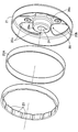
- FIG. 3 is an exploded perspective view of the rotor.
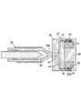
- FIG. 4 is a longitudinal sectional view showing a resin-bonded permanent magnet injection molding apparatus.
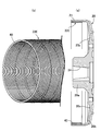
- First embodiment 5A and 5B show a second embodiment, in which FIG. 5A is a longitudinal sectional view of a rotor, and FIG. 5B is a perspective view of a yoke.
- (Second Embodiment) 6A and 6B show a third embodiment, in which FIG. 6A is a longitudinal sectional view of a rotor, and FIG.
- FIG. 6B is a perspective view of a yoke.
- FIG. 7A and 7B show a fourth embodiment, in which FIG. 7A is a longitudinal sectional view of a rotor, and FIG. 7B is a perspective view of a yoke.
- FIG. 8A and 8B show a fifth embodiment, in which FIG. 8A is a longitudinal sectional view of a rotor, and FIG. 8B is a perspective view of a yoke.
- FIG. 8A is a longitudinal sectional view of a rotor
- FIG. 8B is a perspective view of a yoke.
- the outer rotor type multipolar generator is used as an engine generator, for example.
- 11 is provided with a stator 12 fixed to a hollow support portion 11 a provided on the rotor 11 and a rotor 13 covering the stator 12. Is fixed.
- the stator 12 includes a ring-shaped stator core 15 formed by laminating and joining a plurality of magnetic steel plates, a synthetic resin bobbin 16 attached to the stator core 15, and the bobbin. 16 and a coil 17 wound around 16.
- Substantially T-shaped salient poles 15a are provided at a plurality of locations spaced at equal intervals in the circumferential direction of the outer circumference of the stator core 15, and the bobbin 16 is connected to the tip of the salient pole 15a and the stator core 15.
- the stator core 15 is formed so as to expose a part of both end surfaces and the inner peripheral surface, and the coil 17 is wound around the bobbin 16 at a portion corresponding to the salient pole 15a.
- Insertion holes 18 are provided in the inner peripheral portion of the stator core 15 at a plurality of locations spaced in the circumferential direction of the stator core 15, and bolts 19 inserted through the insertion holes 18 are provided in the support portion 11a.
- the stator 12 is fixed to the support portion 11a by screwing and tightening.
- the rotor 13 includes a hub 20 connected to the crankshaft 14, a cylindrical portion 21 having one end integrally connected to the hub 20, and an inner peripheral surface of the cylindrical portion 21.
- the hub 20 and the cylindrical portion 21 are integrally formed of a nonmagnetic material such as resin.
- the yoke 22A is formed in a cylindrical shape from a magnetic material.
- the yoke 22A which is an iron pipe, is fixed to the inner peripheral surface of the cylindrical portion 21 by press fitting.
- the hub 20 has a cylindrical support tube portion 20a into which the end portion of the crankshaft 14 is inserted and fixed, a ring portion 20b coaxially surrounding the support tube portion 20a, and a radial shape from the support tube portion 20a.
- a plurality of, for example, four connecting portions 20c that extend and are continuously connected to the ring portion 20b are integrally formed, and the cylindrical portion 21 is coaxially and integrally connected to the ring portion 20b. .
- the support cylinder 20a has a coaxial mounting hole 24 having a small diameter end at the end opposite to the engine body 11, and the end of the crankshaft 14 has the mounting hole at the end.
- a taper portion 14a to be fitted to 24 is formed.
- the support cylinder part 20a that is, the hub 20 is relatively located with respect to the crankshaft 14.
- a key 25 for preventing rotation is inserted, and a bolt 26 having an enlarged head portion 26a that comes into contact with and engages with the end surface of the support cylinder portion 20a opposite to the engine body 11 is connected to the crank. Screwed into the end of the shaft 14.
- the plurality of permanent magnets 23 are resin-bonded permanent magnets that are connected in series and integrated, and are polarized to the N pole and the S pole on the outer peripheral side and the inner peripheral side, and the polarity of the polarized poles is
- the poles adjacent to each other in the circumferential direction of the yoke 22A are mold-bonded to the inner peripheral surface of the yoke 22A so that the poles are different from the outer peripheral side and the inner peripheral side. Fixed and by a magnetic attractive force between the resin bonded magnet and the yoke).
- the mold device 27 includes the first mold 29, the second mold 30 that sandwiches the yoke 22A between the first mold 29, and the radially inner side of the yoke 22A.
- a ring-shaped magnetizing magnet 31 mounted on the first mold 29, and the cavity 32 is formed by the cooperation of the first mold 29, the second mold 30, the yoke 22A and the magnetizing magnet 31. It is formed.
- a sprue 33 connected to the nozzle 28 a at the tip of the injection machine 28, a plurality of gates 34 communicating with the cavity 32, and a runner 35 connecting the gates 34 and the sprue 33 are formed. Is done.
- a powder material 36 in which magnetic powder is covered with a resin to be coated is heated and melted and injected from the injection machine 28.
- the sprue 33, the runner 35 and the nozzles 28a of the injection machine 28 are used. It is injected into the cavity 32 through the gate 34.
- the material 36 heated and melted is magnetized by the magnetizing magnet 31 simultaneously with the molding in the cavity 32, and the permanent magnet 23, which is a resin-bonded permanent magnet integrated in a ring shape, is formed on the inner periphery of the yoke 22A. Mold bonded to the surface.
- the yoke 22A in which the permanent magnet 23 is molded and bonded to the inner peripheral surface in this way, is fixed to the inner peripheral surface of the cylindrical portion 21 by being press-fitted into the cylindrical portion 21 integrally connected to the hub 20.
- a hub 20 connected to the crankshaft 14 and a cylindrical portion 21 having one end connected to the hub 20 are integrally formed of a resin which is a nonmagnetic material. Since the yoke 22A is fixed to the inner peripheral surface of the cylindrical portion 21, it becomes easy to match the central axis of the hub 20 with the central axis of the inner peripheral surface of the cylindrical portion 21, and the yoke 22A is centered. Can be easy. Furthermore, the centering accuracy of the yoke 22A can be further improved by subjecting the taper-shaped mounting hole 24 of the support cylinder portion 20a of the hub 20 to additional cutting with reference to the central axis of the hub 20. . In addition, the thickness of the yoke 22A can be reduced, and the weight of the rotor 13 can be reduced due to the fact that the hub 20 and the cylindrical portion 21 are made of resin.
- the permanent magnet 23 fixed to the inner peripheral surface of the yoke 22A is a resin-bonded permanent magnet molded and bonded to the inner peripheral surface of the yoke 22A by injection molding, it has the same magnetomotive force as compared with the conventional ferrite magnet. It is possible to reduce the volume to be obtained, and it is possible to reduce the weight and facilitate the assembly of the permanent magnet 23.
- the resin-bonded permanent magnet formed by injection molding is molded on the inner peripheral surface of the yoke 22A before being fixed to the cylindrical portion 21, but the cylindrical portion integrated with the hub 20 is used. It is also possible to mold-bond a resin-bonded permanent magnet that is injection-molded to the inner peripheral surface of the yoke 22 ⁇ / b> A press-fitted into 21. Thereby, it becomes easy to match the center axis of the hub 20 with the center axis of the inner peripheral surface of the resin bonded magnet that is injection-molded on the inner peripheral surface of the yoke 22A, and centering can be facilitated.
- the hub 20 and the cylindrical portion 21 are integrally formed of resin.
- the hub 20 and the cylindrical portion 21 are made of a light alloy such as aluminum, magnesium, or titanium.
- the same effect can be achieved.
- the yoke 22B is formed by winding a magnetic metal strip 37 a plurality of times or only once (twice in this embodiment). May be configured.
- the yoke 22C may be configured such that a belt plate 38 made of magnetic metal is spirally wound.
- the yoke 22C may be formed by cutting the cylinder 38 into a necessary length as shown by a chain line in FIG.
- the yoke 22D is configured such that a wire rod 39 made of a magnetic metal and having a rectangular cross section is spirally wound.
- the yoke 22D may be formed by cutting the wire 39 into a required length as shown by a chain line in FIG.
- the yoke 22E is configured such that a wire 40 made of a magnetic metal and having a circular cross-sectional shape is spirally wound.
- the yoke 22E may be formed by cutting the wire 40 into a necessary length as shown by a chain line in FIG.
- the yoke 22E is fixed to the inner peripheral surface of the cylindrical portion 21 by being screwed into the cylindrical portion 21, but a female screw may be formed in advance on the inner peripheral surface of the cylindrical portion 21 for the screwing. Then, the center axis of the yoke 22E can be matched with the center axis of the hub 20 with high accuracy by increasing the accuracy of the female screw.
- the screwing direction of the yoke 22E into the cylindrical portion 21 is preferably set in the direction opposite to the rotation direction of the hub 20 and the cylindrical portion 21, that is, the direction of rotation of the crankshaft 14.
- the yoke 22E is screwed by the cylindrical portion 21 according to the rotation, and the yoke 22E is securely fixed to the inner peripheral surface of the cylindrical portion 21.
- a plurality of permanent magnets are composed of a plurality of single magnets that are composed of ferrite, rare earth, or bonded magnets and have N-pole and S-pole magnetic poles, and these single-piece magnets are arranged on the inner peripheral surface of the yoke in the circumferential direction.
- the adjacent single magnets may be arranged so that the polarities of the adjacent single magnets are different on the inner and outer peripheral sides.
Landscapes
- Engineering & Computer Science (AREA)
- Power Engineering (AREA)
- Iron Core Of Rotating Electric Machines (AREA)
- Permanent Magnet Type Synchronous Machine (AREA)
- Permanent Field Magnets Of Synchronous Machinery (AREA)
Abstract
L'invention porte sur un générateur multipolaire du type à rotor externe, qui est équipé d'un stator fixe et d'un rotor qui entoure coaxialement le stator et qui est formé sous une forme cylindrique, et est pourvu de multiples aimants permanents sur la surface circonférentielle intérieure d'une culasse accouplée à un arbre d'entraînement et formée à partir d'un matériau magnétique. Un moyeu (20) accouplé à l'arbre d'entraînement (14) et une partie cylindrique (21) dont une extrémité est continue avec le moyeu (20) sont formés d'un seul tenant à partir d'un matériau non magnétique, et la culasse (22A) est fixée à la surface circonférentielle intérieure de la partie cylindrique (21). Il est ainsi possible d'obtenir une structure de rotor plus légère pour laquelle le centrage de la culasse est plus facile.
Applications Claiming Priority (2)
| Application Number | Priority Date | Filing Date | Title |
|---|---|---|---|
| JP2016-083979 | 2016-04-19 | ||
| JP2016083979A JP2017195690A (ja) | 2016-04-19 | 2016-04-19 | アウターロータ型多極発電機におけるロータ構造 |
Publications (1)
| Publication Number | Publication Date |
|---|---|
| WO2017183378A1 true WO2017183378A1 (fr) | 2017-10-26 |
Family
ID=60115801
Family Applications (1)
| Application Number | Title | Priority Date | Filing Date |
|---|---|---|---|
| PCT/JP2017/011430 Ceased WO2017183378A1 (fr) | 2016-04-19 | 2017-03-22 | Structure de rotor pour générateur multipolaire du type à rotor externe |
Country Status (2)
| Country | Link |
|---|---|
| JP (1) | JP2017195690A (fr) |
| WO (1) | WO2017183378A1 (fr) |
Cited By (3)
| Publication number | Priority date | Publication date | Assignee | Title |
|---|---|---|---|---|
| WO2020090447A1 (fr) * | 2018-10-30 | 2020-05-07 | 株式会社デンソー | Machine rotative électrique |
| US20220006339A1 (en) * | 2019-03-19 | 2022-01-06 | Denso Corporation | Rotating electrical machine and method of manufacturing rotor |
| WO2022065306A1 (fr) | 2020-09-25 | 2022-03-31 | ダイキン工業株式会社 | Moteur, soufflante et climatiseur |
Families Citing this family (3)
| Publication number | Priority date | Publication date | Assignee | Title |
|---|---|---|---|---|
| JP7225901B2 (ja) | 2019-02-25 | 2023-02-21 | 株式会社デンソー | 回転電機 |
| JP7379011B2 (ja) | 2019-08-09 | 2023-11-14 | ミネベアミツミ株式会社 | 回転機器 |
| DE102022210700A1 (de) | 2022-10-11 | 2024-04-11 | Robert Bosch Gesellschaft mit beschränkter Haftung | Elektronisch kommutierter Elektromotor in Außenläuferbauart und Verfahren zu dessen Herstellung |
Citations (2)
| Publication number | Priority date | Publication date | Assignee | Title |
|---|---|---|---|---|
| JP2005287107A (ja) * | 2004-03-26 | 2005-10-13 | Aisin Seiki Co Ltd | 回転電機のロータ |
| JP2005341791A (ja) * | 2004-05-22 | 2005-12-08 | Minebea Co Ltd | モータ、特にスピンドルモータ |
-
2016
- 2016-04-19 JP JP2016083979A patent/JP2017195690A/ja active Pending
-
2017
- 2017-03-22 WO PCT/JP2017/011430 patent/WO2017183378A1/fr not_active Ceased
Patent Citations (2)
| Publication number | Priority date | Publication date | Assignee | Title |
|---|---|---|---|---|
| JP2005287107A (ja) * | 2004-03-26 | 2005-10-13 | Aisin Seiki Co Ltd | 回転電機のロータ |
| JP2005341791A (ja) * | 2004-05-22 | 2005-12-08 | Minebea Co Ltd | モータ、特にスピンドルモータ |
Cited By (5)
| Publication number | Priority date | Publication date | Assignee | Title |
|---|---|---|---|---|
| WO2020090447A1 (fr) * | 2018-10-30 | 2020-05-07 | 株式会社デンソー | Machine rotative électrique |
| US20220006339A1 (en) * | 2019-03-19 | 2022-01-06 | Denso Corporation | Rotating electrical machine and method of manufacturing rotor |
| US12155269B2 (en) * | 2019-03-19 | 2024-11-26 | Denso Corporation | Rotating electrical machine and method of manufacturing rotor |
| WO2022065306A1 (fr) | 2020-09-25 | 2022-03-31 | ダイキン工業株式会社 | Moteur, soufflante et climatiseur |
| US12051945B2 (en) | 2020-09-25 | 2024-07-30 | Daikin Industries, Ltd. | Motor, fan, and air conditioner |
Also Published As
| Publication number | Publication date |
|---|---|
| JP2017195690A (ja) | 2017-10-26 |
Similar Documents
| Publication | Publication Date | Title |
|---|---|---|
| WO2017183378A1 (fr) | Structure de rotor pour générateur multipolaire du type à rotor externe | |
| CN103580326B (zh) | 转子以及马达 | |
| US8729760B2 (en) | Rotor of electric motor having structure for attaching magnet securely to outer circumferential surface of rotor core and manufacturing method thereof | |
| CN111293848B (zh) | 无槽无刷直流马达/致动器 | |
| US20130069469A1 (en) | Rotor of motor, method of producing the rotor, inner rotor-type brushless motor and method of producing the motor | |
| US10848037B2 (en) | Permanent magnet rotor, method for the production thereof using a magnetizing fixture | |
| JP5501660B2 (ja) | 電動モータ及びそのロータ | |
| KR102082573B1 (ko) | 요크 권선을 가진 능동 방사형 자기 베어링 | |
| US20200153322A1 (en) | Rotor structure in outer rotor type electric motor | |
| DE102014115563A1 (de) | Rotor und Motor | |
| US20060202580A1 (en) | Motor | |
| US10418870B2 (en) | Synchronous reluctance motor with magnetic leakage path saturated by permanent magnets | |
| WO2020059654A1 (fr) | Rotor pour moteur électrique de type à rotor externe | |
| MY136315A (en) | Motor | |
| CN106253518A (zh) | 转子、马达以及转子的制造方法 | |
| JP2012010571A (ja) | 回転電機用磁石ロータ及びその製造方法並びにインナーロータ型モータ | |
| JPH11243654A (ja) | 回転電機用磁石回転子 | |
| CN104756367A (zh) | 用于电动机的转子 | |
| US9787153B2 (en) | Outer rotor type dynamo | |
| JP2006136068A (ja) | 永久磁石形同期モータ | |
| KR100972444B1 (ko) | 브러시리스 모터의 회전자 | |
| JP2018023218A (ja) | アウターロータ型多極発電機におけるロータ構造 | |
| JP2008099445A (ja) | 回転電機のインナロータ | |
| JP3187632U (ja) | ハイブリッド型ステッピングモータ用ロータ | |
| JP5282577B2 (ja) | モータ |
Legal Events
| Date | Code | Title | Description |
|---|---|---|---|
| DPE1 | Request for preliminary examination filed after expiration of 19th month from priority date (pct application filed from 20040101) | ||
| NENP | Non-entry into the national phase |
Ref country code: DE |
|
| 121 | Ep: the epo has been informed by wipo that ep was designated in this application |
Ref document number: 17785720 Country of ref document: EP Kind code of ref document: A1 |
|
| 122 | Ep: pct application non-entry in european phase |
Ref document number: 17785720 Country of ref document: EP Kind code of ref document: A1 |