WO2017183533A1 - Programme de traitement d'images et dispositif de traitement d'images - Google Patents
Programme de traitement d'images et dispositif de traitement d'images Download PDFInfo
- Publication number
- WO2017183533A1 WO2017183533A1 PCT/JP2017/014944 JP2017014944W WO2017183533A1 WO 2017183533 A1 WO2017183533 A1 WO 2017183533A1 JP 2017014944 W JP2017014944 W JP 2017014944W WO 2017183533 A1 WO2017183533 A1 WO 2017183533A1
- Authority
- WO
- WIPO (PCT)
- Prior art keywords
- medicine
- drug
- display device
- image
- discrimination
- Prior art date
- Legal status (The legal status is an assumption and is not a legal conclusion. Google has not performed a legal analysis and makes no representation as to the accuracy of the status listed.)
- Ceased
Links
Images















Classifications
-
- G—PHYSICS
- G06—COMPUTING OR CALCULATING; COUNTING
- G06T—IMAGE DATA PROCESSING OR GENERATION, IN GENERAL
- G06T7/00—Image analysis
- G06T7/0002—Inspection of images, e.g. flaw detection
- G06T7/0004—Industrial image inspection
- G06T7/001—Industrial image inspection using an image reference approach
-
- A—HUMAN NECESSITIES
- A61—MEDICAL OR VETERINARY SCIENCE; HYGIENE
- A61J—CONTAINERS SPECIALLY ADAPTED FOR MEDICAL OR PHARMACEUTICAL PURPOSES; DEVICES OR METHODS SPECIALLY ADAPTED FOR BRINGING PHARMACEUTICAL PRODUCTS INTO PARTICULAR PHYSICAL OR ADMINISTERING FORMS; DEVICES FOR ADMINISTERING FOOD OR MEDICINES ORALLY; BABY COMFORTERS; DEVICES FOR RECEIVING SPITTLE
- A61J3/00—Devices or methods specially adapted for bringing pharmaceutical products into particular physical or administering forms
-
- G—PHYSICS
- G06—COMPUTING OR CALCULATING; COUNTING
- G06K—GRAPHICAL DATA READING; PRESENTATION OF DATA; RECORD CARRIERS; HANDLING RECORD CARRIERS
- G06K19/00—Record carriers for use with machines and with at least a part designed to carry digital markings
- G06K19/06—Record carriers for use with machines and with at least a part designed to carry digital markings characterised by the kind of the digital marking, e.g. shape, nature, code
-
- G—PHYSICS
- G06—COMPUTING OR CALCULATING; COUNTING
- G06T—IMAGE DATA PROCESSING OR GENERATION, IN GENERAL
- G06T7/00—Image analysis
-
- G—PHYSICS
- G06—COMPUTING OR CALCULATING; COUNTING
- G06V—IMAGE OR VIDEO RECOGNITION OR UNDERSTANDING
- G06V20/00—Scenes; Scene-specific elements
- G06V20/60—Type of objects
- G06V20/66—Trinkets, e.g. shirt buttons or jewellery items
-
- G—PHYSICS
- G16—INFORMATION AND COMMUNICATION TECHNOLOGY [ICT] SPECIALLY ADAPTED FOR SPECIFIC APPLICATION FIELDS
- G16H—HEALTHCARE INFORMATICS, i.e. INFORMATION AND COMMUNICATION TECHNOLOGY [ICT] SPECIALLY ADAPTED FOR THE HANDLING OR PROCESSING OF MEDICAL OR HEALTHCARE DATA
- G16H20/00—ICT specially adapted for therapies or health-improving plans, e.g. for handling prescriptions, for steering therapy or for monitoring patient compliance
- G16H20/10—ICT specially adapted for therapies or health-improving plans, e.g. for handling prescriptions, for steering therapy or for monitoring patient compliance relating to drugs or medications, e.g. for ensuring correct administration to patients
-
- G—PHYSICS
- G16—INFORMATION AND COMMUNICATION TECHNOLOGY [ICT] SPECIALLY ADAPTED FOR SPECIFIC APPLICATION FIELDS
- G16H—HEALTHCARE INFORMATICS, i.e. INFORMATION AND COMMUNICATION TECHNOLOGY [ICT] SPECIALLY ADAPTED FOR THE HANDLING OR PROCESSING OF MEDICAL OR HEALTHCARE DATA
- G16H30/00—ICT specially adapted for the handling or processing of medical images
- G16H30/40—ICT specially adapted for the handling or processing of medical images for processing medical images, e.g. editing
-
- G—PHYSICS
- G16—INFORMATION AND COMMUNICATION TECHNOLOGY [ICT] SPECIALLY ADAPTED FOR SPECIFIC APPLICATION FIELDS
- G16H—HEALTHCARE INFORMATICS, i.e. INFORMATION AND COMMUNICATION TECHNOLOGY [ICT] SPECIALLY ADAPTED FOR THE HANDLING OR PROCESSING OF MEDICAL OR HEALTHCARE DATA
- G16H70/00—ICT specially adapted for the handling or processing of medical references
- G16H70/40—ICT specially adapted for the handling or processing of medical references relating to drugs, e.g. their side effects or intended usage
-
- A—HUMAN NECESSITIES
- A61—MEDICAL OR VETERINARY SCIENCE; HYGIENE
- A61J—CONTAINERS SPECIALLY ADAPTED FOR MEDICAL OR PHARMACEUTICAL PURPOSES; DEVICES OR METHODS SPECIALLY ADAPTED FOR BRINGING PHARMACEUTICAL PRODUCTS INTO PARTICULAR PHYSICAL OR ADMINISTERING FORMS; DEVICES FOR ADMINISTERING FOOD OR MEDICINES ORALLY; BABY COMFORTERS; DEVICES FOR RECEIVING SPITTLE
- A61J2205/00—General identification or selection means
- A61J2205/40—General identification or selection means by shape or form, e.g. by using shape recognition
Definitions
- the present invention relates to an image processing program and an image processing apparatus.
- Patent Document 1 a drug identification device that automatically identifies a drug
- the medicine discrimination device various images for distinguishing the medicine are displayed on the display device for an operator who performs the discrimination, but an image that can improve the accuracy of the discrimination is displayed on the display device. This is very important.
- An object of one embodiment of the present invention is to contribute to improvement in accuracy of drug discrimination.
- the program according to an embodiment of the present invention includes a step of displaying an image obtained by imaging an area including a plurality of medicines on a display device, an image of a representative medicine selected from the plurality of medicines displayed on the display device, and the And causing the computer to execute a step of rearranging the images of the plurality of medicines and displaying them on the display device based on the similarity to the images of the plurality of medicines.
- An image processing apparatus includes a receiving unit that receives an image obtained by photographing a region including a plurality of medicines by a medicine photographing device, and an image obtained by photographing the region received by the receiving unit on a display device. Sorting the plurality of medicine images based on the step of displaying and the similarity between the representative medicine image selected from the plurality of medicines displayed on the display device and each of the plurality of medicine images. And an image processing unit that executes the step of displaying on the display device.
- FIG. 1 is a schematic diagram showing an outline of a drug discrimination system.
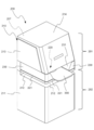
- FIG. 2 is a perspective view of the embodiment of the medicine imaging apparatus.
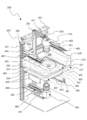
- FIG. 3 is a perspective view showing a state in which the front cover of the medicine photographing apparatus shown in FIG. 2 is opened.
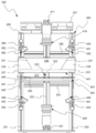
- FIG. 4 is a perspective view showing an internal configuration of the medicine photographing apparatus shown in FIG.
- FIG. 5 is a front view of the medicine photographing apparatus shown in FIG.
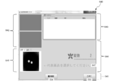
- FIG. 6 is an image at the initial stage after the drug identification software is activated.
- FIG. 7 is an image of the first stage of the returned tablet image discrimination.
- FIG. 8 is an image image of the second stage of the drug image discrimination started in FIG.
- FIG. 9 is an image of a third stage of drug image discrimination that started in FIG. FIG.
- FIG. 10 is an image image of the fourth stage of drug image discrimination started in FIG.
- FIG. 11 is an image image of the fifth stage of the drug image discrimination started in FIG.
- FIG. 12 is a diagram for explaining rearrangement of images of a plurality of medicines, and is a diagram illustrating a state of a first portion where a plurality of medicines are placed.
- FIG. 13 is a diagram showing display on a third part of a plurality of drugs by a general drug discrimination program.
- FIG. 14 is a diagram showing display on a third part of a plurality of medicines by the medicine discrimination program of the present embodiment.
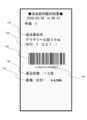
- FIG. 15 is a diagram illustrating an example of a printed returned-goods medicine discrimination result.
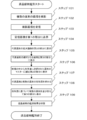
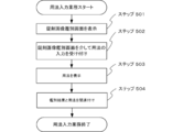
- FIG. 16 is a flowchart of processing executed by the image processing program.
- FIG. 16 is a flowchart of processing executed by the image processing program.
- FIG. 17 is a schematic diagram showing an outline of the medicine packaging system of the present embodiment.
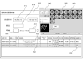
- FIG. 18 is a diagram illustrating an example of an inquiry screen for a filling history of a medicine filled in the packaging device.
- FIG. 19 is a diagram illustrating an example of an inquiry screen for a filling history of a medicine filled in the packaging device.
- FIG. 20 is a diagram illustrating an example of a printed returned-goods medicine discrimination result.
- FIG. 21 is a diagram showing an example of an environment setting screen for setting whether or not to print the number of identified medicines and the total drug price.
- FIG. 22 is an example of an image image in discrimination of a brought-in drug.
- FIG. 23 is a flowchart of a task of counting work time and cost required for drug discrimination.
- FIG. 23 is a flowchart of a task of counting work time and cost required for drug discrimination.
- FIG. 24 is a diagram illustrating an example of a screen for performing aggregation related to drug discrimination.
- FIG. 25 is a diagram illustrating an example of a screen for performing aggregation related to drug discrimination.
- FIG. 26 is a diagram illustrating an example of a totaling result screen such as identification time required for identifying a medicine.
- FIG. 27 is a diagram illustrating an example of a totaling result screen such as identification time required for identifying a drug.
- FIG. 28 is a flowchart of the sending item display job.
- FIG. 29 is a diagram illustrating an example of a state in which a notification item related to drug discrimination is displayed.
- FIG. 30 is a diagram illustrating an example of a state in which a notification item regarding drug discrimination is displayed.
- FIG. 31 is a diagram illustrating an example of a state in which presence / absence of a notification item related to drug discrimination is displayed.
- FIG. 32 is a diagram illustrating an example of a screen for editing a notification item related to drug discrimination.
- FIG. 33 is a flowchart of a patient information input task.
- FIG. 34 is a diagram illustrating an example of a state in which information related to a patient of a brought-in drug is displayed on a screen for performing drug discrimination.
- FIG. 35 is a diagram illustrating an example of a screen for inputting attributes of a patient who brought a medicine.
- FIG. 36 is a diagram illustrating an example of a screen for inputting attributes of a patient who brought a medicine.
- FIG. 37 is a flowchart of usage input work.
- FIG. 37 is a flowchart of usage input work.
- FIG. 38 is a diagram showing an example of a discrimination screen for discriminating drugs brought by patients.
- FIG. 39 is a diagram showing an example of a screen for inputting the usage of the medicine brought by the patient via the discrimination screen for identifying the medicine brought by the patient.
- FIG. 40 is a diagram illustrating an example of a screen for inputting the usage of the medicine brought by the patient via the discrimination screen for differentiating the medicine brought by the patient.
- FIG. 41 is a flowchart of the RP switching task.
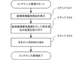
- FIG. 42 is a flowchart of maintenance work.
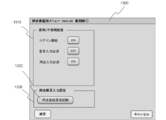
- FIG. 43 is a diagram illustrating an example of a screen for changing settings relating to drug discrimination.
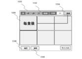
- FIG. 44 is a diagram illustrating an example of a screen for registering drug usage.
- FIG. 45 is a flowchart of the manual search operation for a differential medicine.
- FIG. 46 is a diagram illustrating an example of a screen for manually searching for drugs through a discrimination screen for identifying drugs.
- FIG. 47 is a diagram illustrating an example of a screen for manually searching for medicines.
- FIG. 48 is a diagram illustrating an example of a screen for manually searching for medicines.
- FIG. 49 is a diagram illustrating an example of a state in which a manually searched medicine is displayed on the discrimination screen as a discrimination result.
- FIG. 50 is a flowchart of the serial number printing job.
- FIG. 51 is a diagram showing an example of a printed medicine discrimination result.
- FIG. 52 is a diagram showing an example of a printed medicine discrimination result.
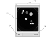
- FIG. 53 is a diagram for explaining the drug region editing function.
- FIG. 54 is a diagram showing an example of the area editing screen.
- FIG. 55 is a diagram showing an example of the cut area editing screen.
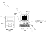
- FIG. 1 is a schematic diagram showing an outline of a drug discrimination system.
- the drug discrimination system 100 includes a drug imaging device 200 and a computer 500.
- the medicine imaging apparatus 200 images the medicine
- the computer 500 discriminates the medicine based on the obtained image data of the medicine.
- the computer 500 includes a receiving unit 510 that receives an image captured by the medicine imaging device 200, a main body 520 that includes a CPU (image processing unit), a storage device, a recording device, and the like, and a display device 530 that functions as an output device.
- a keyboard 541 and a mouse 542 functioning as an input device are provided.
- the display device 530 includes a screen 531 and a touch screen 532, and the user can input to the computer 500 via the touch screen 532.
- an image processing program 600 is installed in the computer 500. From this point of view, the computer 500 in which an image processing program (also referred to as image processing software) 600 is installed can also be called an image processing apparatus.
- the image processing program 600 is also referred to as a drug discrimination program because the computer 500 performs various processes related to drug discrimination as an example.
- the medicine discrimination program since the medicine discrimination program is installed in the computer 500, the computer 500 can also be called a medicine discrimination apparatus.
- the computer 500 is configured by a so-called PC (personal computer), and the image processing program 600 is stored in a recording device in the PC.
- the computer 500 is not a PC, for example, It may be a microcomputer incorporated in another device.
- the image processing program 600 may be written in a storage device such as a ROM (read only memory) of the device.
- the CPU of the main body 520 can also be referred to as an image processing unit that executes various types of image processing according to the image processing program 600.
- a user When performing drug discrimination, first, a user (for example, a pharmacist or the like) sets a drug to be identified in the drug imaging apparatus 200. Next, when the user operates the computer 500, the medicine imaging apparatus 200 performs imaging of the medicine. The taken image of the medicine is transmitted to the computer 500 as data. Then, the computer 500 searches for a medicine with reference to a database (not shown) based on the image data.
- a database not shown
- the computer 500 has a built-in database.
- the computer 500 refers to the MD bank without accessing the external database. Can be searched.
- the computer 500 accesses a database via a network.
- the drug instruction support system “Pharma Road” (trademark) manufactured by Yuyama Manufacturing Co., Ltd. is installed on another computer (server) in the same facility, the computer 500 is connected to a local area network (LAN). You can search for drugs by accessing Pharma Road in the server.
- the computer 500 may access the database via the Internet.
- FIG. 2 is a perspective view showing an appearance of the medicine photographing apparatus 200.
- the upper side from the placement unit 220 is referred to as an upper part 201 and the lower side is referred to as a lower part 202.
- the lower case 211 covers the lower part 202 of the medicine photographing apparatus 200.
- a cutout 212 extending in the horizontal direction is formed on the upper surface of the lower case 211.
- the notch 212 is open in the left-right direction and the front direction of the medicine photographing apparatus 200. Through this notch 212, the user can insert a long wrapping paper into the medicine photographing apparatus 200. Specifically, the wrapping paper is spread in the horizontal direction and inserted into the notch 212 from the front side. Then, the wrapping paper is moved near the center of the medicine photographing apparatus 200. Thereby, the internal camera of the medicine photographing apparatus 200 can photograph the medicine enclosed in the inside of the wrapping paper without cutting the wrapping paper.
- the internal space of the medicine photographing apparatus 200 communicates with the external space in the left-right direction by the notch portion 212, even when the wrapping paper is longer than the width of the medicine photographing apparatus 200, the user can remove the wrapping paper.
- the wrapping paper can be easily inserted into the medicine photographing apparatus 200 in the unwound state.
- a tray support member 221 that supports a member that stores a medicine is provided immediately above the notch 212. Specifically, the tray 300 is placed on the tray support member 221.
- the upper surface of the medicine imaging apparatus 200 and the upper part 201 on the front surface are covered with a cover 214.
- the cover 214 can be opened upward.
- the cover 214 is hinged by a hinge 257 (see FIG. 4) at the upper end of the back surface of the upper case 213, and the cover 214 can be rotated in the vertical direction around the hinge 257.
- FIG. 3 shows a state where the cover 214 of the medicine photographing apparatus 200 is opened.
- an upper internal space 240 that is an upper portion 201 of the internal space of the medicine photographing apparatus 200 is opened to a space in front of the medicine photographing apparatus 200.
- the user can set the tray 300 to the fitting portion 223 of the placement portion 220 through the upper inner space 240.
- the front side outer surface of the upper case 213 has a substantially inverted U shape.
- This front side outer surface is inclined, and an inclined portion 215 is formed thereby.
- the inclined portion 215 is inclined so that the distance from the back surface of the medicine photographing apparatus 200 becomes smaller from the bottom to the top.
- the tray 300 is less likely to collide with the upper case 213.
- the front surface of the cover 214 is configured to cover the inclined portion 215. Therefore, when the cover 214 is closed, the front surface thereof is located in the vicinity of the inclined portion 215 and is parallel to the inclined portion 215.
- the upper surface and the front surface of the cover 214 are obtuse, corresponding to the obtuse angle between the upper surface of the upper case 213 and the inclined portion 215.
- the lower end of the inclined portion 215 is located on the back side of the guide member 230 and the outer front surface of the lower case 211. That is, the distance from the back surface of the medicine imaging apparatus 200 to the lower end of the inclined portion 215 is smaller than the distance from the back surface of the medicine imaging apparatus 200 to the outer front surface of the guide member 230 and the outer front surface of the lower case 211. With this configuration, the user can more easily put the tray 300 into the upper internal space 240.
- an inclined surface 216 different from the inclined portion 215 is provided on the outer surface on the front side of the upper case 213. More specifically, the slope 216 is provided inside the U shape of the substantially inverted U-shaped inclined portion 215. The slope 216 is provided on the front surface of a first camera 410 (see FIG. 4), which will be described later, and protects the first camera 410. Thereby, when the user inserts the tray 300 into the upper internal space 240, it is possible to prevent the position and orientation of the first camera 410 from being shifted due to the tray 300 hitting the first camera 410. As shown in FIG. 3, the inclined surface 216 has a substantially rectangular shape and extends in the left-right direction of the medicine photographing apparatus 200.
- the distance from the back surface of the medicine photographing apparatus 200 to the inclined surface 216 gradually decreases from the top to the bottom. That is, the horizontal position of the upper end of the slope 216 is closer to the back surface of the medicine photographing apparatus 200 than the horizontal position of the lower end of the slope 216. This makes it difficult for the tray 300 to collide with the slope 216 during insertion, and the user can easily put the tray 300 in the back of the upper internal space 240.
- a pair of guide members 230 are provided between the upper case 213 and the placement portion 220.
- the outer side surface of the guide member 230 extends in the vertical direction and is located on the same plane as the outer side surface of the upper case 213.
- the inner side surface of the guide member 230 is inclined with respect to the vertical direction, whereby an inclined surface 231 is formed.
- the inclined surface 231 has a substantially square shape and extends in the front-rear direction of the medicine photographing apparatus 200.
- the slope 231 faces the upper internal space 240.
- One of the inclined surfaces 231 is located on the upper right side of the placement unit 220, and the other is located on the upper left side of the placement unit 220.
- the slope 231 is formed so as to approach the central axis of the medicine imaging apparatus 200 as it goes from top to bottom. That is, when viewed in plan, the horizontal position of the lower end of the inclined surface 231 is closer to the placement unit 220 than the horizontal position of the upper end. Furthermore, the distance between the lower ends of the two inclined surfaces 231 is substantially the same as or slightly larger than the width of the fitting portion 223 of the tray support member 221. Specifically, the distance between the lower ends of the two inclined surfaces 231 is preferably about 1 to 1.2 times the width of the fitting portion 223.
- FIG. 4 is a perspective view of the medicine photographing apparatus 200
- FIG. 5 is a front view.
- a frame 250 is provided on the back side of the medicine photographing apparatus 200. Many of the main members of the medicine photographing apparatus 200 are directly or indirectly attached to the frame 250.
- the frame 250 includes a first column 251, a second column 252, a third column 253, a first beam 254, a second beam 255, a third beam 256, and a hinge 257.
- the first column 251 is provided on the left side of the back of the medicine photographing apparatus 200
- the second column 252 is provided in the center of the back
- the third column 253 is provided on the right side of the back.
- the first column 251, the second column 252, and the third column 253 are connected by the first beam 254, the second beam 255, and the third beam 256.
- a hinge 257 for rotating the cover 214 is attached to the third beam 256 positioned at the top of the frame 250.
- the medicine photographing apparatus 200 includes a first camera 410, a second camera 420, a first light source 430, a second light source 440, a third light source 450, a fourth light source 460, and a tray support member 221. , And a guide member 230.
- the tray support member 221 and the guide member 230 are directly attached to the frame 250.
- the first camera 410, the second camera 420, the third light source 450, and the fourth light source 460 are provided via the support member. Attached to the frame 250.
- the first light source 430 is accommodated in the tray support member 221 and supported by the tray support member 221.
- the second light source 440 is attached to the lower case 211 (see FIG. 2) via a support member.
- the main members inside the medicine photographing apparatus 200 are attached to the frame 250 instead of the case 210. This facilitates removal of the case 210 and facilitates maintenance work of the internal main members.
- the tray support member 221 is provided in the vicinity of the central portion of the medicine photographing apparatus 200.
- a guide member 230 is provided immediately above the tray support member 221.
- a third light source 450 is provided above the guide member 230.
- a first camera 410 is provided at a position higher than the third light source 450, that is, in the vicinity of the upper surface of the medicine photographing apparatus 200.
- a second light source 440 is provided below the tray support member 221 at a predetermined distance.
- a fourth light source 460 is provided near the side surface of the medicine photographing apparatus 200 at a position lower than the second light source 440.
- a second camera 420 is provided at a position lower than the fourth light source 460, that is, near the bottom surface of the medicine photographing apparatus 200.
- the first light source 430 and the third light source 450 constitute an upper light source.
- the second light source 440 and the fourth light source 460 constitute a lower light source.
- the tray support member 221 is provided in the vicinity of the central portion of the medicine photographing apparatus 200 and above the space 217 for the notch portion 212.
- a first light source 430 is attached to the bottom of the tray support member 221.
- the first light source 430 includes a first ring illumination 431.
- the first ring illumination 431 includes a plurality of light emitting diodes (LEDs) arranged in an annular shape. The plurality of LEDs are arranged so as to surround the outer periphery of the hole 222 of the tray support member 221 and face the hole 222.
- a third light source 450 is provided above the guide member 230.
- the third light source 450 includes a plurality of bar lights, specifically, a first bar light 451 and a second bar light 452.
- the first bar illumination 451 is attached to the third pillar 253 via the support member 453.
- the second bar illumination 452 is attached to the first pillar 251 via the support member 454.
- the first bar illumination 451 and the second bar illumination 452 are provided on the side of the medicine photographing apparatus 200, specifically on the side of the placement unit 220. As shown in FIG.
- the first bar illumination 451 and the second bar illumination 452 are installed in a direction parallel to the front-rear direction of the medicine photographing apparatus 200, and the first bar illumination 451 and the second bar illumination 452 emit light.
- the surface faces obliquely downward, more specifically, to the mounting portion 220.
- the distance from the first bar illumination 451 and the second bar illumination 452 to the place where the medicine on the placement unit 220 is placed is from the first ring illumination 431 to the place where the medicine on the placement part 220 is placed. Greater than the distance.
- first bar illumination 451 and the second bar illumination 452 are installed at a position closer to the side surface of the medicine photographing apparatus 200 than the lower end of the inclined surface 231 of the guide member 230 and the outer periphery of the hole 222 of the tray support member 221. Yes. With such an arrangement of the third light source 450, a large space is secured in the upper internal space 240, and the user can easily place the tray 300 on the placement unit 220.
- the first bar illumination 451 and the second bar illumination 452 include a polarizing filter, and the diffused light is configured to reach the medicine through the polarizing filter.
- the direct light from the first bar illumination 451 and the second bar illumination 452 is cut by the polarization filter, and the light diffused by the polarization filter is the hole 222 of the tray support member 221, that is, the ring of the first ring illumination 431. It is configured to reach the drug through the inside.
- the third light source 450 functions as a diffusion light source or an indirect light source. Thereby, the upper side of the medicine is suitably illuminated.
- the present inventor has found that when the third light source 450 is configured as described above, the print on the surface of the medicine can be clearly photographed. In addition, it is possible to photograph clearly whether the medicine is a tablet or a capsule.
- a fourth light source 460 of the same type as the third light source 450 is provided below the second light source 440.
- the fourth light source 460 includes a plurality of bar lights, specifically, a third bar lamp 461 and a fourth bar lamp 462.
- the third bar illumination 461 is attached to the third pillar 253 via the support member 463.
- the fourth bar illumination 462 is attached to the first column 251 via the support member 464.
- the third bar illumination 461 and the fourth bar illumination 462 are provided on the side of the medicine photographing apparatus 200, similarly to the first bar illumination 451 and the second bar illumination 452.
- the 3rd bar illumination 461 and the 4th bar illumination 462 are installed in the direction parallel to the front-back direction of the chemical
- the light emitting surfaces of the third bar illumination 461 and the fourth bar illumination 462 are obliquely upward, more specifically, facing the placement unit 220.
- the distance from the third bar illumination 461 and the fourth bar illumination 462 to the placement unit 220 is the distance from the second ring illumination 441 to the placement unit 220. Bigger than.
- the third bar illumination 461 and the fourth bar illumination 462 are each provided with a polarizing filter, and light diffused through the polarizing filter reaches the medicine. It is configured as follows. Specifically, the diffused light from the third bar illumination 461 and the fourth bar illumination 462 passes through the ring of the second ring illumination 441 and reaches the medicine. Thereby, the lower side of the medicine is illuminated so that the printing becomes clear.
- the third light source 450 and the fourth light source 460 are each configured with two bar lights, but in other embodiments, four bar lights may be provided. In this case, it is preferable to arrange the bar lights so that the four bar lights form a quadrangle and surround the placement unit 220.
- a first camera 410 is installed above the first bar illumination 451 and the second bar illumination 452.
- the first camera 410 is attached to the second pillar 252 via an attachment member 411.
- the first camera 410 is fixed by the attachment member 411 so as to be positioned vertically above the placement unit 220 and to face the placement unit 220.
- the photographing region of the first camera 410 includes the hole 222 of the tray support member 221 and the inside of the ring of the first ring illumination 431.
- the 1st camera 410 can image
- a second camera 420 is installed below the third bar illumination 461 and the fourth bar illumination 462.
- the second camera 420 is attached to the second pillar 252 via an attachment member 421.
- the mounting member 421 fixes the second camera 420 so as to be positioned vertically below the placement unit 220 and to face the placement unit 220.
- the imaging area of the second camera 420 includes the inside of the ring of the second ring illumination 441.
- the 2nd camera 420 can image
- Both the first camera 410 and the second camera 420 described above can capture a color image.
- the medicine photographing apparatus 200 described above is connected to a computer 500 as shown in FIG.
- the computer 500 has an image processing program 600, and the computer 500 controls the operation of the medicine photographing apparatus 200 by the image processing program 600. Specifically, the computer 500 controls illumination in the medicine photographing apparatus 200 and causes the camera to photograph medicine. Then, the computer 500 (reception unit 510) receives the photographed medicine image from the medicine photographing apparatus 200.
- the computer 500 image processing unit
- FIG. 6 shows a screen 531 in a state where the image processing program 600 is activated. More specifically, the image processing program is called by the medication instruction support system 610, and a window 620 for the tablet discrimination menu is displayed at the lower right of the screen 531 by the image processing program. From this window 620, discrimination according to the purpose of the user is started. As shown in FIG. 6, a “tablet image discrimination” item 621, a “returned tablet image discrimination” item 622, and a “loupe” item 623 are displayed in the window 620. In the window 620, “tablet discrimination” is named. However, since the image processing program 600 can identify not only tablets but also capsules, it is added.
- the “tablet image discrimination” item 621 is used for discrimination when a drug brought by a patient is specified.
- the “loupe” item 623 is used to enlarge and display a medicine that the user wants to see during execution of the image processing program.
- returned tablet image discrimination will be described.
- ⁇ 3.2 Image discrimination of returned tablets Returned tablet image discrimination, for example, to identify and safely reuse a returned drug when a drug once prescribed for a hospitalized patient, etc. in a medical institution is returned without being taken To be done.
- a pharmacist or the like first sorts the plurality of returned medicines into the same kind of medicine by visual observation.
- the pharmacist or the like discriminates and confirms the drug determined to be the same type of drug using the returned tablet image discrimination function in the drug discrimination system 100 for the purpose of final confirmation.
- the returned tablet image discrimination is not limited to specifying the returned medicine, but can be used for other purposes. As shown in FIG.
- a “returned tablet image discrimination” item 622 is arranged in the window 620 of the tablet discrimination menu.
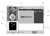
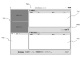
- a “returned tablet image discrimination” window 640 is displayed on the screen 531 as shown in FIG.
- Returned tablet image discrimination is used on the assumption that all the drugs to be identified are of the same type, but when different types of drugs are mixed, the user can easily mix different types of drugs.
- Various processes described below are performed so that the user can easily notice.
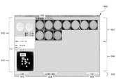
- the “returned tablet image discrimination” window 640 includes a first portion 641, a second portion 642, a third portion 643, a counting and message display portion 644, and an item display portion 645. It consists of.
- the user sets the tray 300 containing the medicine to be identified in the medicine imaging apparatus 200 and selects the “imaging” item 646.
- an image of the photographed medicine is displayed in the first portion 641. That is, in the first portion 641, an image obtained by photographing an area including a plurality of medicines is displayed.
- an image taken with the first light source 430 or the second light source 440 turned on is preferably used. This is because when an image is taken under such illumination, the contrast between the background and the medicine tends to increase.
- This image includes a region including a plurality of photographed drugs.
- a “view from above” tab and a “view from below” tab are provided.
- the computer 500 automatically counts the medicines and displays the counted number of medicines on the counting and message display portion 644. Further, the computer 500 displays a message 647 on the counting and message display portion 644. This message 647 prompts the user to select one medicine (representative medicine) from among the medicines displayed in the first portion 641. When the user selects one of the medicines (representative medicines) displayed in the first portion 641, the screen changes as shown in FIG. Depending on the setting, instead of the user, the computer 500 automatically selects one of the drugs displayed in the first portion 641 as a representative drug.
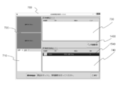
- an enlarged image of the selected representative medicine is displayed in the second portion 642.
- An image obtained by photographing the selected medicine from above is displayed on the upper portion of the second portion 642, and an image obtained by photographing the selected medicine from below is displayed in an enlarged manner on the lower portion.
- the computer 500 performs discrimination on the representative drug selected by the user or the computer 500. Further, in the first portion 641, a second label 648 is attached to the selected representative drug so that the representative drug selected by the user or the computer 500 can be easily understood.
- the computer 500 displays a list of drug information as candidates in the third portion 643.
- Each line in the list displays information on one candidate drug.
- the drugs that are more likely to be correct are displayed in the upper row of the list.
- the list display is sorted from top to bottom from the most likely drug to the lowest drug.
- the score obtained as a result of the search is used as an index to determine whether the possibility that the medicine is correct is high or low. Specifically, if the score of the possibility of matching with a medicine hit as a result of the search is high, the possibility that the medicine is correct is high, and if the score is low, the possibility of being correct is low.
- a score indicating the possibility that the candidate drug is correct an image of a drug stored in the database, a stamp or print code, and a drug name are displayed. If the setting is changed, instead of the score, the ranking of the possibility that this candidate drug is correct among all candidate drugs can be displayed. Furthermore, in addition to the drug name, a code (for example, YJ code) specifying the drug can also be displayed. In this way, when information related to one medicine is displayed together in one line, the user can easily understand. Moreover, you may display the dimension of a chemical
- the medicine image pointed to by the mouse cursor may be displayed in an enlarged manner.
- the medicine image that the user is interested in is immediately displayed. Become more visible.
- this makes it easy for the user to compare the medicine image displayed in the second portion 642 with the medicine image displayed in the third portion 643.
- the mouse cursor is moved away from the enlarged medicine image, the enlargement of the image is canceled and the medicine image returns to the original size.
- the user compares the drug displayed enlarged in the second portion 642 with the information of each candidate drug listed in the third portion 643, and selects the drug that the user determines to be correct.
- the user selects a medicine in the third portion 643, as shown in FIG. 10, the row showing the selected medicine is highlighted.
- a third indicator 652 indicating that the confirmation by the user is completed is attached to the corresponding medicine. In this state, the user selects the “differentiation start” item 651.
- FIG. 11 is a diagram showing a state where the user has selected the “start discrimination” item 651 shown in FIG.
- FIG. 11 shows a state where a returned tablet image discrimination is performed for a returned drug different from the returned drug shown in FIG.
- the second part 642 includes a master image of the medicine selected by the user in the third part 643 (a master image stored in the database corresponding to the selected medicine), and the name of the medicine. , Engraving (or printing), and the number of medicines are displayed.
- images obtained by enlarging the medicines displayed in the first portion 641 are displayed side by side.
- the size of the medicine measured by the computer 500 from the medicine image is displayed.
- the computer 500 further displays a message 659 in the third portion 643.
- This message 659 prompts the user to visually check the images of all the drugs displayed in the third portion 643.
- the user finds a different medicine as a result of visually confirming the image of the medicine displayed in the third portion 643, the user selects the medicine.
- the first portion 641 can be labeled with a drug corresponding to the different drug. Accordingly, the user can easily grasp where the different medicines are located on the tray 300, and can easily take out without mistake.
- the user can select the re-photographing item 654 to repeat the process of the above example.
- the image processing program of the present embodiment does not simply display the images of the plurality of medicines displayed in the first portion 641 side by side in the third portion 643 but also arranges the images of the plurality of medicines. It has a function to display instead. That is, the image processing program of the present embodiment, when a representative medicine is selected from a plurality of medicines displayed on the display device 530 (first portion 641), the image of the representative medicine and the display device 530 (first device). Template matching (also referred to as pattern matching) is performed between each of the images of the plurality of medicines displayed in the portion 641) and the similarity (matching rate) is obtained.
- Template matching also referred to as pattern matching
- the image of the representative medicine is an image photographed by the medicine photographing apparatus 200, and the images of each of the plurality of medicines are images photographed by the medicine photographing apparatus 200. Therefore, the image processing program obtains the similarity between images taken by the medicine photographing apparatus 200.
- the degree of similarity between images taken by the medicine imaging device 200 is obtained in such a manner that a pharmacist or the like can easily find out mixing of different kinds of medicines or the like when viewing a medicine image. This is because the images are rearranged. That is, the image processing program rearranges and displays the images of the plurality of medicines on the display device (third portion 643) based on the obtained similarity.
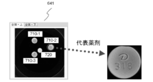
- FIG. 12 shows that four drugs are placed in the first portion 641, of which three drugs 710-1, 710-2, and 710-3 are of the same type and the remaining drug 720 is of a different type. is there. Further, the medicines 710-1, 710-2 and the medicine 720 are placed facing the front, and the medicine 710-3 is placed facing the back. In this case, it is assumed that the medicine 710-2 is selected as a representative medicine by the user.
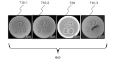
- each medicine is in the third part. 643 are displayed side by side. Specifically, the medicine 710-1 positioned at the top in the first portion 641 is displayed on the leftmost side in the third portion 643. In addition, the medicine 710-2 positioned second from the top in the first portion 641 is displayed second from the left in the third portion 643. The medicine 720 located third from the top in the first portion 641 is displayed third from the left in the third portion 643. The medicine 710-3 located at the lowest position in the first portion 641 is displayed on the rightmost side in the third portion 643.
- images of a plurality of medicines are rearranged (sorted) in ascending order of similarity obtained by the template matching, and the display device (third portion) 643). That is, since the medicine 710-1 is the same kind as the medicine 710-2 which is the representative medicine, the similarity to the medicine 710-2 is as high as about 0.9133. Since the medicine 710-2 itself is selected as the representative medicine, the similarity according to the template matching is 1. On the other hand, the medicine 710-3 is the same kind as the medicine 710-2 which is the representative medicine, but the surface has dirt attached, so the similarity to the medicine 710-2 is slightly lowered to about 0.8072. Further, since the medicine 720 is of a different type from the medicine 710-2 that is the representative medicine, the similarity to the medicine 710-2 is zero.
- the image processing program of the present embodiment displays the medicine 720 having the lowest similarity on the leftmost side of the third portion 643. Further, the image processing program displays the medicine 710-3 having the second lowest similarity second from the left of the third portion 643. Further, the image processing program displays the medicine 710-1 having the third lowest similarity third from the left of the third portion 643. Further, the image processing program displays the medicine 710-2 having the highest degree of similarity on the rightmost side of the third portion 643.
- an example is shown in which images of a plurality of medicines are rearranged and displayed on the display device (third portion 643) in descending order of similarity, but the present invention is not limited to this.
- the image processing program can rearrange images of a plurality of medicines in descending order of similarity and display them on the display device (third portion 643).
- the user can easily find different types of drugs. . That is, in the example of FIG. 14, a plurality of medicines are rearranged and displayed in order of decreasing similarity, and therefore, different kinds of medicines are likely to be displayed on the left side in the third portion 643. Therefore, the user can easily find different types of drugs by paying attention to the drug located on the left side in the images of the plurality of drugs displayed in the third portion 643. As a result, according to the present embodiment, the accuracy of drug discrimination can be improved, and the returned drug can be safely reused.
- the pharmacist or the like may sort the returned medicines into the same kind of medicine by visual observation, but there is a possibility that the different kinds of medicines may not be noticed only by visual inspection of the medicine.
- the pharmacists and the like can easily notice mixing of different types of drugs, Different types of drugs can be removed.
- the drug with dirt attached has a relatively low similarity to the representative drug, and thus may be displayed on the left side in the third portion 643.
- the user can easily find a drug with dirt attached by paying attention to the left side of the third portion 643.
- the accuracy of drug discrimination can be improved, and the returned drug can be safely reused.
- Returning the returned medicine to the original container or tablet packaging machine or the like for reuse requires considerable care and high-precision discrimination.
- a medical institution that gives priority to safety and discards the returned drug Is also present.
- a countermeasure against the recent increase in medical costs such disposal is a major social problem, and the countermeasure is urgently required.
- the present embodiment it is possible to easily find different types of drugs and drugs with dirt attached thereto, so that high-precision drug discrimination can be realized. As a result, the returned drug can be safely reused, which can be an effective measure against the recent increase in medical costs.
- the image processing program 600 of the present embodiment has a function of aligning the directions of a plurality of medicines when displaying a plurality of medicine images on the third portion 643.
- the image processing program 600 displays a plurality of medicine images on the display device (third portion 643) so that the directions of the plurality of medicine images are aligned with the representative medicine as a reference.
- the image processing program 600 rotates the orientation of the medicine 710-2 selected as the representative medicine in a direction that is easy for the operator to see (the letters D and numbers 318 on the medicine table are easy to read). .
- the image processing program 600 rotates the direction of the other medicine so that the orientation is the same as that of the medicine 710-2.
- the image processing program 600 of the present embodiment has a function of aligning the front and back of a plurality of medicines when displaying a plurality of medicine images on the third portion 643.
- the image processing program 600 displays a plurality of medicine images on the display device (third portion 643) so that the front and back of the plurality of medicines are aligned with reference to the front and back of the medicine in the representative medicine image.
- the image processing program 600 sets the third part with the medicine 710-2 facing up so that the operator can see the letter D and the number 318 of the medicine 710-2 selected as the representative medicine. 643. Then, the image processing program 600 displays other medicines on the third portion 643 facing the front in the same manner as the medicine 710-2.
- the medicine 710-3 was originally displayed face-down on the first part 641, but by this processing, it is displayed face-up on the third part 643.
- the operator can easily confirm whether different types of tablets are mixed.
- the learning function of the discrimination process of returned goods medicine can also be provided.
- the image discrimination of brought medicines since various medicines are brought in, there is a specification that a photographed tablet is newly learned and set as a master.
- the returned drug image discrimination unlike a brought-in drug, a master already exists, so the specification of further learning and resetting as a master was not originally required.
- a medicine with few scratches and dirt is selected as the representative medicine among the photographed medicines.
- a medicine with less scratches and dirt than the master may be selected as a representative medicine. If this medicine can be learned as a master, the processing accuracy in drug image discrimination can be increased.
- a specification is added that rearranges the similarities obtained by the template matching described above in ascending order or descending order. Then, the score that matches the currently registered master with a plurality of other drugs is compared with the score that matches the drug selected as the representative drug with the other drugs. If the average value of both scores is compared and the average value of the representative drug is higher, it can be judged that the representative drug is superior to the master currently used.
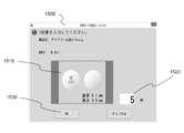
- the display device 530 displays an announcement as to whether or not the representative drug is to be replaced with the currently used master (learns master information). Specifically, a message prompting to update the learning data is displayed in the “Returned Tablet Image Identification” window 640, and the operator confirms the matching similarity score and decides whether or not to update the master information by learning. can do. Thereby, when a medicine with less scratches and dirt than the master is selected as the representative medicine, it can be continuously learned and updated as the master, so that the processing accuracy in the drug image discrimination can be continuously improved. .
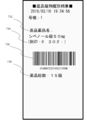
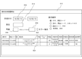
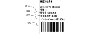
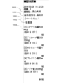
- FIG. 15 is a diagram illustrating an example of a printed returned-goods medicine discrimination result.
- the image processing program 600 recognizes the names of the returned medicines 732, the stamp 734, the barcode 736 (for example, GS1 code), and the total number of returned medicines 738, as shown in FIG. Etc. are printed on a medium (for example, paper).
- the image processing program 600 prints the discrimination result on a medium including an identifier indicating that the plurality of medicines are returned and identified.
- the image processing program 600 prints on a medium including an identifier indicating that a plurality of drugs have been returned and identified in the part indicating the drug lot number in the barcode 736.
- the image processing program 600 can print on the medium including the total number 740 of returned medicines in the barcode 736 as a result of identifying a plurality of medicines. Specifically, the image processing program 600 adds the total number 740 of returned medicines to the last four digits of the barcode 736 and prints it on the medium. According to this, when filling the returned medicine tablet into the medicine packaging device, the total number of returned medicines can be reflected in the medicine packaging device by reading the barcode 736 with the barcode reader of the medicine packaging device. Therefore, it is possible to save the trouble of manually inputting the total number of returned medicines.
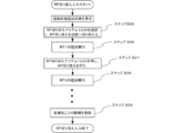
- the image processing program 600 can print the total drug price 742 of a plurality of identified drugs as a result of identifying a plurality of drugs. Specifically, the image processing program 600 calculates the total drug price of a plurality of identified drugs by multiplying the number of tablets (740 in total) of the identified drugs and the price of each of the drugs. The total drug price 742 is printed on the medium.
- the comprehensive drug database “MD bank” (trademark) manufactured by Yuyama Manufacturing Co., Ltd. is installed in the computer 500, the price of each of the identified drugs is obtained by referring to the MD bank. However, it is not limited to this.
- FIG. 21 is a diagram showing an example of an environment setting screen for setting whether or not to print the number of identified medicines and the total drug price.
- the environment setting screen 744 displays a lock number printing check box 746 and a drug price printing check box 748.
- the image processing program 600 prints the total number 740 of returned medicines on the medium when printing the discrimination result.
- the image processing program 600 prints the total drug price 742 of a plurality of identified drugs on the medium when printing the discrimination result.
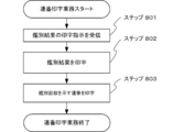
- FIG. 16 is a flowchart of processing executed by the image processing program.
- the image processing program 600 photographs an image of a region including a plurality of medicines by using the medicine photographing apparatus 200 (step 101).
- the image processing program 600 receives an image photographed by the medicine photographing apparatus 200 by the receiving unit 510 (step 102).
- the image processing program 600 displays the received image on the first portion 641 (step 103).
- the image processing program 600 displays an enlarged image of the representative medicine image on the second portion 642 (step 104).
- the representative drug can be arbitrarily selected by the image processing program 600 from a plurality of drugs.
- the image processing program 600 displays information on a drug that is a candidate for identifying a representative drug in the third portion 643 (step 105). Subsequently, when a drug determined to be correct by the operator is selected from candidate drugs, the image processing program 600 reads a master image of the selected drug from the database and displays it in the second portion 642. (Step 106).
- the image processing program 600 obtains the similarity between the representative medicine image and each of the plurality of medicine images displayed in the first portion 641 (step 107). Subsequently, the image processing program 600 rearranges the images of the plurality of medicines based on the obtained similarity and displays them on the third portion 643 (step 108). Note that when the image processing program 600 rearranges the plurality of images in step 108 and displays them on the third portion 643, the plurality of drugs are arranged so that the directions of the plurality of drugs are aligned with reference to the representative drug image. Images can be displayed.
- the image processing program 600 rearranges the plurality of images in step 108 and displays them on the third portion 643, the front and back of the plurality of medicines are aligned based on the front and back of the representative medicine in the representative medicine image. Images of a plurality of drugs can be displayed.
- the image processing program 600 is Then, the discrimination result of the returned medicine is printed (step 109).
- the operator can fill the medicine packaging apparatus with the returned tablets using the medium on which the discrimination result of the returned tablets is printed.
- FIG. 22 is an example of an image image in discrimination of a brought-in drug.
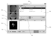
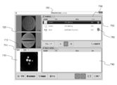
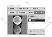
- a “tablet image discrimination” window 700 as shown in FIG. 22 is displayed on the display device 530.
- the “tablet image discrimination” window 700 is roughly divided into a first portion 710, a second portion 720, a third portion 730, and a fourth portion 740.
- an image photographed by the medicine photographing apparatus 200 is displayed.
- an image taken with the first light source 430 or the second light source 440 turned on is preferably used. This is because when an image is taken under such illumination, the contrast between the background and the medicine tends to increase.
- This image includes a region including a plurality of photographed drugs.
- a “view from above” tab 711 and a “view from below” tab 712 are provided at the top of the first portion 710. When the user selects the “view from above” tab 711, an image of the medicine taken from above is displayed in the first portion 710. When the “view from below” tab 712 is selected, an image obtained by photographing the medicine from below is displayed in the first portion 710.
- the computer 500 When the computer 500 acquires the captured image, the computer 500 automatically recognizes the area occupied by each medicine based on the image.
- an image of the selected medicine is enlarged and displayed in the second portion 720.
- an image obtained by photographing the selected medicine from above is displayed, and in the lower part, an image obtained by photographing the selected medicine from below is displayed in an enlarged manner.
- the selection of the medicine is automatically performed by the computer 500 from the medicines that have been identified.
- the computer 500 displays a list of candidate drugs obtained as a result of the identification in the third portion 730.
- Each line in the list displays information on one candidate drug.
- Each row in the list displays drug images, inscriptions, drug names, scores, and the like stored in the database as candidate drug information.
- the user compares the drug displayed enlarged in the second portion 720 with the information on each candidate drug listed in the third portion 730, and selects the drug that the user determines to be correct. Specifically, the user selects a line in the third portion 730 where correct drug information is displayed. Thereafter, when the user is convinced that the medicine selected by the user is the correct medicine, the user selects the “select” item 761. Then, information on the selected medicine is added to the fourth portion 740. When the confirmation of one medicine is completed, the user selects another medicine that has not yet been confirmed in the first portion 710, and performs the same procedure as described above for this selected medicine. Confirmation work is performed.
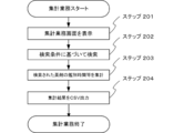
- FIG. 23 is a flowchart of a task of counting work time and cost required for drug discrimination.
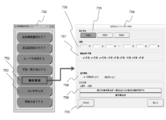
- 24 and 25 are diagrams illustrating an example of a screen for performing aggregation relating to drug discrimination.
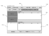
- the tablet identification menu window 750 includes a “counting work” item 752.
- the image processing program 600 displays the total operation screen 754 on the display device 530 (step S 201).
- a totaling unit 755 As a search condition for performing the totaling work, a totaling unit 755, a period 756, an extraction condition (unit) 757, an output unit 758, an output target 759, and a “CSV output” item 760 are displayed. Is displayed.
- the user can select at least one of “day designation”, “month designation”, and “year designation” in the aggregation unit 755.
- the user can designate a period for performing a task of totaling work time and cost required for drug discrimination in the period 756.
- the user can specify the number of the device that is the target of the totaling work in the extraction condition (numbered machine) 757.
- the user can select, in the output unit 758, whether to output the total result “by user” or “output by day of the week”.
- the user can designate the output target of the total result as “discrimination” or “return” in the output target 759.
- FIG. 24 shows an example of the case where “differentiation” is designated, and it is possible to output the total result of the identification when specifying the medicine brought by the patient.
- FIG. 25 is an example when “returned goods” is designated, and it is possible to output a totaling result of discrimination when specifying returned medicines.
- the user can input the extraction condition (medicine) 763 as a search condition.
- the user can input a medicine name and / or a stamp name as a search condition in the extraction condition (medicine) 763.
- the image processing program 600 searches based on the search conditions input via the totaling work screen 754. The result of drug discrimination that matches the conditions is searched (step S202).
- the image processing program 600 aggregates the discrimination time, cost, and the like based on the searched drug discrimination result (step S203). For example, the image processing program 600 measures the discrimination time required to discriminate a drug, and totals the measured discrimination time or the discrimination time per drug tablet. Further, the image processing program 600 measures the discrimination time required to discriminate a plurality of drugs, and totals the measured discrimination time and the total drug price of the plurality of discriminated drugs. Good.
- the image processing program 600 performs CSV output based on the counting result (step S204). Specifically, when “discrimination” is designated in the output target 759, the image processing program 600 totals the total discrimination work time, the average discrimination work time per medicine, the number of discrimination medicines, and the like. Then, a CSV (Comma Separated Values) file is generated and stored in a storage device or the like. As described above, by collecting the time required for the discrimination of the medicine brought by the patient and outputting the CSV, the user can easily understand how much time is required for the medicine discrimination.
- CSV Common Separated Values
- the image processing program 600 totals the total return work time, the average return work time per time, the number of returned medicines, the total drug price, etc. Create a (Comma Separated Values) file and save it in a storage device. In this way, by summing up the work time and total drug price related to the discrimination of returned medicines and outputting them in CSV format, the user needs to know how much time is required for returning medicines, and how much drug price is determined by drug discrimination. It will be easier to see if it has been reduced.
- FIG. 26 is a diagram illustrating an example of a totaling result screen such as identification time required for identifying a medicine.
- a totaling result screen such as identification time required for identifying a medicine.
- the user can select a user information search item 765, a patient information search item 767, and a medicine information search item 769 as a search condition for performing the tabulation work.
- the user can input a user ID or a user name as a search key in the user information search item 756.
- the user can input a patient ID or a patient name as a search key in the patient information search item 758.
- the user can input a medicine name or a stamp name as a search key in the medicine information search item 760.
- the image processing program 600 displays on the display device 530 the totaled result that is totaled based on the search condition input via the user information search item 765, the patient information search item 767, or the medicine information search item 769. Can do.
- the total result screen 762 includes an average discrimination time 764 per medicine, an average discrimination time 766 per day, an average number of medicines 768 per day, and search conditions.
- a list 770 of corresponding discriminations is displayed.
- the identification list 770 includes identification number, the number of the drug imaging apparatus 200 that has performed imaging of the drug, the date of the identification, the name of the user who performed the identification, the name of the patient who brought the drug, and the number of drugs identified The time required for the discrimination, the web discrimination interlocking number, and the like are displayed.
- the time required for discrimination is the time from when a medicine is newly photographed by the medicine photographing apparatus 200 until it is registered for differentiation (for example, until the “Register” item 754 is selected), and is measured by the image processing program 600. Is done. In this way, by counting the time required for the medicine discrimination and displaying it on the display device 530, the user can easily understand how much time is required for the medicine discrimination.
- FIG. 27 is a diagram illustrating an example of a totaling result screen such as identification time required for identifying a drug.
- FIG. 27 is an example of a totaling result screen such as a discrimination time required for discrimination of a plurality of returned drugs when the “returned tablet image discrimination” item 622 is selected.
- the total result screen 762 includes an average work time 772 per returned work, an average work time 774 per day, an average number of returned medicines 776 per day, a drug price (total price) ) 778 and a list of discriminations 780 corresponding to the search condition are displayed.
- the discrimination list 780 the identification number, the number of the drug imaging device 200 that performed imaging of the drug, the date of the identification, the name of the user who performed the identification, the name of the drug returned by the identification, and the returned by identification.
- the number of drugs, the time required for the discrimination, the drug price (total) of the drugs returned by the discrimination, etc. are displayed.
- the time required for discrimination is the time from when a medicine is newly photographed by the medicine photographing apparatus 200 until it is registered for differentiation (for example, until the “print” item 653 is selected), and is measured by the image processing program 600. Is done. In this way, by counting the time required for drug discrimination and the drug price of the drug returned by the discrimination and displaying it on the display device 530, the user needs to know how much time is required for the drug discrimination. Therefore, it becomes easy to grasp how much the drug price can be reduced by the drug discrimination.
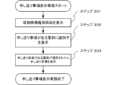
- FIG. 28 is a flowchart of the sending item display job.
- FIG. 29 to FIG. 31 are diagrams showing an example of a state in which a report item relating to drug discrimination is displayed.
- the image processing program 600 displays a “tablet image identification” window 700 as shown in FIG. The information is displayed on the display device 530 (step S301).
- an image photographed by the medicine photographing apparatus 200 is displayed.
- an image of the selected medicine is enlarged and displayed in the second portion 720.
- an image obtained by photographing the selected medicine from above is displayed, and in the lower part, an image obtained by photographing the selected medicine from below is displayed in an enlarged manner.
- the selection of the medicine is automatically performed by the computer 500 from the medicines that have been identified.
- the computer 500 displays a list of candidate drugs obtained as a result of the identification in the third portion 730.
- Each line in the list displays information on one candidate drug.
- Each row in the list displays drug images, inscriptions, drug names, scores, and the like stored in the database as candidate drug information.
- a notification item is included in the candidate drug.
- an identifier 782 indicating that there is a report item is displayed on the display device 530 (step S302).
- three candidate drugs are displayed in the third portion 730, and it is shown that there are items to be reported for two drugs.
- the identifier 782 is not displayed, it indicates that there is no report item.
- the image processing program 600 displays a notification item 784 when a candidate drug or identifier 782 is selected or when the mouse cursor moves near the candidate drug or identifier 782.
- the information is displayed on the device 530 (step S303).
- the medicine image pointed to by the mouse cursor is enlarged and a delivery item 784 is displayed.
- the delivery item 784 the selected medicine has a plurality of standard differences.
- the sending item 784 can display various items depending on the medicine, such as the fact that there are a plurality of different standards, and there are a plurality of different markings on the back surface. Further, when the “returned tablet image discrimination” item 622 is selected, various items to be sent can be displayed such as, for example, LASIX changes color and is discarded without being returned.
- the image displayed on the third portion 730 is enlarged according to the operation of the user, the image of the medicine that the user is interested in immediately can be seen in detail.
- this makes it easy for the user to compare the medicine image displayed in the second part 720 with the medicine image displayed in the third part.
- the mouse cursor is moved away from the enlarged medicine image, the enlargement of the image is canceled and the medicine image returns to the original size.
- the user compares the drug displayed enlarged in the second portion 720 with the information on each candidate drug listed in the third portion 730, and selects the drug that the user determines to be correct.
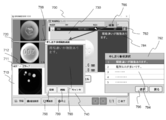
- an identifier 782 indicating that there is a notification item in the candidate medicine is displayed on the display device 530, and further, a notification item 784 is displayed on the display device 530.
- the correct medicine can be selected in consideration of the contents of the delivery item 784.
- FIG. 32 is a diagram illustrating an example of a screen for editing a notification item related to drug discrimination.
- a menu screen 786 is displayed on the display device 530.
- a menu of “edit” is displayed on the menu screen 786.
- a menu of “registration” is displayed on the menu screen 786.
- a message entry screen 788 is displayed on the display device 530.
- the user can manually fill in the entry items in the entry field 790 of the entry item entry screen 788.
- a report item selection screen 792 is displayed on the display device 530.
- a pre-registered offer item list 794 is displayed on the display device 530.
- FIG. 32 shows an example in which two items to be sent are registered in advance, but the number of items to be pre-registered is arbitrary.
- the user can reflect the selected sending item in the entry field 790 by selecting an appropriate item from the sending item list 794 and clicking the selection item 796.
- the user can set the notification item described in the entry field 790 as the notification item of the candidate drug by clicking the registration item 798 on the notification item entry screen 788.
- the user can delete the notification item 784 set in the candidate medicine by clicking the deletion item 799 on the notification item entry screen 788.
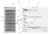
- FIG. 33 is a flowchart of a patient information input task.
- FIG. 34 is a diagram illustrating an example of a state in which information related to a patient of a brought-in drug is displayed on a screen for performing drug discrimination.
- the image processing program 600 causes the computer 500 to execute a step of displaying on the display device 530 a discrimination screen for discriminating the patient's brought-in drug when the drug brought by the patient is differentiated (step S401).
- a “tablet image discrimination” window 700 is displayed on the display device 530.
- the “tablet image discrimination” window 700 displays patient information in addition to the first part 710, the second part 720, the third part 730, and the fourth part 740.
- a fifth portion 1100 is displayed.
- the patient name, sex, ward, department, etc. are displayed as information on the patient who brought the medicine to be identified.
- the fifth portion 1100 is provided with a patient attribute item 1102.
- the image processing program 600 causes the computer 500 to execute a step of accepting input of information related to the patient who brought the medicine through the discrimination screen displayed on the display device 530 (step S402). Specifically, when the patient attribute item 1102 is clicked by the user, the image processing program 600 displays a screen (attribute input screen 1110) for inputting patient attributes.
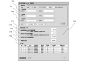
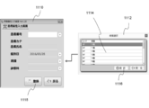
- FIG. 35 is a diagram illustrating an example of a screen for inputting attributes of a patient who brought a medicine. Information such as a patient number, patient name, identification date, ward, and department can be entered on the attribute input screen 1110.
- the attribute input screen 1110 can reflect the patient information registered in the database to the attribute input screen 1110 when the user inputs the patient number. It is like that.
- the attribute input screen 1110 allows the user to edit patient information reflected from the database. For example, when the user places the mouse cursor on a field for inputting a ward and clicks the Enter key on the keyboard, a ward selection screen 1112 is displayed on the display device 530. A ward list 1114 registered in advance is displayed on the ward selection screen 1112. When the user selects an appropriate item from the ward list 1114 and clicks the selection item 1116, the selected ward is reflected on the attribute input screen 1110. Items other than the ward can also be selected from the list.
- the attribute input screen 1110 allows the user to input patient information manually on the attribute input screen 1110. When the registered item 1118 on the attribute input screen 1110 is clicked, the image processing program 600 displays the patient information input on the attribute input screen 1110 on the fifth portion 1100 (step S403).
- FIG. 36 is a diagram illustrating an example of a screen for inputting attributes of a patient who brought a medicine. If the patient information is not registered in the database, the patient information can be registered via the patient information registration screen 1120 shown in FIG.
- the patient information registration screen 1120 is provided with columns for registering items such as a patient number, patient name, date of birth, and sex. The user can newly register patient information in the database by inputting patient information in each item and clicking the registration item 1122.
- the image processing program 600 causes the computer 500 to execute a step of associating information about the patient who brought the medicine with the discrimination result of the brought medicine (step S404).
- the image processing program 600 can store the result of identifying the medicine brought by the patient and the patient information in a storage device or the like in association with each other. Thereby, for example, it is possible to search the discrimination result of the medicine brought by the patient using the patient information such as the patient name as a search key, so that the convenience for the user can be improved.
- FIG. 37 is a flowchart of usage input work.
- FIG. 38 is a diagram showing an example of a discrimination screen for discriminating drugs brought by patients.
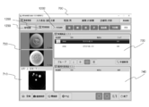
- the image processing program 600 causes the computer 500 to execute a step of displaying on the display device 530 a discrimination screen for discriminating the patient's brought-in drug when the drug brought by the patient is differentiated (step S501).
- a “tablet image discrimination” window 700 is displayed on the display device 530.
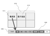
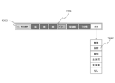
- an RP switching item 1230 is provided.
- a sixth portion that displays usage information 1200 is provided.
- the sixth portion 1200 information on the usage of the medicine to be identified is displayed.
- the sixth part 1200 is provided with a usage selection item 1202.
- the image processing program 600 causes the computer 500 to execute a step of accepting input of information regarding the usage of the medicine brought by the patient via the “Tablet Image Identification” window 700 displayed on the display device 530 (Step S502). Specifically, when the usage selection item 1202 is clicked by the user, the image processing program 600 activates (displays) a screen for selecting a usage.
- FIG. 39 is a diagram showing an example of a screen for inputting the usage of the medicine brought by the patient via the discrimination screen for identifying the medicine brought by the patient.
- the usage selection screen 1210 when the user selects, for example, the “after meal” item 1212, a check mark is added to the items “morning”, “noon”, and “evening” in the sixth portion 1200, and “after eating” "Becomes active.
- the “after dinner” item 1214 a check mark is added to the “morning” and “evening” items in the sixth portion 1200, and the “after dinner” item becomes active.
- FIG. 40 is a diagram illustrating an example of a screen for inputting the usage of the medicine brought by the patient via the discrimination screen for differentiating the medicine brought by the patient.
- a usage list 1220 is displayed.
- the usage list 1220 displays usage types such as “after meal”, “before meal”, “between meals”, “just before meal”, “immediately after meal”.
- the user can reflect the selected usage in the sixth portion 1200 by selecting any usage from the usage list 1220.
- the usage can be input via the “Tablet Image Identification” window 700, so that it is possible to save the user's trouble concerning the input setting of the usage.
- the image processing program 600 causes the computer 500 to execute a step of associating information regarding the usage of the drug brought by the patient with the discrimination result of the carried drug (step S504). Specifically, the image processing program 600 associates the result of drug discrimination brought by the patient with the usage of the drug and saves it in a storage device or the like, or prints the result of the discrimination and the drug method on a medium. can do.
- the setting is such that the activation and inactivation of the RP switching can be switched.
- the user can specify and switch the RP so that the medicine prescribed for each of the plurality of hospitals can be identified and managed.
- FIG. 41 is a flowchart of RP switching.
- the system of the discrimination report in which the discrimination data is transmitted from this apparatus it is designed so that the style of the report can be freely processed.
- a medicine brought by a patient has a remaining amount of 20 tablets in the morning, 10 tablets in the day, and 10 tablets in the evening as prescribed by the hospital A.
- An operation method and a data input method will be described below by taking, as an example, a case in which the amount prescribed by the hospital B is 5 tablets in the morning and 5 tablets in the evening.
- the image processing program 600 starts RP switching input.
- the tablet image discrimination screen set for each Rp is displayed, and the discrimination work is started (steps 506 to 508).
- the work starts by first identifying 20 tablets for Rp1 morning in the petri dish. Then, the morning identification of Rp1 is completed by pressing the morning of the usage selection button. Then, the medicine used for the discrimination is removed, and then 10 tablets for daytime are placed. After the additional shooting button is pressed, the day of the usage selection button is pushed, and then 10 tablets for evening are placed. Press the additional shooting button, then press the usage selection button evening.
- the Rp switching button is pressed to shift to the prescription of hospital B (step 903). If there is a remaining amount of 5 tablets in the morning and 5 tablets in the evening as a medicine from hospital B, 5 morning medicines are placed, the additional photographing button is pushed, and the usage selection button morning is pushed after photographing. Next, 5 tablets for the evening are placed, the additional photographing button is pushed, and the evening of the usage selection button is pushed. In this manner, the medicine discrimination from the hospital B is completed (step 508). After all the discrimination is completed, the patient information for each hospital can be newly registered in the database by clicking the registration item 1122 (step 509).
- data is transmitted for each operation performed in the above-described operation, that is, for each Rp, for each petri dish, and for each usage. It becomes possible to do.
- the operations of steps 506 to 508 are similarly executed as hospitals C, D, E.
- the petri dish has a maximum capacity of only 15 tablets, for example, when distinguishing 20 tablets for morning use as described in the embodiment of FIG. 41, 15 tablets are first placed on the dish. And press the new shooting button to execute shooting. Then, 15 tablets are taken out and the remaining 5 tablets are placed on the petri dish. After placing the remaining 5 tablets on the petri dish, next press the additional shooting button.
- the drug discrimination system 100 can be set so that the discrimination operation is continued.
- FIG. 42 is a flowchart of maintenance work.
- the image processing program 600 causes the computer 500 to execute a step of displaying a menu image related to drug identification on the display device 530 (step S601).
- the tablet identification menu window 750 in FIGS. 24 and 25 is displayed on the display device 530.
- the image processing program 600 causes the computer 500 to execute a step of accepting a setting item change input related to drug discrimination via the window 750 of the tablet discrimination menu (step S602).
- FIG. 43 is a diagram illustrating an example of a screen for changing settings relating to drug discrimination.
- the setting change screen 1300 displays a function setting item 1310 for setting use / non-use of various functions related to drug discrimination.
- usage setting item 1320 for setting the usage of the drug is displayed on the setting change screen 1300. Is displayed. The user can set use / nonuse of various functions by clicking an item for setting various functions in the function setting item 1310. Also, when the usage registration screen activation item 1322 in the usage setting item 1320 is clicked, the usage registration screen 1330 is activated (displayed).
- FIG. 44 is a diagram illustrating an example of a screen for registering drug usage.
- a usage registration item 1332, a registered item 1334, a list 1336, a confirmed item 1338, and a deleted item 1340 are displayed on the usage registration screen 1330.
- the user wants to register the usage after each meal, check the “morning”, “noon”, and “evening” items in the usage registration item 1332 so that the item “after eating” is activated.
- the registered item 1334 is clicked.
- the usage “after every meal” is displayed in the list 1336.
- the image processing program 600 registers the changed setting item, that is, the usage “after each meal” (step S603).
- the number of registrations is arbitrary. For example, when the user checks the items “morning” and “evening”, changes the item “after meal” to the item “before meal”, and clicks the registered item 1334, the usage “before morning dinner” is changed. You can register. Also, when the user places the mouse cursor on a usage that has already been registered and clicks on the delete item 1340, the usage is deleted and that portion of the list 1336 becomes blank. According to the present embodiment, the user can easily change various settings such as drug usage via the window 750 of the tablet identification menu.
- FIG. 45 is a flowchart of the manual search operation for a differential medicine.
- the image processing program 600 causes the computer 500 to execute a step of displaying a discrimination screen for identifying the medicine on the display device 530 (step S701).
- a “tablet image discrimination” window 700 as shown in FIG. 46 is displayed on the display device 530.
- FIG. 46 is a diagram illustrating an example of a screen for manually searching for drugs through a discrimination screen for identifying drugs.
- a screen for manually searching for a medicine is activated.
- a “manual search” item 1400 is provided.
- the image processing program 600 causes the computer 500 to execute a step of displaying a screen for manually searching for drugs on the display device 530 via the “tablet image discrimination” window 700 (step S702). Specifically, when the operator clicks the “manual search” item 1400, the image processing program 600 displays a medicine search screen 1410 shown in FIG. 47 on the display device 530.
- FIG. 47 is a diagram illustrating an example of a screen for manually searching for medicines.
- a search condition input item 1420 As shown in FIG. 47, on the medicine search screen 1410, a search condition input item 1420, a medicine display item 1430, a search result display item 1440, an additional item 1450, and a delivery item display item 1460 are displayed.
- “engraved” or “medicine name” can be selected as a condition for searching for a medicine. The operator selects either “engraved” or “medicine name”, inputs search conditions in the search box 1422, and clicks the search item 1424. Then, in the search result display item 1440, a list of medicines that match the search condition is displayed. When the worker selects any medicine from the list of search result display items 1440, an image of the selected medicine is displayed on the medicine display item 1430.
- an identifier 1441 indicating that there is a sending item is displayed for a medicine for which the sending item is set.
- the sent items of the selected medicine are displayed in the sent items display item 1460. For example, when a medicine for which a notification item is registered for a specific medicine is selected in the search result display item 1440 via the notification item entry screen 788 in FIG. Is displayed.
- the sending item display item 1460 is provided with a sending item editing item 1462.
- the worker can edit the notification item already set for the selected medicine by clicking the notification item editing item 1462.
- the worker can set a new report item by clicking on the report item editing item 1462 if no report item is set for the selected medicine.
- FIG. 48 is a diagram illustrating an example of a screen for manually searching for medicines.
- a drug display item 1510 for displaying an image of the selected drug a lock number input item 1520 for inputting the number of drug locks, and a fourth drug are displayed.
- An “OK” item 1530 to be added to the portion 740 is displayed.
- FIG. 49 is a diagram illustrating an example of a state in which a manually searched medicine is displayed on the discrimination screen as a discrimination result. As shown in FIG. 49, in the fourth portion 740 of the “Tablet Image Discrimination” window 700, the manually searched medicine 1540 is displayed as the discrimination target medicine together with the number of tablets.
- FIG. 50 is a flowchart of the serial number printing job.
- 51 and 51 are diagrams illustrating an example of a printed medicine discrimination result.
- FIG. 51 shows an example of a drug discrimination result when a barcode barcode product identifier (AI code) addition setting 749 in the environment setting screen 744 of FIG.
- FIG. 52 is an example of the drug discrimination result when the barcode barcode product identifier (AI code) addition setting 749 in the environment setting screen 744 of FIG.
- the image processing program 600 receives a signal for printing the identification result (step S801). Upon receiving the print instruction signal, the image processing program 600 prints the medicine discrimination result on the medium (step S802), and prints and outputs an identification number for identifying the result of the medicine discrimination on the medium (step S802). S803). Specifically, as shown in FIG. 51, in addition to the patient name 1610 and the discriminator 1620, a barcode No. 1630, a barcode 1640, and the like are printed on the medium.
- the machine No. (1 digit), the identification date (4 digits), and the serial number (3 digits) of the apparatus that performed the discrimination are output. Since the serial number is a number that is sequentially assigned each time the drug discrimination is performed, the role of the ID number for uniquely identifying each drug discrimination (drug discrimination result) while indicating the number of times the drug discrimination has been performed Fulfill. Further, the barcode No. 1630 includes the content of the barcode No. 1630 and the content of the discrimination result. For the discriminator 1620 printed on the medium, the name of the person who logs in to the system for performing drug discrimination is printed. According to the present embodiment, it is possible to easily call a discrimination result or the like in WEB discrimination simply by scanning the barcode 1640 with a barcode reader.
- the barcode barcode product identifier (AI code) addition setting 749 on the environment setting screen 744 in FIG. 21 is set so as not to add a barcode
- the patient name 1610 is included in the medium as shown in FIG.
- the petri dish No. 1650, the usage 1652, and the discrimination drug list 1654 are printed.
- the petri dish number 1650 is printed with the petri dish number used in the discrimination
- the usage 1652 is printed with the medicine usage set in FIGS. 38 to 40, for example.
- the medium without a barcode as shown in FIG. 52 can show the discrimination result in an easy-to-understand manner, for example, by pasting it on the wrapping paper after the discrimination of the medicine is completed. According to this embodiment, since two types of discrimination results as shown in FIGS. 51 and 51 can be printed according to the work purpose, the efficiency of the operator's discrimination work can be improved.
- FIG. 53 is a diagram for explaining the drug region editing function.
- the present invention is not limited to this. For example, it is possible to perform drug region editing even when identifying returned drugs, and to perform drug region editing even when not all of the drug identification has been completed. it can.
- FIG. 53 is an enlarged view of a part of the “Tablet Image Identification” window 700 for convenience of explanation. As shown in FIG. 53, the “tablet image discrimination” window 700 displays an area edit item 1700.
- FIG. 54 is a diagram showing an example of the area editing screen.
- an image 1720 photographed by the medicine photographing apparatus 200, a “confirm” item 1730, and a “close” item 1732 are displayed on the region edit screen 1710.
- the computer 500 image processing program 600
- FIG. 54 shows an example when there is a medicine 1722 that is not automatically recognized by the computer 500.
- FIG. 55 is a diagram showing an example of the cut area editing screen.
- the cut area editing screen 1740 includes an “automatic rotation” item 1741, an “automatic rotation” item 1742, an “OK” item 1743, a “reset” item 1744, an “enlargement” item 1745, and a “reduction”.
- An item 1746, a “move” item 1747, a “rotate” item 1748, and a “cancel” item 1749 are displayed.
- An “automatic rotation” item 1741 is a button for rotating the display angle of the upper image obtained by photographing the medicine from above.
- An “automatic rotation” item 1742 is a button for rotating the display angle of the lower image obtained by photographing the medicine from below.
- FIG. 56 is a schematic diagram showing an example of drug region editing.
- the operator when the area 1752 of the medicine 1750 is not correctly recognized by the computer 500, the worker clicks the medicine whose area in the image 1720 is not correctly recognized. Then, the operator corrects the region 1754 of the medicine 1750 by appropriately adjusting the position, size, angle, and the like of the upper image and / or the lower image on the cut region editing screen 1740 and clicking the “OK” item 1743. can do.
- FIG. 56 (1) when the area 1752 of the medicine 1750 is not correctly recognized by the computer 500, the worker clicks the medicine whose area in the image 1720 is not correctly recognized. Then, the operator corrects the region 1754 of the medicine 1750 by appropriately adjusting the position, size, angle, and the like of the upper image and / or the lower image on the cut region editing screen 1740 and clicking the “OK” item 1743. can do.
- FIG. 56 is a schematic diagram showing an example of drug region editing.
- FIG. 17 is a schematic diagram showing an outline of the medicine packaging system of the present embodiment.
- the medicine packaging system 800 includes a medicine packaging apparatus 900 and a computer 500.
- the medicine packaging device 900 includes a display device 910 serving as an interface for outputting various information related to medicine packaging, and a barcode reader 920 for reading a barcode.
- the medicine packaging device 900 is connected to the computer 500.
- the receiving unit 510 of the computer 500 receives, for example, various information such as a history of medicines packaged in the medicine packaging apparatus 900 from the medicine packaging apparatus 900.
- the computer connected to the medicine packaging device 900 is the same as the computer 500 connected to the medicine imaging device 200, but is not limited to this and may be another computer.
- the worker fills the medicine packaging device 900 with the returned medicine using the barcode printed on the discrimination result shown in FIG. That is, the operator first scans the barcode printed on the discrimination result with the barcode reader 920. Subsequently, the operator scans the barcode printed on the medicine cassette to be filled with the returned medicine with the barcode reader 920. Thereby, the medicine packaging device 900 collates whether or not the type of the returned medicine matches the type of the medicine corresponding to the medicine cassette. Specifically, when the barcode of the target medicine is read by the barcode reader 920, a plurality of medicine cassettes are mounted on the medicine packaging device 900, so that the medicine cassette to be filled can be easily taken out by the operator.
- an RFID in which drug information is written is mounted on the drug cassette.
- the cassette is removed from the main body and placed on a cassette information reading unit (not shown) of the drug packaging device 900, the drug information is read from the RFID. Is read, and it is verified whether or not it matches the drug information on the barcode. As a result of the collation, when it is determined that the two match, the operator can fill the medicine cassette with the returned medicine.
- FIG. 18 is a diagram illustrating an example of an inquiry screen for a filling history of a medicine filled in the packaging device.
- the image processing program 600 displays a screen for inquiring the history of the medicine filled in the packaging device (medical filling history).
- An inquiry screen 810) is displayed on the display device 530.
- the user of the packaging device 900 inputs at least one of a medicine filling date 812, a medicine name 814, a packaging device number 816, a medicine cassette No. 818, etc.
- FIG. 18 shows an example in which a filling date is input as a search key, and it is searched that two medicines are filled on the date.
- the medicine filling history inquiry screen 810 may be displayed on the display device 910 provided in the packaging device 900.
- a medicine 822 in FIG. 18 is obtained by filling a packaging device with a new medicine instead of a returned medicine.
- the user of the packaging device can refer to the drug code, the name of the drug, the filling amount, the filling date and time, the filler, the expiration date, the serial number, and the like for the medicine 822.
- the medicine 824 is obtained by filling the packaged medicine with the returned medicine.
- the user of the packaging device can refer to the medicine code, the medicine name, the filling amount, the filling date and time, and the filling person.
- the letters “TAB” are displayed in the column of the production number.
- the characters “TAB” are characters indicating that the returned medicine is filled. By displaying such characters, the user of the packaging device can recognize that the medicine 824 is returned and identified by referring to the medicine filling history inquiry screen 810.
- the image processing program 600 associates the photographed image displayed in the first part 641 with the returned and identified medicine in the medicine filling history inquiry screen 810 and the plurality of images displayed in the third part 643. At least one of the medicine rearranged images can be displayed on the display device. That is, as shown in FIG. 19, when the user of the packaging apparatus moves and selects the mouse cursor 830 to the row of the medicine 824, the row of the medicine 824 is highlighted. Corresponding to the selection of the medicine 824, a “returned tablet image discrimination” window 640 when the medicine 824 is returned is displayed on the medicine filling history inquiry screen 810.
- the user of the packaging device can track what returned medicine is filled in the packaging device by referring to the “returned tablet image discrimination” window 640 on the medicine filling history inquiry screen 810. For example, when it is detected that an inappropriate medicine is filled in the packaging device, the stage in which the medicine is filled is tracked by referring to the “Returned tablet image discrimination” window 640. can do.
- the image processing program 600 displays at least one of the captured image displayed in the first portion 641 and the rearranged images of the plurality of drugs displayed in the third portion 643 on the drug filling history inquiry screen 810. Can do.
- Reference inventions are additionally described below.
- (Reference invention 1) A receiving unit that receives an image obtained by imaging a region including a plurality of drugs by a drug imaging device; A step of displaying on the display device an image of the region received by the receiving unit; and an image of the representative medicine selected from the plurality of medicines displayed on the display device and each of the plurality of medicines
- An image processing unit that executes a step of rearranging and displaying the images of the plurality of medicines on the display device based on the similarity to An image processing apparatus.
- (Reference invention 2) An enlarged image obtained by enlarging an image of the representative medicine in an image obtained by photographing the region, or a master image corresponding to the representative medicine is displayed on the display device;
- the image processing apparatus according to (Reference Invention 1), further executing (Reference invention 3)
- the image processing unit displays an image obtained by imaging the region on a first portion of the display device, displays the enlarged image or the master image on a second portion of the display device, and displays the plurality of medicines.
- the image processing device according to (Reference Invention 2) which displays an image in which images are rearranged on a third portion of the display device.
- (Reference invention 4) The image processing device according to any one of (Reference Inventions 1 to 3), wherein the image processing unit rearranges and displays the images of the plurality of medicines on the display device in descending order of the similarity. .
- (Reference invention 5) A printing unit for printing a result of identifying the plurality of medicines on a medium; Further comprising The image processing apparatus according to any one of (Reference Inventions 1 to 4), wherein the printing unit prints an identifier indicating that the plurality of medicines have been returned and identified on the medium.
- the printing unit prints on the medium including an identifier indicating that the plurality of medicines are returned and identified in a part indicating a lot number in a barcode printed on the medium (reference An image processing apparatus according to invention 5).
- the image processing unit displays on the display device that the plurality of medicines are returned and identified when the history image indicating the history of the medicine filled in the packaging device is displayed on the display device.
- the image processing apparatus according to any one of (Reference Inventions 1 to 6).
- the image processing unit displays, on the display device, at least one of an image obtained by photographing the region and an image obtained by rearranging the images of the plurality of drugs in association with the plurality of drugs in the history image.
- the image processing unit measures a discrimination time required to discriminate the plurality of drugs, and totals the measured discrimination time and a total drug price of the plurality of identified drugs (Reference invention 1). To 11).
- the image processing unit 13 The image processing unit displays information on a drug that is a candidate for identifying a drug on the display device, and if the candidate drug includes a notification item, the notification item exists. An identifier indicating that the information is displayed on the display device, and when the candidate drug is selected, the information to be sent is displayed on the display device (Reference inventions 1 to 12). Image processing apparatus.
- the image processing unit displays a discrimination screen for discriminating the patient's brought-in drug on the display device in the case of discriminating a drug brought by the patient, and through the discrimination screen displayed on the display device.
- the image processing apparatus according to any one of (Reference Inventions 1 to 13), which receives input of information regarding a patient who has brought the medicine, and associates information about the patient who has brought the medicine with a discrimination result of the bringing medicine. .
- the image processing unit displays a discrimination screen for discriminating the patient's brought-in drug on the display device in the case of discriminating a drug brought by the patient, and through the discrimination screen displayed on the display device.
- the image processing unit displays a menu image related to drug discrimination on the display device, and accepts a change input of a setting item related to drug discrimination via the menu image (Reference inventions 1 to 15).
- the image processing apparatus according to one.
- (Reference Invention 17) The image processing apparatus according to (Reference Invention 16), wherein the setting item includes usage of a medicine to be identified.
- the image processing unit displays a discrimination screen for discriminating a drug on the display device, and displays a screen for manually searching for the drug via the discrimination screen for discriminating the drug on the display device.
- the information on the medicine inputted through the screen for manually searching for the medicine is displayed on the display device as a result of the discrimination of the medicine, according to any one of (Reference Inventions 1 to 17).
- Image processing apparatus. The printing unit prints a result of identifying a drug on a medium, and prints an identification number for identifying the result of identifying the drug on the medium in addition to the result of identifying the drug (Reference Invention 1). 18.
- the image processing device according to any one of items 18 to 18.
- the image processing unit recognizes an area occupied by a medicine to be identified, and corrects the area recognized by the image processing unit according to an operation performed by an operator (Reference inventions 1 to 19).
- the image processing apparatus according to any one of the above.
- the image processing unit recognizes an area occupied by a medicine to be identified, and adds an area not recognized by the image processing unit according to an operation performed by an operator (Reference Inventions 1 to 20).
- the image processing apparatus according to any one of the above.
- Drug identification system 200 Drug imaging device 500 ... Computer 510... Receiving unit 520 ... Body 530 ... Display device 531 ... screen 532 ... Touch screen 541 ... Keyboard 542 ... Mouse 600 ... Image processing program 640 ... "Returned tablet image discrimination" window 641... First part 642 ... second part 643 ... Third part 644 ... Counting and message display part 738 ... Total number of returned drugs 742 ... Total drug price 782 ... Identifier 784 ... Matters to send 800 ... Drug packaging system 900 ... Drug packaging device 1100: fifth part 1200 ... sixth part 1300 ... Setting change screen 1400 ... "Manual search" item 1630 ... Barcode No. 1700 ... Area edit item
Landscapes
- Engineering & Computer Science (AREA)
- Health & Medical Sciences (AREA)
- General Health & Medical Sciences (AREA)
- Public Health (AREA)
- Chemical & Material Sciences (AREA)
- Medicinal Chemistry (AREA)
- General Physics & Mathematics (AREA)
- Physics & Mathematics (AREA)
- Theoretical Computer Science (AREA)
- Epidemiology (AREA)
- Pharmacology & Pharmacy (AREA)
- Medical Informatics (AREA)
- Primary Health Care (AREA)
- Life Sciences & Earth Sciences (AREA)
- Veterinary Medicine (AREA)
- Bioinformatics & Cheminformatics (AREA)
- Animal Behavior & Ethology (AREA)
- Computer Vision & Pattern Recognition (AREA)
- Quality & Reliability (AREA)
- Multimedia (AREA)
- Toxicology (AREA)
- Nuclear Medicine, Radiotherapy & Molecular Imaging (AREA)
- Radiology & Medical Imaging (AREA)
- Medical Preparation Storing Or Oral Administration Devices (AREA)
- Image Analysis (AREA)
- Medical Treatment And Welfare Office Work (AREA)
Abstract
Priority Applications (7)
| Application Number | Priority Date | Filing Date | Title |
|---|---|---|---|
| KR1020187030093A KR102355337B1 (ko) | 2016-04-19 | 2017-04-12 | 화상 처리 프로그램, 및, 화상 처리 장치 |
| KR1020217041512A KR102481315B1 (ko) | 2016-04-19 | 2017-04-12 | 화상 처리 프로그램, 및, 화상 처리 장치 |
| CN201780024857.9A CN109069346B (zh) | 2016-04-19 | 2017-04-12 | 用于药剂鉴别的程序和图像处理装置 |
| EP17785872.7A EP3446673A4 (fr) | 2016-04-19 | 2017-04-12 | Programme de traitement d'images et dispositif de traitement d'images |
| JP2018513128A JP6879298B2 (ja) | 2016-04-19 | 2017-04-12 | 画像処理プログラム、および、画像処理装置 |
| AU2017252847A AU2017252847A1 (en) | 2016-04-19 | 2017-04-12 | Image processing program and image processing device |
| AU2022203243A AU2022203243B2 (en) | 2016-04-19 | 2022-05-13 | Image Processing Program and Image Processing Apparatus |
Applications Claiming Priority (6)
| Application Number | Priority Date | Filing Date | Title |
|---|---|---|---|
| JP2016083485 | 2016-04-19 | ||
| JP2016-083485 | 2016-04-19 | ||
| JP2016-105421 | 2016-05-26 | ||
| JP2016105421 | 2016-05-26 | ||
| JP2017-066820 | 2017-03-30 | ||
| JP2017066820 | 2017-03-30 |
Publications (1)
| Publication Number | Publication Date |
|---|---|
| WO2017183533A1 true WO2017183533A1 (fr) | 2017-10-26 |
Family
ID=60115943
Family Applications (1)
| Application Number | Title | Priority Date | Filing Date |
|---|---|---|---|
| PCT/JP2017/014944 Ceased WO2017183533A1 (fr) | 2016-04-19 | 2017-04-12 | Programme de traitement d'images et dispositif de traitement d'images |
Country Status (6)
| Country | Link |
|---|---|
| EP (1) | EP3446673A4 (fr) |
| JP (4) | JP6879298B2 (fr) |
| KR (2) | KR102481315B1 (fr) |
| CN (1) | CN109069346B (fr) |
| AU (2) | AU2017252847A1 (fr) |
| WO (1) | WO2017183533A1 (fr) |
Cited By (8)
| Publication number | Priority date | Publication date | Assignee | Title |
|---|---|---|---|---|
| JPWO2018173649A1 (ja) * | 2017-03-23 | 2019-12-12 | 富士フイルム富山化学株式会社 | 薬剤認識装置、薬剤認識方法、及び薬剤認識プログラム |
| WO2020054431A1 (fr) * | 2018-09-10 | 2020-03-19 | グローリー株式会社 | Système de fourniture d'informations de monnaies, serveur de base de données pour fourniture d'informations de monnaies, procédé et programme de fourniture d'informations de monnaies |
| JPWO2019244729A1 (ja) * | 2018-06-19 | 2020-06-25 | 株式会社湯山製作所 | 薬剤仕分装置 |
| JP2022021728A (ja) * | 2020-07-22 | 2022-02-03 | 株式会社トーショー | 薬剤判別ソフトウェア及び薬剤判別装置 |
| JP2023054062A (ja) * | 2019-04-26 | 2023-04-13 | 株式会社湯山製作所 | 薬剤撮影補助装置、薬剤撮影装置、薬剤鑑別方法及び薬剤鑑別システム |
| JP2023105994A (ja) * | 2022-01-20 | 2023-08-01 | 株式会社湯山製作所 | 薬剤判別ソフトウェア |
| JP2024016110A (ja) * | 2016-04-19 | 2024-02-06 | 株式会社湯山製作所 | 画像処理プログラム、および、画像処理装置 |
| JP2024059980A (ja) * | 2018-08-07 | 2024-05-01 | 株式会社湯山製作所 | ピッキング支援システム |
Families Citing this family (5)
| Publication number | Priority date | Publication date | Assignee | Title |
|---|---|---|---|---|
| DE112021003110T5 (de) * | 2020-06-04 | 2023-03-23 | Fujifilm Corporation | Bilderzeugungsvorrichtung, bilderzeugungsverfahren,bilderzeugungsprogramm, lernvorrichtung, lernverfahren und lernprogramm |
| WO2022045119A1 (fr) * | 2020-08-31 | 2022-03-03 | 富士フイルム富山化学株式会社 | Procédé et programme d'affichage de liste de médicaments et liste de médicaments |
| CN116830149A (zh) * | 2021-01-26 | 2023-09-29 | 富士胶片富山化学株式会社 | 药剂识别装置、药剂识别方法及程序、药剂识别系统、药剂载置台、照明装置、拍摄辅助装置、已学习模型及学习装置 |
| JP2023017224A (ja) | 2021-07-26 | 2023-02-07 | トヨタ自動車株式会社 | 車両用空調装置 |
| US12150917B2 (en) * | 2022-01-27 | 2024-11-26 | Express Scripts Strategic Development, Inc. | Medication change system and methods |
Citations (3)
| Publication number | Priority date | Publication date | Assignee | Title |
|---|---|---|---|---|
| JP2013137775A (ja) * | 2006-09-29 | 2013-07-11 | Yuyama Manufacturing Co Ltd | 薬剤管理指導支援システム |
| JP2014067342A (ja) * | 2012-09-27 | 2014-04-17 | Fujifilm Corp | 薬剤検査支援装置及び方法 |
| WO2015152225A1 (fr) * | 2014-03-31 | 2015-10-08 | 株式会社湯山製作所 | Dispositif de photographie de médicament |
Family Cites Families (9)
| Publication number | Priority date | Publication date | Assignee | Title |
|---|---|---|---|---|
| JPH05245186A (ja) | 1992-03-02 | 1993-09-24 | N T T Data Tsushin Kk | 製剤識別装置 |
| JPH0916681A (ja) | 1995-06-26 | 1997-01-17 | Bunkichi Kato | 薬剤鑑別装置 |
| JP4638274B2 (ja) * | 2005-05-10 | 2011-02-23 | 富士フイルム株式会社 | 画像選択方法、画像選択装置、プログラム、およびプリント注文受付機 |
| EP2677488A1 (fr) * | 2011-02-14 | 2013-12-25 | Yuyama Mfg. Co., Ltd. | Dispositif de vérification permettant de délivrer des médicaments |
| US8861816B2 (en) * | 2011-12-05 | 2014-10-14 | Illinois Tool Works Inc. | Method and apparatus for prescription medication verification |
| JP2014053791A (ja) * | 2012-09-07 | 2014-03-20 | Panasonic Corp | 画像処理装置、画像処理プログラムおよび画像撮影装置 |
| JP6009888B2 (ja) * | 2012-09-27 | 2016-10-19 | 富士フイルム株式会社 | 薬剤検査装置及び方法 |
| KR20250005500A (ko) * | 2014-08-22 | 2025-01-09 | 가부시키가이샤 유야마 세이사쿠쇼 | 약제 분류 장치 |
| WO2017183533A1 (fr) * | 2016-04-19 | 2017-10-26 | 株式会社湯山製作所 | Programme de traitement d'images et dispositif de traitement d'images |
-
2017
- 2017-04-12 WO PCT/JP2017/014944 patent/WO2017183533A1/fr not_active Ceased
- 2017-04-12 AU AU2017252847A patent/AU2017252847A1/en not_active Abandoned
- 2017-04-12 CN CN201780024857.9A patent/CN109069346B/zh active Active
- 2017-04-12 EP EP17785872.7A patent/EP3446673A4/fr active Pending
- 2017-04-12 KR KR1020217041512A patent/KR102481315B1/ko active Active
- 2017-04-12 KR KR1020187030093A patent/KR102355337B1/ko active Active
- 2017-04-12 JP JP2018513128A patent/JP6879298B2/ja active Active
-
2021
- 2021-04-28 JP JP2021076125A patent/JP2021121327A/ja active Pending
-
2022
- 2022-05-13 AU AU2022203243A patent/AU2022203243B2/en active Active
- 2022-07-11 JP JP2022110951A patent/JP7381954B2/ja active Active
-
2023
- 2023-10-30 JP JP2023185415A patent/JP2024016110A/ja active Pending
Patent Citations (3)
| Publication number | Priority date | Publication date | Assignee | Title |
|---|---|---|---|---|
| JP2013137775A (ja) * | 2006-09-29 | 2013-07-11 | Yuyama Manufacturing Co Ltd | 薬剤管理指導支援システム |
| JP2014067342A (ja) * | 2012-09-27 | 2014-04-17 | Fujifilm Corp | 薬剤検査支援装置及び方法 |
| WO2015152225A1 (fr) * | 2014-03-31 | 2015-10-08 | 株式会社湯山製作所 | Dispositif de photographie de médicament |
Cited By (20)
| Publication number | Priority date | Publication date | Assignee | Title |
|---|---|---|---|---|
| JP2024016110A (ja) * | 2016-04-19 | 2024-02-06 | 株式会社湯山製作所 | 画像処理プログラム、および、画像処理装置 |
| JPWO2018173649A1 (ja) * | 2017-03-23 | 2019-12-12 | 富士フイルム富山化学株式会社 | 薬剤認識装置、薬剤認識方法、及び薬剤認識プログラム |
| KR20210019409A (ko) * | 2018-06-19 | 2021-02-22 | 가부시키가이샤 유야마 세이사쿠쇼 | 약제 분류 장치 |
| US12183442B2 (en) | 2018-06-19 | 2024-12-31 | Yuyama Mfg. Co., Ltd. | Medicine sorting device |
| KR102996457B1 (ko) | 2018-06-19 | 2026-07-27 | 가부시키가이샤 유야마 세이사쿠쇼 | 약제 분류 장치 |
| JPWO2019244729A1 (ja) * | 2018-06-19 | 2020-06-25 | 株式会社湯山製作所 | 薬剤仕分装置 |
| KR102974708B1 (ko) | 2018-06-19 | 2026-06-08 | 가부시키가이샤 유야마 세이사쿠쇼 | 약제 분류 장치 |
| KR102952117B1 (ko) | 2018-06-19 | 2026-04-13 | 가부시키가이샤 유야마 세이사쿠쇼 | 약제 분류 장치 |
| KR20250174734A (ko) * | 2018-06-19 | 2025-12-12 | 가부시키가이샤 유야마 세이사쿠쇼 | 약제 분류 장치 |
| KR102736546B1 (ko) | 2018-06-19 | 2024-12-02 | 가부시키가이샤 유야마 세이사쿠쇼 | 약제 분류 장치 |
| JP2024059980A (ja) * | 2018-08-07 | 2024-05-01 | 株式会社湯山製作所 | ピッキング支援システム |
| JP7594230B2 (ja) | 2018-08-07 | 2024-12-04 | 株式会社湯山製作所 | ピッキング支援システム |
| WO2020054431A1 (fr) * | 2018-09-10 | 2020-03-19 | グローリー株式会社 | Système de fourniture d'informations de monnaies, serveur de base de données pour fourniture d'informations de monnaies, procédé et programme de fourniture d'informations de monnaies |
| US11941693B2 (en) | 2018-09-10 | 2024-03-26 | Glory Ltd. | Currency information provision system, database server for currency information provision, currency information provision method, and currency information provision program |
| JP2023054062A (ja) * | 2019-04-26 | 2023-04-13 | 株式会社湯山製作所 | 薬剤撮影補助装置、薬剤撮影装置、薬剤鑑別方法及び薬剤鑑別システム |
| JP2024015271A (ja) * | 2019-04-26 | 2024-02-01 | 株式会社湯山製作所 | 薬剤撮影補助装置、薬剤撮影装置、薬剤鑑別方法及び薬剤鑑別システム |
| JP7424628B2 (ja) | 2020-07-22 | 2024-01-30 | 株式会社トーショー | 薬剤判別ソフトウェア及び薬剤判別装置 |
| JP2022021728A (ja) * | 2020-07-22 | 2022-02-03 | 株式会社トーショー | 薬剤判別ソフトウェア及び薬剤判別装置 |
| JP7769208B2 (ja) | 2022-01-20 | 2025-11-13 | 株式会社湯山製作所 | 薬剤撮影装置 |
| JP2023105994A (ja) * | 2022-01-20 | 2023-08-01 | 株式会社湯山製作所 | 薬剤判別ソフトウェア |
Also Published As
| Publication number | Publication date |
|---|---|
| KR20180137492A (ko) | 2018-12-27 |
| KR102355337B1 (ko) | 2022-01-24 |
| JP6879298B2 (ja) | 2021-06-02 |
| AU2022203243A1 (en) | 2022-06-02 |
| EP3446673A1 (fr) | 2019-02-27 |
| AU2022203243B2 (en) | 2024-03-28 |
| JPWO2017183533A1 (ja) | 2019-02-28 |
| KR20210158394A (ko) | 2021-12-30 |
| CN109069346B (zh) | 2022-02-01 |
| AU2017252847A1 (en) | 2018-11-15 |
| JP2024016110A (ja) | 2024-02-06 |
| EP3446673A4 (fr) | 2019-10-02 |
| JP7381954B2 (ja) | 2023-11-16 |
| KR102481315B1 (ko) | 2022-12-23 |
| CN109069346A (zh) | 2018-12-21 |
| JP2021121327A (ja) | 2021-08-26 |
| JP2022130740A (ja) | 2022-09-06 |
Similar Documents
| Publication | Publication Date | Title |
|---|---|---|
| JP7381954B2 (ja) | 画像処理プログラム、および、画像処理装置 | |
| JP7238942B2 (ja) | 薬剤判別ソフトウェア | |
| JP6027510B2 (ja) | 薬剤登録装置およびプログラム | |
| JP7424628B2 (ja) | 薬剤判別ソフトウェア及び薬剤判別装置 | |
| JP2013009744A (ja) | 調剤監査支援装置 | |
| JP7769208B2 (ja) | 薬剤撮影装置 | |
| JP5852057B2 (ja) | 薬剤登録装置およびプログラム | |
| JP2022021724A (ja) | 薬剤判別ソフトウェア | |
| JP6132781B2 (ja) | 薬剤登録装置およびプログラム | |
| JP2020177595A (ja) | 処方箋情報受付装置、方法、及びコンピュータプログラム | |
| JP5830501B2 (ja) | 薬剤登録装置およびプログラム | |
| JP5895309B2 (ja) | 薬剤登録装置およびプログラム | |
| JP6312905B2 (ja) | 薬剤監査装置及びプログラム |
Legal Events
| Date | Code | Title | Description |
|---|---|---|---|
| WWE | Wipo information: entry into national phase |
Ref document number: 2018513128 Country of ref document: JP |
|
| ENP | Entry into the national phase |
Ref document number: 20187030093 Country of ref document: KR Kind code of ref document: A |
|
| NENP | Non-entry into the national phase |
Ref country code: DE |
|
| ENP | Entry into the national phase |
Ref document number: 2017252847 Country of ref document: AU Date of ref document: 20170412 Kind code of ref document: A |
|
| WWE | Wipo information: entry into national phase |
Ref document number: 2017785872 Country of ref document: EP |
|
| ENP | Entry into the national phase |
Ref document number: 2017785872 Country of ref document: EP Effective date: 20181119 |
|
| 121 | Ep: the epo has been informed by wipo that ep was designated in this application |
Ref document number: 17785872 Country of ref document: EP Kind code of ref document: A1 |