WO2017183561A1 - Équipement résistant à la pression et cylindre à pression hydraulique - Google Patents
Équipement résistant à la pression et cylindre à pression hydraulique Download PDFInfo
- Publication number
- WO2017183561A1 WO2017183561A1 PCT/JP2017/015194 JP2017015194W WO2017183561A1 WO 2017183561 A1 WO2017183561 A1 WO 2017183561A1 JP 2017015194 W JP2017015194 W JP 2017015194W WO 2017183561 A1 WO2017183561 A1 WO 2017183561A1
- Authority
- WO
- WIPO (PCT)
- Prior art keywords
- cylinder
- groove
- peripheral surface
- inner peripheral
- wall
- Prior art date
- Legal status (The legal status is an assumption and is not a legal conclusion. Google has not performed a legal analysis and makes no representation as to the accuracy of the status listed.)
- Ceased
Links
Images






Classifications
-
- F—MECHANICAL ENGINEERING; LIGHTING; HEATING; WEAPONS; BLASTING
- F15—FLUID-PRESSURE ACTUATORS; HYDRAULICS OR PNEUMATICS IN GENERAL
- F15B—SYSTEMS ACTING BY MEANS OF FLUIDS IN GENERAL; FLUID-PRESSURE ACTUATORS, e.g. SERVOMOTORS; DETAILS OF FLUID-PRESSURE SYSTEMS, NOT OTHERWISE PROVIDED FOR
- F15B15/00—Fluid-actuated devices for displacing a member from one position to another; Gearing associated therewith
- F15B15/08—Characterised by the construction of the motor unit
- F15B15/14—Characterised by the construction of the motor unit of the straight-cylinder type
- F15B15/1423—Component parts; Constructional details
- F15B15/1438—Cylinder to end cap assemblies
-
- F—MECHANICAL ENGINEERING; LIGHTING; HEATING; WEAPONS; BLASTING
- F15—FLUID-PRESSURE ACTUATORS; HYDRAULICS OR PNEUMATICS IN GENERAL
- F15B—SYSTEMS ACTING BY MEANS OF FLUIDS IN GENERAL; FLUID-PRESSURE ACTUATORS, e.g. SERVOMOTORS; DETAILS OF FLUID-PRESSURE SYSTEMS, NOT OTHERWISE PROVIDED FOR
- F15B15/00—Fluid-actuated devices for displacing a member from one position to another; Gearing associated therewith
- F15B15/20—Other details, e.g. assembly with regulating devices
- F15B15/28—Means for indicating the position, e.g. end of stroke
- F15B15/2815—Position sensing, i.e. means for continuous measurement of position, e.g. LVDT
- F15B15/2846—Position sensing, i.e. means for continuous measurement of position, e.g. LVDT using detection of markings, e.g. markings on the piston rod
-
- F—MECHANICAL ENGINEERING; LIGHTING; HEATING; WEAPONS; BLASTING
- F15—FLUID-PRESSURE ACTUATORS; HYDRAULICS OR PNEUMATICS IN GENERAL
- F15B—SYSTEMS ACTING BY MEANS OF FLUIDS IN GENERAL; FLUID-PRESSURE ACTUATORS, e.g. SERVOMOTORS; DETAILS OF FLUID-PRESSURE SYSTEMS, NOT OTHERWISE PROVIDED FOR
- F15B15/00—Fluid-actuated devices for displacing a member from one position to another; Gearing associated therewith
- F15B15/08—Characterised by the construction of the motor unit
- F15B15/14—Characterised by the construction of the motor unit of the straight-cylinder type
- F15B15/1423—Component parts; Constructional details
-
- F—MECHANICAL ENGINEERING; LIGHTING; HEATING; WEAPONS; BLASTING
- F15—FLUID-PRESSURE ACTUATORS; HYDRAULICS OR PNEUMATICS IN GENERAL
- F15B—SYSTEMS ACTING BY MEANS OF FLUIDS IN GENERAL; FLUID-PRESSURE ACTUATORS, e.g. SERVOMOTORS; DETAILS OF FLUID-PRESSURE SYSTEMS, NOT OTHERWISE PROVIDED FOR
- F15B15/00—Fluid-actuated devices for displacing a member from one position to another; Gearing associated therewith
- F15B15/08—Characterised by the construction of the motor unit
- F15B15/14—Characterised by the construction of the motor unit of the straight-cylinder type
- F15B15/1423—Component parts; Constructional details
- F15B15/1428—Cylinders
-
- F—MECHANICAL ENGINEERING; LIGHTING; HEATING; WEAPONS; BLASTING
- F15—FLUID-PRESSURE ACTUATORS; HYDRAULICS OR PNEUMATICS IN GENERAL
- F15B—SYSTEMS ACTING BY MEANS OF FLUIDS IN GENERAL; FLUID-PRESSURE ACTUATORS, e.g. SERVOMOTORS; DETAILS OF FLUID-PRESSURE SYSTEMS, NOT OTHERWISE PROVIDED FOR
- F15B15/00—Fluid-actuated devices for displacing a member from one position to another; Gearing associated therewith
- F15B15/08—Characterised by the construction of the motor unit
- F15B15/14—Characterised by the construction of the motor unit of the straight-cylinder type
- F15B15/1423—Component parts; Constructional details
- F15B15/1457—Piston rods
-
- F—MECHANICAL ENGINEERING; LIGHTING; HEATING; WEAPONS; BLASTING
- F16—ENGINEERING ELEMENTS AND UNITS; GENERAL MEASURES FOR PRODUCING AND MAINTAINING EFFECTIVE FUNCTIONING OF MACHINES OR INSTALLATIONS; THERMAL INSULATION IN GENERAL
- F16J—PISTONS; CYLINDERS; SEALINGS
- F16J10/00—Engine or like cylinders; Features of hollow, e.g. cylindrical, bodies in general
-
- F—MECHANICAL ENGINEERING; LIGHTING; HEATING; WEAPONS; BLASTING
- F16—ENGINEERING ELEMENTS AND UNITS; GENERAL MEASURES FOR PRODUCING AND MAINTAINING EFFECTIVE FUNCTIONING OF MACHINES OR INSTALLATIONS; THERMAL INSULATION IN GENERAL
- F16J—PISTONS; CYLINDERS; SEALINGS
- F16J10/00—Engine or like cylinders; Features of hollow, e.g. cylindrical, bodies in general
- F16J10/02—Cylinders designed to receive moving pistons or plungers
-
- F—MECHANICAL ENGINEERING; LIGHTING; HEATING; WEAPONS; BLASTING
- F16—ENGINEERING ELEMENTS AND UNITS; GENERAL MEASURES FOR PRODUCING AND MAINTAINING EFFECTIVE FUNCTIONING OF MACHINES OR INSTALLATIONS; THERMAL INSULATION IN GENERAL
- F16J—PISTONS; CYLINDERS; SEALINGS
- F16J12/00—Pressure vessels in general
-
- F—MECHANICAL ENGINEERING; LIGHTING; HEATING; WEAPONS; BLASTING
- F17—STORING OR DISTRIBUTING GASES OR LIQUIDS
- F17C—VESSELS FOR CONTAINING OR STORING COMPRESSED, LIQUEFIED OR SOLIDIFIED GASES; FIXED-CAPACITY GAS-HOLDERS; FILLING VESSELS WITH, OR DISCHARGING FROM VESSELS, COMPRESSED, LIQUEFIED, OR SOLIDIFIED GASES
- F17C1/00—Pressure vessels, e.g. gas cylinder, gas tank, replaceable cartridge
- F17C1/02—Pressure vessels, e.g. gas cylinder, gas tank, replaceable cartridge involving reinforcing arrangements
-
- F—MECHANICAL ENGINEERING; LIGHTING; HEATING; WEAPONS; BLASTING
- F15—FLUID-PRESSURE ACTUATORS; HYDRAULICS OR PNEUMATICS IN GENERAL
- F15B—SYSTEMS ACTING BY MEANS OF FLUIDS IN GENERAL; FLUID-PRESSURE ACTUATORS, e.g. SERVOMOTORS; DETAILS OF FLUID-PRESSURE SYSTEMS, NOT OTHERWISE PROVIDED FOR
- F15B2211/00—Circuits for servomotor systems
- F15B2211/70—Output members, e.g. hydraulic motors or cylinders or control therefor
- F15B2211/705—Output members, e.g. hydraulic motors or cylinders or control therefor characterised by the type of output members or actuators
- F15B2211/7051—Linear output members
Definitions
- the present invention relates to a pressure-resistant device and a fluid pressure cylinder.
- JP2-53643B2 and JP60-196003U disclose a hydraulic cylinder which is a kind of pressure-resistant device.
- an annular wall portion is formed at the cylinder bottom, and the annular wall portion of the cylinder bottom and the cylinder tube are joined by welding.
- a peripheral wall projecting in an annular shape is formed on the rear cover fixed to the cylinder tube, and the end surfaces of the cylinder tube and the peripheral wall of the rear cover are joined together by welding.
- a protrusion may be formed on the inner peripheral surface of the cylinder by a joint formed by welding the cylinder tube and the annular wall.
- the object of the present invention is to improve the durability of a pressure-resistant device.
- a pressure-resistant device includes a cylindrical main body portion, a lid portion that has an annular wall portion, and the main body portion and the end portions of the wall portion are joined together to close the opening of the main body portion.
- an annular first groove portion extending in the circumferential direction is formed on an inner peripheral surface of at least one of the main body portion and the wall portion, and an inner diameter of the first groove portion is an inner diameter of an end portion of the main body portion and the wall portion. Bigger than.
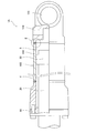
- FIG. 1 is a partial cross-sectional view of a hydraulic cylinder including a cylinder according to a first embodiment of the present invention.
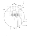
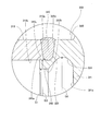
- FIG. 2 is an enlarged view of a portion II in FIG.
- FIG. 3 is a diagram showing a flow of force (force lines) transmitted from the cylinder bottom to the cylinder tube when the cylinder receives a tensile load, and corresponds to FIG.
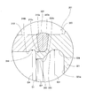
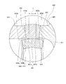
- FIG. 4 is an enlarged cross-sectional view of a cylinder according to a modification of the first embodiment of the present invention.
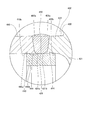
- FIG. 5 is an enlarged cross-sectional view of a cylinder according to another modification of the first embodiment of the present invention.
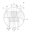
- FIG. 6 is an enlarged cross-sectional view of a cylinder according to another modification of the first embodiment of the present invention.
- FIG. 1 is a partial cross-sectional view of a hydraulic cylinder including a cylinder according to a first embodiment of the present invention.
- FIG. 2 is an enlarged view of a portion II in FIG.
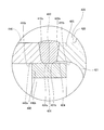
- FIG. 7 is an enlarged cross-sectional view of a cylinder according to another modification of the first embodiment of the present invention.
- FIG. 8 is an enlarged cross-sectional view of a cylinder according to the second embodiment of the present invention.
- FIG. 9 is an enlarged cross-sectional view of a cylinder according to a modification of the second embodiment of the present invention.
- FIG. 10 is an enlarged cross-sectional view of a cylinder according to another modification of the second embodiment of the present invention.
- FIG. 11 is an enlarged cross-sectional view of a cylinder according to another modification of the second embodiment of the present invention.
- FIG. 12 is an enlarged cross-sectional view of a cylinder according to the third embodiment of the present invention.
- FIG. 13 is an enlarged cross-sectional view of a cylinder according to a modification of the third embodiment of the present invention.
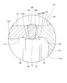
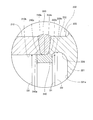
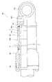
- FIG. 14 is a partial cross-sectional view of a hydraulic cylinder including a cylinder according to a fourth embodiment of the present invention.
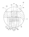
- FIG. 15 is an enlarged view of the XV portion in FIG.
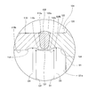
- FIG. 16 is a diagram for explaining deformation that occurs in the positioning portion when the cylinder receives a tensile load.
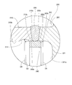
- FIG. 17 is an enlarged cross-sectional view of a cylinder according to a modification of the fourth embodiment of the present invention.
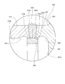
- FIG. 18 is an enlarged cross-sectional view of a cylinder according to another modification of the fourth embodiment of the present invention.
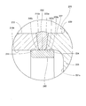
- FIG. 19 is an enlarged cross-sectional view of a cylinder according to another modification of the fourth embodiment of the present invention.
- FIG. 20 is an enlarged cross-sectional view of a cylinder according to another modification of the fourth embodiment of the present invention.
- FIG. 21 is an enlarged cross-sectional view of a cylinder according to another modification of the fourth embodiment of the present invention.
- FIG. 22 is an enlarged cross-sectional view of a cylinder according to another modification of the fourth embodiment of the present invention.
- the pressure resistant device stores fluid, and the pressure of the fluid acts on the pressure resistant device from the inside.
- the pressure-resistant device is the cylinder 100, 101, 102, 103, 104, 200, 201, 202, 203, 300, 301 used for the hydraulic cylinder (fluid pressure cylinder) 1A, and used for the hydraulic cylinder 1B.
- the cylinders 400, 401, 402, 403, 404, 405, and 406 will be described.
- the hydraulic cylinder 1 ⁇ / b> A includes a hollow cylinder 100, a piston rod 20 inserted into the cylinder 100, and slides along the inner peripheral surface of the cylinder 100 provided at the end of the piston rod 20. And a piston 30 that performs.
- the inside of the cylinder 100 is divided into a rod side chamber 4 and an anti-rod side chamber 5 by a piston 30.
- the rod side chamber 4 and the anti-rod side chamber 5 are filled with working oil as a working fluid.
- the hydraulic cylinder 1 ⁇ / b> A is extended by supplying hydraulic oil to the anti-rod side chamber 5 and discharging the hydraulic oil in the rod side chamber 4.
- the hydraulic cylinder 1 ⁇ / b> A is contracted by supplying hydraulic oil to the rod side chamber 4 and discharging hydraulic oil in the non-rod side chamber 5.
- the pressure of the hydraulic oil acts on the cylinder 100.
- the cylinder 100 includes a cylinder tube (cylindrical main body portion) 110 and a cylinder bottom (lid portion) 120 that closes one opening of the cylinder tube 110.
- the piston rod 20 extends from the cylinder 100 through the other opening of the cylinder tube 110.
- the other opening of the cylinder tube 110 is closed by a cylinder head 50 that slidably supports the piston rod 20.
- a direction along the central axis of the cylinder tube 110 is referred to as an “axial direction”, and a radial direction centered on the central axis of the cylinder tube 110 is referred to as a “radial direction” along the central axis of the cylinder tube 110.
- the direction is referred to as “circumferential direction”.
- FIG. 2 is an enlarged view of part II in FIG.
- the cylinder bottom 120 includes a bottom main body 121 that covers the opening of the cylinder tube 110, and an annular wall portion 122 that extends from the bottom main body 121 in the axial direction.
- the end surface 121a of the bottom main body 121 faces the non-rod side chamber 5 (see FIG. 1).
- the bottom main body 121 is provided with an attachment portion 123 (see FIG. 1) for attaching the hydraulic cylinder 1A to another device.
- the inner diameter D1 of the front end portion (end portion) 122a of the wall portion 122 is substantially equal to the inner diameter D2 of the open end portion (end portion) 110a of the cylinder tube 110.
- the front end portion 122a of the wall portion 122 is joined to the open end portion 110a of the cylinder tube 110 by welding.
- any method such as arc welding including plasma welding and TIG welding, gas welding, laser welding, electron beam welding, resistance welding, and friction welding can be used.
- the joint part 130 is formed by welding the opening end part 110a of the cylinder tube 110 and the front end part 122a of the wall part 122.
- the cylinder tube 110 and the cylinder bottom 120 are integrated via the joint 130 by welding the cylinder tube 110 and the wall 122.
- the joint 130 may protrude from the inner peripheral surface 110b of the cylinder tube 110 and the inner peripheral surface 122b of the wall 122.
- FIG. 2 shows a state in which a part of the joint portion 130 protrudes from the inner peripheral surface 110b of the cylinder tube 110 and the inner peripheral surface 122b of the wall portion 122, that is, a state in which the protrusion 131 is formed.
- the bases 110 c and 122 c of the protrusion 131 are formed in the vicinity of the inner periphery of the opening end portion 110 a of the cylinder tube 110 and in the vicinity of the inner periphery of the tip end portion 122 a of the wall portion 122.
- An annular groove (first groove) 124 extending in the circumferential direction is formed on the inner peripheral surface 122 b of the wall 122.
- the maximum inner diameter D3 (hereinafter referred to as “the inner diameter D3 of the groove portion 124”) in the groove portion 124 of the wall portion 122 is larger than the inner diameter D1 of the tip end portion 122a of the wall portion 122 and the inner diameter D2 of the opening end portion 110a of the cylinder tube 110. large.
- the groove portion 124 is formed on the entire circumference in the circumferential direction.
- the groove part 124 may be formed in a part in the circumferential direction.
- the cross section of the groove 124 is formed in an arcuate shape.
- the cross section of the groove portion 124 may have a shape other than an arc shape, for example, a triangular shape, a quadrangular shape, or the like.
- the cross section of the groove 124 is preferably arcuate, and in this case, stress concentration in the groove 124 can be reduced.
- FIG. 3 is a diagram showing a flow of force (force lines) transmitted from the cylinder bottom 120 to the cylinder tube 110 when the cylinder 100 receives a tensile load as an axial force, and corresponds to FIG.
- the flow of force is indicated by a broken line, and hatched lines indicating the cross sections of the cylinder tube 110, the cylinder bottom 120, and the joint 130 are omitted.
- the tensile load acts on the cylinder 100 by, for example, the pressure of the hydraulic oil in the cylinder 100 and a load connected to the hydraulic cylinder 1A.
- an annular groove portion 124 is formed on the inner peripheral surface 122 b of the wall portion 122. Therefore, when the cylinder 100 receives an axial force, the force acting on the cylinder bottom 120 is transmitted to the cylinder tube 110 mainly through a portion of the wall portion 122 that is positioned radially outward from the bottom surface of the groove portion 124. .
- the inner diameter D3 of the groove portion 124 is larger than the inner diameter D1 of the front end portion 122a of the wall portion 122, it is difficult for force to be transmitted to the inner periphery of the front end portion 122a of the wall portion 122. Stress concentration generated at the root 122c of the protrusion 131 can be alleviated, and damage to the joint 130 and the cylinder bottom 120 can be prevented. Therefore, the durability of the cylinder 100 can be improved.
- the inner diameter D3 of the groove portion 124 is larger than the inner diameter D2 of the opening end portion 110a of the cylinder tube 110, it is difficult for force to be transmitted to the inner periphery of the opening end portion 110a of the cylinder tube 110. Stress concentration generated at the base 110c of the protrusion 131 can be alleviated, and damage to the joint 130 and the cylinder tube 110 can be prevented. Therefore, the durability of the cylinder 100 can be improved.
- the pressure of the hydraulic oil in the anti-rod side chamber 5 acts on the bottom main body 121 of the cylinder bottom 120 in the axial direction. If the groove portion 124 is not formed on the inner peripheral surface 122b of the wall portion 122, a larger force acts on the inner periphery of the tip end portion 122a of the wall portion 122 than the inner periphery of the opening end portion 110a of the cylinder tube 110. To do. Stress tends to concentrate on the root 110c and the root 122c, and the cylinder bottom 120 is easily damaged.
- the groove portion 124 is formed on the inner peripheral surface 122b of the wall portion 122, while the groove portion is not formed on the inner peripheral surface 110b of the cylinder tube 110.
- the force is less likely to be transmitted to the inner periphery of the tip 122a of the wall 122.
- the stress concentration generated at the root 122c of the protrusion 131 can be more reliably mitigated, and the cylinder bottom 120 can be prevented from being damaged.
- the rigidity of the wall 122 is lowered by the groove 124 formed on the inner peripheral surface 122b of the wall 122, and the wall 122 is easily elastically deformed. Since the wall 122 is easily deformed in accordance with the deformation of the cylinder tube 110, stress concentration generated at the roots 110c and 122c of the protrusion 131 can be reduced.
- the groove portion 124 is formed across the inner peripheral surface 122 b of the wall portion 122 and the end surface 121 a of the bottom main body 121.
- the groove portion 124 forms a curved surface between the inner peripheral surface 122 b of the wall portion 122 and the end surface 121 a of the bottom main body 121.
- the radius of curvature of the groove portion 124 can be increased. Stress concentration can be relaxed.
- FIG. 4 is an enlarged cross-sectional view showing a cylinder 101 according to a modification of the first embodiment.
- a groove portion (first groove portion) 114 extending in the circumferential direction is formed on the inner peripheral surface 110 b of the cylinder tube 110.
- the groove 114 is formed on the entire circumference in the circumferential direction.
- the maximum inner diameter D4 (hereinafter referred to as “the inner diameter D4 of the groove 114”) in the groove 114 of the cylinder tube 110 is larger than the inner diameter D1 of the tip 122a of the wall 122 and the inner diameter D2 of the opening end 110a of the cylinder tube 110. large.
- the groove 114 is not limited to a form formed on the entire circumference, and may be formed on a part in the circumferential direction.
- the cross section of the groove 144 is formed in an arcuate shape.
- the cross section of the groove 114 may have a shape other than an arc shape, for example, a triangle, a quadrangle, or the like.
- the cross section of the groove 114 is preferably arcuate, and in this case, stress concentration in the groove 114 can be reduced.
- the cylinder 101 similarly to the cylinder 100, it is difficult for force to be transmitted to the inner periphery of the opening end portion 110 a of the cylinder tube 110 and the inner periphery of the tip portion 122 a of the wall portion 122. Stress concentration generated at the root 110c and the root 122c of the protrusion 131 can be alleviated, and damage to the cylinder tube 110, the cylinder bottom 120, and the joint 130 can be prevented. Therefore, the durability of the cylinder 101 can be improved.
- FIG. 5 is an enlarged cross-sectional view showing a cylinder 102 according to a modification of the first embodiment.
- a groove portion (first groove portion) 114 is formed on the inner peripheral surface 110 b of the cylinder tube 110, and a groove portion (first groove portion) 124 is formed on the inner peripheral surface 122 b of the wall portion 122.
- the rigidity of the wall portion 122 is reduced by the groove portion 124 formed in the inner peripheral surface 122b of the wall portion 122.
- the wall 122 is easily deformed according to the deformation of the cylinder tube 110, and the stress concentration generated at the roots 110c and 122c of the protrusion 131 can be reduced.
- the groove portion 124 is formed across the inner peripheral surface 122 b of the wall portion 122 and the end surface 121 a of the bottom main body 121. Similar to the cylinder 100, the radius of curvature of the groove 124 can be increased, and the stress concentration in the groove 124 can be reduced.
- FIG. 6 is a cross-sectional view of a cylinder 103 according to a modification of the first embodiment.
- the cylinder tube 110 includes a tube main body 111 that houses the piston 30 (see FIG. 1), and an annular portion 112 that extends annularly from one end of the tube main body 111 in the axial direction.
- the tip of the annular portion 112 is an opening end portion 110 a of the cylinder tube 110, and the opening of the cylinder tube 110 is formed by the tip of the annular portion 112.
- the inner diameter of the tube body 111 is substantially equal to the outer diameter of the piston 30, and the piston 30 can slide along the inner peripheral surface of the tube body 111.
- the inner diameter of the tube body 111 corresponds to a so-called cylinder diameter.
- the inner diameter of the annular portion 112 is larger than the inner diameter of the tube main body 111.
- the inner diameter of the wall 122 of the cylinder bottom 120 is larger than the inner diameter of the tube main body 111.
- the inner diameter D1 of the front end portion 122a of the wall portion 122 is substantially equal to the inner diameter of the opening end portion 110a of the annular portion 112 (the inner diameter D2 of the opening end portion 110a of the cylinder tube 110).
- the front end portion 122a of the wall portion 122 and the open end portion 110a of the annular portion 112 are joined by welding.
- the annular groove 114 is formed on the inner peripheral surface 110 b of the annular part 112.
- An inner diameter D4 of the groove portion 114 of the annular portion 112 is larger than an inner diameter D1 of the front end portion 122a of the wall portion 122 and an inner diameter D2 of the opening end portion 110a of the annular portion 112.
- the annular groove portion 124 is formed on the inner peripheral surface 122b of the wall portion 122 of the cylinder bottom 120.
- the inner diameter D3 of the groove portion 124 of the wall portion 122 is larger than the inner diameter D1 of the front end portion 122a of the wall portion 122 and the inner diameter D2 of the opening end portion 110a of the annular portion 112.
- the inner diameter D4 of the groove portion 114 and the inner diameter D3 of the groove portion 124 are larger than the inner diameter D1 of the distal end portion 122a of the wall portion 122 and the inner diameter D2 of the opening end portion 110a of the annular portion 112. It is difficult for force to be transmitted to the inner periphery of the portion 110 a and the inner periphery of the tip portion 122 a of the wall portion 122. Stress concentration generated at the root 110c and the root 122c of the protrusion 131 can be alleviated, and damage to the cylinder tube 110, the cylinder bottom 120, and the joint 130 can be prevented. Therefore, the durability of the cylinder 103 can be improved.
- the rigidity of the wall portion 122 is reduced by the groove portion 124 formed on the inner peripheral surface 122b of the wall portion 122. Therefore, the stress concentration generated at the roots 110c and 122c of the protrusion 131 can be reduced. it can.
- the cylinder 103 is not limited to the form in which the groove 114 and the groove 124 are formed on both the inner peripheral surface 110b of the annular portion 112 and the inner peripheral surface 122b of the wall portion 122.
- the groove 114 may be formed only on the inner peripheral surface 110 b of the annular portion 112, and the groove 124 may not be formed on the inner peripheral surface 122 b of the wall portion 122.
- the groove portion 124 may be formed only on the inner peripheral surface 122b of the wall portion 122, and the groove portion 114 may not be formed on the inner peripheral surface 110b of the annular portion 112.
- FIG. 7 is a cross-sectional view showing a cylinder 104 according to a modification of the first embodiment.
- a part of the inner peripheral surface 110b of the cylinder tube 110 and a part of the inner peripheral surface 122b of the wall portion 122 are deformed so as to protrude radially inward. That is, the protrusion 131 is formed by a part of the cylinder tube 110 and a part of the wall part 122.
- a groove portion 124 is formed on the inner peripheral surface 122b of the wall portion 122, and a groove portion 114 is formed on the inner peripheral surface 110b of the cylinder tube 110.
- the rigidity of the wall portion 122 is reduced by the groove portion 124 formed in the inner peripheral surface 122 b of the wall portion 122, so that stress concentration generated at the roots 110 c and 122 c of the protrusion 131 is reduced. can do. Since the groove portion 124 is formed across the inner peripheral surface 122b of the wall portion 122 and the end surface 121a of the bottom main body 121, similarly to the cylinder 100, the radius of curvature of the groove portion 124 can be increased, and the stress concentration of the groove portion 124 can be increased. Can be relaxed.
- the cylinder 104 is not limited to the form in which the groove 114 and the groove 124 are formed on both the inner peripheral surface 110b of the cylinder tube 110 and the inner peripheral surface 122b of the wall 122.
- the groove 114 may be formed only on the inner peripheral surface 110 b of the cylinder tube 110, and the groove 124 may not be formed on the inner peripheral surface 122 b of the wall portion 122.
- the groove 124 may be formed only on the inner peripheral surface 122b of the wall 122, and the groove 114 may not be formed on the inner peripheral surface 110b of the cylinder tube 110.
- cylinders 200, 201, 202, and 203 according to a second embodiment of the present invention will be described with reference to FIGS.
- the same components as those of the cylinder 100 according to the first embodiment are denoted by the same reference numerals, and the description thereof is omitted.
- the hydraulic cylinders to which the cylinders 200, 201, 202, 203 can be applied are substantially the same as the hydraulic cylinder 1A shown in FIG.
- the cylinder 200 includes a cylinder tube 210, a cylinder bottom 220, and an annular positioning portion 240 that determines a relative position between the cylinder tube 210 and the cylinder bottom 220.
- the cylinder bottom 220 has a bottom main body 221 and an annular wall portion 222.
- the annular positioning portion 240 is disposed along the inner peripheral surface 210 b of the cylinder tube 210 and the inner peripheral surface 222 b of the wall portion 222.
- the positioning portion 240 is formed separately from the cylinder tube 210 and the wall portion 222 before the cylinder tube 210 and the wall portion 222 are joined.
- the cylinder tube 210 and the wall portion 222 are fitted to the outer peripheral surface 240 a of the positioning portion 240, and the opening end portion 210 a of the cylinder tube 210 and the wall portion 222 are The tip portions 222a are abutted against each other.
- heat is applied to the cylinder tube 210 and the wall portion 222 to join the opening end portion 210a and the tip end portion 222a.
- the positioning part 240 is joined to the joining part 230.
- the cylinder tube 210 and the wall 222 can be welded in a state where the axis of the cylinder tube 210 and the axis of the wall 222 are aligned.
- any method such as arc welding including plasma welding and TIG welding, gas welding, laser welding, electron beam welding, resistance welding, and friction welding can be used.
- a part of the outer peripheral surface 240 a of the positioning part 240 is joined to the joint part 230, and the other part of the outer peripheral face 240 a is not joined to the joint part 230. That is, the other part of the outer peripheral surface 240 a of the positioning part 240 is close to the cylinder tube 210 and the wall part 222 without passing through the joint part 230.
- the whole outer peripheral surface 240a of the positioning part 240 may be joined to the joining part 230.
- the positioning portion 240 is composed of the inner peripheral surface 210b and the inner end surface 210b. This corresponds to a protrusion protruding from the peripheral surface 222b. In other words, the positioning portion 240 corresponds to the protrusion 131 (see FIG. 2) in the cylinder 100.
- Bases (bases) 210 c and 222 c of the positioning portion 240 are formed in the vicinity of the inner periphery of the opening end portion 210 a of the cylinder tube 210 and in the vicinity of the inner periphery of the tip end portion 222 a of the wall portion 222.
- An annular groove (first groove) 224 is formed on the inner peripheral surface 222 b of the wall 222. Therefore, when the cylinder 200 receives an axial force, the force acting on the cylinder bottom 220 is transmitted to the cylinder tube 210 mainly through a portion of the wall portion 222 that is positioned radially outward from the bottom surface of the groove portion 224. .
- the groove portion 124 may be formed on the entire circumference in the circumferential direction or may be formed on a part in the circumferential direction.
- the inner diameter D3 of the groove part 224 of the wall part 222 is larger than the inner diameter D1 of the tip part 222a of the wall part 222. It is difficult for force to be transmitted to the inner periphery of the front end portion 222a of the wall portion 222, stress concentration generated at the root 222c can be reduced, and damage to the cylinder bottom 220 and the joint portion 230 can be prevented. Therefore, the durability of the cylinder 200 can be improved.
- the inner diameter D3 of the groove 224 is larger than the inner diameter D2 of the open end 210a of the cylinder tube 210.
- a force is hardly transmitted to the inner periphery of the opening end portion 210a of the cylinder tube 210, stress concentration generated at the root 210c can be relaxed, and damage to the cylinder tube 210 and the joint portion 230 can be prevented. Therefore, the durability of the cylinder 200 can be improved.
- the groove part 224 is formed outside the region facing the positioning part 240 in the inner peripheral surface 222b of the wall part 222. Since the positioning portion 240 is in contact with the inner peripheral surface 210b of the cylinder tube 210 and the inner peripheral surface 222b of the wall portion 222 in a wider range, the cylinder tube 210 and the wall portion 222 are not easily displaced in the radial direction at the time of joining. Therefore, an unintended step portion can be prevented from being formed between the cylinder tube 210 and the wall portion 222, and the durability of the cylinder 200 can be improved.
- the groove portion 224 formed on the inner peripheral surface 222 b of the wall portion 222 reduces the rigidity of the wall portion 222, and the wall portion 222 is easily elastically deformed. . Since the wall portion 222 is easily deformed in accordance with the deformation of the cylinder tube 210, the stress concentration generated at the roots 210c and 222c of the joint portion 230 can be more reliably mitigated.
- the groove 224 is formed across the inner peripheral surface 222b of the wall 222 and the end surface 221a of the bottom body 221. That is, the groove portion 224 forms a curved surface between the inner peripheral surface 222 b of the wall portion 222 and the end surface 221 a of the bottom main body 221. Compared to the case where a curved surface is formed between the inner peripheral surface 222b of the wall portion 222 and the surface of the bottom main body 221 irrespective of the groove portion 224, the radius of curvature of the groove portion 224 can be increased. Stress concentration can be relaxed.
- FIG. 9 is an enlarged cross-sectional view showing a cylinder 201 according to a modification of the second embodiment.
- a groove portion (first groove portion) 214 extending in the circumferential direction is formed on the inner peripheral surface 210b of the cylinder tube 210.
- the groove 214 is formed on the entire circumference in the circumferential direction.
- the inner diameter D4 of the groove portion 214 of the cylinder tube 210 is larger than the inner diameter D1 of the tip end portion 222a of the wall portion 222 and the inner diameter D2 of the opening end portion 210a of the cylinder tube 210.
- the groove part 214 is not limited to the form formed in the entire circumference, and may be formed in a part in the circumferential direction.
- the cylinder 201 similarly to the cylinder 200, it is difficult for force to be transmitted to the inner periphery of the open end portion 210 a of the cylinder tube 210 and the inner periphery of the tip end portion 222 a of the wall portion 222. Stress concentration generated at the root 210c and the root 222c can be alleviated, and damage to the cylinder tube 210, the cylinder bottom 220, and the joint portion 230 can be prevented. Therefore, the durability of the cylinder 201 can be improved.
- the groove part 214 is formed outside the area facing the positioning part 240 in the inner peripheral surface 210b of the cylinder tube 210. Therefore, similarly to the cylinder 200, the cylinder tube 210 and the wall portion 222 are not easily displaced in the radial direction at the time of joining, and the durability of the cylinder 201 can be improved.
- FIG. 10 is an enlarged cross-sectional view showing a cylinder 202 according to a modification of the second embodiment.
- a groove portion 214 is formed on the inner peripheral surface 210 b of the cylinder tube 210
- a groove portion 224 is formed on the inner peripheral surface 222 b of the wall portion 222.
- a part of the groove part 214 is formed in a region of the inner peripheral surface 210b of the cylinder tube 210 facing the positioning part 240
- a part of the groove part 224 is formed on the positioning part 240 of the inner peripheral surface 222b of the wall part 222. It is formed in the opposing region.
- FIG. 11 is an enlarged cross-sectional view showing a cylinder 203 according to a modification of the second embodiment.
- the entire groove 214 is formed in a region of the inner peripheral surface 210 b of the cylinder tube 210 that faces the positioning portion 240.
- the entire groove portion 224 is formed in a region of the inner peripheral surface 222 b of the wall portion 222 that faces the positioning portion 240.
- the cylinder 202 and the cylinder 203 are not limited to the form in which the groove 214 and the groove 224 are formed on both the inner peripheral surface 210b of the cylinder tube 210 and the inner peripheral surface 222b of the wall 222.
- the groove 214 may be formed only on the inner peripheral surface 210b of the cylinder tube 210, and the groove 224 may not be formed on the inner peripheral surface 222b of the wall 222.
- the groove portion 224 may be formed only on the inner peripheral surface 222b of the wall portion 222, and the groove portion 114 may not be formed on the inner peripheral surface 210b of the cylinder tube 210.
- the rigidity of the wall portion 222 is lowered by the groove portion 124 formed in the inner peripheral surface 222 b of the wall portion 222.
- the wall 222 is easily deformed according to the deformation of the cylinder tube 210, and the stress concentration generated at the roots 210c and 222c can be reduced.
- the groove portion 224 is formed across the inner peripheral surface 222b of the wall portion 222 and the end surface 221a of the bottom body 221. Similar to the cylinder 200, the radius of curvature of the groove 224 can be increased, and the stress concentration in the groove 224 can be reduced.
- cylinders 300 and 301 according to a third embodiment of the present invention will be described with reference to FIGS.
- the same components as those of the cylinders 100 and 200 according to the first and second embodiments are denoted by the same reference numerals, and the description thereof is omitted.
- the hydraulic cylinders to which the cylinders 300 and 301 can be applied are substantially the same as the hydraulic cylinder 1A shown in FIG.
- the cylinder 300 includes a cylinder tube 310 and a cylinder bottom 320.
- the cylinder bottom 320 has a bottom main body 321 and an annular wall portion 322.
- the wall portion 322 includes a positioning portion 340 that determines a relative position between the cylinder tube 310 and the wall portion 322.
- the positioning portion 340 is disposed along the inner peripheral surface 310b of the cylinder tube 310.
- the positioning portion 340 is formed separately from the cylinder tube 310 before the cylinder tube 310 and the wall portion 322 are joined.
- the cylinder tube 310 is fitted to the outer peripheral surface 340a of the positioning portion 340, and the opening end portion 310a of the cylinder tube 310 and the tip end portion 322a of the wall portion 322 are connected to each other. Butt each other.
- heat is applied to the cylinder tube 310 and the wall portion 322 to join the opening end portion 310a and the tip end portion 322a.
- the positioning part 340 is joined to the joining part 330.
- the cylinder tube 310 and the wall part 322 can be prevented from being displaced.
- any method such as arc welding including plasma welding and TIG welding, gas welding, laser welding, electron beam welding, resistance welding, and friction welding can be used.
- the positioning part 340 is formed in the wall part 322, it is not necessary to match the position of the wall part 322 and the positioning part 340 at the time of joining. Therefore, the cylinder tube 310 and the wall 222 can be easily joined, and the cylinder 300 capable of improving durability can be easily manufactured.
- a part of the outer peripheral surface 340 a of the positioning unit 340 is joined to the joint 330, and the other part of the outer peripheral surface 340 a is not joined to the joint 330. That is, the other part of the outer peripheral surface 340 a of the positioning part 340 is close to the cylinder tube 310 without the joint part 330 interposed therebetween.
- the entire outer peripheral surface 340 a of the positioning part 340 may be joined to the joint part 330.
- the positioning portion 340 protrudes from the inner peripheral surface 310b. It corresponds to the protruding part. In other words, the positioning portion 340 corresponds to the protrusion 131 (see FIG. 2) in the cylinder 100.
- a root (base) 310 c of the positioning portion 340 is formed on the inner periphery of the opening end portion 310 a of the cylinder tube 310.
- An annular groove 324 is formed on the inner peripheral surface 322 b of the wall 322. Therefore, when the cylinder 300 receives an axial force, the force acting on the cylinder bottom 320 is transmitted to the cylinder tube 310 mainly through a portion of the wall portion 322 that is positioned radially outward from the bottom surface of the groove portion 324. .
- the groove 324 may be formed on the entire circumference in the circumferential direction or may be formed on a part in the circumferential direction.
- the inner diameter D3 of the groove portion 324 of the wall portion 322 is larger than the inner diameter D2 of the open end portion 310a of the cylinder tube 310.
- a force is hardly transmitted to the inner periphery of the opening end portion 310a of the cylinder tube 310, stress concentration generated at the root 310c can be reduced, and damage to the cylinder tube 310 and the joint portion 330 can be prevented. Therefore, the durability of the cylinder 300 can be improved.
- FIG. 13 is an enlarged cross-sectional view showing a cylinder 301 according to a modification of the third embodiment.
- a groove (first groove) 314 is formed on the inner peripheral surface 310 b of the cylinder tube 310
- a groove (first groove) 324 is formed on the inner peripheral surface 322 b of the wall 322.
- the groove portion 313 and the groove portion 324 may be formed on the entire circumference in the circumferential direction, or may be formed on a part in the circumferential direction.
- the inner diameter D4 of the groove 314 of the cylinder tube 310 is larger than the inner diameter D2 of the open end 310a of the cylinder tube 310. Force is less likely to be transmitted to the inner periphery of the opening end portion 310a of the cylinder tube 310, stress concentration generated at the root 310c of the joint portion 330 can be more reliably mitigated, and damage to the cylinder tube 310 and the joint portion 330 can be prevented. can do. Therefore, the durability of the cylinder 300 can be improved.
- the groove portion 314 is formed outside the region facing the positioning portion 340 on the inner peripheral surface 310b of the cylinder tube 310.
- the positioning portion 340 is in contact with the inner peripheral surface 310b of the cylinder tube 310 in a wider range, and the cylinder tube 310 is not easily displaced in the radial direction with respect to the wall portion 322 at the time of joining. Therefore, an unintended stepped portion can be prevented from being formed between the cylinder tube 310 and the wall portion 322, and the durability of the cylinder 301 can be improved.
- the cylinder 300 is not limited to the form in which the annular groove 324 is formed only on the inner peripheral surface 322b of the wall 322 (see FIG. 12). Further, the cylinder 300 is not limited to the form (FIG. 13) in which the groove portion 314 and the groove portion 324 are formed on both the inner peripheral surface 310 b of the cylinder tube 310 and the inner peripheral surface 322 b of the wall portion 322.
- the groove 314 may be formed only on the inner peripheral surface 310 b of the cylinder tube 310, and the groove 324 may not be formed on the inner peripheral surface 322 b of the wall 322.
- the groove portion 314 is formed outside the region facing the positioning portion 340 on the inner peripheral surface 310 b of the cylinder tube 310. At least a part of the groove portion 314 may be formed in a region of the inner peripheral surface 310 b of the cylinder tube 310 that faces the positioning portion 340.
- the rigidity of the wall portion 322 is reduced by the groove portion 324 formed in the inner peripheral surface 322b of the wall portion 322, and the wall portion 322 is elastically deformed. It becomes easy to do. Since the wall portion 322 is easily deformed in accordance with the deformation of the cylinder tube 310, the stress concentration generated at the root 310c of the joint portion 330 can be reduced.
- the groove portion 324 is formed across the inner peripheral surface 322b of the wall portion 322 and the end surface 321a of the bottom main body 321. That is, the groove portion 324 forms a curved surface between the inner peripheral surface 322 b of the wall portion 322 and the end surface 321 a of the bottom main body 321. Compared with the case where a curved surface is formed between the inner peripheral surface 322b of the wall portion 322 and the surface of the bottom main body 321 regardless of the groove portion 324, the radius of curvature of the groove portion 324 can be increased, Stress concentration can be relaxed.
- the wall portion 322 has the positioning portion 340, and the positioning portion 340 is disposed along the inner periphery of the inner peripheral surface 310b of the cylinder tube 310.
- the positioning portion 340 may be provided integrally with the cylinder tube 310 and disposed along the inner peripheral surface 322b of the wall portion 322.
- the hydraulic cylinder 1 ⁇ / b> B includes a hollow cylinder 400, a piston rod 20 inserted into the cylinder 400, and slides along the inner peripheral surface of the cylinder 400 provided at the end of the piston rod 20. And a piston 30 that performs.
- the inside of the cylinder 400 is partitioned by the piston 30 into a rod side chamber 4 and an anti-rod side chamber 5.
- the rod side chamber 4 and the anti-rod side chamber 5 are filled with working oil as a working fluid.
- the hydraulic cylinder 1 ⁇ / b> B is extended when hydraulic oil is supplied to the anti-rod side chamber 5 and the hydraulic oil in the rod side chamber 4 is discharged.
- the hydraulic cylinder 1 ⁇ / b> B is contracted by supplying hydraulic oil to the rod side chamber 4 and discharging hydraulic oil in the non-rod side chamber 5.
- the pressure of the hydraulic oil acts on the cylinder 400.
- the cylinder 400 has an annular shape that determines a relative position between a cylinder tube (cylindrical main body) 410, a cylinder bottom (lid) 420 that closes one opening of the cylinder tube 410, and the cylinder tube 410 and the cylinder bottom 420. Positioning part 440.
- the piston rod 20 extends from the cylinder 400 through the other opening of the cylinder tube 410.
- the other opening of the cylinder tube 410 is closed by a cylinder head 50 that slidably supports the piston rod 20.
- FIG. 15 is an enlarged view of the XV portion in FIG.
- the cylinder bottom 420 includes a bottom main body 421 that covers the opening of the cylinder tube 410, and an annular wall portion 422 that extends in the axial direction from the bottom main body 421.
- the bottom main body 421 is provided with an attachment portion 423 (see FIG. 14) for attaching the hydraulic cylinder 1B to another device.
- the front end 422a of the wall 422 is joined to the open end 410a of the cylinder tube 410 by welding.
- welding any method such as arc welding including plasma welding and TIG welding, gas welding, laser welding, electron beam welding, resistance welding, and friction welding can be used.
- the joint portion 430 is formed by welding the opening end portion 410 a of the cylinder tube 410 and the tip end portion 422 a of the wall portion 422. By welding the cylinder tube 410 and the wall portion 422, the cylinder tube 410 and the cylinder bottom 420 are integrated via the joint portion 430.
- the annular positioning portion 440 is disposed along the inner peripheral surface 410b of the cylinder tube 410 and the inner peripheral surface 422b of the wall portion 422.
- the positioning part 440 is formed separately from the cylinder tube 410 and the wall part 422 before the cylinder tube 410 and the wall part 422 are joined.
- the cylinder tube 410 and the wall portion 422 are fitted to the outer peripheral surface 440a of the positioning portion 440, and the opening end portion 410a and the wall portion 422 of the cylinder tube 410 are fitted.
- the tip portions 422a are abutted against each other.
- heat is applied to the cylinder tube 410 and the wall portion 422 to join the opening end portion 410a and the tip end portion 422a.
- the outer peripheral surface 440 a of the positioning portion 440 is joined to the joint portion 430.
- the cylinder tube 410 and the wall portion 422 can be prevented from being displaced.
- the cylinder tube 410 and the wall portion 422 can be welded in a state where the axis of the cylinder tube 410 and the wall portion 422 are aligned.
- the joint portion 430 is joined to only a part of the outer peripheral surface 440a of the positioning portion 440. That is, the joint surface 431 between the joint portion 430 and the positioning portion 440 is a part of the outer peripheral surface 440a of the positioning portion 440, and both edges 431a and 431b of the joint surface 431 in the axial direction are on the outer peripheral surface 440a of the positioning portion 440. Located in.
- An annular groove (first groove) 414 extending in the circumferential direction is formed on the inner peripheral surface 410b of the cylinder tube 410.
- An annular groove (second groove) 424 extending in the circumferential direction is formed on the inner peripheral surface 422b of the wall 422.
- the cross sections of the grooves 414 and 424 are formed in an arcuate shape.
- the groove part 414 and the groove part 424 may be formed on the entire circumference in the circumferential direction, or may be formed on a part in the circumferential direction.
- a part of the bottom surface of the groove portion 414 is formed by the joint portion 430. That is, the joint part 430 faces the groove part 414. Therefore, the position of one edge 431a of the joint surface 431 is determined by the groove 414.
- a part of the bottom surface of the groove portion 424 is formed by the joint portion 430. That is, the joint portion 430 faces the groove portion 424. Therefore, the position of the other edge 431 b of the joint surface 431 is determined by the groove portion 424.
- FIG. 16 is a view for explaining deformation that occurs in the positioning portion 440 when the cylinder 400 receives a tensile load as an axial force, and corresponds to FIG.
- the tensile load acts on the cylinder 400 by, for example, the pressure of hydraulic oil in the cylinder 400 and a load connected to the hydraulic cylinder 1B.
- a part of the outer peripheral surface 440 a of the positioning portion 440 is joined to the joint portion 430, and the inner peripheral surface 440 b of the positioning portion 440 is not joined to the joint portion 430.
- the positioning part 440 is curved so that the central part in the axial direction protrudes radially outward.
- the joint portion 430 receives a radial force from the positioning portion 440. Specifically, since the positioning portion 440 is deformed so that both end portions of the positioning portion 440 are separated from the cylinder tube 410 and the wall portion 422, a radially inward force is applied to both edges 431a and 431b of the joint surface 431. Works.
- the joint surface 431 expands in an axial direction, and the positioning part 440
- the outer peripheral surface 440a may be bonded to the bonding portion 430 beyond the intended range.
- the width (joining width) L of the joining surface 431 in the axial direction is increased, the positioning portion 440 is greatly deformed by the tensile load that the cylinder 400 receives.
- a larger radial inward force acts on both edges 431a and 431b of the joint surface 431. Due to the increase in the radial force, the stress at both edges 431a and 431b of the joint surface 431 increases, and the joint portion 430 is easily damaged. As a result, the durability of the cylinder 400 decreases.
- the joint portion 414 since the groove portion 414 is formed on the inner peripheral surface 410b of the cylinder tube 410 and the joint portion 430 faces the groove portion 414, the position of the edge 431a of the joint surface 431 is determined by the groove portion 414. Regardless of the welding conditions, the joint surface 431 does not expand toward the cylinder tube 410, and the amount of deformation of the positioning portion 440 does not increase. An increase in radial inward force acting on the edge 431a of the joint surface 431 can be prevented, and an increase in stress at the edge 431a of the joint surface 431 can be prevented. Therefore, the joint portion 430 can be prevented from being damaged, and the durability of the cylinder 400 can be improved.
- the groove part 424 is formed in the inner peripheral surface 422b of the wall part 422 and the joint part 430 faces the groove part 424, the position of the edge 431b of the joint surface 431 is determined by the groove part 424. Regardless of the welding conditions, the joint surface 431 does not expand toward the cylinder bottom 420, and the amount of deformation of the positioning portion 440 does not increase. Therefore, an increase in stress at the edge 431b of the joint surface 431 can be prevented, and the durability of the cylinder 400 can be improved.
- the groove portions 414 and 424 are provided on both sides of the joint portion 430 in the axial direction, the positions of both edges 431a and 431b of the joint surface 431 are determined by the groove portions 414 and 424. Regardless of the welding conditions, it is possible to more reliably prevent the joining surface 431 from expanding, and to prevent an increase in stress at the edges 431a and 431b of the joining surface 431. Therefore, the durability of the cylinder 400 can be improved.
- the inner diameter D41 of the tip (end) 422a of the wall 422 is substantially equal to the inner diameter D42 of the open end (end) 410a of the cylinder tube 410.
- the maximum inner diameter D43 (hereinafter referred to as “the inner diameter D43 of the groove part 424”) in the groove part 424 of the wall part 422 is larger than the inner diameter D41 of the tip part 422a of the wall part 422 and the inner diameter D42 of the opening end part 410a of the cylinder tube 410. large.
- the maximum inner diameter D44 in the groove portion 414 of the cylinder tube 410 (hereinafter referred to as “the inner diameter D44 of the groove portion 414”) is equal to the inner diameter D41 of the distal end portion 422a of the wall portion 422 and the inner diameter D42 of the opening end portion 410a of the cylinder tube 410. Bigger than.
- the joint portion 430 is joined to the positioning portion 440 and faces the groove portion 414 formed on the inner peripheral surface 410 b of the cylinder tube 410.
- the inner diameter D44 of the groove 414 of the cylinder tube 410 is larger than the inner diameter D45 of the edge 431a of the joint surface 431.
- the joint portion 430 is joined to the positioning portion 440 and faces the groove portion 424 formed on the inner peripheral surface 422b of the wall portion 422.
- the inner diameter D43 of the groove 424 of the wall 422 is larger than the inner diameter D46 of the edge 431b of the joint surface 431.
- the force acting on the cylinder tube 410 and the cylinder bottom 420 mainly passes through a portion of the joint portion 430 that is positioned radially outward from the bottom surfaces of the groove portions 414 and 424. It is transmitted to the bottom 420 and the cylinder tube 410. Since the inner diameters D44 and D43 of the groove portions 414 and 424 are larger than the inner diameters D45 and D46 of the edges 431a and 431b of the joint surface 431, it is difficult for force to be transmitted to the edges 431a and 431b of the joint surface 431. Stress concentration generated at the edges 431a and 431b of the joint surface 431 can be alleviated, and fatigue failure of the joint portion 430 due to repeated load can be prevented. Therefore, the durability of the cylinder 400 can be improved.
- the groove part 414 is formed in the area
- both ends of the positioning portion 440 in the axial direction are in contact with the cylinder tube 410 and the wall portion 422 during welding.
- the cylinder tube 410 and the wall portion 422 can be more reliably prevented from being displaced in the radial direction at the time of joining, and an unintended stepped portion can be prevented from being formed between the cylinder tube 410 and the wall portion 422. it can. Therefore, the durability of the cylinder 400 can be improved.
- FIG. 17 is an enlarged cross-sectional view showing a cylinder 401 according to a modification of the present embodiment.
- annular groove portions (second groove portions) 444 and 445 are formed on the outer peripheral surface 440 a of the positioning portion 440.
- the cross sections of the groove portions 444 and 445 are formed in an arcuate shape.
- the groove part 444 and the groove part 445 may be formed on the entire circumference in the circumferential direction, or may be formed on a part in the circumferential direction.
- the groove portion 444 is covered with the cylinder tube 410 and the joint portion 430. That is, the joint portion 430 faces the groove portion 444. Therefore, the position of one edge 431 a of the joint surface 431 is determined by the groove portion 444.
- the groove portion 445 is covered with the wall portion 422 and the joint portion 430. That is, the joint portion 430 faces the groove portion 445. Therefore, the position of the other edge 431 b of the joint surface 431 is determined by the groove portion 445.
- the joint surface 431 does not expand regardless of the welding conditions, and the deformation amount of the positioning portion 440 does not increase when the cylinder 401 receives a tensile load. Therefore, an increase in stress at the edges 431a and 431b of the joint surface 431 can be prevented, and the durability of the cylinder 401 can be improved.
- the groove portion 414 (see FIG. 15) is not formed on the inner peripheral surface 410b of the cylinder tube 410, and the groove portion 424 (see FIG. 15) is not formed on the inner peripheral surface 422b of the wall portion 422. Therefore, the wall thickness of the cylinder tube 410 and the wall part 422 can be made constant. Therefore, it is possible to prevent the cylinder tube 410 and the wall portion 422 from being destroyed by the cylinder 401 receiving a heavy load.
- FIG. 18 is an enlarged cross-sectional view showing a cylinder 402 according to another modification of the present embodiment.
- a groove portion (first groove portion) 424 is formed on the inner peripheral surface 422b of the wall portion 422, and a groove portion (second groove portion) 444 is formed on the outer peripheral surface 440a of the positioning portion 440.
- the positions of the edges 431a and 431b of the joint surface 431 are determined by the groove portions 424 and 444. Regardless of the welding conditions, the joint surface 431 does not expand, and the deformation amount of the positioning portion 440 does not increase when the cylinder 402 receives a tensile load. Therefore, an increase in stress at the edges 431a and 431b of the joint surface 431 can be prevented, and the durability of the cylinder 402 can be improved.
- the groove portion 414 (see FIG. 15) is not formed on the inner peripheral surface 410b of the cylinder tube 410. Therefore, the thickness of the cylinder tube 410 can be made constant. Therefore, it is possible to prevent the cylinder tube 410 from being broken due to the cylinder 402 receiving a large load.
- a groove 424 is formed on the inner peripheral surface 422b of the wall 422. Therefore, when the cylinder 402 receives an axial force, the force acting on the cylinder bottom 420 is transmitted to the cylinder tube 410 mainly through a portion of the wall portion 422 that is positioned radially outward from the bottom surface of the groove portion 424. .
- the pressure of the hydraulic oil in the non-rod side chamber 5 acts on the bottom main body 421 of the cylinder bottom 420 in the axial direction. If the groove portion 424 is not formed on the inner peripheral surface 422b of the wall portion 422, a larger force acts on the edge 431b of the joint surface 431 than the edge 431a of the joint surface 431, and the cylinder bottom 420 is easily damaged. .
- the groove portion 424 is formed on the inner peripheral surface 422b of the wall portion 422, while the groove portion 414 (see FIG. 15) is not formed on the inner peripheral surface 410b of the cylinder tube 410.
- the force is more difficult to be transmitted to the edge 431b of the joint surface 431.
- the stress concentration generated on the edge 431b of the joint surface 431 can be more reliably alleviated, and fatigue failure of the joint portion 430 due to repeated load can be prevented.
- FIG. 19 is an enlarged cross-sectional view showing a cylinder 403 according to another modification of the present embodiment.
- a groove portion (first groove portion) 414 is formed on the inner peripheral surface 410 b of the cylinder tube 410, and a groove portion (second groove portion) 445 is formed on the outer peripheral surface 440 a of the positioning portion 440.
- the positions of the edges 431a and 431b of the joint surface 431 are determined by the groove portions 414 and 445. Regardless of the welding conditions, the joint surface 431 does not expand, and the deformation amount of the positioning portion 440 does not increase when the cylinder 403 receives a tensile load. Therefore, an increase in stress at the edges 431a and 431b of the joint surface 431 can be prevented, and the durability of the cylinder 403 can be improved.
- the groove 424 (see FIG. 15) is not formed on the inner peripheral surface 422b of the wall 422. Therefore, the wall thickness of the wall portion 422 can be made constant. Therefore, it is possible to prevent the wall portion 422 from being broken due to the cylinder 403 receiving a large load.
- a groove 424 is formed on the inner peripheral surface 410b of the cylinder tube 410. Therefore, when the cylinder 403 receives an axial force, the force acting on the cylinder tube 410 is transmitted to the cylinder bottom 420 mainly through a portion of the cylinder tube 410 that is located radially outside the bottom surface of the groove 414. . It is difficult for force to be transmitted to the edges 431a and 431b of the joint surface 431, and stress concentration generated at the edges 431a and 431b of the joint surface 431 can be reduced. Therefore, fatigue failure of the joint portion 430 due to repeated loading can be prevented.
- FIG. 20 is an enlarged cross-sectional view showing a cylinder 404 according to another modification of the present embodiment.
- a groove (first groove) 424 is formed on the inner peripheral surface 422 b of the wall 422.
- Groove portions 414, 444, and 445 are not formed on the inner peripheral surface 410b of the cylinder tube 410 and the outer peripheral surface 440a of the positioning portion 440.
- the position of the edge 431b of the joint surface 431 is determined by the groove 424. Regardless of the welding conditions, the joint surface 431 does not expand toward the cylinder bottom 420, and the deformation amount of the positioning portion 440 does not increase when the cylinder 404 receives a tensile load. Therefore, an increase in stress at the edge 431b of the joint surface 431 can be prevented, and the durability of the cylinder 404 can be improved.
- the groove part 414 (refer FIG. 15) is not formed in the internal peripheral surface 410b of the cylinder tube 410, the thickness of the cylinder tube 410 can be made constant. Therefore, it is possible to prevent the cylinder tube 410 from being broken due to the cylinder 401 receiving a large load.
- the force acting on the cylinder bottom 420 mainly passes through a portion of the wall portion 422 that is positioned radially outward from the bottom surface of the groove portion 424. It is transmitted to the tube 410. It is difficult for force to be transmitted to the edges 431a and 431b of the joint surface 431, and stress concentration generated at the edges 431a and 431b of the joint surface 431 can be reduced. Therefore, fatigue failure of the joint portion 430 due to repeated loading can be prevented.
- the cylinder 404 is not limited to the form in which the groove portion 424 is formed on the inner peripheral surface 422b of the wall portion 422.
- the groove 414 may be formed only on the inner peripheral surface 410 b of the cylinder tube 410, and the groove 424 may not be formed on the inner peripheral surface 422 b of the wall 422.
- the positioning part 440 may be formed integrally with the cylinder bottom 420.
- FIG. 21 is an enlarged cross-sectional view showing a cylinder 405 according to another modification of the present embodiment.
- a groove (first groove) 424 is formed on the inner peripheral surface 422 b of the wall 422.
- a part of the groove portion 424 is formed outside the region of the inner peripheral surface 422b of the wall portion 422 that faces the positioning portion 440. That is, even when the cylinder 405 is not subjected to a tensile load, the groove 424 is not sealed by the outer peripheral surface 440a of the positioning portion 440.
- the position of the edge 431 b of the joint surface 431 is determined by the groove 424, as in the cylinder 404. Regardless of the welding conditions, the joint surface 431 does not expand toward the cylinder bottom 420, and the deformation amount of the positioning portion 440 does not increase when the cylinder 405 receives a tensile load. Therefore, an increase in stress at the edge 431b of the joint surface 431 can be prevented, and the durability of the cylinder 405 can be improved.
- the cylinder 405 receives an axial force, the force acting on the cylinder bottom 420 is not easily transmitted to the edges 431a and 431b of the joint surface 431, and the stress concentration generated at the edges 431a and 431b of the joint surface 431 is concentrated. Can be relaxed. Therefore, fatigue failure of the joint portion 430 due to repeated loading can be prevented.
- FIG. 22 is an enlarged cross-sectional view showing a cylinder 406 according to another modification of the present embodiment.
- groove portions (second groove portions) 444 and 445 are formed on the outer peripheral surface 440 a of the positioning portion 440.
- the cross sections of the groove portions 444 and 445 are formed in a triangular shape.
- the positions of the edges 431 a and 431 b of the joint surface 431 are determined by the groove portions 444 and 445 as in the cylinder 404. Regardless of the welding conditions, the joint surface 431 does not expand, and the deformation amount of the positioning portion 440 does not increase when the cylinder 406 receives a tensile load. Therefore, an increase in stress at the edges 431a and 431b of the joint surface 431 can be prevented, and the durability of the cylinder 406 can be improved.
- the cross-sectional shape of the groove portions 414 and 424 may be a triangle. Further, the cross-sectional shape of the groove portions 414, 424, 444, and 445 is not limited to an arcuate shape and a triangular shape, and may be other shapes such as a quadrangular shape and a pentagonal shape.
- the cylinders 100, 101, 102, 103, 104, 200, 201, 202, 203, 300, 301, 400, 402, 403, 404, and 405 include cylinder tubes 110, 210, 310, 410 and an annular wall 122.
- cylinder bottoms 120, 220, 320, 420 for closing the openings of the cylinder tubes 110, 210, 310, 410, and the cylinder tubes 110, 210, 310, 410 and the wall portions 122, 222, 322.
- At least one inner peripheral surface 110b, 21 of 422 b, 310b, 410b, 122b, 222b, 322b, 422b are formed with annular grooves 114, 214, 314, 414, 124, 224, 324, 424 extending in the circumferential direction, and the grooves 114, 214, 314 are formed.
- the inner diameters D3, D43, D4, and D44 of 414, 124, 224, 324, and 424 are the inner diameters D2 and D42 of the open end portions 110a, 210a, 310a, and 410a of the cylinder tubes 110, 210, 310, and 410, and the wall portions 122, It is larger than the inner diameters D1 and D41 of the tip portions 122a, 222a, 322a and 422a of 222, 322 and 422.
- the annular grooves 114, 214, 314, 414, 124, 224, 324, 424 are formed on the inner peripheral surfaces 110 b, 210 b, 310 b, 410 b of the cylinder tubes 110, 210, 310, 410 and the walls 122, 222,
- the inner diameters D3, D43, D4, and D44 of the annular grooves 114, 214, 314, 414, 124, 224, 324, and 424 formed on at least one of the inner peripheral surfaces 122b, 222b, 322b, and 422b of the cylinders 322 and 422 are cylinder tubes.
- the stress concentration generated at the roots 110c, 210c, 310c, 122c, 222c of the protrusion 131 can be alleviated, and the cylinders 100, 101, 102, 103, 104, 200, 201, 202, 203, 300, 301, 400, 402, 403, 404, 405 can be prevented from being damaged. Therefore, durability of the cylinders 100, 101, 102, 103, 104, 200, 201, 202, 203, 300, 301, 400, 402, 403, 404, and 405 can be enhanced.
- the groove portions 124, 224, 324, 424 are provided on the wall portions 122, 222, 322, 422. It is formed on the inner peripheral surfaces 122b, 222b, 322b, 422b.
- the grooves 124, 224, 324, and 424 are formed on the inner peripheral surfaces 122b, 222b, 322b, and 422b of the walls 122, 222, 322, and 422, so that the cylinders 100, 102, 103, 104, 200, 202, 203, 300, 301, 400, 402, 404, 405
- the axial force acting on the cylinder bottoms 120, 220, 320, 420 by the pressure of the hydraulic oil in the walls 122, 222, 322, 422 It is difficult to be transmitted to the inner periphery of the parts 122a, 222a, 322a, 422a.
- the protrusion 131 is formed in the vicinity of the inner periphery of the front end portions 122a, 222a, 322a, 422a of the wall portions 122, 222, 322, 422 by the joint portions 130, 230, 330, 430, the root 122c of the protrusion 131,
- the stress concentration generated in 222c can be more reliably alleviated, and the cylinders 100, 102, 103, 104, 200, 202, 203, 300, 301, 400, 402, 404, and 405 can be prevented from being damaged. Therefore, the durability of the cylinders 100, 102, 103, 104, 200, 202, 203, 300, 301, 400, 402, 404, 405 can be improved.
- the rigidity of the cylinder bottoms 120, 220, 320, and 420 is reduced by the grooves 124, 224, 324, and 424 formed in the inner peripheral surfaces 122b, 222b, 322b, and 422b of the walls 122, 222, 322, and 422.
- the cylinder bottoms 120, 220, 320, and 420 are easily elastically deformed.
- the stress concentration generated at the roots 110c, 122c, 210c, 222c, and 310c of the protrusion 131 can be more reliably mitigated.
- the cylinder tubes 110, 210, 310, and 410 can be easily formed. Can do.
- the groove portions 114, 214, 314, 414, 124, 224, 324, 424 are connected to the inner peripheral surface 110 b of the cylinder tubes 110, 210, 310, 410. , 210b, 310b, 410b and the inner peripheral surfaces 122b, 222b, 322b, 422b of the walls 122, 222, 322, 422.
- the grooves 114, 214, 314, 414, 124, 224, 324, 424 are connected to the inner peripheral surfaces 110 b, 210 b, 310 b, 410 b of the cylinder tubes 110, 210, 310, 410 and the walls 122, 222, 322, respectively.
- the axial force acting on the cylinder tubes 110, 210, 310, 410 and the cylinder bottoms 120, 220, 320, 420 is It is difficult to be transmitted by the inner periphery of the opening end portions 110a, 210a, 310a, 410a of the tubes 110, 210, 310, 410 and the inner periphery of the tip portions 122a, 222a, 322a, 422a of the wall portions 122, 222, 322, 422.
- the wall portion 322 has a positioning portion 340 that is disposed along the inner peripheral surface 310 b of the cylinder tube 310 and determines the relative position between the cylinder tube 310 and the wall portion 322.
- the cylinder tube 310 and the wall portion 322 are not easily displaced in the radial direction at the time of joining.
- An unintended stepped portion can be prevented from being formed between the cylinder tube 310 and the wall portion 322.
- a positioning part 340 is formed on the wall part 322. It is not necessary to match the positions of the wall portion 322 and the positioning portion 340 at the time of joining, and the cylinder tube 310 and the wall portion 322 can be easily joined. Therefore, the cylinders 300 and 301 capable of improving durability can be easily manufactured.
- the grooves 214, 314, 224, and 324 are positioned among the inner peripheral surfaces 210 b and 310 b of the cylinder tubes 210 and 310 and the inner peripheral surfaces 222 b and 322 b of the wall portions 222 and 322. It is formed outside the region facing the parts 240 and 340.
- the groove portions 214, 314, 224, and 324 are regions of the inner peripheral surfaces 210 b and 310 b of the cylinder tubes 210 and 310 and the inner peripheral surfaces 222 b and 322 b of the wall portions 222 and 322 that face the positioning portions 240 and 340. Since it is formed outside, the positioning portions 240 and 340 are in contact with the inner peripheral surfaces 210b and 310b of the cylinder tubes 210 and 310 and the inner peripheral surfaces 222b and 322b of the wall portions 222 and 322 in a wider range, and the cylinder tube 210 is joined at the time of joining. 310 and the walls 222 and 322 are less likely to be displaced in the radial direction. Therefore, an unintended stepped portion can be prevented from being formed between the cylinder tubes 210 and 310 and the wall portions 222 and 322, and the durability of the cylinders 200, 201, 300, and 301 can be improved. Can do.
- the present embodiment relates to hydraulic cylinders 1A and 1B that extend and contract when hydraulic oil is supplied to and discharged from the cylinder.
- the cylinders are cylinders 100, 101, 102, 103, 104, 200, 201, 202, 203, 300, 301, 400, 402, 403, 404, 405.
- the cylinder since the cylinder is the cylinder 100, 101, 102, 103, 104, 200, 201, 202, 203, 300, 301, 400, 402, 403, 404, 405, the cylinder has high durability. Have. Therefore, the durability of the hydraulic cylinders 1A and 1B can be improved.
- a part of the outer peripheral surface 440 a of the positioning portion 440 is joined to the joint portion 430 between the opening end portion 410 a of the cylinder tube 410 and the tip end portion 422 a of the wall portion 422.
- the joint portion 430 faces the groove portions 414 and 424.
- the joint portion 430 faces the groove portions 414 and 424 extending in the circumferential direction, the positions of the edges 431a and 431b of the joint surface 431 between the joint portion 430 and the positioning portion 440 are determined by the groove portions 414 and 424. Regardless of the welding conditions, the joining width L can be prevented from expanding, and an increase in stress at the joint 430 can be prevented. Therefore, durability of the cylinders 400, 402, 403, 404, and 405 can be improved.
- groove portions 444 and 445 extending in the circumferential direction are formed on the outer peripheral surface 440a of the positioning portion 440, and the joint portion 430 faces the groove portions 444 and 445.
- the joint portion 430 faces the groove portions 444 and 445, the positions of the edges 431a and 431b of the joint surface 431 between the joint portion 430 and the positioning portion 440 are determined by the groove portions 444 and 445. Regardless of the welding conditions, the joining width L can be prevented from expanding, and an increase in stress at the joint 430 can be prevented. Therefore, durability of the cylinders 402 and 403 can be improved.
- the groove portions 414, 424 are formed on both the inner peripheral surface 410b of the cylinder tube 410 and the inner peripheral surface 422b of the wall portion 422.
- the groove portion 414 is formed on the inner peripheral surface 410b of the cylinder tube 410 and the groove portion 424 is formed on the inner peripheral surface 422b of the wall portion 422, the axial force acting on the cylinder tube 410 and the cylinder bottom 420 is It is difficult to be transmitted to both edges 431a and 431b of the joint surface 431. Stress concentration generated on both edges 431a and 431b of the joint surface 431 can be alleviated, and fatigue failure of the joint portion 430 due to repeated load can be prevented. Therefore, the durability of the cylinder 400 can be improved.
- the groove portions 414, 424 are sealed by the outer peripheral surface 440a of the positioning portion 440.
- both ends of the positioning portion 440 in the axial direction are in contact with the cylinder tube 410 and the wall portion 422 during welding.
- the displacement of the cylinder tube 410 and the cylinder bottom 420 in the radial direction can be more reliably prevented, and an unintended stepped portion can be prevented from being formed between the cylinder tube 410 and the wall portion 422. Therefore, durability of the cylinders 402, 403, and 404 can be improved.
- the groove 424 is formed on the inner peripheral surface 422b of the wall 422, and the groove 444 is formed in a region of the outer peripheral surface 440a of the positioning portion 440 facing the inner peripheral surface 410b of the cylinder tube 410.
- the groove portion 424 is formed on the inner peripheral surface 422b of the wall portion 422, the axial force acting on the cylinder bottom 420 is transmitted to the edge 431b of the joint surface 431 between the joint portion 430 and the positioning portion 440. hard. Therefore, stress concentration generated at the edge 431b of the joint surface 431 can be relaxed, and fatigue failure of the joint portion 430 due to repeated load can be prevented.
- the groove part 444 is formed in the outer peripheral surface 440a of the positioning part 440, it is not necessary to form the groove part 414 in the inner peripheral surface 410b of the cylinder tube 410, and the thickness of the cylinder tube 410 can be made constant. Therefore, it is possible to prevent the cylinder tube 410 from being broken due to the cylinder 402 receiving a large load.
- the groove 414 is formed on the inner peripheral surface 410b of the cylinder tube 410, and the groove 445 is formed in a region of the outer peripheral surface 440a of the positioning portion 440 that faces the inner peripheral surface 422b of the wall 422.
- the groove portion 414 is formed on the inner peripheral surface 410b of the cylinder tube 410, the axial force acting on the cylinder tube 410 is transmitted to the edge 431a of the joint surface 431 between the joint portion 430 and the positioning portion 440. hard. Therefore, stress concentration generated at the edge 431a of the joint surface 431 can be relaxed, and fatigue failure of the joint portion 430 due to repeated load can be prevented.
- the groove part 445 is formed in the outer peripheral surface 440a of the positioning part 440, it is not necessary to form the groove part 424 in the inner peripheral surface 422b of the wall part 422, and the wall thickness of the wall part 422 can be made constant. Therefore, it is possible to prevent the wall portion 422 from being broken due to the cylinder 403 receiving a large load.
- the present embodiment relates to a hydraulic cylinder 1B that expands and contracts when hydraulic oil is supplied to and discharged from the cylinder.
- the cylinders are cylinders 400, 402, 403, 404, and 405.
- the cylinder since the cylinder is the above-described cylinder 400, 402, 403, 404, 405, the cylinder has high durability. Therefore, the durability of the hydraulic cylinder 1B can be improved.
- the cylinders 400, 401, 402, 403, 404, 405, and 406 have a cylindrical cylinder tube 410 and an annular wall portion 422, and an opening end portion 410 a of the cylinder tube 410 and the wall portion 422.
- the tip portion 422a is joined along the joint portion 430 to be disposed along the cylinder bottom 420 that closes the opening of the cylinder tube 410, the inner peripheral surface 410b of the cylinder tube 410, and the inner peripheral surface 422b of the wall portion 422.
- An annular positioning portion 440 that determines a relative position between the cylinder tube 410 and the cylinder bottom 420, and a part of the outer peripheral surface 440a of the positioning portion 440 is joined to the joint portion 430, and the inner peripheral surface 410b of the cylinder tube 410 , At least the inner peripheral surface 422b of the wall portion 422 and the outer peripheral surface 440a of the positioning portion 440. Thing, grooves 414,424,444,445 extending in the circumferential direction is formed, the junction 430, faces the groove 414,424,444,445.
- the joint portion 430 faces the groove portions 414, 424, 444, and 445 extending in the circumferential direction, the edge of the joint surface 431 between the joint portion 430 and the positioning portion 440 is formed by the groove portions 414, 424, 444, and 445.
- the positions of 431a and 431b are determined. Regardless of the welding conditions, the joining width L can be prevented from expanding, and an increase in stress at the joint 430 can be prevented. Therefore, the durability of the cylinders 400, 401, 402, 403, 404, 405, and 406 can be improved.
- the groove portions 414, 424, 444, 445 are provided on both sides of the joint portion 430 in the axial direction.
- both edges of the joint surface 431 between the joint portion 430 and the positioning portion 440 are formed by the two groove portions 414, 424, 444, and 445.
- the positions of 431a and 431b are determined. Regardless of the welding conditions, it is possible to more reliably prevent the joint width L from being increased, and to prevent an increase in stress at the joint portion 430. Therefore, the durability of the cylinders 400, 401, 402, 403, and 406 can be improved.
- the groove portions 444 and 445 are formed on the outer peripheral surface 440 a of the positioning portion 440.
- the groove portions 444 and 445 are formed on the outer peripheral surface 440 a of the positioning portion 440, it is not necessary to form the groove portions 414 and 424 in the cylinder tube 410 and the wall portion 422, and the wall of the cylinder tube 410 and the wall portion 422 is not required.
- the thickness can be made constant. Therefore, it is possible to prevent the cylinder tube 410 and the wall portion 422 from being destroyed due to the cylinders 401 and 406 receiving a heavy load.
- the cylinder used in the hydraulic cylinders 1A and 1B has been described as the pressure-resistant device.
- the pressure-resistant device is not limited to this, and may be a pressure vessel such as a cylinder for storing liquid or gas.
Landscapes
- Engineering & Computer Science (AREA)
- General Engineering & Computer Science (AREA)
- Mechanical Engineering (AREA)
- Physics & Mathematics (AREA)
- Fluid Mechanics (AREA)
- Chemical & Material Sciences (AREA)
- Combustion & Propulsion (AREA)
- Actuator (AREA)
Abstract
Un cylindre (100) est pourvu d'un tube (110) de cylindre et d'un fond (120) de cylindre qui ferme une ouverture du tube (110) de cylindre. Des parties (114, 124) à rainure annulaire s'étendant dans la direction circonférentielle sont formées sur des surfaces circonférentielles (110b, 122b) internes du tube (110) de cylindre et/ou une partie paroi (122) du fond (120) du cylindre. Les diamètres internes (D3, D4) des parties rainure (114, 124) sont supérieurs au diamètre interne (D2) d'une extrémité ouverte (110a) du tube (110) de cylindre et au diamètre interne (D1) d'une extrémité distale (122a) de la partie paroi (122).
Priority Applications (2)
| Application Number | Priority Date | Filing Date | Title |
|---|---|---|---|
| US16/093,710 US20190128291A1 (en) | 2016-04-18 | 2017-04-13 | Pressure resistant apparatus and fluid pressure cylinder |
| KR1020187029506A KR20180132692A (ko) | 2016-04-18 | 2017-04-13 | 내압 기기 및 유체압 실린더 |
Applications Claiming Priority (4)
| Application Number | Priority Date | Filing Date | Title |
|---|---|---|---|
| JP2016-083130 | 2016-04-18 | ||
| JP2016083129A JP2017194087A (ja) | 2016-04-18 | 2016-04-18 | 耐圧機器及び流体圧シリンダ |
| JP2016083130A JP6774210B2 (ja) | 2016-04-18 | 2016-04-18 | 耐圧機器及び流体圧シリンダ |
| JP2016-083129 | 2016-04-18 |
Publications (1)
| Publication Number | Publication Date |
|---|---|
| WO2017183561A1 true WO2017183561A1 (fr) | 2017-10-26 |
Family
ID=60116718
Family Applications (1)
| Application Number | Title | Priority Date | Filing Date |
|---|---|---|---|
| PCT/JP2017/015194 Ceased WO2017183561A1 (fr) | 2016-04-18 | 2017-04-13 | Équipement résistant à la pression et cylindre à pression hydraulique |
Country Status (3)
| Country | Link |
|---|---|
| US (1) | US20190128291A1 (fr) |
| KR (1) | KR20180132692A (fr) |
| WO (1) | WO2017183561A1 (fr) |
Cited By (1)
| Publication number | Priority date | Publication date | Assignee | Title |
|---|---|---|---|---|
| WO2019069797A1 (fr) * | 2017-10-05 | 2019-04-11 | Kyb株式会社 | Instrument de résistance à la pression et cylindre à pression de fluide |
Families Citing this family (1)
| Publication number | Priority date | Publication date | Assignee | Title |
|---|---|---|---|---|
| KR102923858B1 (ko) * | 2023-11-15 | 2026-02-05 | 디와이파워 주식회사 | 튜브의 용접부 구조가 개선된 유압 실린더 |
Citations (3)
| Publication number | Priority date | Publication date | Assignee | Title |
|---|---|---|---|---|
| JPS6075703U (ja) * | 1983-10-31 | 1985-05-27 | カヤバ工業株式会社 | 油圧シリンダ |
| JPH0866770A (ja) * | 1994-08-30 | 1996-03-12 | Nkk Corp | 固定管の片面突合せ溶接における初層溶接方法 |
| WO2014184291A2 (fr) * | 2013-05-16 | 2014-11-20 | Schwing Gmbh | Élément structural comprenant au moins deux parties soudées ensemble |
Family Cites Families (4)
| Publication number | Priority date | Publication date | Assignee | Title |
|---|---|---|---|---|
| US4324171A (en) * | 1978-06-16 | 1982-04-13 | Clark Equipment Company | Fluid device and method for making |
| US6964221B2 (en) * | 2001-12-21 | 2005-11-15 | Cnh America Llc | Welded hydraulic actuator including a seal and method of manufacturing same |
| CN102108989B (zh) * | 2010-07-23 | 2011-12-28 | 三一重工股份有限公司 | 一种液压油缸及液压缓冲系统、挖掘机和混凝土泵车 |
| JP5981877B2 (ja) * | 2013-04-26 | 2016-08-31 | 川崎重工業株式会社 | 液圧回転機が備えるピストン及び液圧回転機 |
-
2017
- 2017-04-13 WO PCT/JP2017/015194 patent/WO2017183561A1/fr not_active Ceased
- 2017-04-13 US US16/093,710 patent/US20190128291A1/en not_active Abandoned
- 2017-04-13 KR KR1020187029506A patent/KR20180132692A/ko not_active Withdrawn
Patent Citations (3)
| Publication number | Priority date | Publication date | Assignee | Title |
|---|---|---|---|---|
| JPS6075703U (ja) * | 1983-10-31 | 1985-05-27 | カヤバ工業株式会社 | 油圧シリンダ |
| JPH0866770A (ja) * | 1994-08-30 | 1996-03-12 | Nkk Corp | 固定管の片面突合せ溶接における初層溶接方法 |
| WO2014184291A2 (fr) * | 2013-05-16 | 2014-11-20 | Schwing Gmbh | Élément structural comprenant au moins deux parties soudées ensemble |
Cited By (2)
| Publication number | Priority date | Publication date | Assignee | Title |
|---|---|---|---|---|
| WO2019069797A1 (fr) * | 2017-10-05 | 2019-04-11 | Kyb株式会社 | Instrument de résistance à la pression et cylindre à pression de fluide |
| US11174881B2 (en) | 2017-10-05 | 2021-11-16 | Kyb Corporation | Pressure resistant device and fluid pressure cylinder |
Also Published As
| Publication number | Publication date |
|---|---|
| KR20180132692A (ko) | 2018-12-12 |
| US20190128291A1 (en) | 2019-05-02 |
Similar Documents
| Publication | Publication Date | Title |
|---|---|---|
| JP2017194087A (ja) | 耐圧機器及び流体圧シリンダ | |
| US5833245A (en) | Elastomer ring seal for pressurized fluids | |
| JP6611544B2 (ja) | 接合体、流体圧シリンダ、及び接合体の製造方法 | |
| WO2017183561A1 (fr) | Équipement résistant à la pression et cylindre à pression hydraulique | |
| JP6774210B2 (ja) | 耐圧機器及び流体圧シリンダ | |
| US11892055B2 (en) | Shock absorber | |
| JP6530800B2 (ja) | 耐圧機器及び流体圧シリンダ | |
| EP3214337A1 (fr) | Amortisseur | |
| ES2304708T3 (es) | Anillo cortante metalico. | |
| ES2336555T3 (es) | Union de tubo y manguito asegurada contra la traccion. | |
| JP2017115905A (ja) | センサ付き流体シリンダ | |
| JP6646489B2 (ja) | 多段式流体圧シリンダ | |
| CN114517819B (zh) | 单管阻尼器组件和用于其的液压回弹止动组件 | |
| ES2290276T3 (es) | Metodo para fabricar un elemento embridado y elemento embridado. | |
| CN106662281A (zh) | 一种强化金属波纹管状的密封装置 | |
| JP6675169B2 (ja) | 圧力容器の密封構造 | |
| JP6924122B2 (ja) | 耐圧機器、流体圧シリンダ、及び耐圧機器の製造方法 | |
| WO2016185982A1 (fr) | Vérin hydraulique | |
| US8814169B2 (en) | Brush seal front plate and assembly | |
| JP7530217B2 (ja) | 耐圧機器及び流体圧シリンダ | |
| CN107923420B (zh) | 流体压缸 | |
| WO2021182184A1 (fr) | Instrument résistant à la pression et cylindre à pression de fluide | |
| JP7222979B2 (ja) | 往復動型流体圧機器 | |
| JP7379133B2 (ja) | 密封装置及び密封構造 | |
| JP2020029940A (ja) | 油圧嵌め用ハブのシール機構 |
Legal Events
| Date | Code | Title | Description |
|---|---|---|---|
| ENP | Entry into the national phase |
Ref document number: 20187029506 Country of ref document: KR Kind code of ref document: A |
|
| NENP | Non-entry into the national phase |
Ref country code: DE |
|
| 121 | Ep: the epo has been informed by wipo that ep was designated in this application |
Ref document number: 17785900 Country of ref document: EP Kind code of ref document: A1 |
|
| 122 | Ep: pct application non-entry in european phase |
Ref document number: 17785900 Country of ref document: EP Kind code of ref document: A1 |