WO2017183636A1 - 吸着ドローン飛行体および該吸着ドローン飛行体を使用した作業方法 - Google Patents
吸着ドローン飛行体および該吸着ドローン飛行体を使用した作業方法 Download PDFInfo
- Publication number
- WO2017183636A1 WO2017183636A1 PCT/JP2017/015599 JP2017015599W WO2017183636A1 WO 2017183636 A1 WO2017183636 A1 WO 2017183636A1 JP 2017015599 W JP2017015599 W JP 2017015599W WO 2017183636 A1 WO2017183636 A1 WO 2017183636A1
- Authority
- WO
- WIPO (PCT)
- Prior art keywords
- suction
- adsorbed
- drone
- propeller
- adsorption
- Prior art date
- Legal status (The legal status is an assumption and is not a legal conclusion. Google has not performed a legal analysis and makes no representation as to the accuracy of the status listed.)
- Ceased
Links
Images






Classifications
-
- B—PERFORMING OPERATIONS; TRANSPORTING
- B62—LAND VEHICLES FOR TRAVELLING OTHERWISE THAN ON RAILS
- B62D—MOTOR VEHICLES; TRAILERS
- B62D57/00—Vehicles characterised by having other propulsion or other ground- engaging means than wheels or endless track, alone or in addition to wheels or endless track
- B62D57/04—Vehicles characterised by having other propulsion or other ground- engaging means than wheels or endless track, alone or in addition to wheels or endless track having other than ground-engaging propulsion means, e.g. having propellers
-
- B—PERFORMING OPERATIONS; TRANSPORTING
- B64—AIRCRAFT; AVIATION; COSMONAUTICS
- B64C—AEROPLANES; HELICOPTERS
- B64C25/00—Alighting gear
- B64C25/02—Undercarriages
- B64C25/04—Arrangement or disposition on aircraft
-
- B—PERFORMING OPERATIONS; TRANSPORTING
- B64—AIRCRAFT; AVIATION; COSMONAUTICS
- B64C—AEROPLANES; HELICOPTERS
- B64C25/00—Alighting gear
- B64C25/32—Alighting gear characterised by elements which contact the ground or similar surface
-
- B—PERFORMING OPERATIONS; TRANSPORTING
- B64—AIRCRAFT; AVIATION; COSMONAUTICS
- B64U—UNMANNED AERIAL VEHICLES [UAV]; EQUIPMENT THEREFOR
- B64U10/00—Type of UAV
- B64U10/10—Rotorcrafts
- B64U10/13—Flying platforms
- B64U10/14—Flying platforms with four distinct rotor axes, e.g. quadcopters
-
- B—PERFORMING OPERATIONS; TRANSPORTING
- B64—AIRCRAFT; AVIATION; COSMONAUTICS
- B64U—UNMANNED AERIAL VEHICLES [UAV]; EQUIPMENT THEREFOR
- B64U2101/00—UAVs specially adapted for particular uses or applications
- B64U2101/30—UAVs specially adapted for particular uses or applications for imaging, photography or videography
Definitions
- the present invention relates to a suction drone vehicle and a working method using the suction drone vehicle.
- unmanned drones are attracting attention as being suitable for inspection of high places and dangerous places, they are required to approach and stop for more detailed inspection and work.
- unmanned small vehicles called multicopters and drones have spread around the world, and since these drones can fly freely in the air, they can be used for overpasses, bridges, building walls, and tunnels. It is attracting attention that it can be used for inspection of high places such as the ceiling and dangerous places and various work.
- Static flight is a feature of drone aircraft, but there are also disturbances such as wind, so it is difficult to stop at any point in any space, and high-accuracy observations such as photographing a 0.1 mm concrete crack in a bridge are possible. Can not. In order to obtain a more stable standstill, it is said that a part of the aircraft is pressed against the bridge, etc., and a method of trying to stand still by “leaning” is used, but in addition to changes in the wind of the environment, the flying airflow generated by the drone itself There is also a turbulence in the wind that is reflected by the structure, making it difficult to stop.
- Patent Document 1 a sound inspection device is mounted on an unmanned small aircraft (multicopter).
- Japanese Patent Application Laid-Open No. H10-228667 discloses a vehicle that is equipped with a vacuum suction device on a flying object body and performs a predetermined operation by adsorbing the flying object to an object to be adsorbed (inspected object).
- the flying body (multi-copter) described in Patent Document 2 has a structure attached outside the rotation radius of the propeller, and this structure includes a vacuum suction device, cleaning work, repair work, or audiovisual inspection. Equipped with equipment to perform work, batteries for energy, work equipment, etc., so the weight balance of the flying object is poor and flight stability is insufficient, making it difficult to attract the flying object to a predetermined position There is a problem.
- the object to be adsorbed is a ceiling wall surface, the flying object is tilted more than the normal flight posture (horizontal flight), so that the flight becomes unstable or sufficient for uneven adsorbed surfaces. There is a problem that a sufficient attractive force cannot be obtained.
- Patent Document 2 a so-called ejector that injects compressed air as a method of creating a negative pressure for adsorption is provided, so that it can be mounted in addition to increasing the weight load by mounting an air cylinder or the like. There is a problem that there is a limit to the size of the cylinder and the adsorption duration (workable time) is shortened.
- the present invention has been made to solve at least one of the above-described problems, and while flying stability is ensured to fly to a predetermined position of the object to be adsorbed and adsorbed to the object to be adsorbed, a predetermined operation is performed. It is intended to realize a suction drone vehicle that can be used. Further, the present invention intends to realize a suction drone flying body that can perform a variety of operations while maintaining a stable suction stationary posture even on an adsorbed object with unevenness, and a work method using the suction drone flying body. .
- a flying machine main body having a propeller, a vacuum suction device that includes a suction portion and sucks on an object to be sucked, and a working portion that performs a predetermined operation when sucking on the suction portion.
- the center of gravity of the vacuum suction device is connected to the base where the suction unit is disposed, the suction unit and the working unit are disposed at positions away from the rotation trajectory of the propeller, and the suction unit is attracted to the target object.
- the propeller has a function of stopping the rotation of the propeller.
- the weight balance is improved by connecting the flying body main body and the vacuum suction device at the center of gravity of the both, so that the object is attracted by flying to a predetermined position of the object to be sucked in a stable posture.
- Various operations can be performed in a stationary and stable state by adsorbing to an object.
- the adsorbed object is, for example, an overhead or a bridge, a wall surface of a building, a ceiling wall surface of a tunnel, or the like.
- the vacuum suction device is attached to a tip end portion of a support column which stands vertically from the base portion with respect to a rotation plane of the propeller.
- the vacuum suction device can be arranged at a position above or below the aircraft body, it is possible to widen the range of the suction possible position and the workable place.
- the vacuum suction device adjusts the angle between the joint and the joint that slidably couples the suction portion from the horizontal direction to the vertical direction with respect to the rotation plane of the propeller. It is preferable to have an actuator.
- the posture of the suction portion is controlled by the angle adjustment actuator so as to face the suction surface of the object to be attracted, and can be attracted to, for example, a vertical wall surface or a ceiling wall surface. .
- the vacuum suction device includes a joint that slidably connects the suction portion in a direction perpendicular to a rotation plane of the propeller, and 180 in a circumferential direction of the suction portion. It is preferable to have a spring that supports the suction portion at a position separated by a distance.
- the suction drone flying body of the present invention includes a flying body having a propeller, a suction portion, a vacuum suction device that sucks the object to be sucked, and performs a predetermined operation when sucking to the sucked portion.
- a work unit, and the adsorbing unit is configured to adsorb to the object to be adsorbed while providing a gap with the object to be adsorbed, and when adsorbing and fixing to the object to be adsorbed, or the object to be adsorbed
- it has a function of stopping the rotation of the propeller when the adsorbing part adsorbs to the object to be adsorbed, and enables vibration reduction.
- the suction drone aircraft can perform various operations in the suction stable stationary state, or move while maintaining the suction stable posture.
- a suction drone flying body that can perform a predetermined operation while moving.
- various delicate operations such as an acoustic inspection and a visual inspection can be performed in a stationary and stable state.
- the vacuum suction device includes a suction fan, and generates a stronger negative pressure by the action of the flow velocity due to the negative pressure generated by the suction fan and the gap, and It is preferable that it is what adsorb
- Adsorption having a gap between the adsorbing part and the object to be adsorbed applies the venturi effect.
- the negative pressure between the adsorbing part and the object to be adsorbed is primarily due to the suction fan.
- a stronger negative pressure is generated by the flow rate (velocity of air flow) due to this negative pressure and the flow rate of the gap. Occurs.
- a strong suction force suction force
- the suction drone flying object can be stably stopped even on an object to be attracted with unevenness.
- a pressure sensor is disposed in a suction port portion communicating with the gap between the suction portion and the object to be sucked, and the suction fan is based on a measurement value of the pressure sensor. It is preferable to control the rotation speed.
- the suction force becomes stronger if the rotation speed of the suction fan is increased, and the suction force becomes weaker if the rotation speed is reduced.
- the suction force can be controlled.
- the working unit has an acoustic inspection device or a visual inspection device, is in a stationary and stable state obtained by being adsorbed to the object to be adsorbed, and It is preferable to perform an acoustic inspection or a visual inspection in a state where the rotation of the propeller is stopped.
- the acoustic inspection device is, for example, a hammering inspection device
- the visual inspection device is, for example, a microscope camera.
- the operation can be performed in a stationary and stable state obtained by adsorbing the object to be adsorbed. Furthermore, if the propeller is stopped in the suction state, generation of vibration and noise can be suppressed, and precise inspection information can be obtained. Further, if the propeller is stopped during the above work, energy-saving operation is possible.
- the adsorption unit adsorbs to the object to be adsorbed, if the propeller is stopped, generation of vibration and noise can be suppressed, and precise inspection information can be obtained.
- a working method using the suction drone flying body of the present invention includes a flying body having a propeller, a vacuum suction device for sucking an object to be sucked, and a working part for performing a predetermined work. Flying a body, adsorbing the vacuum suction device to the wall surface of the target structure, and then stopping the rotation of the propeller to reduce vibrations and causing the working unit to perform a predetermined operation .
- the suction drone flying object ⁇ Flying the suction drone flying object, attracting it to the wall of the target structure to make it a stable and stable posture, and then stopping the rotation of the propeller to reduce the vibration, and then inspecting the work section. If the working unit is a microscope camera, it is observed and photographed.
- the suction drone flying object is stationary and enables precise observation, which has been impossible in the past. For example, it is possible to detect a fine crack from a captured image.
- the stationary holding enables accurate and reliable removal of wasps and the like.
- FIGS. 1 to 11 are schematic diagrams showing the respective configurations. Further, since the point of the present invention resides in the suction device mounted on the suction drone flying vehicle that is a drone, in the following description, description of the flight control device, the transceiver, various power sources, etc. of the suction drone flying vehicle is omitted.
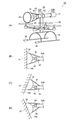
- FIG. 1A and 1B are diagrams showing a configuration of an adsorption drone flying body 1A according to a first example of the first embodiment, in which FIG. 1A is a perspective view, and FIG. 1B is a vacuum in a state of being adsorbed on an object to be adsorbed 100. It is a fragmentary sectional view showing adsorption device 11.
- the suction drone flying body 1 ⁇ / b> A includes a vacuum suction device 11, a flying body main body 13 having a vertical propeller 12, and a working unit 14.
- the vacuum suction device 11 includes a suction cylinder 15 and a suction section 16 that is airtightly connected to an end of the suction cylinder 15.
- the tail portion on the opposite side to the suction portion 16 of the suction cylinder 15 is an exhaust port portion 17.
- the adsorbing part 16 is an adsorbing plate, and an adsorbing airtight sponge rubber 18 is fixed to the periphery of the end face 16A on the adsorbed object 100 side of the adsorbing part 16 over the entire circumference.
- the planar shape of the suction portion 16 is a quadrangle, but is not limited to a quadrangle, and may be a circle or a polygon.
- the vacuum suction device 11 is provided with a suction passage 19 (including a suction port) that penetrates the suction portion 16, the suction cylinder 15 and the exhaust port portion 17, and a suction fan 20 is disposed in the suction passage 19. (See FIG. 1B).
- the vacuum suction device 11 includes a so-called decompression device.
- the flying body 13 includes four vertical propellers 12 arranged at the tip of a frame 26 extending radially from the base 25, and causes the suction drone flying body 1A to fly to a predetermined position of the object to be sucked 100. .
- Such an aircraft body 13 is generally called a drone or a multicopter, and the number of propellers 12 is not limited to four as shown, but may be one, three, five, or six.
- the shape of the propeller 12 is not limited to a vertical shape, and other shapes such as a shape extending obliquely upward may be adopted or mixed.
- a control unit having a function of rotating the propeller 12 and the suction fan 20 and stopping the rotation, and an operator and the control unit It is equipped with a communication interface that enables information communication and a battery or storage battery as an energy source.
- the vacuum suction device 11 is disposed substantially parallel to the rotation plane of each propeller 12 and is connected to the base portion 25 at the gravity center position G or in the vicinity of the gravity center position G.
- the suction unit 16 and the working unit 14 are arranged outside the rotation locus (rotation occupation area: represented by a two-dot chain line) in a plan view of the propeller 12, and on the outer side of the propeller 12 on the suction unit 16 side, a propeller guard 27, 27 is provided.
- the propeller guards 27 and 27 are attached to support bars respectively installed at both ends on the side surface side of the suction portion 16.
- the propeller guards 27 and 27 are provided so that the airframe tilts when the suction drone flying body 1A moves, and the propeller 12 does not contact or collide with the object to be adsorbed 100. Therefore, the propeller guards 27 and 27 may be arranged on all of the four propellers 12. Although illustration is omitted, a guard frame 35 (see FIG. 2A) may be attached below the vacuum suction device 11.
- the vacuum suction device 11 is provided with a suction passage 19 penetrating the inside of the exhaust port portion 17, the suction cylinder 15, and the suction portion 16.
- a suction pad 18 is provided on the end face 16A of the suction portion 16, and the suction pad 18 is surrounded by the end face 16A, the suction sponge rubber 18 and the object to be adsorbed 100 when closely contacting the object to be adsorbed 100.
- a chamber 21 is formed.
- a centrifugal fan, an axial fan or the like can be used as the suction fan 20.
- a suction fan having a strong suction force and a light weight is preferable.
- a ducted fan is preferable.
- the position of the suction fan 20 can be adjusted according to the type of fan selected. A heavy one may be arranged on the exhaust port 17 side, and if it is light, it may be arranged on the suction unit 16 side of the suction cylinder 15. A portion where the suction fan 20 is disposed may be referred to as a suction discharger.
- the working unit 14 includes, for example, an acoustic inspection device and a visual inspection device.
- FIG. 1A illustrates a hammering inspection apparatus as an example of an acoustic inspection apparatus.
- the hitting inspection device hits a wall surface with a hammer or the like, picks up the sound with a mylophone, and detects the presence or absence of an abnormality such as a crack from the change in the sound.
- a visual inspection device there is a camera (including a video camera), but when a fine abnormality is detected, a microscope camera or the like is equipped. In such an inspection device, for example, in order to accurately detect a fine crack of 0.1 mm or less, it is desirable that the suction drone flying body 1A is attracted to the object to be adsorbed 100 and inspected in a stationary stable state.
- an adsorbing sponge rubber 18 serving as an adsorbing surface of the adsorbing portion 16 that is an adsorbing plate is fixed so as to protrude out of the rotational occupation area of the four propellers 12.
- the suction drone flying body 1A can be horizontally moved in accordance with an object to be adsorbed such as a wall surface to be fixed, thereby being adsorbed and fixed.
- the following states are obtained by adsorption fixation. That is, it is possible to perform an inspection or the like with the working unit 14 after reducing vibration by stopping the stationary stable state and the propeller 12. If the working unit 14 is a hammering inspection device, a hammering inspection is performed. If the working unit 14 is a microscope camera, it is observed or photographed.
- the suction drone air vehicle 1A is stationary due to the suction fixation, so that it is possible to perform precise observation, which has been impossible in the past, and it is possible to detect fine cracks from changes in the captured image and sound.
- the stationary holding enables accurate and reliable removal of wasps and the like.
- FIG. 2A and 2B are diagrams showing the configuration of the suction drone flying vehicle 1B according to the second example of the first embodiment, in which FIG. 2A is a perspective view, and FIG. 2 is a partial cross-sectional view showing an adsorption device 30.
- FIG. The same constituent members as those in the first embodiment are denoted by the same reference numerals as those in FIG.
- the suction drone flying body 1 ⁇ / b> B includes a vacuum suction device 30 and the flying body main body 13.
- the flying body 13 has the same configuration as that of the first embodiment described above, but two struts 31 and 31 are fixed to the base 25 while passing through the base 25 up and down.
- the vacuum suction device 30 is fixed to the upper end portions of the columns 31, 31 so as to be substantially horizontal with respect to the rotation plane of the propeller 12 at a substantially central portion in the length direction.
- the vacuum suction device 30 is provided with a bowl-shaped suction portion 32 at one tip portion, and is connected to a suction cylinder 33.
- a suction path 19 is provided at the center of the bottom of the suction part 32.
- the adsorption part 32 has a function as a buffer material when colliding with the object to be adsorbed 100.
- a suction fan 20 (see FIG. 1B) is disposed in the suction path 19. Instead of the suction part 32, it is possible to provide the suction part 16 shown in the first embodiment (see FIG. 1).
- the suction cylinder 33 is divided into a suction cylinder 33A on the suction part 32 side and a suction cylinder 33B on the exhaust port part 17 side, and is connected by a joint 34.
- the joint 34 is supported by the support columns 31 and 31 so that the suction cylinder 33A can be reciprocally swung from the horizontal direction to the vertical direction as indicated by arrows in the drawing.
- the suction cylinder 33B does not swing.
- the joint 34 is provided with a well-known angle adjusting actuator or manipulator, and the suction portion 32 can be freely swung at a desired angle.
- the peristaltic angle is controlled by a command from a control unit (not shown).
- the adsorbing part 32 can be adsorbed by adjusting the angle so that the flying body 13 is substantially orthogonal to the inclined surface or ceiling wall surface of the object to be adsorbed 100 while maintaining the flight stable state.
- suction part 32 is arrange
- guard frame 35 The lower side ends of the support columns 31 are fixed to the guard frame 35.
- Guard parts 36 and 36 are provided at the tip (left side in the drawing) of the guard frame 35 on the suction part 32 side, and the guard part 36 is covered with the propeller 12 when the suction drone flying vehicle 1B moves. It is formed of a buffer material so that it does not come into contact with or collide with the adsorbate 100.
- the guard frame 35 is also a stand (skid) at the time of landing. Although illustration is omitted, the base portion 25 is provided with a working portion 14 as shown in FIG.
- the space formed when the end face of the adsorbing portion 32 is in close contact with the adsorbed surface of the adsorbed object 100 is an adsorbing chamber 37.
- the suction fan 20 (not shown) is driven, the air in the suction chamber 37 is sucked and becomes a negative pressure with respect to the atmospheric pressure, and the suction force is generated, so that the suction object 20 is sucked.
- the adsorbing part 32 can adsorb the object to be adsorbed 100 to an overhanging wall surface (indicated by a two-dot chain line in the figure). Even such an inclined surface or ceiling wall surface can be adsorbed in accordance with the inclination of the object to be adsorbed 100 by swinging the adsorbing part 32 with the joint 34.
- the following state can be obtained by adsorption fixation. That is, after the vibration is reduced by stopping the stationary stable state and the propeller 12 or the like, an inspection or the like is performed by arranging the working unit 14 of the first embodiment described above. If the working unit 14 is a hammering inspection device, a hammering inspection is performed. If the working unit 14 is a microscope camera, it is observed or photographed.
- the suction drone air vehicle 1B is stationary due to the suction fixation, so that it is possible to perform precise observation, which has been impossible in the past, and to detect fine cracks from the captured image. In addition, the stationary holding enables accurate and reliable removal of wasps and the like.
- FIGS. 3A and 3B are diagrams showing the configuration of the suction drone flying vehicle 1C according to the third example of the first embodiment.
- FIG. 3A is a perspective view, and FIGS. It is explanatory drawing which shows the adsorption
- FIG. Since the third embodiment is the same as the second embodiment described above except for the angle adjustment mechanism of the suction part 32, the difference will be mainly described. Further, the same components as those in FIG. 2 are denoted by the same reference numerals as those in FIG.
- the suction drone flying body 1 ⁇ / b> C includes a vacuum suction device 30 and a flying body main body 13.
- the vacuum suction device 30 is configured by connecting a suction part 32, a suction cylinder 33, and an exhaust port part 17 in series.
- the suction cylinder 33 is divided into a suction cylinder 33A on the suction portion 32 side and a suction cylinder 33B on the exhaust port portion 17 side with the joint 42 interposed therebetween, and the suction cylinder 33A is connected to the joint 43.
- the suction portion 32 is connected to the suction cylinder 33A by two springs 44 and 45 separated by 180 degrees in the circumferential direction, and is supported so that the pulling force of both is equal during flight.
- a suction passage 19 penetrates from the bottom of the suction portion 32 to the exhaust port portion 17, and a suction fan 20 (see FIG. 1) is disposed in the suction passage 19.
- the springs 44 and 45 are compression springs.
- FIG. 3 (B) shows a state in which the adsorbing part 32 is adsorbed to the adsorbed surface of the substantially vertical adsorbed object 100, and the springs 44 and 45 connect the adsorbing part 32 to the suction cylinder 33A with substantially the same pulling force. is doing. That is, the suction unit 32 at this time is a case where the suction drone flying vehicle 1C is sucked in a posture during horizontal flight.
- FIG. 3 (B) shows a state in which the adsorbing part 32 is adsorbed to the adsorbed surface of the substantially vertical adsorbed object 100, and the springs 44 and 45 connect the adsorbing part 32 to the suction cylinder 33A with substantially the same pulling force. is doing. That is, the suction unit 32 at this time is a case where the suction drone flying vehicle 1C is sucked in a posture during horizontal flight.
- FIG. 3C shows a state where the adsorbing portion 32 is adsorbed on the adsorbed surface of the adsorbed object 100 that is reversely inclined (overhang).
- the spring 44 is contracted and the spring 45 is extended, so that the adsorbing portion 32 adsorbs following the inclination of the surface to be adsorbed.
- FIG. 3D illustrates a state in which the adsorbing unit 32 is adsorbed on an adsorbed surface that is inclined to the opposite side to the adsorbed unit 100 illustrated in FIG.
- the compression spring 44 is extended and the compression spring 45 is contracted, the attracted portion 32 can be attracted following the inclination of the attracted surface.
- the suction drone flying body 1C when the suction drone flying body 1C is flying horizontally and the suction portion 32 is pressed against the object to be attracted 100, the suction drone flying object 1C can be attracted by changing the angle freely following the inclination of the surface to be attracted.
- the suction portion 32 returns to the state shown in FIG. 3B by the restoring force of the springs 44 and 45.
- the suction drone 1 ⁇ / b> A includes a flying body 13 having a propeller 12, a suction unit 16, and a vacuum suction device 11 that sucks the object to be sucked 100.
- a working portion 14 that performs a predetermined work when sucked by the sucking portion 16, and the center of gravity position G of the vacuum suction device 11 is connected to a base portion 25 on which the propeller 12 is disposed.
- the suction part 16 and the working part 14 are disposed at positions separated from each other, and have a function of stopping the rotation of the propeller 12 when the suction part 16 is attracted to the object to be attracted 100.
- the suction drone flying vehicle 1A has a good weight balance and a stable posture by connecting the flying vehicle body 13 and the vacuum suction device 11 near the center of gravity G of the object 100 (elevated bridge, bridge, building wall surface,
- the adsorbing portion 16 is adsorbed by flying to a predetermined position on the ceiling wall of the tunnel), and various operations such as acoustic inspection and visual inspection can be accurately performed in a stable and stationary state.
- the vibration is reduced by, for example, stopping the stationary stable state and the propeller 12 by suction and fixing, and then the inspection is performed by arranging the working unit 14 of the first embodiment described above. If the working unit 14 is a hammering inspection device, a hammering inspection is performed.
- the working unit 14 is a microscope camera, it is observed or photographed.
- the suction drone air vehicle 1A is stationary due to the suction fixation, so that it is possible to perform precise observation, which has been impossible in the past, and it is possible to detect fine cracks from changes in the captured image and sound.
- the stationary holding enables accurate and reliable removal of wasps and the like.
- the vacuum suction device 30 is formed of the support columns 31 and 31 that are erected vertically from the base 25 to the rotation plane of the propeller 12. Attached to the tip. If the lengths of the support columns 31, 31 are changed, the vacuum suction device 30 can be arranged at a position above or below the flying body 13, so that the range such as the suction possible position and the workable place is expanded. It becomes possible.
- the vacuum suction device 30 can swing the suction part 32 from the horizontal direction to the vertical direction with respect to the rotation plane of the propeller 12.
- An angle adjusting actuator and a manipulator (not shown) of the joint 34 to be connected and the suction portion 32 are provided.
- the posture of the suction unit 32 is controlled to an angle that faces the suction surface of the target object 100, It can be adsorbed to either a vertical wall surface or a ceiling wall surface.
- the vacuum suction device 30 connects the suction portion 32 so as to be swingable in a direction perpendicular to the rotation plane of the propeller 12. 43 and springs 44 and 45 that support the suction portion 32 at positions 180 degrees apart in the circumferential direction of the suction portion 32.
- the following state can be obtained by suction fixation. That is, after the vibration is reduced by stopping the stationary stable posture and the propeller 12 or the like, the working unit 14 performs an inspection or the like. If the working unit 14 is a hammering inspection device, a hammering inspection is performed. If the working unit 14 is a microscope camera, it is observed or photographed.
- the suction drone aircraft 1A, 1B, and 1C are stationary due to the suction fixation, so that it is possible to perform precise observation that has been impossible in the past, and it is possible to detect fine cracks from the captured image.
- the stationary holding enables accurate and reliable removal of wasps and the like.
- the second embodiment is a non-contact method using the so-called Venturi effect that has a gap 53 between the adsorbing portions 16 and 55 and the object to be adsorbed 100 and adsorbs to the first embodiment described above. It is characterized by mold adsorption.
- FIGS. 4A and 4B are diagrams showing the configuration of the suction drone flying vehicle 1D according to the first example of the second embodiment, in which FIG. 4A is a perspective view and FIG. It is sectional drawing which shows the adsorption
- the suction drone flying body 1D shown in FIG. 4A is different from the suction drone flying body 1A described in the first example of the first embodiment described above (see FIG. 1A).
- the configuration is different and the others are the same. Therefore, the same components as those in FIG.
- the end surface 16 ⁇ / b> A of the adsorption portion 16 is provided with a plurality (four in the drawing) of convex portions 52.
- FIG. 4A is a perspective view
- FIG. It is sectional drawing which shows the adsorption
- the suction drone flying body 1D shown in FIG. 4A is different from the suction drone flying body 1A described in the first example of the first embodiment described above (see FIG. 1A).
- the configuration
- the convex portion 52 protrudes so as to form a gap 53 between the object to be adsorbed 100 and the end surface 51 when adsorbing to the object to be adsorbed 100.
- the convex portion 52 is a hemispherical projection, a slipper, a caster, a ball roller, or the like, and serves as a load reducing means when the suction drone flying body 1D moves while being attracted.
- the convex portion 52 contacts the object to be adsorbed 100 to form a gap 53, and air is sucked from the gap 53 through the suction path 19.
- the cross-sectional area of the flow path constituted by the gap 53 is narrower than the cross-sectional area of the suction path 19.
- the outer side of the gap 53 is an external space, and the gap 53 corresponds to a portion where the flow path cross-sectional area is reduced in the venturi tube, and becomes a negative pressure with respect to the atmospheric pressure due to the venturi effect. That is, it is possible to obtain a high suction force by the negative pressure generated by the suction of the suction fan 20 and the negative pressure generated by the flow velocity and the gap 53 by the suction fan 20.
- the suction drone flying vehicle 1D can be maintained in a stable and stationary state, and a predetermined operation by the working unit 14 can be executed. Since the convex portion 52 serves as a load reducing means, the convex portion 52 can move along the object to be adsorbed 100 in the adsorption state, and can move in the adsorption stable state, or perform a predetermined operation in the working unit 14 while moving. It becomes possible.
- FIG. 5 is a partial cross-sectional view showing the configuration of the suction portion 55 according to the second example of the second embodiment.
- the second embodiment shown in FIG. 5 can be adapted to the suction drone aircraft 1A to 1C described in the first embodiment (see FIGS. 1 to 3), and the suction portion 55 is used for the suction described above. Since it is different from the structure of the part 16, it demonstrates centering on the adsorption
- the suction portion 55 has a substantially bowl shape in which the suction port portion 56 on the object to be adsorbed 100 side is wide open, and includes the suction fan 20 on the downstream side of the suction port portion 56. In the figure, solid arrows indicate the flow of air.
- a pressure sensor 57 is disposed in the suction port portion 56.
- FIG. 5 shows a case where the surface to be adsorbed 100 has irregularities.
- the gap 53 is generated between the tip of the suction port portion 56 and the object to be adsorbed 100.
- the cross-sectional area of the flow path formed by the gap 53 is narrower than the maximum flow path cross-sectional area of the suction port portion 56.
- the gap 53 corresponds to a portion where the flow path cross-sectional area is narrowed in the venturi tube, and the inside of the suction hole portion 56 becomes a negative pressure with respect to the atmospheric pressure due to the venturi effect. That is, a high suction force (adsorption force) can be obtained by the negative pressure generated by the suction of the suction fan 20 and the negative pressure generated by the flow velocity of the suction fan 20 and the action of the gap 53.
- a pressure sensor 57 is disposed in the suction port portion 56, and the suction flow rate is changed by controlling the rotation speed of the suction fan 20 by a control unit (not shown) based on the measurement value of the pressure sensor 57, and the suction force (adsorption force). ) Can be adjusted.
- a flow velocity sensor (not shown) is arranged instead of the pressure sensor 57 on the upstream side and the downstream side of the suction fan 20, and the rotational speed of the suction fan 20 is controlled based on the difference in the flow velocity between the upstream side and the downstream side. You may do it.
- a strong adsorption force can be obtained even if there is a gap 53 with respect to the adsorption surface where the object to be adsorbed 100 has irregularities and steps, so that the flying body 13 is maintained in a stable and stationary state.
- a predetermined operation by the unit 14 can be executed. Further, since it is not close-contact type adsorption, it can be moved along the object to be adsorbed 100 in the adsorbed state, and it can be moved in the adsorbed stable state or a predetermined work can be performed by the working unit 14 while moving. Become.
- FIG. 5 Although the shape of the adsorption
- the suction passage 19A closest to the suction fan 20 is used as a throttle section of the flow passage cross-sectional area of the Venturi tube, and the suction cross section is enlarged downstream from the throttle section.
- a path 19B may be provided. Also in the suction port portion 56, the suction path 19A, and the suction path 19B, a negative pressure due to the venturi effect can be generated. The air flow at this time is represented by a dotted arrow.
- the suction force (adsorption force) is further increased by the negative pressure generated by the suction fan 20 and the negative pressure due to the synergistic effect of the venturi effect by providing the gap 53 and the venturi effect by providing the suction paths 19A and 19B. ) Can be increased.
- FIG. 6 is a partial cross-sectional view showing the configuration of the suction portion 55 according to a third example of the second embodiment.
- the example shown in FIG. 6 is a modification of the suction portion 55 (see FIG. 5) described in the second example of the second embodiment described above. Therefore, the same portions as those in the second embodiment will be described with the same reference numerals as those in FIG.
- the suction fan 20 is disposed on the tip side of the suction port portion 56 on the adsorbed object 100 side.
- the rotation plane position of the propeller 54 of the suction fan 20 protrudes outward from the peripheral edge portion of the suction port portion 56, and when the suction portion 55 is sucked by the suction target object 100, the suction target object 100 and the suction fan 20.
- a gap 53 is formed by the rotation plane. That is, the gap 53 between the rotation plane of the suction fan 20 and the object to be adsorbed 100 corresponds to the throttle portion of the channel cross-sectional area in the venturi tube.
- a plurality of convex portions 59 project from the peripheral edge portion of the suction port portion 56 toward the object to be adsorbed 100 side. Three or four convex portions 59 are arranged at regular intervals in the circumferential direction of the peripheral edge portion of the suction port portion 56, and four or more convex portions 59 may be arranged between adjacent convex portions 59 and a part of the suction path. Become.
- the convex portion 59 has such a height that the suction fan 20 does not contact the object to be adsorbed 100 when the adsorbing part 55 comes closest to the object to be adsorbed 100.
- FIG. 6 shows a case where the surface to be adsorbed 100 has irregularities.
- the gap 53 is generated between the rotation plane of the suction fan 20 and the object to be adsorbed 100.
- the cross-sectional area of the flow path formed by the gap 53 is much smaller than the cross-sectional area of the flow path in the suction port portion 56.
- the gap 53 corresponds to a portion where the channel cross-sectional area is narrowed in the venturi tube, and becomes a negative pressure with respect to the atmospheric pressure due to the venturi effect.
- a high suction force can be obtained by the negative pressure generated by the suction of the suction fan 20 and the negative pressure generated by the flow velocity of the suction fan 20 and the action of the gap 53.
- the surface to be adsorbed 100 is a flat surface without unevenness (including a flat surface with very small unevenness)
- the convex portion 59 contacts the object to be adsorbed 100 and the concave portion between the adjacent convex portions 59 is formed.
- Suction (adsorption) is made possible by the negative pressure generated by the venturi effect as a suction path.
- a pressure sensor 57 is disposed in the suction path 19 immediately downstream of the suction fan 20.
- the suction force (adsorption force) can be controlled by changing the suction flow velocity by controlling the rotational speed of the suction fan 20 based on the measured value of the pressure sensor 57 by a control unit (not shown).
- the suction section 55 may use a suction path 19A closest to the suction fan 20 as a throttle section having a flow passage cross-sectional area of the venturi tube, and a suction path 19B having an enlarged flow path cross-section area downstream from the throttle section. Also in the suction port portion 56, the suction path 19A, and the suction path 19B, a negative pressure due to the venturi effect can be generated. The air flow at this time is represented by a dotted arrow. With such a configuration, the suction force (adsorption force) is reduced by the negative pressure due to the negative pressure by the suction fan 20 and the synergistic effect of the venturi effect by providing the gap 53 and the venturi effect by providing the suction paths 19A and 19B. It becomes possible to raise.
- the suction fan 20 is used as the suction means.
- the suction force can be increased. This will be described with reference to FIG.
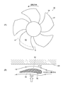
- FIG. 7A and 7B are diagrams showing an example of the propeller 54 constituting the suction fan 20 according to the first embodiment and the second embodiment.
- FIG. 7A is a plan view
- FIG. 7B is a diagram (A). It is sectional drawing cut
- the propeller 54 shown in FIG. 7A has five blades 61, but the number of blades and the planar shape are not particularly limited. It is assumed that the propeller 54 rotates counterclockwise.
- the cross-sectional shape of the blade 61 is such that the surface on the adsorbed object 100 side has a convex surface 62 that is thick on the front side of rotation and thin on the rear side of rotation.
- the back surface 63 on the opposite side is a flat surface.
- a solid line arrow represents the flow of air.
- the pressure is p1
- the flow velocity on the back surface 63 side is v2
- the pressure is p2, v1> v2, and p1 ⁇ p2 due to the Venturi effect. Therefore, this pressure difference acts as lift (indicated by a thick arrow) toward the adsorbent 100 side.
- the lift acts as a suction force in the suction portion 55. Therefore, the suction part 55 can obtain a strong suction force by the flow rate due to the negative pressure generated by the suction fan 20, the negative pressure generated by the action of the gap 53, and the lift of the propeller 54.
- the suction drone flying body 1D includes the flying body main body 13 having the propeller 12 and the suction unit 16, and the vacuum suction device 11 that sucks the object to be sucked 100. And a working unit 14 that performs a predetermined operation when adsorbing to the adsorbing unit 11, and the adsorbing unit 16 adsorbs to the object to be adsorbed 100 while providing a gap 53 between the adsorbing object 100.
- a predetermined operation is performed when adsorbing and fixing to the object to be adsorbed 100, or when moving while adsorbing to the object to be adsorbed 100, and when the adsorbing unit 16 adsorbs to the object to be adsorbed 100, the propeller 12 It has a function to stop rotation and enables vibration reduction.
- the suction drone flying vehicle 1D By adopting such a configuration, it is possible to make the suction drone flying vehicle 1D stable and stationary even if there are irregularities or steps on the surface to be attracted, and an acoustic inspection and visual inspection in a stable stationary state. It becomes possible to perform such work. Further, the adsorption of the adsorbing unit 16 to the object to be adsorbed 100 is a non-contact type adsorbing having a gap 53, so that the adsorbing part 16 moves along the object to be adsorbed 100 while being stationary or maintaining a stable posture. It is possible to realize the suction drone flying vehicle 1D capable of performing the above.
- the vacuum suction device 11 includes the suction fan 20, and a stronger negative pressure is generated by the action of the flow velocity and the gap 53 caused by the negative pressure generated by the suction fan 20, and Adsorb.
- the adsorption having the gap 53 between the adsorption unit 16 and the object to be adsorbed 100 applies the Venturi effect.
- the negative pressure between the adsorbing unit 6 and the object to be adsorbed 100 is primarily due to the suction fan 20, but a stronger negative pressure is generated by the flow rate and the gap 53 due to this negative pressure.
- a strong suction force (adsorption force) is generated, and it is possible to generate a strong suction force without being brought into close contact with the object to be adsorbed 100.
- the adsorption drone flying vehicle 1D can be adsorbed stably and stationary with respect to the object to be adsorbed 100 having irregularities and steps.
- a pressure sensor 57 is disposed in the suction port portion 56 communicating with the gap 53 between the adsorption portion 55 and the object to be adsorbed 100, and the pressure Based on the measured value of the sensor 57, the rotational speed of the suction fan 20 is controlled. In this way, even when the gap 53 between the object to be adsorbed 100 and the adsorbing portion 55 changes, the pressure (negative pressure level) is detected, and the rotational speed of the suction fan 20 is controlled, whereby the suction fan 20 is detected.
- the predetermined suction force can be maintained by increasing or decreasing the suction flow rate.
- the working unit 14 includes an acoustic inspection device or a visual inspection device.
- the stationary stable state obtained by adsorbing the object to be adsorbed 100 and the propeller 12 are stopped to perform the acoustic inspection or the visual inspection.
- other inspections such as an inspection using a high frequency and an inspection for analyzing a photographed image are possible.
- the suction drone flying body 1 ⁇ / b> A includes a vacuum suction device 11 that sucks the object to be attracted 100, a working unit 14 that performs a predetermined work, and a flying body that includes a propeller 12.
- the suction drone flying body 1A is caused to fly, and the vacuum suction device 11 is sucked onto the wall surface of the target structure (adsorbed object 100).
- the rotation of the propeller 12 is stopped to reduce the vibration, and the working unit 14 is caused to perform a predetermined work.
- the working unit 14 is a microscope camera, it is observed or photographed.
- the suction drone air vehicle 1A is stationary due to the suction fixation, so that it is possible to perform precise observation, which has been impossible in the past, and to detect fine cracks from the captured image.
- the working unit is a hammering inspection device, precise hammering inspection can be performed while reducing vibration and noise.
- the stationary holding enables accurate and reliable removal of wasps and the like.
- the propeller 12 it is possible to suppress the generation of vibration and noise and obtain more detailed inspection information.
- the propeller 12 is stopped during the above work, energy-saving operation is possible. If the rotation of the suction fan 20 of the vacuum suction device 11 is stopped after the operation is completed and the propeller 12 is rotated so that the number of rotations can fly, the suction drone flying vehicle 1A can be moved in flight. .
- FIG. 8 is a diagram showing an example of the suction drone according to the third embodiment
- FIG. 9 is a diagram showing an example of the suction moving drone according to the fourth embodiment
- FIG. 10 is an upper surface suction pad.
- FIG. 11 is a figure which shows the Example of the pad drone which a suction pad moves and absorbs an impact.
- the suction drone flying body according to each of the embodiments from FIG. 8 to FIG. 11 relates to visual inspection of a high place such as a tunnel ceiling and the back of a bridge, pest control for nesting in a high place, and the like.
- Unmanned drone aircraft are attracting attention as being suitable for inspection of high places and dangerous places, but they are required to approach and stop for more detailed inspection and work.
- Static flight is a feature of drone aircraft, but there are also disturbances such as wind, so it is difficult to stop at a single point in any space, and it is highly accurate, such as photographing a 0.1-mm concrete crack in a bridge stationary. Cannot be observed.
- Turbulent flow generated by the natural wind on the target structure when the drone is approaching, and flow disturbance such as blow-back generated when the flying levitation airflow generated by the drone hits the structure makes it difficult to approach and stop. . It is important to avoid the possibility of accidents such as collisions and crashes due to unforeseen airflow turbulence and the loss of control of the aircraft. It is also important to obtain stable stillness for obtaining detailed images such as microscopic observation. Furthermore, it is also important to reduce the area where insecticides are used to the minimum necessary, and to realize environmentally sound control.
- the vacuum suction device is mounted on the drone flying body, and the drone is sucked and fixed to the wall surface of the target structure.
- This suction fixation makes the drone stand still and enables precise observation, which was impossible in the past, and can detect fine cracks from the photographed image. With the stationary holding, accurate and reliable removal can be performed.
- the risk of falling and falling accidents can be suppressed, and traffic lights, traffic lights, and traffic lights can be checked without traffic restrictions.
- FIG. 8 shows the third embodiment, and FIG. Of the embodiment.
- the reference numerals in FIGS. 8 and 9 are the same. Since the point lies in the suction device mounted on the drone body (aircraft body), the flight control device, the transceiver, each power source, etc. of the suction drone aircraft are omitted.
- the adsorbing sponge rubber 103 serving as the adsorbing surface of the adsorbing plate 102 is fixed to the frame 110 so as to protrude out of the rotational occupation area of the four propellers 107.
- the drone is horizontally moved according to the wall surface to be fixed, thereby being fixed by suction.
- the propeller guard 109 prevents the propeller 107 from coming into contact with the wall surface due to the inclination of the fuselage when horizontally moving and performing suction.
- the hammering test is performed by the hammering test apparatus 111 after reducing vibration by stopping the stationary stable posture and propeller obtained by suction fixation. The same applies to observation with a microscope camera or the like.
- FIG. 9 shows a fourth embodiment in which a suction surface of the suction plate is flat and a slipper 112 that can slide on the wall surface is attached. It is possible to move while adjusting the suction force and adsorbing to the wall surface. Instead of the slipper 112, casters, ball rollers, or drive wheels can be attached. Both maintain a proper gap with the wall.
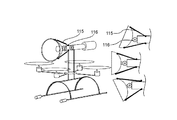
- FIG. 10 shows a position where the suction pad 113 is attached to the rotatable joint 114 and fixed to the upper side surface of the aircraft in the embodiment of the present invention.
- the suction pad is fixed to the lower surface of the structure for observing the drone, the suction pad 113 is rotated upward.
- FIG. 11 shows that the suction pad 113 is moved in a vertical and horizontal manner by a universal joint positioned by a spring and swings, and when the suction pad hits the suction surface, it follows and absorbs an impact. Show.
- FIGS. 8 to 11 enable a hammering inspection that requires the measurement support portion to be stationary without vibration and peristalsis.
- FIGS. 8 to 11 The configuration of the form shown in FIGS. 8 to 11 is as follows. That is, it is a drone type flying body in which a vacuum suction device in which a suction plate is hermetically connected to the other end of the suction cylinder connected to the suction / discharger is mounted.
- the suction / discharger of the flying object is equipped with a suction device including a centrifugal fan such as a turbo fan or a sirocco fan.
- this air vehicle suction / discharger is equipped with a suction device comprising an axial fan such as a propeller and a duct fan.
- a suction drone in which the suction exhauster of the flying object is equipped with an adsorption device consisting of a centrifugal fan such as a turbo fan or sirocco fan, or an adsorption device consisting of an axial flow fan such as a propeller or duct fan
- the suction surface of the suction plate is provided with irregularities so that an air flow is secured between the wall surface and the suction plate even in the suction state so as to be sucked by the venturi effect.
- the suction cylinder 105 is flexible and the suction plate is mounted with a suction device that can swing and extend, or the suction plate is movable in the vertical and horizontal directions with respect to the suction surface, and follows the suction surface for impact. Or a suction plate equipped with an angle adjusting actuator and can be freely positioned by a manipulator.
- suction plate with casters and slippers to move the wall surface while the suction drone aircraft is adsorbed, or a part of the flight propulsion force or levitation force by the exhaust of the suction discharger, or It is supposed to be used for all.
- the vacuum suction device described in each embodiment described above is mounted on the suction drone flying vehicle, but can be mounted on other than the suction drone flying vehicle. Although the illustration of the vacuum suction device alone is omitted, FIGS. This will be described with reference to FIG.
- the vacuum suction device includes the suction portion 16 or the suction portion 55 that sucks the object to be adsorbed while having the gap 53 between the object to be adsorbed 100, the flow rate due to the negative pressure generated by the suction fan 20, and the action of the gap 53. Thus, a stronger negative pressure is generated and adsorbed on the object to be adsorbed.
- the vacuum suction device having such a configuration applies the Venturi effect.
- the negative pressure generated in the suction unit 16 or the suction unit 55 is primarily due to the suction fan 20, but a stronger negative pressure is generated by the flow rate due to the negative pressure and the action of the gap 53.
- a strong suction force (adsorption force) is generated, which makes it possible to maintain a stationary and stable posture by adsorbing to the object to be adsorbed with unevenness and steps, and to move along the object to be adsorbed Is possible. Therefore, if the vacuum suction device is mounted on a device that performs work on vertical or inclined wall surfaces, ceiling wall surfaces, and dangerous places, various operations can be performed in a stable and stationary state.
- the present invention is not limited to the above-described embodiment, but includes modifications and improvements as long as the object of the present invention can be achieved.
- the vacuum suction devices 11 and 30 extend linearly, but if the exhaust port portion 17 is directed downward, the exhaust is lifted. It becomes possible to make it auxiliary.
- the vacuum suction devices 11 and 30 are rotatably connected to the flying body 13, the speed is increased or braked by exhausting from the exhaust port 17 in accordance with the traveling direction of the suction drone flying body. Is possible.
- each suction drone flying object of the second embodiment flies up to the object to be adsorbed 100 and works by adsorbing to the object to be adsorbed 100. It is also possible to carry out the work after flying to the object to be adsorbed and move it by the drive wheel, or to work while moving, and to collect it by flying after the work is completed. Further, when the work is performed while adsorbing to the object to be adsorbed 100, the propeller 12 is stopped, but the propeller 12 may not be stopped. If the propeller 12 is not stopped, it may be reduced by reducing the number of revolutions of the propeller 12 in order to reduce sound and vibration.
- Suction port part 57 ... Pressure sensor, 100 ... Object to be adsorbed, 102 ... Adsorption plate, 104 DESCRIPTION OF SYMBOLS ... Suction port, 105 ... Suction cylinder, 106 ... Exhaust port, 108 ... Motor, 110 ... Frame, 111 ... Sound-inspecting device, 112 ... Slipper, 113 ... Suction pad, 114 ... Rotatable joint, 116 ... U Versal fittings, G ... position of the center of gravity
Landscapes
- Engineering & Computer Science (AREA)
- Mechanical Engineering (AREA)
- Aviation & Aerospace Engineering (AREA)
- Remote Sensing (AREA)
- Chemical & Material Sciences (AREA)
- Combustion & Propulsion (AREA)
- Transportation (AREA)
- Manipulator (AREA)
Abstract
プロペラ12を有する飛行体本体13と、真空吸着装置11とを有し、真空吸着装置11は、被吸着物100との間に隙間53を設けつつ、被吸着物100に吸着する吸着部16を有し、被吸着物100に吸着固定する際、または被吸着物100に吸着しながら移動する際に、所定の作業を行う作業部14を有する吸着ドローン飛行体1D。吸引ファン20によって発生した負圧による流速と隙間53の作用により、さらに強い負圧を発生させて被吸着物100に吸着する。吸着部16が被吸着物100に吸着した際、プロペラ12を停止させ、静止状態で作業を行う吸着ドローン飛行体および作業方法である。 飛行の安定性を確保しつつ被吸着物の所望位置まで飛行させて被吸着物に吸着し、所定の作業を行える吸着ドローン飛行体および該飛行体を使用した作業方法を提供できる。
Description
本発明は、吸着ドローン飛行体および該吸着ドローン飛行体を使用した作業方法に関する。
老朽化する社会インフラの点検が急務となっている。また、スズメバチに代表される有害生物の駆除も、必要とされている。換言すれば、世界的に、老朽化した社会インフラ(インフラストラクチャー)の点検やメンテナンスが急務となってきている。また、スズメバチなどの有害生物の駆除なども問題になっている。
また、無人のドローン飛行体は、高所、危険個所点検に適していると注目されているが、より詳細な点検、作業をするために接近、静止することが求められている。近年、マルチコプターやドローンと称される無人小型飛行体が世界的に広がり、これらドローン飛行体は、空中を自在に飛行させることが可能であることから、高架や橋梁、ビルの壁面、トンネルの天井などの高所や危険個所の点検や各種作業などに活用可能性があると注目されている。
静止飛行は、ドローン飛行体の特徴であるが、風などの外乱もあり、任意の空間の1点で静止することは困難で、橋梁の0.1ミリのコンクリートひび割れを撮影するなど高い精度の観測ができない。より安定な静止を得るために機体の一部を橋梁などに押し付ける、「もたれかかり」による静止を試みる方法もとられているが、環境の風の変化に加え、ドローン自身の発生する浮揚飛翔気流が構造体に反射して生ずる風の乱れもあり、静止は困難である。
特許文献1には、無人小型飛行体(マルチコプター)に打音検査装置が搭載されている。また、特許文献2には、飛行体本体に真空吸着装置を装備し、被吸着物(被点検対象)に飛行体を吸着させて所定の作業を行うものが開示されている。
特許文献1に記載の打音検査装置が搭載された無人小型飛行体(マルチコプター)においては、打音検査をする際に、飛行体本体を索材によって構造物に懸架し、飛行体本体によって打音部を構造物に押し付けて打音検査を行うものである。しかし、飛行体本体を安定的に静止させることはできないので検査姿勢が安定せず、打音にばらつきが発生することから正確な打音検査を行えないという課題がある。
特許文献2に記載の飛行体(マルチコプター)には、プロペラの回転半径外に構造体が取り付けられており、この構造体には真空吸着装置をはじめ、清掃作業、修繕作業または視聴覚的な検査作業を行う器具、あるいはエネルギー源となる電池や作業用器具などが装備されることから、飛行体の重量バランスが悪く飛行の安定性が不十分で、所定位置に飛行体を吸着させることが難しいという課題がある。さらに、被吸着物が天井壁面のような場合には、飛行体が通常の飛行姿勢(水平飛行)よりも大きく傾くため飛行が不安定になることや、凹凸のある被吸着面に対して十分な吸着力が得られないという課題がある。さらに、特許文献2においては、吸着のための負圧を作り出す方法として圧縮空気を噴射する、いわゆるエジェクターを備えているので、エアボンベなどを搭載することによって重量負荷が増加することに加え、搭載可能なボンベサイズに限界があり吸着持続時間(作業可能時間)が短くなってしまうという課題がある。
そこで、本発明は、上記課題の少なくとも一つを解決するためになされたもので、飛行安定性を確保しつつ被吸着物の所定位置まで飛行させて被吸着物に吸着し、所定の作業が行える吸着ドローン飛行体を実現しようとするものである。また、凹凸がある被吸着物においても吸着安定静止姿勢を保ち、振動を低減して各種の作業を行える吸着ドローン飛行体および該吸着ドローン飛行体を使用した作業方法を実現しようとするものである。
[1]プロペラを有する飛行体本体と、吸着部を備え、被吸着物に吸着する真空吸着装置と、前記吸着部に吸着する際に所定の作業を行う作業部と、を有し、前記プロペラが配設される基部に前記真空吸着装置の重心位置が連結され、前記プロペラの回転軌跡から離れた位置に前記吸着部と前記作業部が配置され、前記吸着部が前記被吸着物に吸着した際に、前記プロペラの回転を停止させる機能を有する、ことを特徴とする。
本発明の吸着ドローン飛行体によれば、飛行体本体と真空吸着装置とを両者の重心位置で連結することによって重量バランスがよくなることから安定姿勢で被吸着物の所定位置まで飛行して被吸着物に吸着し、静止安定した状態で各種作業を行うことができる。プロペラの回転を停止する機能を使用すれば、プロペラの回転を停止し振動を低減して作業をすることが可能となり、たとえば、音響的検査や視覚的検査など各種の精緻な作業を行うことができる。なお、被吸着物とは、たとえば、高架や橋梁、ビルの壁面、トンネルの天井壁面などである。
[2]本発明の吸着ドローン飛行体においては、前記真空吸着装置が、前記基部から前記プロペラの回転平面に対して垂直に立てられた支柱の先端部に取付けられていることが好ましい。
このようにすれば、飛行体本体に対して上方や下方の離れた位置に真空吸着装置を配置することができるので、吸着可能位置や作業可能場所などの範囲を広げることが可能となる。
[3]本発明の吸着ドローン飛行体においては、前記真空吸着装置は、前記吸着部を前記プロペラの回転平面に対して水平方向から垂直方向に搖動可能に連結する関節と前記吸着部の角度調整アクチュエータとを有することが好ましい。
このような構成にすることによって、吸着部の姿勢を被吸着物の被吸着面に対向するように角度調整アクチュエータによって制御し、たとえば、垂直壁面や天井壁面などにも吸着することが可能となる。
[4]本発明の吸着ドローン飛行体においては、前記真空吸着装置は、前記吸着部を前記プロペラの回転平面に対して垂直方向に搖動可能に連結する関節と、前記吸着部の周方向の180度離れた位置で前記吸着部を支持するばねと、を有することが好ましい。
このような構成によれば、一方のばねが伸びたとき、他方のばねが縮むようにすることで、吸着部を被吸着物の垂直な壁面や傾斜した壁面などに倣って角度を変えて吸着させることを簡単な構造で実現できる。
[5]本発明の吸着ドローン飛行体は、プロペラを有する飛行体本体と、吸着部を備え、被吸着物に吸着する真空吸着装置と、前記被吸着部に吸着する際に所定の作業を行う作業部と、を有し、前記吸着部は、前記被吸着物との間に隙間を設けつつ、前記被吸着物に吸着する構成とし、前記被吸着物に吸着固定する際、または前記被吸着物に吸着しながら移動する際に、所定の作業を行うとともに、前記吸着部が前記被吸着物に吸着した際に前記プロペラの回転を停止させる機能を有し、振動低減を可能としたことを特徴とする。
このような構成にすれば、被吸着面に凹凸があったり、段差があったりしても吸着ドローン飛行体を吸着安定静止状態で各種作業を行うことや、吸着安定姿勢を維持しながら移動し、あるいは移動しながら所定の作業を行える吸着ドローン飛行体を実現できる。また、吸着部が前記被吸着物に吸着した際にプロペラの回転を停止させれば、静止安定状態で、たとえば、音響的検査や視覚的検査など各種の精緻な作業を行うことができる。
[6]本発明の吸着ドローン飛行体においては、前記真空吸着装置は吸引ファンを備え、前記吸引ファンによって発生した負圧による流速と前記隙間の作用により、さらに強い負圧を発生させ、前記被吸着物に吸着するものである、ことが好ましい。
吸着部と被吸着物との間に隙間を有する吸着は、ベンチュリー効果を応用したものである。吸着部と被吸着物との間の負圧は、一義的には吸引ファンによるものであるが、この負圧による流速(空気の流れの速度)と上記隙間の流速とによって、さらに強い負圧が発生する。その結果、強い吸引力(吸着力)が発生し、凹凸がある被吸着物に対しても吸着ドローン飛行体を安定静止させることが可能となる。
[7]本発明の吸着ドローン飛行体においては、前記吸着部と前記被吸着物と間の前記隙間に連通する吸引口部に圧力センサを配置し、前記圧力センサの測定値に基づき前記吸引ファンの回転速度を制御することが好ましい。
吸引ファンの回転速度を上げれば吸引力が強くなり、回転速度を下げれば吸引力が弱くなる。圧力センサによって圧力(負圧レベル)を検出し、吸引ファンの回転速度をコントロールすることによって、吸着力を制御することができる。
[8]本発明の吸着ドローン飛行体においては、前記作業部は、音響的検査装置あるいは視覚的検査装置を有し、前記被吸着物に吸着させて得られる静止安定した状態で、かつ、前記プロペラの回転を停止させた状態で音響的検査または視覚的検査を行うことが好ましい。
音響的検査装置としては、たとえば打音検査装置などであり、視覚的検査装置としては、たとえば、顕微鏡カメラなどである。打音検査装置や顕微鏡カメラを用いて点検作業を行う際に、被吸着物に吸着させて得られる静止安定状態で作業を行うことができる。さらに、吸着状態でプロペラを停止すれば振動やノイズの発生を抑え、精緻な点検情報を得ることが可能となる。また、上記作業中にプロペラを停止しておけば、省エネルギー運転が可能となる。
[9]本発明の吸着ドローン飛行体においては、プロペラを有する飛行体本体と、吸着部を備え、被吸着物に吸着する真空吸着装置と、前記被吸着物に吸着した際に所定の作業を行う作業部と、を有し、前記吸着部が前記被吸着物に吸着し、前記作業部が所定の作業を行う際、前記プロペラの回転を停止させる機能を有し、振動低減を可能としたことを特徴とする。
吸着部が、被吸着物に吸着する際に、プロペラを停止すれば振動やノイズの発生を抑え、精緻な点検情報を得ることが可能となる。
[10]本発明の吸着ドローン飛行体を使用した作業方法は、プロペラを備える飛行体本体と、被吸着物に吸着する真空吸着装置と、所定の作業を行う作業部と、を有する吸着ドローン飛行体を飛行させ、対象構造物の壁面に前記真空吸着装置を吸着させ、その後、前記プロペラの回転を停止させ、振動を低減した上で、作業部に所定の作業を行わせることを特徴とする。
吸着ドローン飛行体を飛行させ、対象構造物の壁面に吸着させ静止安定姿勢とし、その後、プロペラの回転を停止させることで振動を低減したうえで、作業部で検査などを行う。作業部が顕微鏡カメラであれば、観察したり、撮影したりする。吸着ドローン飛行体は、静止し、従来不可能だった、精緻な観測が可能となり、たとえば、撮影画像から微細なひび割れを検知することが可能となる。また、静止保持により、スズメバチなどの正確確実な駆除が、実施可能となる。
以下、本発明の実施の形態に係る吸着ドローン飛行体および作業方法について、図1~図11を参照しながら説明する。なお、図1~図11は、それぞれの構成を表す模式図である。また、本発明のポイントは、ドローンである吸着ドローン飛行体に搭載する吸着装置にあるので、以下の説明では、吸着ドローン飛行体の飛行制御装置、送受信機、各種電源などの説明は省略する。
[第1の実施の形態]
図1は、第1の実施の形態の第1実施例に係る吸着ドローン飛行体1Aの構成を示す図で、(A)は斜視図、(B)は被吸着物100に吸着した状態の真空吸着装置11を示す部分断面図である。図1(A)に示すように、吸着ドローン飛行体1Aは、真空吸着装置11と、垂直状のプロペラ12を有する飛行体本体13と、作業部14とから構成されている。真空吸着装置11は、吸引筒15と、吸引筒15の端部に気密に接続される吸着部16とを備える。吸引筒15の吸着部16に対し反対側の尾部は排気口部17である。本実施例において吸着部16は吸着板であって、吸着部16の被吸着物100側の端面16Aの周縁には、吸着用気密スポンジゴム18が全周に亘って固定されている。なお、図1(A)において、吸着部16の平面形状は四角形としているが、四角形に限らず円形でも多角形でもよい。真空吸着装置11には、吸着部16、吸引筒15および排気口部17を貫通する吸引路19(吸入口を含む)が設けられ、吸引路19内には吸引ファン20が配設されている(図1(B)参照)。真空吸着装置11は、いわゆる減圧装置を含む。
図1は、第1の実施の形態の第1実施例に係る吸着ドローン飛行体1Aの構成を示す図で、(A)は斜視図、(B)は被吸着物100に吸着した状態の真空吸着装置11を示す部分断面図である。図1(A)に示すように、吸着ドローン飛行体1Aは、真空吸着装置11と、垂直状のプロペラ12を有する飛行体本体13と、作業部14とから構成されている。真空吸着装置11は、吸引筒15と、吸引筒15の端部に気密に接続される吸着部16とを備える。吸引筒15の吸着部16に対し反対側の尾部は排気口部17である。本実施例において吸着部16は吸着板であって、吸着部16の被吸着物100側の端面16Aの周縁には、吸着用気密スポンジゴム18が全周に亘って固定されている。なお、図1(A)において、吸着部16の平面形状は四角形としているが、四角形に限らず円形でも多角形でもよい。真空吸着装置11には、吸着部16、吸引筒15および排気口部17を貫通する吸引路19(吸入口を含む)が設けられ、吸引路19内には吸引ファン20が配設されている(図1(B)参照)。真空吸着装置11は、いわゆる減圧装置を含む。
飛行体本体13は、基部25から放射状に延在されたフレーム26の先端に配置される4個の垂直状のプロペラ12を備え、被吸着物100の所定位置に吸着ドローン飛行体1Aを飛行させる。このような飛行体本体13は、一般にドローンまたはマルチコプターと呼ばれ、プロペラ12の数は、図示するような4個に限定されず、1個、3個、5個あるいは6個のものでもよい。また、プロペラ12の形状は、垂直状に限定されず、斜め上に伸びる形状など他の形状のものを採用したり、混在させたりしてもよい。基部25は、4個のプロペラ12を連結するとともに、図示は省略するが、プロペラ12および吸引ファン20を回転させたり、回転を停止したりする機能を有する制御部、操作者と制御部との情報通信を可能にする通信インターフェースや、エネルギー源としての電池または蓄電池などを搭載している。
真空吸引装置11は、各プロペラ12の回転平面に対してほぼ平行に配置されるとともに、重心位置Gまたは重心位置G付近において基部25に連結される。吸着部16および作業部14は、プロペラ12の平面視して回転軌跡(回転占有域:二点鎖線で表す)外に配置され、吸着部16側のプロペラ12の外側には、プロペラガード27,27が設けられている。このプロペラガード27,27は、吸着部16の側面側の両端にそれぞれ設置された支持棒に取り付けられている。プロペラガード27,27は、吸着ドローン飛行体1Aが移動する際に機体が傾き、プロペラ12が被吸着物100に接触することや衝突することがないように設けられている。よって、プロペラガード27,27は、4つのプロペラ12の全部に配置するようにしてもよい。なお、図示を省略するが、真空吸着装置11の下方にはガードフレーム35(図2(A)参照)を取り付けるようにしてもよい。
図1(B)に示すように、真空吸着装置11には、排気口部17、吸引筒15および吸着部16の内部を貫通する吸引路19が設けられている。吸着部16の端面16Aには、吸着パッド18が設けられていて、被吸着物100の被吸着面に密接する際に、端面16A、吸着用スポンジゴム18および被吸着物100で囲まれた吸着室21が形成される。吸引ファン20を駆動すると、吸着室21内の空気が吸引され大気圧に対して負圧となり、吸着力が生まれ被吸着物100に吸着する。図1(B)に示す例では、排気口部17の位置に吸引ファン20が配置されている。吸引ファン20としては、遠心ファンや軸流ファンなどが使用可能であるが、吸引力が強く軽量なものがよく、たとえば、ダクテッドファンなどが好ましい。なお、吸引ファン20は、選択されるファンの種類によって配置位置を調整できる。重量が重いものは排気口部17側に、軽量であれば吸引筒15の吸着部16側に配置してもよい。吸引ファン20を配置する部分を吸引排出器と呼ぶことがある。
作業部14としては、たとえば、音響的検査装置や視覚的検査装置などがある。図1(A)には、音響的検査装置の1例として打音検査装置を例示している。打音検査装置は、壁面をハンマーなどで打撃し、マイロホンによってその音を拾い、その音響の変化から亀裂などの異常の有無を検出するものである。視覚的検査装置としてはカメラ(ビデオカメラを含む)があるが、微細な異常を検出する場合には顕微鏡カメラなどを装備する。このような点検装置では、たとえば、0.1ミリ以下の微細な亀裂を正確に検出するために、吸着ドローン飛行体1Aを被吸着物100に吸着させて静止安定状態で点検することが望ましい。
吸着板である吸着部16の吸着面となる吸着用スポンジゴム18が、4つあるプロペラ12の回転占有域の外に突き出すように固定されている。これによって、固定しようとする壁面などの被吸着物に合わせて吸着ドローン飛行体1Aを水平移動させることで、吸着固定することができる。吸着固定により次の状態が得られる。すなわち、静止安定状態とプロペラ12を停止させるなどして、振動を低減した上で、作業部14で検査などを行うことが可能である。作業部14が打音検査装置であれば、打音検査を行う。作業部14が顕微鏡カメラであれば、観察したり、撮影したりする。吸着ドローン飛行体1Aは、吸着固定により、静止し、従来不可能だった、精緻な観測が可能となり、撮影画像や打音の変化から微細なひび割れを検知することが可能となる。また、静止保持により、スズメバチなどの正確確実な駆除が、実施可能となる。
次に第1の実施の形態の第2実施例に係る吸着ドローン飛行体1Bの構成について図2を参照して説明する。
図2は、第1の実施の形態の第2実施例に係る吸着ドローン飛行体1Bの構成を示す図で、(A)は斜視図、(B)は被吸着物100に吸着した状態の真空吸着装置30を示す部分断面図である。なお、第1実施例と同じ構成部材には図1と同じ符号を付している。図2(A)に示すように、吸着ドローン飛行体1Bは、真空吸着装置30と飛行体本体13とから構成されている。飛行体本体13は、前述した第1実施例と同じ構成であるが、2本の支柱31,31が基部25を上下に貫通しながら基部25に固定されている。支柱31,31の上方先端部には、真空吸着装置30が長さ方向のほぼ中央部で、プロペラ12の回転平面に対してほぼ水平となるように固定されている。真空吸着装置30は、一方の先端部に椀状の吸着部32が設けられ、吸引筒33に接続されている。吸着部32の底部中央部に吸引路19が設けられている。吸着部32は、被吸着物100に衝突する際の緩衝材としての機能を有する。吸引路19内には吸引ファン20(図1(B)参照)が配設されている。なお吸着部32に替えて、第1実施例(図1参照)に示した吸着部16を設けることが可能である。
吸引筒33は、吸着部32側の吸引筒33Aと排気口部17側の吸引筒33Bとに2分割され、関節34で連結されている。関節34は、支柱31,31で支持されるとともに、吸引筒33Aを図中矢印で示すように水平方向から垂直方向に往復搖動できるように連結している。吸引筒33Bは搖動しない。関節34には、図示は省略するが周知の角度調整アクチュエータやマニュピレータを備え、吸着部32を所望の角度で自在に搖動することが可能となっている。搖動角度は、制御部(不図示)の命令によって制御される。吸着部32は、飛行体本体13が飛行安定状態を保持しながら被吸着物100の傾斜面や天井壁面などにほぼ直交するように角度が調整されることにより吸着可能となっている。なお、吸着部32は、プロペラ12の回転軌跡(回転占有域)外に配置されている。
支持柱31,31の下方側端部は、ガードフレーム35に固定されている。ガードフレーム35の吸着部32側の先端(図示左方側)には、ガード部36,36が設けられていて、ガード部36は、吸着ドローン飛行体1Bが移動する際に、プロペラ12が被吸着物100に接触することや衝突することがないように緩衝材で形成されている。ガードフレーム35は、着陸時のスタンド(スキッド)でもある。図示は省略するが、基部25には、図1(A)に示したような作業部14が設けられている。
図2(B)に示すように、吸着部32の端面が被吸着物100の被吸着面に密接したときに形成される空間が吸着室37である。吸引ファン20(不図示)を駆動すると、吸着室37内の空気が吸引され大気圧に対して負圧となり吸着力が生まれ、被吸着物100に吸着する。吸着部32は、被吸着物100がオーバーハングの壁面(図中二点鎖線で示す)に吸着することが可能となっている。このような傾斜面あるいは天井壁面であっても、吸着部32を関節34で搖動させることによって被吸着物100の傾斜に合わせて吸着することが可能となっている。
吸着固定により次の状態が得られる。すなわち、静止安定状態とプロペラ12を停止させるなどして、振動を低減した上で、上述の第1実施例の作業部14を配置することで、検査などを行う。その作業部14が打音検査装置であれば、打音検査を行う。作業部14が顕微鏡カメラであれば、観察したり、撮影したりする。吸着ドローン飛行体1Bは、吸着固定により、静止し、従来不可能だった、精緻な観測が可能となり、撮影画像から微細なひび割れを検知することが可能となる。また、静止保持により、スズメバチなどの正確確実な駆除が、実施可能となる。
次に、第1の実施の形態の第3実施例に係る吸着ドローン飛行体1Cの構成について図3を参照して説明する。
図3は、第1の実施の形態の第3実施例に係る吸着ドローン飛行体1Cの構成を示す図で、(A)は斜視図、(B)~(D)は、傾斜した被吸着物100に吸着した状態の吸着部32を示す説明図である。第3実施例は、吸着部32の角度調整機構以外は前述した第2実施例と同じなので相違個所を中心に説明する。また、図2と同じ構成部材には、図2と同じ符号を付している。図3(A)に示すように、吸着ドローン飛行体1Cは、真空吸着装置30と飛行体本体13とから構成されている。真空吸着装置30は、吸着部32と吸引筒33と排気口部17とが直列に接続されて構成されている。吸引筒33は、継手42を挟んで吸着部32側の吸引筒33Aと排気口部17側の吸引筒33Bとに分割されており、吸引筒33Aは関節43に連結されている。吸着部32は、円周方向に180度離れた2本のばね44,45によって吸引筒33Aに接続され、飛行中には両者の引っ張り力が均等になるように支持される。吸着部32の底部から排気口部17まで吸引路19が貫通し、吸引路19内には吸引ファン20(図1参照)が配設されている。ばね44,45は、圧縮ばねである。
吸着部32は、関節43によって垂直方向(上下方向)に自在に搖動可能となっている。このことについて図3(B),(C),(D)を参照して説明する。図3(B)は、吸着部32が、ほぼ垂直な被吸着物100の被吸着面に吸着した状態を表し、ばね44,45は、ほぼ同じ引っ張り力で吸着部32を吸引筒33Aに連結している。すなわち、このときの吸着部32は、吸着ドローン飛行体1Cが水平飛行中の姿勢で吸着する場合である。図3(C)は、逆傾斜(オーバーハング)している被吸着物100の被吸着面に吸着部32が吸着している状態を表している。この際、ばね44が縮み、ばね45が伸びることで、吸着部32は被吸着面の傾斜に倣って吸着する。図3(D)は、図3(C)に示す被吸着部100とは逆側に傾斜している被吸着面に吸着部32が吸着している状態を表している。この際、圧縮ばね44が伸び、圧縮ばね45が縮むことで、被吸着部32は被吸着面の傾斜に倣って吸着することが可能となっている。つまり、吸着ドローン飛行体1Cが水平飛行しながら、吸着部32を被吸着物100に押し付けると被吸着面の傾斜に倣って自在に角度を変えて吸着させることができるようにしている。吸着ドローン飛行体1Cが飛行する際には、吸着部32は、ばね44,45の復元力によって図3(B)に示す状態に復帰する。
以上説明した第1の実施の形態の第1実施例に係る吸着ドローン1Aは、プロペラ12を有する飛行体本体13と、吸着部16を備え、被吸着物100に吸着する真空吸着装置11と、吸着部16に吸着する際に所定の作業を行う作業部14と、を有し、プロペラ12が配設される基部25に真空吸着装置11の重心位置Gが連結され、プロペラ12の回転軌跡から離れた位置に吸着部16と前記作業部14が配置され、吸着部16が被吸着物100に吸着した際に、プロペラ12の回転を停止させる機能を有している。
上記吸着ドローン飛行体1Aは、飛行体本体13と真空吸着装置11とを両者の重心位置G付近で連結することによって重量バランスがよく安定姿勢で被吸着物100(高架や橋梁、ビルの壁面、トンネルの天井壁面など)の所定位置まで飛行して吸着部16を吸着させ、安定静止状態で、たとえば、音響的検査や視覚的検査など各種の作業を正確に行うことができる。吸着固定により静止安定状態とプロペラ12を停止させるなどして、振動を低減した上で、上述の第1実施例の作業部14を配置することで、検査などを行う。その作業部14が打音検査装置であれば、打音検査を行う。作業部14が顕微鏡カメラであれば、観察したり、撮影したりする。吸着ドローン飛行体1Aは、吸着固定により、静止し、従来不可能だった、精緻な観測が可能となり、撮影画像や打音の変化から微細なひび割れを検知することが可能となる。また、静止保持により、スズメバチなどの正確確実な駆除が、実施可能となる。
また、第1の実施の形態の第2実施例に係る吸着ドローン飛行体1Bにおいては、真空吸着装置30が、基部25からプロペラ12の回転平面に対して垂直に立てられた支柱31,31の先端部に取付けられている。支柱31,31の長さを変えれば、飛行体本体13に対して上方や下方の離れた位置に真空吸着装置30を配置することができるので、吸着可能位置や作業可能場所などの範囲を広げることが可能となる。
また、第1の実施の形態の第2実施例に係る吸着ドローン飛行体1Bにおいては、真空吸着装置30は、吸着部32をプロペラ12の回転平面に対して水平方向から垂直方向に搖動可能に連結する関節34と吸着部32の角度調整アクチュエータやマニュピレータ(不図示)を備えている。
このような構成にすることによって、安定飛行姿勢(プロペラ12の回転平面がほぼ水平)の状態で、吸着部32の姿勢を被吸着物100の被吸着面に対向するような角度に制御し、垂直壁面や天井壁面などどちらにも吸着することが可能となる。
また、第1の実施の形態の第3実施例に係る吸着ドローン飛行体1Cにおいては、真空吸着装置30は、吸着部32をプロペラ12の回転平面に対して垂直方向に搖動可能に連結する関節43と、吸着部32の周方向の180度離れた位置で吸着部32を支持するばね44,45とを備えている。
このような構成にすれば、一方のばね44が伸びたとき、他方のばね45が縮むようにすれば、吸着部32を被吸着物100の垂直な壁面や傾斜した壁面などに倣って角度を変えて吸着させることができる。このような吸着部32の角度調整は、前述した角度調整アクチュエータやその制御などが不要で簡単な構造で実現できる。
第1の実施の形態の3つの実施例によれば、吸着固定により次の状態が得られる。すなわち、静止安定姿勢とプロペラ12を停止させるなどして、振動を低減した上で、作業部14により検査などを行う。その作業部14が打音検査装置であれば、打音検査を行う。作業部14が顕微鏡カメラであれば、観察したり、撮影したりする。吸着ドローン飛行体1A,1B,1Cは、吸着固定により、静止し、従来不可能だった、精緻な観測が可能となり、撮影画像から微細なひび割れを検知することが可能となる。また、静止保持により、スズメバチなどの正確確実な駆除が、実施可能となる。
[第2の実施の形態]
続いて、第2の実施の形態に係る吸着ドローン飛行体1Dについて図面を参照して説明する。第2の実施の形態は、前述した第1の実施の形態に対して、吸着部16,55と被吸着物100の間に隙間53を有して吸着させる、いわゆるベンチュリー効果を利用した非密着型吸着とすることに特徴を有する。
続いて、第2の実施の形態に係る吸着ドローン飛行体1Dについて図面を参照して説明する。第2の実施の形態は、前述した第1の実施の形態に対して、吸着部16,55と被吸着物100の間に隙間53を有して吸着させる、いわゆるベンチュリー効果を利用した非密着型吸着とすることに特徴を有する。
図4は、第2の実施の形態の第1実施例に係る吸着ドローン飛行体1Dの構成を示す図で、(A)は斜視図、(B)は被吸着物100に吸着した状態の真空吸着装置11を示す断面図である。図4(A)に示す吸着ドローン飛行体1Dは、前述した第1の実施の形態の第1実施例に記載の吸着ドローン飛行体1A(図1(A)参照)に対して吸着部16の構成が異なり、他は同じ構成である。よって、相違個所を中心に、同じ構成部材には図1と同じ符号を付して説明する。図4(A),(B)に示すように、吸着部16の端面16Aには、複数(図中4個)の凸部52が設けられている。この凸部52は、図4(B)に示すように、被吸着物100に吸着する際に、被吸着物100と端面51との間に隙間53を形成するように突出している。凸部52としては、半球状の突起、スリッパー、キャスタあるいはボールローラーなどで、吸着ドローン飛行体1Dが吸着した状態で移動する際の負荷低減手段となる。
吸引ファン20を駆動し、吸引を開始すると凸部52が被吸着物100に接触し隙間53が形成され、隙間53から吸引路19を介して空気が吸引される。隙間53によって構成される流路の断面積は、吸引路19の流路断面積より絞られている。隙間53の外側は外部空間であって、隙間53は、ベンチュリー管において流路断面積が絞られた部分に相当し、ベンチュリー効果によって大気圧に対して負圧となる。つまり、吸引ファン20の吸引による負圧と、吸引ファン20による流速と隙間53とによって生まれる負圧によって高い吸引力を得ることが可能となる。言い換えれば、被吸着物100に隙間53に相当する凹凸がある場合においても吸着力が得られることになる。したがって、被吸着物100との間に隙間53を有していても吸着ドローン飛行体1Dの安定静止状態を維持し、作業部14による所定の作業を実行できる。凸部52が負荷低減手段となっているので、吸着状態で被吸着物100に沿って移動する可能で、吸着安定状態で移動し、あるいは移動しながら作業部14で所定の作業を行うことが可能となる。
図5は、第2の実施の形態の第2実施例に係る吸着部55の構成を示す部分断面図である。図5に示す第2実施例は、前述した第1の実施の形態(図1~図3参照)に記載の吸着ドローン飛行体1A~1Cに適合可能であって、吸着部55が前述した吸着部16の構成と異なるものなので吸着部55を中心に説明し、他の部分の説明を省略する。吸着部55は、被吸着物100側の吸引口部56が広く開口した略喇叭形状を有し、吸引口部56よりも下流側に吸引ファン20を備えている。図中、実線の矢印は空気の流れを表している。吸引口部56内には圧力センサ57が配置されている。図5は、被吸着物100の被吸着面に凹凸がある場合を表している。吸引ファン20を駆動し、吸引を開始すると隙間53から空気が吸引される。隙間53は、吸引口部56先端部分と、被吸着物100との間に生じるものである。ここで、隙間53によって形成される流路の断面積は、吸引口部56の最大流路断面積よりも絞られている。隙間53は、ベンチュリー管において流路断面積が絞られた部分に相当し、吸引孔部56内はベンチュリー効果によって大気圧に対して負圧となる。つまり、吸引ファン20の吸引による負圧と、吸引ファン20による流速と隙間53の作用によって生まれる負圧とによって高い吸引力(吸着力)を得ることが可能となる。
吸引口部56内には圧力センサ57が配置され、圧力センサ57の測定値に基づき吸引ファン20の回転速度を制御部(不図示)で制御することによって吸引流速を変え、吸引力(吸着力)を調整することが可能である。なお、圧力センサ57に替えて流速センサ(不図示)を吸引ファン20の上流側と下流側とに配置し、上流側と下流側の流速の差に基づいて吸引ファン20の回転速度を制御するようにしてもよい。このような構成によれば、被吸着物100に凹凸や段差がある被吸着面に対して隙間53があっても強い吸着力が得られるので飛行体本体13の安定静止状態を維持し、作業部14による所定の作業を実行できる。また、密着型吸着ではないので、吸着状態で被吸着物100に沿って移動させることが可能で、吸着安定状態で移動することや移動しながら作業部14で所定の作業を行うことが可能となる。
なお、吸引口部56の先端部周縁に凹凸部を形成しておいてもよい。凹凸部は、先端周縁部に沿って複数の切欠き状の凹部58を設けたり、複数の凸部を突設させたりしてもよい。凹部58は吸引路の一部となり、この吸引路と吸引口部56内の流路との間のベンチュリー効果を利用して、たとえば、被吸着物100に凹凸がある場合、ない場合において非密着型吸着を可能とする。なお、図5では、吸着部55の形状が略喇叭形状のものを例示しているが、図2に例示した椀状の形状としてもよい。
また、図5において二点鎖線で表すように、吸引ファン20の直近の吸引路19Aをベンチュリー管の流路断面積の絞り部とし、この絞り部から下流側に流路断面積を拡大した吸引路19Bを設けてもよい。吸引口部56、吸引路19Aおよび吸引路19Bにおいてもベンチュリー効果による負圧を発生させることが可能となる。このときの空気の流れを点線の矢印で表す。このような構成にすれば、吸引ファン20による負圧と、隙間53を設けることによるベンチュリー効果および吸引路19A,19Bを設けることによるベンチュリー効果の相乗効果による負圧によって、さらに吸引力(吸着力)を高めることが可能となる。
図6は、第2の実施の形態の第3実施例に係る吸着部55の構成を示す部分断面図である。図6に示す実施例は、前述した第2の実施の形態の第2実施例で説明した吸着部55(図5参照)の変形例である。よって、上記第2実施例との相違個所を中心に、同じ部分には、図5と同じ符号を付して説明する。吸引ファン20は、吸引口部56の被吸着物100側の先端側に配設されている。吸引ファン20のプロペラ54の回転平面位置は、吸引口部56の先端周縁部よりも外側に突出しており、吸着部55が被吸着物100に吸着した際に、被吸着物100と吸引ファン20の回転平面によって隙間53が構成される。すなわち、吸引ファン20の回転平面と被吸着物100との隙間53が、ベンチュリー管における流路断面積の絞り部に相当する。なお、吸引口部56の先端周縁部からは、複数の凸部59が被吸着物100側に突設されている。凸部59は、吸引口部56の先端周縁部の円周方向に一定間隔で3個または4個(4個以上でもよい)配置され、隣り合う凸部59の間は吸引路の一部となる。凸部59は、吸着部55が被吸着物100に最接近したときに、吸引ファン20が被吸着物100に接触しない程度の高さとする。
図6には、被吸着物100の被吸着面に凹凸がある場合を表している。吸引ファン20を回転し、吸引を開始すると隙間53から空気が吸引される。隙間53は、吸引ファン20の回転平面と、被吸着物100との間に生じるものである。ここで、隙間53によって形成される流路の断面積は、吸引口部56内の流路断面積よりはるかに小さい。隙間53は、ベンチュリー管において流路断面積が絞られた部分に相当し、ベンチュリー効果によって大気圧に対して負圧となる。つまり、吸引ファン20の吸引による負圧と、吸引ファン20による流速と隙間53の作用によって生まれる負圧とによって高い吸引力(吸着力)を得ることが可能となる。被吸着物100の被吸着面が凹凸のない平面(凹凸が非常に小さい平面を含む)の場合には、凸部59が被吸着物100に接触し、隣り合う凸部59の間の凹部が吸引路となってベンチュリー効果で生まれる負圧によって吸引(吸着)を可能にする。吸引路19の吸引ファン20より下流側直近には、圧力センサ57が配置されている。圧力センサ57の測定値に基づき吸引ファン20の回転速度を制御部(不図示)で制御することによって吸引流速を変えることによって吸引力(吸着力)を制御することが可能となる。
吸着部55は、吸引ファン20の直近の吸引路19Aをベンチュリー管の流路断面積の絞り部とし、この絞り部から下流側に流路断面積を拡大した吸引路19Bを設けてもよい。吸引口部56、吸引路19Aおよび吸引路19Bにおいてもベンチュリー効果による負圧を発生させることが可能となる。このときの空気の流れを点線の矢印で表す。このような構成にすれば、吸引ファン20による負圧と、隙間53を設けることによるベンチュリー効果および吸引路19A,19Bを設けることによるベンチュリー効果の相乗効果による負圧によって吸引力(吸着力)を高めることが可能となる。
なお、第1の実施の形態および第2の実施の形態においては、吸引手段として吸引ファン20を使用している。吸引ファン20のプロペラ54(羽根61)の断面形状を最適化することによって、吸着力を高めることが可能となる。そのことにについて図7を参照して説明する。
図7は、第1の実施の形態および第2の実施の形態に係る吸引ファン20を構成するプロペラ54の1例を示す図で、(A)は平面図、(B)は、(A)のa-a切断線で切断した断面図である。図7(A)に示すプロペラ54は、5枚の羽根61を有しているが、羽根の数および平面形状は特に限定されない。プロペラ54は反時計回りに回転するものとする。図7(B)に示すように、羽根61の断面形状は、被吸着物100側の面が、回転前方側に厚く、回転後方側に薄くなる凸状面62を有し、凸状面62に対して反対側の裏面63は、フラットに近い面としている。図7(B)において実線の矢印は空気の流れを表している。羽根61が回転する際の凸状面62側の流速をv1、圧力をp1とし、裏面63側の流速をv2、圧力をp2としたとき、v1>v2となり、ベンチュリー効果によってp1<p2となることから、この圧力差が被吸着物100側への揚力(太い矢印で示す)として作用する。揚力は、吸着部55において吸着力として作用する。したがって、吸着部55は、吸引ファン20によって発生した負圧による流速と隙間53の作用によって発生する負圧と、プロペラ54の揚力とで、強い吸着力を得ることが可能となる。
以上説明した第2の実施の形態の第1実施例に係る吸着ドローン飛行体1Dは、プロペラ12を有する飛行体本体13と、吸着部16を備え、被吸着物100に吸着する真空吸着装置11と、吸着部11に吸着する際に所定の作業を行う作業部14と、を有し、吸着部16は、被吸着物100との間に隙間53を設けつつ、被吸着物100に吸着する構成とし、被吸着物100に吸着固定する際、または被吸着物100に吸着しながら移動する際に、所定の作業を行うとともに、吸着部16が被吸着物100に吸着した際にプロペラ12の回転を停止させる機能を有し、振動低減を可能としている。
このような構成にすることよって、被吸着面に凹凸があったり、段差があったりしても吸着ドローン飛行体1Dを安定静止せることが可能で、安定静止状態で音響的検査や視覚的検査などの作業を行うことが可能となる。また、吸着部16の被吸着物100への吸着は、隙間53を有する非密着型吸着なので、静止し、あるいは安定姿勢を保ちながら被吸着物100に沿って移動し、移動しながら所定の作業を行うことが可能な吸着ドローン飛行体1Dを実現できる。
また、吸着ドローン飛行体1Dは、真空吸着装置11は吸引ファン20を備え、吸引ファン20によって発生した負圧による流速と隙間53の作用により、さらに強い負圧を発生させ、被吸着物100に吸着するものである。
このように吸着部16と被吸着物100の間に隙間53を有する吸着は、ベンチュリー効果を応用したものである。吸着部6と被吸着物100の間の負圧は、一義的には吸引ファン20によるものであるが、この負圧による流速と隙間53作用によって、さらに強い負圧が発生する。その結果、強い吸引力(吸着力)が発生し、被吸着物100に密着させなくても強い吸着力を発生することが可能となる。このような非密着型吸着では、凹凸や段差がある被吸着物100に対して吸着ドローン飛行体1Dを吸着安定静止させることが可能となる。
また、第2の実施の形態の第2実施例および第3実施例においては、吸着部55と被吸着物100と間の隙間53に連通する吸引口部56に圧力センサ57を配置し、圧力センサ57の測定値に基づき吸引ファン20の回転速度を制御する。このようにすれば、被吸着物100と吸着部55との隙間53が変化する場合においても、圧力(負圧レベル)を検出し、吸引ファン20の回転速度をコントロールすることによって、吸引ファン20による吸引流速をあげたり、下げたりして所定の吸着力を維持することができる。
また、前述した第1の実施の形態および第2の実施の形態による吸着ドローン飛行体1A,1B,1C,1Dにおいては、作業部14は、音響的検査装置あるいは視覚的検査装置を有し、被吸着物100に吸着させて得られる静止安定状態と、プロペラ12を停止させて音響的検査または視覚的検査を行う。検査としては、それら以外に、高周波を利用した検査、撮影画像を分析する検査など、他の検査も可能である。
[吸着ドローン飛行体を使用した作業方法]
次に、上記各実施の形態に記載の吸着ドローン飛行体1A~1Dを使用した作業方法を説明する。上記各実施の形態においては、ともに同じ作業方法を使用できるので、ここではドローン飛行体1A(図1参照)を例にあげ説明する。吸着ドローン飛行体1Aは、被吸着物100に吸着する真空吸着装置11と、所定の作業を行う作業部14と、プロペラ12を備える飛行体本体と、を有している。まず、この吸着ドローン飛行体1Aを飛行させ、対象構造物(被吸着物100)の壁面に真空吸着装置11を吸着させる。その後、吸着静止したと判断したところで、プロペラ12の回転を停止させ、振動を低減した上で、作業部14に所定の作業を行わせる。
次に、上記各実施の形態に記載の吸着ドローン飛行体1A~1Dを使用した作業方法を説明する。上記各実施の形態においては、ともに同じ作業方法を使用できるので、ここではドローン飛行体1A(図1参照)を例にあげ説明する。吸着ドローン飛行体1Aは、被吸着物100に吸着する真空吸着装置11と、所定の作業を行う作業部14と、プロペラ12を備える飛行体本体と、を有している。まず、この吸着ドローン飛行体1Aを飛行させ、対象構造物(被吸着物100)の壁面に真空吸着装置11を吸着させる。その後、吸着静止したと判断したところで、プロペラ12の回転を停止させ、振動を低減した上で、作業部14に所定の作業を行わせる。
作業部14が顕微鏡カメラであれば、観察したり、撮影したりする。吸着ドローン飛行体1Aは、吸着固定により、静止し、従来不可能だった、精緻な観測が可能となり、撮影画像から微細なひび割れを検知することが可能となる。作業部が打音検査装置であれば、振動やノイズを低減したうえで精緻な打音点検が可能となる。また、静止保持により、スズメバチなどの正確確実な駆除が、実施可能となる。また、プロペラ12を停止することによって振動やノイズの発生を抑え、さらに精緻な点検情報を得ることが可能となる。また、上記作業中にプロペラ12を停止しておけば、省エネルギー運転が可能となる。作業が終了した後、プロペラ12を回転させ飛行可能な回転数にしたうえで、真空吸着装置11の吸引ファン20の回転を停止すれば、吸着ドローン飛行体1Aを飛行移動させることが可能となる。
また、図5、図6に示したような被吸着物100と吸着部55との間に隙間53を有する構成の場合には、吸着して作業を行うこと、吸着しながら被吸着物100の壁面に沿って所定の点検位置に移動し、所定の作業を行うことが可能となる。
図8は、第3の実施の形態に係る吸着ドローンの実施例を示す図、図9は、第4の実施の形態に係る吸着移動ドローンの実施例を示す図、図10は、上面吸着パッドドローンの実施例を示す図、図11は、吸着パッドが可動し衝撃吸収するパッドドローンの実施例を示す図である。この図8~図11までの各実施の形態に係る吸着ドローン飛行体は、トンネル天井、橋梁の裏面など高所の撮影目視検査、高所に営巣する害虫駆除などに関するものである。
老朽化する社会インフラの点検が急務となっている。また、スズメバチに代表される有害生物の駆除も、必要とされている。無人のドローン飛行体は高所、危険個所点検に適していると注目されているが、より詳細な点検、作業をするために接近、静止することが求められる。静止飛行は、ドローン飛行体の特徴であるが、風などの外乱もあり、任意の空間の1点で静止することは困難で、橋梁の0.1ミリのコンクリートひび割れを静止して撮影するなど高い精度の観測ができない。より安定な静止を得るために機体の一部を橋梁などに押し付ける、「もたれかかり」静止を試みる方法もとられているが、環境の風の変化に加え、ドローン自身の発生する浮揚気流が構造体に反射して生ずる、風の乱れもあり、静止は困難である。
ドローン飛行体が接近する際に自然風が対象構造物にあたって発生する乱流、また、ドローン自身の発生する飛翔浮揚気流が構造物に当たって生ずる吹き返しなどの流れの外乱が、接近静止を困難にしている。不測の気流乱れで、飛行体の制御不能による、衝突、墜落などの事故の可能性を回避することが重要である。また、顕微鏡観察、など詳細映像を得るための安定静止を得ることも重要である。さらには、殺虫剤を使用する範囲を必要最小限にとどめ、環境に配慮した確実な駆除を実現することも重要である。
以下の図8~図11に示す実施の形態では、真空吸着装置をドローン飛行体に搭載し、対象構造物の壁面にドローンを吸着固定する。この吸着固定により、ドローンは静止し、従来不可能だった、精緻な観測が可能となり、撮影画像から微細なひび割れを検知することが可能となる。静止保持により、正確確実な駆除が、実施可能となる。また、壁面固定により、落下、墜落事故の危険が抑えられ、人口、交通集中する、信号機、道路照明の点検も、交通制限なしで実施可能となる。
ドローンのフレームに、真空吸着装置をその吸着面がドローンの水平占有範囲の外に届くように把持させた形態としており、図8は、第3の実施形態であって、図9は、第4の実施形態のものである。図8と図9の符号は同一である。ポイントは、ドローン本体(飛行体本体)に搭載する吸着装置にあるので、吸着ドローン飛行体の飛行制御装置、送受信機、各電源などは省略する。
吸着板102の吸着面となる吸着用スポンジゴム103が、4つあるプロペラ107の回転占有域の外に突き出すように、フレーム110に固定されている。これによって、固定しようとする壁面に合わせてドローンを水平移動させることで、吸着固定する。プロペラガード109は水平移動し吸着を行う際に、機体の傾きなどで壁面にプロペラ107が接触するのを防ぐ。
吸着固定により得られる、静止安定姿勢とプロペラを停止させるなどして、振動を低減した上で、打音検査装置111で打音検査を行う。顕微鏡カメラなどで観察するのも同様である。
図9は第4の実施の形態であって、吸着板の吸着面が平らで壁面で滑動可能なスリッパー112がついている。吸引力を調整し、壁面に吸着しつつ、移動が可能となる。スリッパー112に替えてキャスタ、ボールローラーまた、駆動輪を付けることもできる。いずれも壁面と適切な隙間を維持する。
図10は回転自在な関節114に吸着パッド113を機体上面に取り付けた本発明の実施例で機体の上方側面に固定する位置を示す。ドローンを観察する構造体の下面に吸着固定させる場合、吸着パッド113を上方に回転させる。
図11は吸着パッド113が、ばねで位置決めされたユニバーサル継手によって垂直水平に従動的に可動し首振り運動をし、吸着パッドが吸着面に当たった際にこれに追従し衝撃も吸収することを示す。
以上の図8~図11に示す形態は、測定支持部に振動・搖動のない静止状態を必要とする、打音検査を可能にするものである。また、複数の吸着固定機能の付いたドローンに相互結合要素を搭載して組み合わせ結合し、単体のドローンでは得られない高剛性で安定した、広範囲の観察、測定架設構造を提供できる。
以上の図8~図11に示す形態の構成は、以下のとおりである。すなわち、吸引排出器を接続した吸着筒の他端に吸着板を気密接続した真空吸着装置を搭載せるドローン式飛行体である。また、この飛行体の吸引排出器が、ターボファン、シロッコファンなどの遠心ファンからなる吸着装置を搭載しているものである。また、この飛行体の吸引排出器が、プロペラ、ダクトファンなどの軸流ファンからなる吸着装置を搭載しているものである。
また、飛行体の吸引排出器が、ターボファン、シロッコファンなどの遠心ファンからなる吸着装置を搭載したり、プロペラ、ダクトファンなどの軸流ファンからなる吸着装置を搭載したりしている吸着ドローン飛行体において、吸引板の吸着面に凹凸を設け、吸着状態でも壁面と吸引板の間に気流が確保されベンチュリー効果による吸着するようにしている。
さらに、吸引筒105が可驍性で吸着板が、首振り、伸縮可能な吸着装置を搭載する構成であったり、吸引板が吸着面に垂直と水平方向に可動で、吸着面に追従し衝撃も吸収する機構を備える構成としたり、吸引板が、角度調整アクチュエータを装備し、かつマニュピレータにより自在に位置決めできる構成としたりしている。
加えて、吸着ドローン飛行体が吸着したまま壁面を移動するための、キャスタ、スリッパーを備えた吸着板を有するものとしたり、吸引排出器の排気により飛行推進力、又は浮揚力の一部、あるいは全部に用いるものとしたりしている。
[真空吸着装置]
以上説明した各実施の形態に記載の真空吸着装置は、吸着ドローン飛行体に搭載されているが、吸着ドローン飛行体以外にも搭載することが可能である。真空吸着装置単体の図示は省略するが、図4、図5、図6.図9を参照しながら説明する。真空吸着装置は、被吸着物100との間に隙間53を有しつつ被吸着物に吸着する吸着部16または吸着部55を備え、吸引ファン20によって発生した負圧による流速と隙間53の作用により、さらに強い負圧を発生させて被吸着物に吸着するものである。
以上説明した各実施の形態に記載の真空吸着装置は、吸着ドローン飛行体に搭載されているが、吸着ドローン飛行体以外にも搭載することが可能である。真空吸着装置単体の図示は省略するが、図4、図5、図6.図9を参照しながら説明する。真空吸着装置は、被吸着物100との間に隙間53を有しつつ被吸着物に吸着する吸着部16または吸着部55を備え、吸引ファン20によって発生した負圧による流速と隙間53の作用により、さらに強い負圧を発生させて被吸着物に吸着するものである。
このような構成の真空吸着装置は、ベンチュリー効果を応用したものである。吸着部16または吸着部55に発生する負圧は、一義的には吸引ファン20によるものであるが、この負圧による流速と隙間53の作用によって、さらに強い負圧が発生する。その結果、強い吸引力(吸着力)が発生し、凹凸や段差がある被吸着物に吸着し静止安定姿勢を維持することが可能となり、さらに吸着した状態で被吸着物に沿って移動することが可能となる。したがって、垂直または傾斜した壁面や天井壁面および危険個所などで作業を行う機器に上記真空吸着装置を搭載すれば、安定静止状態で各種作業を行うことが可能となる。
なお、本発明は前述の実施の形態に限定されるものではなく、本発明の目的を達成できる範囲での変形、改良等は本発明に含まれるものである。たとえば、前述した第1の実施の形態および第2の実施形態では、真空吸着装置11,30は直線的に延在されているが、排気口部17を下方側に向ければ、排気を揚力の補助とすることが可能となる。あるいは、飛行体本体13に対して真空吸着装置11,30を回転可能に連結すれば、吸着ドローン飛行体の進行方向に合わせて排気口部17から排気することによって、速度アップまたはブレーキとすることが可能となる。
また、第2の実施の形態の各吸着ドローン飛行体は、被吸着物100まで飛行し、被吸着物100に吸着して作業を行うものであるが、たとえば、飛行体本体13に駆動輪などを装備し、被吸着物まで飛行し吸着したところで作業を行い、駆動輪によって移動し、または移動しながら作業を行い、作業終了後に飛行して回収するようにしてもよい。また、被吸着物100に吸着して作業を行う際、プロペラ12を停止させているが、プロペラ12を停止させないようにしてもよい。プロペラ12を停止させない場合、音や振動の低減のために、プロペラ12の回転数を落とすなどして、軽減させるようにしてもよい。
1A,1B,1C、1D…吸着ドローン飛行体、11,30,101…真空吸着装置、12、107…プロペラ、13…飛行体本体、14…作業部、15,33…吸引筒、16,32,55…吸着部、18,103…吸着用スポンジゴム、19…吸引路、20…吸引ファン、21,37…吸着室、25…基部、27,109…プロペラガード、31…支柱、34,43…関節、44,45、115…ばね、52…凸部、53…隙間、54…吸引ファンのプロペラ、56…吸引口部、57…圧力センサ、100…被吸着物、102…吸着板、104…吸入口、105…吸着筒、106…排気口、108…モーター、110…フレーム、111…打音検査装置、112…スリッパー、113…吸着パッド、114…回転自在な関節、116…ユニバーサル継手、G…重心位置
Claims (10)
- プロペラを有する飛行体本体と、
吸着部を備え、被吸着物に吸着する真空吸着装置と、
前記吸着部に吸着する際に所定の作業を行う作業部と、
を有し、
前記プロペラが配設される基部に前記真空吸着装置の重心位置が連結され、
前記プロペラの回転軌跡から離れた位置に前記吸着部と前記作業部が配置され、
前記吸着部が前記被吸着物に吸着した際に、前記プロペラの回転を停止させる機能を有する、
ことを特徴とする吸着ドローン飛行体。 - 請求項1に記載の吸着ドローン飛行体において、
前記真空吸着装置が、前記基部から前記プロペラの回転平面に対して垂直に立てられた支柱の先端部に取付けられている、
ことを特徴とする吸着ドローン飛行体。 - 請求項1または請求項2に記載の吸着ドローン飛行体において、
前記真空吸着装置は、前記吸着部を前記プロペラの回転平面に対して水平方向から垂直方向に搖動可能に連結する関節と前記吸着部の角度調整アクチュエータとを有する、
ことを特徴とする吸着ドローン飛行体。 - 請求項1または請求項2に記載の吸着ドローン飛行体において、
前記真空吸着装置は、前記吸着部を前記プロペラの回転平面に対して垂直方向に搖動可能に連結する関節と、前記吸着部の周方向の180度離れた位置で前記吸着部を支持するばねと、を有する、
ことを特徴とする吸着ドローン飛行体。 - プロペラを有する飛行体本体と、
吸着部を備え、被吸着物に吸着する真空吸着装置と、
前記被吸着部に吸着する際に所定の作業を行う作業部と、
を有し、
前記吸着部は、前記被吸着物との間に隙間を設けつつ、前記被吸着物に吸着する構成とし、
前記被吸着物に吸着固定する際、または前記被吸着物に吸着しながら移動する際に、所定の作業を行うとともに、
前記吸着部が前記被吸着物に吸着した際に前記プロペラの回転を停止させる機能を有し、振動低減を可能とした、
ことを特徴とする吸着ドローン飛行体。 - 請求項5に記載の吸着ドローン飛行体において、
前記真空吸着装置は吸引ファンを備え、前記吸引ファンによって発生した負圧による流速と前記隙間の作用により、さらに強い負圧を発生させ、前記被吸着物に吸着するものである、
ことを特徴とする吸着ドローン飛行体。 - 請求項5または請求項6に記載の吸着ドローン飛行体において、
前記吸着部と前記被吸着物と間の前記隙間に連通する吸引口部に圧力センサを配置し、
前記圧力センサの測定値に基づき前記吸引ファンの回転速度を制御する、
ことを特徴とする吸着ドローン飛行体。 - 請求項1から請求項7のいずれか1項に記載の吸着ドローン飛行体において、
前記作業部は、音響的検査装置あるいは視覚的検査装置を有し、
前記被吸着物に吸着させて得られる静止安定した状態で、かつ、前記プロペラの回転を停止させた状態で音響的検査または視覚的検査を行う、
ことを特徴とする吸着ドローン飛行体。 - プロペラを有する飛行体本体と、
吸着部を備え、被吸着物に吸着する真空吸着装置と、
前記被吸着物に吸着した際に所定の作業を行う作業部と、
を有し、
前記吸着部が前記被吸着物に吸着し、前記作業部が所定の作業を行う際、前記プロペラの回転を停止させる機能を有し、振動低減を可能とした、
ことを特徴とする吸着ドローン飛行体。 - プロペラを備える飛行体本体と、被吸着物に吸着する真空吸着装置と、所定の作業を行う作業部とを有する吸着ドローン飛行体を飛行させ、対象構造物の壁面に前記真空吸着装置を吸着させ、その後、前記プロペラの回転を停止させ、振動を低減した上で、作業部に所定の作業を行わせることを特徴とする吸着ドローン飛行体を使用した作業方法。
Applications Claiming Priority (2)
| Application Number | Priority Date | Filing Date | Title |
|---|---|---|---|
| JP2016095656 | 2016-04-19 | ||
| JP2016-095656 | 2016-04-19 |
Publications (1)
| Publication Number | Publication Date |
|---|---|
| WO2017183636A1 true WO2017183636A1 (ja) | 2017-10-26 |
Family
ID=60116019
Family Applications (1)
| Application Number | Title | Priority Date | Filing Date |
|---|---|---|---|
| PCT/JP2017/015599 Ceased WO2017183636A1 (ja) | 2016-04-19 | 2017-04-18 | 吸着ドローン飛行体および該吸着ドローン飛行体を使用した作業方法 |
Country Status (2)
| Country | Link |
|---|---|
| JP (1) | JP6977219B2 (ja) |
| WO (1) | WO2017183636A1 (ja) |
Cited By (10)
| Publication number | Priority date | Publication date | Assignee | Title |
|---|---|---|---|---|
| EP3492379A1 (en) * | 2017-12-04 | 2019-06-05 | Politechnika Slaska | Unmanned aerial vehicle with docking module |
| CN109911205A (zh) * | 2019-03-18 | 2019-06-21 | 长安大学 | 一种桥墩检测无人机装置及检测方法 |
| CN110466746A (zh) * | 2019-08-31 | 2019-11-19 | 广东工业大学 | 基于静电吸附的四轴飞行器垂直壁面快速起降系统及方法 |
| CN111819510A (zh) * | 2018-03-09 | 2020-10-23 | Thk株式会社 | 飞行机器人 |
| CN113733832A (zh) * | 2021-09-26 | 2021-12-03 | 西北工业大学 | 一种实现爬壁机器人飞行的气动力吸附装置 |
| CN113799984A (zh) * | 2021-08-27 | 2021-12-17 | 南京航空航天大学 | 多机协同搭建任务执行终端、系统及一种附着板材 |
| WO2024012587A1 (zh) * | 2022-07-15 | 2024-01-18 | 杨卫国 | 飞行器、消防设备、固定装置以及相关设备与技术 |
| PL131761U1 (pl) * | 2017-12-04 | 2024-03-04 | Politechnika Śląska | Bezzałogowa platforma latająca z modułem dokującym |
| EP3858732B1 (en) * | 2020-01-29 | 2024-08-07 | The Boeing Company | Repair of structures using unmanned aerial vehicles |
| US12386348B1 (en) * | 2020-04-30 | 2025-08-12 | United Services Automobile Association (Usaa) | Building inspection systems and methods utilizing maneuverable building detection devices |
Families Citing this family (14)
| Publication number | Priority date | Publication date | Assignee | Title |
|---|---|---|---|---|
| JP2019085104A (ja) * | 2017-11-06 | 2019-06-06 | 株式会社エアロネクスト | 飛行体及び飛行体の制御方法 |
| JP2019130974A (ja) * | 2018-01-30 | 2019-08-08 | 富士通株式会社 | 飛翔機 |
| JP6927073B2 (ja) * | 2018-02-09 | 2021-08-25 | 日本製鉄株式会社 | 飛行式噴射装置および塗装方法 |
| JP2019155536A (ja) | 2018-03-13 | 2019-09-19 | 株式会社東芝 | 保持装置、飛行体、および搬送システム |
| CN109839513A (zh) * | 2019-02-28 | 2019-06-04 | 北京瞭望者科技有限责任公司 | 水道流速流量测量方法、装置及系统 |
| CN113544057A (zh) * | 2019-03-06 | 2021-10-22 | 菱田技研工业株式会社 | 无人飞行机 |
| CN110329495B (zh) * | 2019-06-28 | 2020-11-24 | 杭州电子科技大学 | 一种无人机吸附停靠装置及其停靠方法 |
| JP7279561B2 (ja) * | 2019-07-23 | 2023-05-23 | 東洋製罐株式会社 | 無人航空機、無人航空機の制御方法およびプログラム |
| JP7159273B2 (ja) * | 2020-12-17 | 2022-10-24 | 株式会社東芝 | 保持装置、飛行体、および搬送システム |
| CN112550710B (zh) * | 2021-02-20 | 2021-06-04 | 建研建材有限公司 | 一种用于建筑外墙巡检的重载爬墙机器人及系统 |
| JP2023008878A (ja) * | 2021-06-30 | 2023-01-19 | 株式会社ダスキン | 捕集ドローン |
| KR102757921B1 (ko) * | 2022-10-24 | 2025-01-21 | 유콘시스템 주식회사 | 벽면에 부착 가능한 드론 |
| WO2025014785A1 (en) * | 2023-07-08 | 2025-01-16 | Niricson Software Inc. | Contact-based infrastructure inspection system |
| WO2025177773A1 (ja) * | 2024-02-20 | 2025-08-28 | ソニーグループ株式会社 | 移動体、制御方法、及びプログラム |
Citations (3)
| Publication number | Priority date | Publication date | Assignee | Title |
|---|---|---|---|---|
| JP2015101168A (ja) * | 2013-11-22 | 2015-06-04 | 国立大学法人東北大学 | 飛行装置 |
| JP2015194069A (ja) * | 2014-03-27 | 2015-11-05 | 株式会社フジタ | 構造物の点検装置 |
| DE102014211721A1 (de) * | 2014-06-18 | 2015-12-24 | Robert Bosch Gmbh | Unbemanntes Luftfahrzeug und Verfahren zum Betrieb eines unbemannten Luftfahrzeugs |
Family Cites Families (3)
| Publication number | Priority date | Publication date | Assignee | Title |
|---|---|---|---|---|
| CN1894078B (zh) * | 2003-12-19 | 2010-06-16 | 松下电器产业株式会社 | 部件安装头、吸附管嘴及吸附管嘴的制造方法 |
| JP2010240749A (ja) * | 2009-04-01 | 2010-10-28 | Ihi Corp | ワーク倣い機能付きロボットハンド |
| DE202014100337U1 (de) * | 2014-01-27 | 2015-05-06 | Kuka Systems Gmbh | Robotergeführtes Greifinstrument für Textilien |
-
2017
- 2017-04-18 JP JP2017081863A patent/JP6977219B2/ja active Active
- 2017-04-18 WO PCT/JP2017/015599 patent/WO2017183636A1/ja not_active Ceased
Patent Citations (3)
| Publication number | Priority date | Publication date | Assignee | Title |
|---|---|---|---|---|
| JP2015101168A (ja) * | 2013-11-22 | 2015-06-04 | 国立大学法人東北大学 | 飛行装置 |
| JP2015194069A (ja) * | 2014-03-27 | 2015-11-05 | 株式会社フジタ | 構造物の点検装置 |
| DE102014211721A1 (de) * | 2014-06-18 | 2015-12-24 | Robert Bosch Gmbh | Unbemanntes Luftfahrzeug und Verfahren zum Betrieb eines unbemannten Luftfahrzeugs |
Cited By (13)
| Publication number | Priority date | Publication date | Assignee | Title |
|---|---|---|---|---|
| EP3492379A1 (en) * | 2017-12-04 | 2019-06-05 | Politechnika Slaska | Unmanned aerial vehicle with docking module |
| PL73561Y1 (pl) * | 2017-12-04 | 2024-09-09 | Politechnika Slaska Im Wincent | Bezzałogowa platforma latająca z modułem dokującym |
| PL131761U1 (pl) * | 2017-12-04 | 2024-03-04 | Politechnika Śląska | Bezzałogowa platforma latająca z modułem dokującym |
| CN111819510B (zh) * | 2018-03-09 | 2023-09-12 | Thk株式会社 | 飞行机器人 |
| CN111819510A (zh) * | 2018-03-09 | 2020-10-23 | Thk株式会社 | 飞行机器人 |
| CN109911205B (zh) * | 2019-03-18 | 2024-05-31 | 长安大学 | 一种桥墩检测无人机装置及检测方法 |
| CN109911205A (zh) * | 2019-03-18 | 2019-06-21 | 长安大学 | 一种桥墩检测无人机装置及检测方法 |
| CN110466746A (zh) * | 2019-08-31 | 2019-11-19 | 广东工业大学 | 基于静电吸附的四轴飞行器垂直壁面快速起降系统及方法 |
| EP3858732B1 (en) * | 2020-01-29 | 2024-08-07 | The Boeing Company | Repair of structures using unmanned aerial vehicles |
| US12386348B1 (en) * | 2020-04-30 | 2025-08-12 | United Services Automobile Association (Usaa) | Building inspection systems and methods utilizing maneuverable building detection devices |
| CN113799984A (zh) * | 2021-08-27 | 2021-12-17 | 南京航空航天大学 | 多机协同搭建任务执行终端、系统及一种附着板材 |
| CN113733832A (zh) * | 2021-09-26 | 2021-12-03 | 西北工业大学 | 一种实现爬壁机器人飞行的气动力吸附装置 |
| WO2024012587A1 (zh) * | 2022-07-15 | 2024-01-18 | 杨卫国 | 飞行器、消防设备、固定装置以及相关设备与技术 |
Also Published As
| Publication number | Publication date |
|---|---|
| JP2017193330A (ja) | 2017-10-26 |
| JP6977219B2 (ja) | 2021-12-08 |
Similar Documents
| Publication | Publication Date | Title |
|---|---|---|
| WO2017183636A1 (ja) | 吸着ドローン飛行体および該吸着ドローン飛行体を使用した作業方法 | |
| KR101536574B1 (ko) | 구조물 검사용 비행체 | |
| JP6597040B2 (ja) | 飛翔機のフレーム構造体、飛翔機、飛翔機の使用方法 | |
| JP6906264B2 (ja) | 無人飛行体 | |
| JP2017193331A (ja) | ドローン飛行体 | |
| EP2251259A1 (en) | Flying body | |
| KR102019634B1 (ko) | 유리닦이와 물류배송을 겸용한 드론 | |
| JP6178949B1 (ja) | 無人航空機 | |
| WO2017183219A1 (ja) | 無人航空機 | |
| CN106915454B (zh) | 一种可飞行机器人 | |
| JP2019026244A (ja) | 天井走行型無人飛行体 | |
| KR20180064184A (ko) | 무인 비행체 시스템 | |
| JP2018091684A (ja) | 天井制気口用測定装置 | |
| JP2021088353A (ja) | 多方位面の特性を検出するためのシステム及び方法 | |
| WO2017166382A1 (zh) | 飞机起落架、飞机和飞机降落方法 | |
| JP6973124B2 (ja) | 飛翔機 | |
| KR20170024960A (ko) | 프로펠러 없이 비행 가능한 무인 비행체 | |
| CN104859743B (zh) | 一种基于负压吸附的检测机器人 | |
| TWI643790B (zh) | 推力向量控制器 | |
| JPH1086898A (ja) | 飛行式作業機 | |
| CN114916858A (zh) | 一种高空幕墙玻璃清洗装置 | |
| CN111015684B (zh) | 一种基于远程控制系统的安全型巡线机器人 | |
| WO2019078174A1 (ja) | 吸着ユニット | |
| JP2018131107A (ja) | 壁面吸着装置及び壁面移動装置 | |
| CN118811139A (zh) | 一种基于无人机的高层建筑外立面检测装置 |
Legal Events
| Date | Code | Title | Description |
|---|---|---|---|
| NENP | Non-entry into the national phase |
Ref country code: DE |
|
| 121 | Ep: the epo has been informed by wipo that ep was designated in this application |
Ref document number: 17785974 Country of ref document: EP Kind code of ref document: A1 |
|
| 122 | Ep: pct application non-entry in european phase |
Ref document number: 17785974 Country of ref document: EP Kind code of ref document: A1 |