WO2017187510A1 - Dispositif de mesure de distance, procédé de mesure de distance et dispositif de mesure de forme - Google Patents
Dispositif de mesure de distance, procédé de mesure de distance et dispositif de mesure de forme Download PDFInfo
- Publication number
- WO2017187510A1 WO2017187510A1 PCT/JP2016/063054 JP2016063054W WO2017187510A1 WO 2017187510 A1 WO2017187510 A1 WO 2017187510A1 JP 2016063054 W JP2016063054 W JP 2016063054W WO 2017187510 A1 WO2017187510 A1 WO 2017187510A1
- Authority
- WO
- WIPO (PCT)
- Prior art keywords
- light
- distance
- measuring device
- measurement
- distance measuring
- Prior art date
- Legal status (The legal status is an assumption and is not a legal conclusion. Google has not performed a legal analysis and makes no representation as to the accuracy of the status listed.)
- Ceased
Links
Images









Classifications
-
- G—PHYSICS
- G01—MEASURING; TESTING
- G01S—RADIO DIRECTION-FINDING; RADIO NAVIGATION; DETERMINING DISTANCE OR VELOCITY BY USE OF RADIO WAVES; LOCATING OR PRESENCE-DETECTING BY USE OF THE REFLECTION OR RERADIATION OF RADIO WAVES; ANALOGOUS ARRANGEMENTS USING OTHER WAVES
- G01S17/00—Systems using the reflection or reradiation of electromagnetic waves other than radio waves, e.g. lidar systems
- G01S17/02—Systems using the reflection of electromagnetic waves other than radio waves
- G01S17/06—Systems determining position data of a target
- G01S17/08—Systems determining position data of a target for measuring distance only
- G01S17/32—Systems determining position data of a target for measuring distance only using transmission of continuous waves, whether amplitude-, frequency-, or phase-modulated, or unmodulated
- G01S17/36—Systems determining position data of a target for measuring distance only using transmission of continuous waves, whether amplitude-, frequency-, or phase-modulated, or unmodulated with phase comparison between the received signal and the contemporaneously transmitted signal
-
- G—PHYSICS
- G01—MEASURING; TESTING
- G01B—MEASURING LENGTH, THICKNESS OR SIMILAR LINEAR DIMENSIONS; MEASURING ANGLES; MEASURING AREAS; MEASURING IRREGULARITIES OF SURFACES OR CONTOURS
- G01B9/00—Measuring instruments characterised by the use of optical techniques
- G01B9/02—Interferometers
-
- G—PHYSICS
- G01—MEASURING; TESTING
- G01B—MEASURING LENGTH, THICKNESS OR SIMILAR LINEAR DIMENSIONS; MEASURING ANGLES; MEASURING AREAS; MEASURING IRREGULARITIES OF SURFACES OR CONTOURS
- G01B9/00—Measuring instruments characterised by the use of optical techniques
- G01B9/02—Interferometers
- G01B9/02001—Interferometers characterised by controlling or generating intrinsic radiation properties
- G01B9/02007—Two or more frequencies or sources used for interferometric measurement
-
- G—PHYSICS
- G01—MEASURING; TESTING
- G01S—RADIO DIRECTION-FINDING; RADIO NAVIGATION; DETERMINING DISTANCE OR VELOCITY BY USE OF RADIO WAVES; LOCATING OR PRESENCE-DETECTING BY USE OF THE REFLECTION OR RERADIATION OF RADIO WAVES; ANALOGOUS ARRANGEMENTS USING OTHER WAVES
- G01S17/00—Systems using the reflection or reradiation of electromagnetic waves other than radio waves, e.g. lidar systems
- G01S17/02—Systems using the reflection of electromagnetic waves other than radio waves
- G01S17/06—Systems determining position data of a target
- G01S17/08—Systems determining position data of a target for measuring distance only
- G01S17/32—Systems determining position data of a target for measuring distance only using transmission of continuous waves, whether amplitude-, frequency-, or phase-modulated, or unmodulated
- G01S17/34—Systems determining position data of a target for measuring distance only using transmission of continuous waves, whether amplitude-, frequency-, or phase-modulated, or unmodulated using transmission of continuous, frequency-modulated waves while heterodyning the received signal, or a signal derived therefrom, with a locally-generated signal related to the contemporaneously transmitted signal
-
- G—PHYSICS
- G01—MEASURING; TESTING
- G01S—RADIO DIRECTION-FINDING; RADIO NAVIGATION; DETERMINING DISTANCE OR VELOCITY BY USE OF RADIO WAVES; LOCATING OR PRESENCE-DETECTING BY USE OF THE REFLECTION OR RERADIATION OF RADIO WAVES; ANALOGOUS ARRANGEMENTS USING OTHER WAVES
- G01S17/00—Systems using the reflection or reradiation of electromagnetic waves other than radio waves, e.g. lidar systems
- G01S17/02—Systems using the reflection of electromagnetic waves other than radio waves
- G01S17/50—Systems of measurement based on relative movement of target
-
- G—PHYSICS
- G01—MEASURING; TESTING
- G01S—RADIO DIRECTION-FINDING; RADIO NAVIGATION; DETERMINING DISTANCE OR VELOCITY BY USE OF RADIO WAVES; LOCATING OR PRESENCE-DETECTING BY USE OF THE REFLECTION OR RERADIATION OF RADIO WAVES; ANALOGOUS ARRANGEMENTS USING OTHER WAVES
- G01S7/00—Details of systems according to groups G01S13/00, G01S15/00, G01S17/00
- G01S7/48—Details of systems according to groups G01S13/00, G01S15/00, G01S17/00 of systems according to group G01S17/00
- G01S7/491—Details of non-pulse systems
- G01S7/4911—Transmitters
-
- G—PHYSICS
- G01—MEASURING; TESTING
- G01S—RADIO DIRECTION-FINDING; RADIO NAVIGATION; DETERMINING DISTANCE OR VELOCITY BY USE OF RADIO WAVES; LOCATING OR PRESENCE-DETECTING BY USE OF THE REFLECTION OR RERADIATION OF RADIO WAVES; ANALOGOUS ARRANGEMENTS USING OTHER WAVES
- G01S7/00—Details of systems according to groups G01S13/00, G01S15/00, G01S17/00
- G01S7/48—Details of systems according to groups G01S13/00, G01S15/00, G01S17/00 of systems according to group G01S17/00
- G01S7/491—Details of non-pulse systems
- G01S7/4912—Receivers
-
- G—PHYSICS
- G01—MEASURING; TESTING
- G01S—RADIO DIRECTION-FINDING; RADIO NAVIGATION; DETERMINING DISTANCE OR VELOCITY BY USE OF RADIO WAVES; LOCATING OR PRESENCE-DETECTING BY USE OF THE REFLECTION OR RERADIATION OF RADIO WAVES; ANALOGOUS ARRANGEMENTS USING OTHER WAVES
- G01S7/00—Details of systems according to groups G01S13/00, G01S15/00, G01S17/00
- G01S7/48—Details of systems according to groups G01S13/00, G01S15/00, G01S17/00 of systems according to group G01S17/00
- G01S7/491—Details of non-pulse systems
- G01S7/4912—Receivers
- G01S7/4917—Receivers superposing optical signals in a photodetector, e.g. optical heterodyne detection
-
- G—PHYSICS
- G01—MEASURING; TESTING
- G01S—RADIO DIRECTION-FINDING; RADIO NAVIGATION; DETERMINING DISTANCE OR VELOCITY BY USE OF RADIO WAVES; LOCATING OR PRESENCE-DETECTING BY USE OF THE REFLECTION OR RERADIATION OF RADIO WAVES; ANALOGOUS ARRANGEMENTS USING OTHER WAVES
- G01S7/00—Details of systems according to groups G01S13/00, G01S15/00, G01S17/00
- G01S7/48—Details of systems according to groups G01S13/00, G01S15/00, G01S17/00 of systems according to group G01S17/00
- G01S7/497—Means for monitoring or calibrating
Definitions
- the present disclosure relates to a distance measurement device, a distance measurement method, and a shape measurement device, for example, a technique for measuring a distance from a light source to a measurement object in a non-contact manner.
- F FMCW (Frequency-Modulated-Continuous-Waves) method is known as a method for measuring the distance to the measurement object in a non-contact manner.
- the technique described in Patent Document 1 or 2 can be given.
- Patent Document 1 divides light emitted from a light source for measurement into two parts, irradiates the object with the optical frequency sweep period shifted from each other by a half period, and reduces the distance error due to Doppler shift caused by the vibration of the measurement object. It is disclosed.
- Patent Document 2 provides two light sources whose polarizations are orthogonal to each other, irradiates the object with the optical frequency sweep period shifted by half a period, and reduces the distance error due to Doppler shift caused by the vibration of the measurement object. It is disclosed.
- FIG. 1 is a diagram illustrating a configuration example of the FMCW system.
- a triangular wave current is injected into the semiconductor laser 101 from the oscillator (signal generator) 102 and the drive current is modulated, FM light that is temporally frequency swept at a constant modulation speed is generated.
- the FM light is divided by the beam splitter 202, a part of the output light is irradiated onto the measurement object 110, and a part is reflected by the reference mirror 201.
- the interference light of the return light and the reference light from the measurement target is detected by the light receiver 203, and the detected beat signal is analyzed by the PC 114 and displayed on the monitor (screen) 115.
- FIG. 2 is a diagram illustrating an example of the beat signal 301 observed by the light receiver. In FIG. 2, the horizontal axis of the graph is the observed beat frequency, and the vertical axis is the signal intensity.
- FIG. 3 is a diagram illustrating the principle of distance measurement.
- the time change of the optical frequency in the light receiver of the reference light 401 and the measurement light 402 is shown, the horizontal axis of the graph is time, and the vertical axis is the optical frequency.
- the beat frequency f b , the difference ⁇ t in the arrival time of the reference light 401 and the measuring light 402 at the light receiver ⁇ t, the frequency sweep width ⁇ , and the modulation period T have the relationship of Equation (1).
- the distance L to the measurement object can be expressed as shown in Expression (2) using the light velocity c in the atmosphere.
- ⁇ represents the frequency of the irradiation laser
- V represents the vibration speed of the object
- c represents the speed of light
- ⁇ represents the angle between the irradiation laser and the vibration direction of the object.
- Equation (4) a distance error proportional to the target speed is obtained.
- FIG. 4 is a diagram illustrating a conventional method for reducing the distance error due to the Doppler shift.
- the direction of receiving the Doppler shift is reversed between the upstream region (time 0 to T) and the downstream region (time T to 2T) of the frequency sweep. For this reason, as shown in Expression (5), it is possible to obtain an accurate distance by eliminating the influence of the Doppler shift from the beat frequency obtained in the upstream region and the beat frequency obtained in the downstream region.
- the Doppler shift amount is not equal between the upstream region and the downstream region, and an error remains.
- the light emitted from the measurement light source is branched into two, and the target is simultaneously irradiated with two lights whose frequency sweep period is shifted by a half period. .
- the light of the up and down regions of the frequency sweep is irradiated simultaneously, and the distance error due to the Doppler shift is reduced regardless of the vibration frequency of the object.
- the normal frequency sweep cycle is about 1 kHz.
- it is necessary to set the optical path difference of the branched light to about 100 km. That is, if an optical path difference is provided by an optical fiber, an optical fiber having a length of 100 km is required. In this case, the scale of the apparatus is too large and the usability is not good.
- Patent Document 2 two orthogonally polarized light sources whose phase of the frequency sweep period is shifted by a half period are provided, combined by a polarization beam splitter, irradiated to a measurement object, and scattered light from the measurement object is polarized again.
- the beam is separated and detected by the beam splitter, and the distance error due to the Doppler shift is reduced from each beat frequency by the equation (5).
- the present disclosure has been made in view of such a situation, and provides a technique capable of measuring the distance of a target object with high accuracy.
- the present disclosure includes a plurality of means for solving the above-described problems.
- the present disclosure is a distance measuring device that measures a distance from a light source to a measurement target, and emits a plurality of lights having different wavelengths.
- the processor calculates a frequency calculation process for calculating a peak frequency corresponding to each wavelength from the signal detected by the light receiving unit, and a Doppler shift error caused by the measurement target vibrating from the peak frequency corresponding to each wavelength.
- a distance calculation process for reducing and calculating the distance.
- the distance of the target object can be measured with high accuracy.
- FIG. 902. It is a figure which shows the schematic structural example of the distance measuring device 4 by 4th Embodiment. It is a figure which shows the example of the beat frequency detected with the light receiver. It is a flowchart for demonstrating the process (distance calculation process) which calculates distance from a detection signal. It is a figure which shows the schematic structural example of the distance measuring device 5 by 5th Embodiment. It is a figure which shows the schematic structural example of the distance measuring device 6 by 6th Embodiment.
- Embodiment of this indication discloses the technique which makes it possible to reduce the scale of a distance measuring device and to measure the distance of a target object with high precision.
- the distance measuring apparatus measures the frequency calculation processing for calculating the peak frequency corresponding to the light of each wavelength emitted from the light source unit from the signal detected by the light receiving unit, and the peak frequency corresponding to the light of each wavelength. And a distance calculation process for reducing a Doppler shift error caused by the vibration of the object and calculating a distance.
- the light source unit of the distance measuring device is configured to sweep and output a plurality of lights so that the frequency sweep periods of the plurality of lights having different wavelengths are shifted by a predetermined period.
- the distance L can be calculated by reducing the Doppler shift error based on the following equation.
- T is a modulation period
- ⁇ is a frequency sweep width
- ⁇ 1 and ⁇ 2 are wavelengths (when two lights are used).
- ⁇ t represents a time difference between the reference light and the light reflected from the measurement target
- ⁇ f1 and ⁇ f2 represent Doppler shift amounts of the respective lights
- f beat represents a beat frequency.
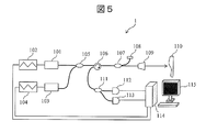
- FIG. 5 is a diagram illustrating a schematic configuration of the distance measuring device 1 according to the first embodiment of the present disclosure.
- the distance measuring apparatus 1 includes semiconductor lasers 101 and 103, arbitrary signal generators 102 and 104, a fiber coupler 105, a circulator 106, a fiber coupler 107, a reference mirror 108, and a collimator lens (for example, a fiber collimator). 109, a fiber coupler 111, light receivers 112 and 113, a computer (PC) 114, and a monitor 115.
- PC computer
- the PC 114 transmits the sweep waveform signal to the arbitrary signal generator 102.
- the optical frequency is swept by modulating the drive current of the semiconductor laser 101 by the arbitrary signal generator 102.
- the PC 114 transmits a sweep waveform signal to the arbitrary signal generator 104.
- the optical signal is swept by modulating the drive current of the semiconductor laser 103 by the arbitrary signal generator 104.
- the frequency of the semiconductor laser 101 and [nu 1 the frequency of the semiconductor laser 103 and [nu 2, [nu 1 and [nu 2 are different frequencies (i.e., the laser wavelength is different).
- the light emitted from the semiconductor lasers 101 and 103 is multiplexed by the fiber coupler 105.
- the combined light passes through the circulator 106 and is branched by the fiber coupler 107.
- a part of the branched light is reflected by the reference mirror 108 and becomes reference light.
- Most of the remaining branched light is applied to the space by the collimator lens 109 and is applied to a measurement object 110 (also referred to as a measurement object).
- the light reflected from the measurement object 110 passes through the collimator lens 109 again and merges with the reference light from the reference mirror 108 at the fiber coupler 107 portion, and is then guided to the fiber coupler 111 by the circulator 106, and the wavelength by the fiber coupler 111. To be separated.
- the light subjected to wavelength separation is detected by a light receiver 112 for the semiconductor laser 101 and a light receiver 113 for the semiconductor laser 103, respectively.
- Each of the light receivers 112 and 113 generates a beat signal due to interference between the reference light and the measurement light.
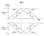
- FIG. 6 is a diagram illustrating an example of a signal (detection signal) detected by the distance measuring apparatus according to the first embodiment.
- FIG. 7 is a flowchart for explaining a process of calculating a distance from the detection signal (distance calculation process).
- the distance calculation process is executed by a processor (CPU or MPU) included in the computer 114. More specifically, a program (distance calculation program) for executing the distance calculation processing according to FIG. 7 is stored in a memory (not shown) of the computer 114, and the processor reads the distance calculation program from the memory. Will be executed.
- the processor of the computer 114 hereinafter simply referred to as “processor” will be described as an operation subject.
- Step 701 The processor A / D converts the signal detected by the light receiver 112 to obtain a digital signal.
- Step 702 The processor cuts out the upstream signal of the frequency sweep from the digital detection signal.
- Step 703 The processor performs FFT processing on the signal cut out in step 702.
- Step 704 The processor detects the peak frequency from the signal subjected to the FFT processing in step 703.
- Step 705 the processor A / D converts the signal detected by the light receiver 113 to obtain a digital signal.
- Step 706 The processor cuts out the upstream signal of the frequency sweep from the digital detection signal.
- Step 707 The processor performs FFT processing on the signal cut out in step 706.
- Step 708 The processor detects the peak frequency from the signal subjected to the FFT processing in Step 707.
- Step 709 The processor removes the Doppler shift from the peak frequency obtained in steps 704 and 708 and calculates an accurate distance. Details of the processing in step 709 are as follows. When the measurement target vibrates, the Doppler shift amount received by the semiconductor laser 101 is expressed by Expression (6).
- Equation (8) makes it possible to obtain an accurate distance without error.
- the distance to the measurement target from which the distance error due to the Doppler shift is removed can be calculated.
- steps 701 to 704 and the processing of steps 705 to 708 are shown to be performed in parallel, but the execution order of each step can be arbitrarily set.
- the beat frequency f b needs to be constant during the modulation period T.
- the change amount of the optical frequency is nonlinear with respect to the change amount of the injection current as a characteristic of the semiconductor laser, there is a problem that the measurement accuracy is deteriorated. Therefore, in the second embodiment, a distance measuring apparatus that performs correction using a reference interferometer having a certain optical path difference is proposed.
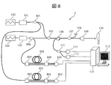
- FIG. 8 is a diagram illustrating a schematic configuration example of the distance measuring device 2 according to the second embodiment.
- the distance measuring device 2 shown in FIG. 8 has the same configuration as that of the distance measuring device 1 shown in FIG. The difference is that the light emitted from the semiconductor laser is branched by a fiber coupler and partially guided to a reference interferometer.
- the light irradiated from the semiconductor laser 101 is branched by the fiber coupler 801.
- One of the branched lights is guided to the fiber coupler 802.
- the light is further branched into two by the fiber coupler 802, provided with a certain optical path difference by the optical fiber 803, and then multiplexed by the fiber coupler 804 and received by the light receiver 805.
- This has the structure of a Mach-Zehnder interferometer, and the light receiver 805 generates a constant beat signal proportional to the optical path difference.
- the light emitted from the semiconductor laser 103 is branched by the fiber coupler 806.
- One of the branched lights is guided to the fiber coupler 807.
- the light is further branched into two by a fiber coupler 807, provided with a certain optical path difference by an optical fiber 808, and then multiplexed by a fiber coupler 809 and received by a light receiver 810.
- This has the structure of a Mach-Zehnder interferometer, and the light receiver 810 generates a constant beat signal proportional to the optical path difference.
- the beat frequency fb needs to be constant during the modulation period T.
- the change amount of the optical frequency is nonlinear with respect to the change amount of the injection current as a characteristic of the semiconductor laser, there is a problem that the measurement accuracy is deteriorated. Therefore, in the third embodiment, a distance measuring device that controls the injection current of the semiconductor laser to make the beat frequency constant is proposed.
- FIG. 9 is a diagram illustrating a schematic configuration example of the distance measuring device 3 according to the third embodiment.
- the distance measuring device 3 in FIG. 9 has the same configuration as that of the distance measuring device 1 in FIG. The difference is that the light emitted from the semiconductor laser is branched by the fiber coupler 901 and part of the light is guided to a feedback mechanism that controls the injection current of the semiconductor laser 101.
- the light emitted from the semiconductor laser 101 is branched by the fiber coupler 901.
- One of the branched lights is guided to a feedback mechanism (feedback circuit) 902.
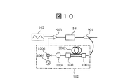
- FIG. 10 is a diagram illustrating an internal configuration example of the feedback mechanism 902.
- the light from the fiber coupler 901 is further branched into two by the fiber coupler 1001, and after a certain optical path difference is provided by the optical fiber 1002, the light is again combined by the fiber coupler 1003 and received by the light receiver 1004.
- This is a structure of a Mach-Zehnder interferometer, and a constant beat signal proportional to the optical path difference is generated in the light receiver 1004.
- the beat signal and the signal from the signal oscillator 1005 are mixed by the mixer 1006, and the current signal corresponding to the difference frequency or the difference phase is added to the current signal from the arbitrary signal generator 102 by the combiner 903, thereby making the beat signal constant. It is controlled to become.
- the light irradiated from the semiconductor laser 103 is branched by the fiber coupler 904.
- One of the branched lights is guided to the feedback mechanism 905.
- the feedback mechanism 905 has the same configuration as the feedback mechanism 902 (see FIG. 10), and the beat signal is generated by adding the output current signal to the current signal from the arbitrary signal generator 104 by the combiner 906. Control to be constant.
- the distance can be measured with high accuracy by using the two light sources linearly swept in frequency and performing the same process as the process described in the first embodiment.
- FIG. 11 is a diagram illustrating a schematic configuration example of the distance measuring device 4 according to the fourth embodiment.
- the distance measuring device 4 is different from the distance measuring device 1 (see FIG. 5) having two light receivers in that there is one light receiver.
- the computer (PC) 114 transmits a sweep waveform signal to the arbitrary signal generator 102.
- the arbitrary signal generator 102 sweeps the optical frequency by modulating the drive current of the semiconductor laser 101.
- the light emitted from the laser passes through the circulator 1101 and is branched by the fiber coupler 1102. A part of the light is reflected by the reference mirror 1103 and becomes the reference light, and most of the remaining light is guided to the WDM coupler 1104.
- the computer (PC) 114 transmits a sweep waveform signal to the arbitrary signal generator 104.
- the arbitrary signal generator 104 sweeps the optical frequency by modulating the drive current of the semiconductor laser 103.
- the light emitted from the laser passes through the circulator 1105, is branched by the fiber coupler 1106, a part of the light is reflected by the reference mirror 1107, and most of the remaining light is guided to the WDM coupler 1104.
- the light combined by the WDM coupler 1104 is applied to the space by the collimator lens (fiber collimator) 109 and is applied to the measurement object 110.
- the light reflected from the measurement object 110 passes through the collimator lens 109 again, is guided to the WDM coupler 1104, and is wavelength-separated by the WDM coupler 1104.
- One light obtained by wavelength separation by the WDM coupler 1104 again passes through the fiber coupler 1102 and the circulator 1101 and is guided to the WDM coupler 1108.
- the other light obtained by wavelength separation by the WDM coupler 1104 again passes through the fiber coupler 1106 and the circulator 1105 and is guided to the WDM coupler 1108.
- the light combined by the WDM coupler 1108 is detected by the light receiver 1109, and a beat signal is generated by the interference between the reference light and the measurement light.
- a beat signal is generated by the interference between the reference light and the measurement light.
- FIG. 12 is a diagram illustrating an example of the beat frequency detected by the light receiver 1109.
- a peak frequency (beat signal detected by the light receiver) 1201 having a low beat frequency indicates a beat frequency corresponding to the semiconductor laser 101 having a small distance difference between the measurement target and the reference mirror.
- a peak frequency (beat signal detected by the light receiver) 1202 having a high frequency indicates a beat frequency corresponding to the semiconductor laser 103 having a large distance difference between the measurement target and the reference mirror.
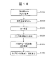
- FIG. 13 is a flowchart for explaining a process of calculating a distance from a detection signal (distance calculation process).
- the distance calculation process is executed by a processor (CPU or MPU) included in the computer 114. More specifically, a program (distance calculation program) for executing the distance calculation processing according to FIG. 7 is stored in a memory (not shown) of the computer 114, and the processor reads the distance calculation program from the memory. Will be executed.
- the processor of the computer 114 hereinafter simply referred to as “processor” will be described as an operation subject.
- Step 1301 The processor A / D converts the signal detected by the light receiver 1109 to obtain a digital signal.
- Step 1302 The processor cuts out a signal in a region corresponding to a half cycle of the frequency sweep cycle from the digital detection signal obtained in step 1301.
- Step 1303 The processor performs FFT processing on the signal cut out in step 1302.
- Step 1304 The processor detects a lower peak frequency from the signal subjected to the FFT processing in step 1303.
- Step 1305 The processor detects the peak frequency having the higher frequency from the signal subjected to the FFT processing in step 1303. Note that the execution order of step 1304 and step 1305 may be reversed.
- Step 1306 The processor can calculate an accurate distance by removing the Doppler shift based on Equation (8) from the two peak frequencies detected in Step 1304 and Step 1305.
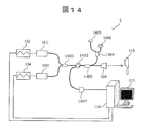
- FIG. 14 is a diagram illustrating a schematic configuration example of the distance measuring device 5 according to the fifth embodiment. Similar to the distance measuring device 4, the distance measuring device 5 includes one light receiver.
- the computer (PC) 114 transmits a sweep waveform signal to the arbitrary signal generator 102.
- the arbitrary signal generator 102 sweeps the optical frequency by modulating the drive current of the semiconductor laser 101.
- the computer (PC) 114 transmits a sweep waveform signal to the arbitrary signal generator 104.
- the arbitrary signal generator 104 sweeps the optical frequency by modulating the drive current of the semiconductor laser 103.
- the light output from the semiconductor laser 101 and the semiconductor laser 103 is multiplexed by the WDM coupler 1401.
- the light combined by the WDM coupler 1401 passes through the circulator 1402 and is branched by the fiber coupler 1403.
- One of the lights obtained by branching is further branched by the WDM coupler 1404 and reflected by the reference mirror 1405 for the semiconductor laser 101 and the reference mirror 1406 for the semiconductor laser 103 to become reference light.
- the other light (most of the light) obtained by branching is irradiated to the space by the collimator lens 109 and irradiated to the measurement object 110.
- the light reflected from the measurement object 110 passes through the collimator lens 109 again, is combined with the reference light from the reference mirrors 1405 and 1406 by the fiber coupler 1403, and then passes through the circulator 1402.
- the light that has passed through the circulator 1402 is detected by the light receiver 1407, and a beat signal is generated due to interference between the reference light and the measurement light.
- a beat signal is generated due to interference between the reference light and the measurement light.
- the distance to the reference mirror is different even if the same measurement target is measured.
- Beat signals can be generated at different positions.
- the subsequent processing contents are the same as those in the fourth embodiment.
- the beat frequency fb needs to be constant during the modulation period T.
- the change amount of the optical frequency is nonlinear with respect to the change amount of the injection current as a characteristic of the semiconductor laser, there is a problem that the measurement accuracy is deteriorated. Therefore, in the sixth embodiment, a distance measuring apparatus that performs correction using a reference interferometer having a certain optical path difference is proposed.
- FIG. 15 is a diagram illustrating a schematic configuration example of the distance measuring device 6 according to the sixth embodiment.
- the distance measuring device 6 in FIG. 15 has the same configuration as the distance measuring device 4 in FIG. The difference is that the light emitted from the semiconductor laser is branched by a fiber coupler and partially guided to a reference interferometer.
- the light output from the semiconductor laser 101 is branched by the fiber coupler 1501.
- One light obtained by the branching is guided to the fiber coupler 1502 and further split into two by the fiber coupler 1502.
- One of the lights further branched by the fiber coupler 1502 is guided to the optical fiber 1505.
- the other of the light further branched by the fiber coupler 1502 passes through the WDM coupler 1503, is guided to the optical fiber 1506, and a certain optical path difference is provided.
- the light that has passed through the optical fiber 1505 passes through the WDM coupler 1508, is combined by the fiber coupler 1509, and is received by the light receiver 1510.
- This is a structure of a Mach-Zehnder interferometer, and the light receiver 1510 generates a constant beat signal proportional to the optical path difference between the optical fiber 1505 and the optical fiber 1506.
- the light output from the semiconductor laser 103 is branched by the fiber coupler 1500.
- One light obtained by branching is guided to the fiber coupler 1504 and further branched into two by the fiber coupler 1504.
- One of the lights further branched by the fiber coupler 1504 is guided to the optical fiber 1507.
- the other of the light further branched by the fiber coupler 1504 passes through the WDM coupler 1503, is guided to the optical fiber 1506, and a certain optical path difference is provided.
- the light that has passed through the optical fiber 1507 passes through the WDM coupler 1508, is combined by the fiber coupler 1509, and is received by the light receiver 1510.
- This is a configuration of a Mach-Zehnder interferometer, and the light receiver 1510 generates a constant beat signal proportional to the optical path difference between the optical fiber 1506 and the optical fiber 1507.
- the seventh embodiment relates to a shape measuring device for measuring the shape of a measurement object using any one of the distance measuring devices 1 to 6 according to the first to sixth embodiments. It is.
- FIG. 16 is a diagram illustrating a schematic configuration example of the shape measuring device 7 according to the seventh embodiment, which includes any one of the distance measuring devices according to the first to sixth embodiments.
- the shape measuring device 7 includes a 3D shape measuring unit 1601, a computer (PC) 114, and a monitor 115.
- PC computer
- the 3D shape measurement unit 1601 measures the 3D shape of the measurement object 110, and includes a distance measurement unit (distance measurement device) 1602 according to any one of the first to sixth embodiments, a one-axis stage 1603, A focus lens 1604 and galvanometer mirrors 1605 and 1606 are provided.
- a distance measurement unit distance measurement device 1602 according to any one of the first to sixth embodiments
- a one-axis stage 1603 A focus lens 1604 and galvanometer mirrors 1605 and 1606 are provided.
- the laser light emitted from the collimator lens 109 of the distance measurement unit 1602 is focus-adjusted on the measurement object 110. Further, by shaking the galvanometer mirrors 1605 and 1606, the measurement surface of the measurement object 110 is scanned two-dimensionally with laser light, and the shape of the measurement object 110 is measured.
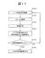
- FIG. 17 is a flowchart for explaining shape measurement processing according to the seventh embodiment.
- the shape measurement process is executed by a processor (CPU or MPU) included in the computer 114. More specifically, a program (shape measurement program) for executing the shape measurement process according to FIG. 17 is stored in a memory (not shown) of the computer 114, and the processor reads the distance calculation program from the memory. Will be executed.
- the processor of the computer 114 hereinafter simply referred to as “processor” will be described as an operation subject.
- Step 1701 The processor scans the laser scanning angle output from the distance measuring unit 1602 based on information on one coordinate point within the input specified range (for example, the user inputs referring to the size of the measurement target 110). Adjust.
- Step 1702 The processor moves the one-axis stage 1603 in the axial direction to focus on the measurement object 110 (focus adjustment).
- Step 1703 The processor executes the processing described in the distance measurement device according to the first to sixth embodiments, and measures the distance to the measurement object 110.
- Step 1704 The processor calculates 3D coordinates of the measurement target 110 from the laser scanning angle determined in step 1701 and the distance measured in step 1703.
- Step 1705 The processor determines whether all of the input designated range has been measured. If all designated ranges (all coordinate points) have been measured (YES in step 1705), the process proceeds to step 1706. If all the specified ranges have not been measured yet (NO in step 1705), the process proceeds to step 1701.
- Step 1706 The processor outputs 3D shape measurement results of all coordinate points in the specified range.
- FIG. 18 is a diagram illustrating a schematic configuration example of an inner diameter measuring device 8 according to the eighth embodiment, which includes any one of the first to sixth embodiments. It is.
- the inner diameter measuring device 8 is a device that measures the inner diameter of the inner diameter measuring object 116, and is a distance measuring unit (distance measuring device) 1802, a single axis stage 1803, and a focus according to any of the first to sixth embodiments.
- a lens 1804, a reflecting prism 1805, a rotary stage 1806, a computer (PC) 114, and a monitor 115 are provided.
- the laser light emitted from the collimator lens 109 of the distance measuring unit 1802 is focused on the inner side surface of the inner diameter measurement target 116.
- each embodiment two light sources are provided to emit light having different wavelengths, but light having different wavelengths may be emitted from one light source. . Therefore, a configuration including the semiconductor lasers 101 and 103 and the arbitrary signal generators 102 and 104 can be referred to as a “light source unit”. Further, although two lights having different wavelengths are used, three or more lights having different wavelengths may be used. In this case, three or more light sources may be used, or three or more lights may be emitted from the light source unit.
- the distance measuring device includes a frequency calculation process for calculating a peak frequency corresponding to light of each wavelength emitted from the light source unit from a signal detected by the light receiving unit, and a peak corresponding to light of each wavelength. And a distance calculation process for calculating a distance by reducing a Doppler shift error caused by the vibration of the measurement target from the frequency. By doing in this way, it becomes possible to measure highly accurate distance (distance from a light source to a measuring object).
- the light source unit of the distance measuring device is configured to sweep and output a plurality of lights so that the frequency sweep periods of the plurality of lights having different wavelengths are shifted by a predetermined period. By doing so, it is not necessary to provide a very long optical fiber (for example, a length of 100 km) in order to provide an optical path difference, and the scale of the distance measuring device can be reduced.
- the emitted light has different optical axes immediately after the emission.
- a multiplexing optical element that combines a plurality of lights into a plurality of coaxial lights is provided so that the measurement target is irradiated with the plurality of coaxial lights.
- a plurality of lights having different wavelengths can be irradiated to the same location to be measured in one measurement, the measurement throughput can be improved, and measurement errors can be reduced.
- the multiplexing optical element for example, a WDM coupler or a dichroic mirror can be used.
- a branching optical element that branches a plurality of coaxial lights is provided in the middle of the optical path from the multiplexing optical element to the measurement target. A part of the light branched by the branching optical element is guided to the reference mirror. Light other than the light guided to the reference mirror is guided to the irradiation optical element and irradiated to the measurement target.
- a fiber coupler can be used as the branching optical element, and a collimator lens can be used as the irradiation optical element.
- the light receiving unit is configured to receive the light reflected by the measurement target according to the wavelength of the emitted light. By doing so, it becomes possible to generate a beat signal due to interference between the reference light and the measurement light (reflected light from the measurement target) for each light having a different wavelength.
- the distance measurement device of the present disclosure may include a calibration interferometer that reduces errors due to nonlinearity of optical frequency sweeping in the light source unit. By doing so, it becomes possible to measure the distance with higher accuracy.
- the distance measuring device includes a feedback mechanism that generates a signal for controlling the injection current of the light source unit from a part of the light emitted from the light source unit and feeds back the signal to the light source unit. May be. By doing so, it becomes possible to measure the distance with higher accuracy.
- the distance L can be calculated by reducing the Doppler shift error based on the following equation.
- T is a modulation period
- ⁇ is a frequency sweep width
- ⁇ 1 and ⁇ 2 are wavelengths (when two lights are used).
- ⁇ t represents a time difference between the reference light and the light reflected from the measurement target
- ⁇ f1 and ⁇ f2 represent Doppler shift amounts of the respective lights
- f beat represents a beat frequency.
- the present embodiment also provides a shape measuring device and an inner diameter measuring device including the above-described distance measuring device.
- the shape measuring device includes a focus lens that focuses the light from the distance measuring device on the shape measurement target, and a mirror that scans the light whose focus is adjusted on the shape measurement target. Then, the shape measuring device measures the three-dimensional shape of the shape measuring object using the distance from the light source unit measured by the distance measuring device to the shape measuring object and the scanning angle of the light whose focus is adjusted, Outputs 3D shape measurement results.
- the inner diameter measuring device includes a focus lens that adjusts the focus of light from the distance measuring device to a shape measurement target, a rotary stage, and a reflecting prism mounted thereon. While the reflecting prism is rotated by the rotating stage, the light whose focus is adjusted is reflected by the reflecting prism at a right angle. By doing in this way, it becomes possible to measure the internal diameter of an internal diameter measurement object.
- the function executed by the processor can also be realized by a program code of software.
- a storage medium in which the program code is recorded is provided to the system or apparatus, and the computer (or CPU or MPU) of the system or apparatus reads the program code stored in the storage medium.
- the program code itself read from the storage medium realizes the functions of the above-described embodiments, and the program code itself and the storage medium storing the program code constitute the present disclosure.
- a storage medium for supplying such program code for example, a flexible disk, CD-ROM, DVD-ROM, hard disk, optical disk, magneto-optical disk, CD-R, magnetic tape, nonvolatile memory card, ROM Etc. are used.
- an OS operating system
- the computer CPU or the like performs part or all of the actual processing based on the instruction of the program code.
- the program code is stored in a storage means such as a hard disk or a memory of a system or apparatus, or a storage medium such as a CD-RW or CD-R
- the computer (or CPU or MPU) of the system or apparatus may read and execute the program code stored in the storage means or the storage medium when used.
- control lines and information lines are those that are considered necessary for the explanation, and not all control lines and information lines on the product are necessarily shown. All the components may be connected to each other.
Landscapes
- Physics & Mathematics (AREA)
- Engineering & Computer Science (AREA)
- General Physics & Mathematics (AREA)
- Computer Networks & Wireless Communication (AREA)
- Radar, Positioning & Navigation (AREA)
- Remote Sensing (AREA)
- Electromagnetism (AREA)
- Optical Radar Systems And Details Thereof (AREA)
- Instruments For Measurement Of Length By Optical Means (AREA)
- Length Measuring Devices By Optical Means (AREA)
Abstract
Priority Applications (3)
| Application Number | Priority Date | Filing Date | Title |
|---|---|---|---|
| PCT/JP2016/063054 WO2017187510A1 (fr) | 2016-04-26 | 2016-04-26 | Dispositif de mesure de distance, procédé de mesure de distance et dispositif de mesure de forme |
| JP2018513983A JPWO2017187510A1 (ja) | 2016-04-26 | 2016-04-26 | 距離計測装置、距離計測方法、及び形状計測装置 |
| US15/751,318 US20180224548A1 (en) | 2016-04-26 | 2016-04-26 | Distance Measuring Apparatus, Distance Measuring Method, and Shape Measuring Apparatus |
Applications Claiming Priority (1)
| Application Number | Priority Date | Filing Date | Title |
|---|---|---|---|
| PCT/JP2016/063054 WO2017187510A1 (fr) | 2016-04-26 | 2016-04-26 | Dispositif de mesure de distance, procédé de mesure de distance et dispositif de mesure de forme |
Publications (1)
| Publication Number | Publication Date |
|---|---|
| WO2017187510A1 true WO2017187510A1 (fr) | 2017-11-02 |
Family
ID=60160386
Family Applications (1)
| Application Number | Title | Priority Date | Filing Date |
|---|---|---|---|
| PCT/JP2016/063054 Ceased WO2017187510A1 (fr) | 2016-04-26 | 2016-04-26 | Dispositif de mesure de distance, procédé de mesure de distance et dispositif de mesure de forme |
Country Status (3)
| Country | Link |
|---|---|
| US (1) | US20180224548A1 (fr) |
| JP (1) | JPWO2017187510A1 (fr) |
| WO (1) | WO2017187510A1 (fr) |
Cited By (30)
| Publication number | Priority date | Publication date | Assignee | Title |
|---|---|---|---|---|
| WO2019186914A1 (fr) * | 2018-03-29 | 2019-10-03 | 三菱電機株式会社 | Dispositif de radar laser |
| US10527412B2 (en) | 2015-10-06 | 2020-01-07 | Bridger Photonics, Inc. | Gas-mapping 3D imager measurement techniques and method of data processing |
| WO2020018805A1 (fr) * | 2018-07-18 | 2020-01-23 | Bridger Photonics, Inc. | Procédés et appareils d'appariement de pics de distance et de suivi de cible de haute précision à l'aide de mesures de lidar fmcw |
| CN110864621A (zh) * | 2019-11-01 | 2020-03-06 | 西安工业大学 | 一种空分式多波长调频连续波激光干涉仪 |
| JP2020046368A (ja) * | 2018-09-20 | 2020-03-26 | 日本製鉄株式会社 | 距離測定方法及び距離測定装置 |
| CN111679284A (zh) * | 2020-06-16 | 2020-09-18 | 中国计量大学 | 一种用于运动目标测量的双激光测距装置及方法 |
| JPWO2019239491A1 (ja) * | 2018-06-12 | 2020-10-01 | 三菱電機株式会社 | 光測距装置及び加工装置 |
| WO2021020242A1 (fr) * | 2019-07-26 | 2021-02-04 | 株式会社SteraVision | Appareil de mesure de distance et de vitesse |
| JP2021523387A (ja) * | 2018-05-10 | 2021-09-02 | アワーズ・テクノロジー・インコーポレイテッド | 同時の測距距離および速度測定のための、複数個のレーザおよびコヒーレント受信器の相補的変調に基づくlidarシステム |
| US11112308B2 (en) | 2017-11-14 | 2021-09-07 | Bridger Photonics, Inc. | Apparatuses and methods for anomalous gas concentration detection |
| EP3879222A1 (fr) | 2020-03-13 | 2021-09-15 | OMRON Corporation | Appareil de mesure d'interférence optique |
| US11422244B2 (en) | 2017-09-25 | 2022-08-23 | Bridger Photonics, Inc. | Digitization systems and techniques and examples of use in FMCW LiDAR methods and apparatuses |
| JP2022145268A (ja) * | 2021-03-19 | 2022-10-03 | 国立大学法人徳島大学 | 距離、速度測定装置及び距離、速度測定方法 |
| US11592563B2 (en) | 2017-10-17 | 2023-02-28 | Bridger Photonics, Inc. | Apparatuses and methods for a rotating optical reflector |
| US11604280B2 (en) | 2017-10-02 | 2023-03-14 | Bridger Photonics, Inc. | Processing temporal segments of laser chirps and examples of use in FMCW LiDAR methods and apparatuses |
| CN115877352A (zh) * | 2022-11-11 | 2023-03-31 | 中国航空工业集团公司西安飞行自动控制研究所 | 一种实时大动态多普勒测速激光雷达的装置及方法 |
| JP2023529564A (ja) * | 2020-05-16 | 2023-07-11 | シルク テクノロジーズ インコーポレイティッド | Lidar出力信号における信号チャープの監視 |
| WO2023171483A1 (fr) * | 2022-03-08 | 2023-09-14 | 株式会社東京精密 | Dispositif de mesure de forme et procédé de mesure de forme |
| US12066353B2 (en) | 2018-02-01 | 2024-08-20 | Bridger Photonics, Inc. | Apparatuses and methods for gas flux measurements |
| WO2024171633A1 (fr) * | 2023-02-17 | 2024-08-22 | 富士フイルム株式会社 | Dispositif, procédé et programme de calibrage de distance et dispositif de mesure de distance |
| WO2024171632A1 (fr) * | 2023-02-17 | 2024-08-22 | 富士フイルム株式会社 | Dispositif de mesure de distance, procédé de mesure de distance et programme |
| WO2024176779A1 (fr) * | 2023-02-24 | 2024-08-29 | 富士フイルム株式会社 | Dispositif de télémétrie laser, procédé de télémétrie laser et programme |
| JPWO2024185395A1 (fr) * | 2023-03-03 | 2024-09-12 | ||
| US12411213B2 (en) | 2021-10-11 | 2025-09-09 | Silc Technologies, Inc. | Separation of light signals in a LIDAR system |
| US12422618B2 (en) | 2022-10-13 | 2025-09-23 | Silc Technologies, Inc. | Buried taper with reflecting surface |
| US12535586B2 (en) | 2018-08-31 | 2026-01-27 | SiLC Technology, Inc. | Reduction of ADC sampling rates in LIDAR systems |
| US12541009B2 (en) | 2021-06-17 | 2026-02-03 | Silc Technologies, Inc. | Scanning multiple LIDAR system output signals |
| US12553995B2 (en) | 2022-02-14 | 2026-02-17 | Silc Technologies, Inc. | Data refinement in optical systems |
| US12578439B2 (en) | 2023-04-11 | 2026-03-17 | Silc Technologies, Inc. | Increasing resolution in imaging systems |
| US12578443B2 (en) | 2022-04-23 | 2026-03-17 | Silc Technologies, Inc. | Data refinement in optical imaging systems |
Families Citing this family (9)
| Publication number | Priority date | Publication date | Assignee | Title |
|---|---|---|---|---|
| US11119193B2 (en) * | 2018-03-28 | 2021-09-14 | Northwestern University | Micro resolution imaging range sensor system |
| EP3581962A1 (fr) * | 2018-06-11 | 2019-12-18 | Hexagon Technology Center GmbH | Procédé de mesure de distance fmcw à deux faisceaux à compensation d'une erreur de mesure de distance dépendante de la vitesse |
| DE102019211832A1 (de) * | 2018-08-23 | 2020-02-27 | Mitutoyo Corporation | Messvorrichtung und messverfahren |
| US11215701B2 (en) * | 2019-09-27 | 2022-01-04 | Aeva, Inc. | Coherent LIDAR |
| JP7654336B2 (ja) * | 2019-10-15 | 2025-04-01 | ソニーセミコンダクタソリューションズ株式会社 | 測距デバイス |
| DE102019135648A1 (de) * | 2019-12-21 | 2021-06-24 | Carl Zeiss Ag | Vorrichtung und Verfahren zur Abstandsermittlung eines Objekts |
| CN116113803B (zh) * | 2020-07-22 | 2025-08-29 | 三菱电机株式会社 | 距离计测装置、距离计测方法以及工作装置 |
| CN112904307A (zh) * | 2021-01-26 | 2021-06-04 | 宁波飞芯电子科技有限公司 | 一种获取距离信息的探测方法及探测系统 |
| CN115396027B (zh) * | 2022-10-31 | 2023-04-11 | 长春理工大学 | 一种飞机间测距通信一体化装置及方法 |
Citations (8)
| Publication number | Priority date | Publication date | Assignee | Title |
|---|---|---|---|---|
| JPH09257415A (ja) * | 1996-03-25 | 1997-10-03 | Senshin Zairyo Riyou Gas Jienereeta Kenkyusho:Kk | 光ファイバセンサ |
| JPH10111361A (ja) * | 1996-10-02 | 1998-04-28 | Tamagawa Seiki Co Ltd | リニア型光位置・速度センサの信号出力方法 |
| JP2000111312A (ja) * | 1998-08-04 | 2000-04-18 | Mitsubishi Heavy Ind Ltd | 光周波数線形掃引装置及び光周波数線形掃引装置のための変調補正デ―タ記録装置 |
| JP2002372580A (ja) * | 2001-06-13 | 2002-12-26 | Mitsubishi Electric Corp | Fm−cwレーダ装置 |
| JP2008531993A (ja) * | 2005-02-17 | 2008-08-14 | メトリス ユーエスエー インク. | 逆チャープfmcwコヒーレントレーザレーダのためのコンパクト光ファイバジオメトリ |
| JP2008275594A (ja) * | 2007-04-03 | 2008-11-13 | Yamatake Corp | 距離・速度計および距離・速度計測方法 |
| JP2012502301A (ja) * | 2008-09-11 | 2012-01-26 | ニコン・メトロロジー・エヌヴェ | 対チャープfmcwコヒーレントレーザレーダー用の小型の光ファイバ配置 |
| JP2014202716A (ja) * | 2013-04-09 | 2014-10-27 | 株式会社日立ハイテクノロジーズ | 距離測定装置 |
Family Cites Families (4)
| Publication number | Priority date | Publication date | Assignee | Title |
|---|---|---|---|---|
| US5715044A (en) * | 1987-08-14 | 1998-02-03 | Boeing North American, Inc. | Laser radar |
| US6153886A (en) * | 1993-02-19 | 2000-11-28 | Nikon Corporation | Alignment apparatus in projection exposure apparatus |
| EP1953567A3 (fr) * | 2007-01-25 | 2010-09-22 | Yamatake Corporation | Dispositif de comptage, mesure de distance, procédé de comptage, et procédé de mesure de distance |
| US9025160B2 (en) * | 2011-01-28 | 2015-05-05 | The Regents Of The University Of Colorado, A Body Corporate | Spectral phase analysis for precision ranging |
-
2016
- 2016-04-26 US US15/751,318 patent/US20180224548A1/en not_active Abandoned
- 2016-04-26 JP JP2018513983A patent/JPWO2017187510A1/ja active Pending
- 2016-04-26 WO PCT/JP2016/063054 patent/WO2017187510A1/fr not_active Ceased
Patent Citations (8)
| Publication number | Priority date | Publication date | Assignee | Title |
|---|---|---|---|---|
| JPH09257415A (ja) * | 1996-03-25 | 1997-10-03 | Senshin Zairyo Riyou Gas Jienereeta Kenkyusho:Kk | 光ファイバセンサ |
| JPH10111361A (ja) * | 1996-10-02 | 1998-04-28 | Tamagawa Seiki Co Ltd | リニア型光位置・速度センサの信号出力方法 |
| JP2000111312A (ja) * | 1998-08-04 | 2000-04-18 | Mitsubishi Heavy Ind Ltd | 光周波数線形掃引装置及び光周波数線形掃引装置のための変調補正デ―タ記録装置 |
| JP2002372580A (ja) * | 2001-06-13 | 2002-12-26 | Mitsubishi Electric Corp | Fm−cwレーダ装置 |
| JP2008531993A (ja) * | 2005-02-17 | 2008-08-14 | メトリス ユーエスエー インク. | 逆チャープfmcwコヒーレントレーザレーダのためのコンパクト光ファイバジオメトリ |
| JP2008275594A (ja) * | 2007-04-03 | 2008-11-13 | Yamatake Corp | 距離・速度計および距離・速度計測方法 |
| JP2012502301A (ja) * | 2008-09-11 | 2012-01-26 | ニコン・メトロロジー・エヌヴェ | 対チャープfmcwコヒーレントレーザレーダー用の小型の光ファイバ配置 |
| JP2014202716A (ja) * | 2013-04-09 | 2014-10-27 | 株式会社日立ハイテクノロジーズ | 距離測定装置 |
Cited By (60)
| Publication number | Priority date | Publication date | Assignee | Title |
|---|---|---|---|---|
| US12510354B2 (en) | 2015-10-06 | 2025-12-30 | Bridger Photonics, Inc. | Gas-mapping 3D imager measurement techniques and method of data processing |
| US10527412B2 (en) | 2015-10-06 | 2020-01-07 | Bridger Photonics, Inc. | Gas-mapping 3D imager measurement techniques and method of data processing |
| US12379210B2 (en) | 2015-10-06 | 2025-08-05 | Bridger Photonics, Inc. | High-sensitivity gas-mapping 3D imager and method of operation |
| US11391567B2 (en) | 2015-10-06 | 2022-07-19 | Bridger Photonics, Inc. | Gas-mapping 3D imager measurement techniques and method of data processing |
| US11422244B2 (en) | 2017-09-25 | 2022-08-23 | Bridger Photonics, Inc. | Digitization systems and techniques and examples of use in FMCW LiDAR methods and apparatuses |
| US11604280B2 (en) | 2017-10-02 | 2023-03-14 | Bridger Photonics, Inc. | Processing temporal segments of laser chirps and examples of use in FMCW LiDAR methods and apparatuses |
| US11921211B2 (en) | 2017-10-17 | 2024-03-05 | Bridger Photonics, Inc. | Apparatuses and methods for a rotating optical reflector |
| US11592563B2 (en) | 2017-10-17 | 2023-02-28 | Bridger Photonics, Inc. | Apparatuses and methods for a rotating optical reflector |
| US11692900B2 (en) | 2017-11-14 | 2023-07-04 | Bridger Photonics, Inc. | Apparatuses and methods for anomalous gas concentration detection |
| US11112308B2 (en) | 2017-11-14 | 2021-09-07 | Bridger Photonics, Inc. | Apparatuses and methods for anomalous gas concentration detection |
| US12553789B2 (en) | 2017-11-14 | 2026-02-17 | Bridger Photonics, Inc. | Apparatuses and methods for anomalous gas concentration detection |
| US12066353B2 (en) | 2018-02-01 | 2024-08-20 | Bridger Photonics, Inc. | Apparatuses and methods for gas flux measurements |
| JPWO2019186914A1 (ja) * | 2018-03-29 | 2020-06-18 | 三菱電機株式会社 | レーザレーダ装置 |
| WO2019186914A1 (fr) * | 2018-03-29 | 2019-10-03 | 三菱電機株式会社 | Dispositif de radar laser |
| JP2021523387A (ja) * | 2018-05-10 | 2021-09-02 | アワーズ・テクノロジー・インコーポレイテッド | 同時の測距距離および速度測定のための、複数個のレーザおよびコヒーレント受信器の相補的変調に基づくlidarシステム |
| JP7274571B2 (ja) | 2018-05-10 | 2023-05-16 | アワーズ テクノロジー リミテッド ライアビリティー カンパニー | 同時の測距距離および速度測定のための、複数個のレーザおよびコヒーレント受信器の相補的変調に基づくlidarシステム |
| JP2021531475A (ja) * | 2018-05-10 | 2021-11-18 | アワーズ テクノロジー リミテッド ライアビリティー カンパニー | 同時の測距距離および速度測定のための、光変調器およびコヒーレント受信器に基づくlidarシステム |
| JP2021526650A (ja) * | 2018-05-10 | 2021-10-07 | アワーズ テクノロジー リミテッド ライアビリティー カンパニー | 標的環境の同時のビーム走査のための多チャネルレーザモジュールに基づくlidarシステム |
| JP7498338B2 (ja) | 2018-05-10 | 2024-06-11 | オーロラ・オペレイションズ・インコーポレイティッド | Lidarシステム、標的の距離及び速度を決定する方法、集積フォトニックチップ |
| JP7169436B2 (ja) | 2018-05-10 | 2022-11-10 | アワーズ テクノロジー リミテッド ライアビリティー カンパニー | 同時の測距距離および速度測定のための、光変調器およびコヒーレント受信器に基づくlidarシステム |
| US12210099B2 (en) | 2018-05-10 | 2025-01-28 | Aurora Operations, Inc. | LIDAR system based on multi-channel laser module for simultaneous beam scanning of target environment |
| US12099120B2 (en) | 2018-05-10 | 2024-09-24 | Aurora Operations, Inc. | LIDAR system based on complementary modulation of multiple lasers and coherent receiver for simultaneous range and velocity measurement |
| JP2023109900A (ja) * | 2018-05-10 | 2023-08-08 | アワーズ テクノロジー リミテッド ライアビリティー カンパニー | 標的環境の同時のビーム走査のための多チャネルレーザモジュールに基づくlidarシステム |
| JP7284808B2 (ja) | 2018-05-10 | 2023-05-31 | アワーズ テクノロジー リミテッド ライアビリティー カンパニー | 標的環境の同時のビーム走査のための多チャネルレーザモジュールに基づくlidarシステム |
| JPWO2019239491A1 (ja) * | 2018-06-12 | 2020-10-01 | 三菱電機株式会社 | 光測距装置及び加工装置 |
| US11977157B2 (en) | 2018-06-12 | 2024-05-07 | Mitsubishi Electric Corporation | Optical distance measurement device and machining device |
| US12153135B2 (en) | 2018-07-18 | 2024-11-26 | Bridger Photonics, Inc. | Methods and apparatuses for range peak pairing and high-accuracy target tracking using FMCW LADAR measurements |
| WO2020018805A1 (fr) * | 2018-07-18 | 2020-01-23 | Bridger Photonics, Inc. | Procédés et appareils d'appariement de pics de distance et de suivi de cible de haute précision à l'aide de mesures de lidar fmcw |
| US12535586B2 (en) | 2018-08-31 | 2026-01-27 | SiLC Technology, Inc. | Reduction of ADC sampling rates in LIDAR systems |
| JP7070281B2 (ja) | 2018-09-20 | 2022-05-18 | 日本製鉄株式会社 | 距離測定方法及び距離測定装置 |
| JP2020046368A (ja) * | 2018-09-20 | 2020-03-26 | 日本製鉄株式会社 | 距離測定方法及び距離測定装置 |
| WO2021020242A1 (fr) * | 2019-07-26 | 2021-02-04 | 株式会社SteraVision | Appareil de mesure de distance et de vitesse |
| JP7315154B2 (ja) | 2019-07-26 | 2023-07-26 | 株式会社SteraVision | 距離及び速度測定装置 |
| JPWO2021020242A1 (fr) * | 2019-07-26 | 2021-02-04 | ||
| CN110864621A (zh) * | 2019-11-01 | 2020-03-06 | 西安工业大学 | 一种空分式多波长调频连续波激光干涉仪 |
| US11578963B2 (en) | 2020-03-13 | 2023-02-14 | Omron Corporation | Optical interference measurement apparatus |
| EP3879222A1 (fr) | 2020-03-13 | 2021-09-15 | OMRON Corporation | Appareil de mesure d'interférence optique |
| JP2023529564A (ja) * | 2020-05-16 | 2023-07-11 | シルク テクノロジーズ インコーポレイティッド | Lidar出力信号における信号チャープの監視 |
| JP7746291B2 (ja) | 2020-05-16 | 2025-09-30 | シルク テクノロジーズ インコーポレイティッド | Lidar出力信号における信号チャープの監視 |
| CN111679284A (zh) * | 2020-06-16 | 2020-09-18 | 中国计量大学 | 一种用于运动目标测量的双激光测距装置及方法 |
| CN111679284B (zh) * | 2020-06-16 | 2024-02-09 | 中国计量大学 | 一种用于运动目标测量的双激光测距装置及方法 |
| JP7654246B2 (ja) | 2021-03-19 | 2025-04-01 | 国立大学法人徳島大学 | 距離、速度測定装置及び距離、速度測定方法 |
| JP2022145268A (ja) * | 2021-03-19 | 2022-10-03 | 国立大学法人徳島大学 | 距離、速度測定装置及び距離、速度測定方法 |
| US12541009B2 (en) | 2021-06-17 | 2026-02-03 | Silc Technologies, Inc. | Scanning multiple LIDAR system output signals |
| US12411213B2 (en) | 2021-10-11 | 2025-09-09 | Silc Technologies, Inc. | Separation of light signals in a LIDAR system |
| US12553995B2 (en) | 2022-02-14 | 2026-02-17 | Silc Technologies, Inc. | Data refinement in optical systems |
| WO2023171483A1 (fr) * | 2022-03-08 | 2023-09-14 | 株式会社東京精密 | Dispositif de mesure de forme et procédé de mesure de forme |
| GB2632076A (en) * | 2022-03-08 | 2025-01-22 | Tokyo Seimitsu Co Ltd | Shape measuring device and shape measuring method |
| JP2023131005A (ja) * | 2022-03-08 | 2023-09-21 | 株式会社東京精密 | 形状測定装置及び形状測定方法。 |
| JP7755788B2 (ja) | 2022-03-08 | 2025-10-17 | 株式会社東京精密 | 形状測定装置及び形状測定方法 |
| US12578443B2 (en) | 2022-04-23 | 2026-03-17 | Silc Technologies, Inc. | Data refinement in optical imaging systems |
| US12422618B2 (en) | 2022-10-13 | 2025-09-23 | Silc Technologies, Inc. | Buried taper with reflecting surface |
| CN115877352A (zh) * | 2022-11-11 | 2023-03-31 | 中国航空工业集团公司西安飞行自动控制研究所 | 一种实时大动态多普勒测速激光雷达的装置及方法 |
| WO2024171633A1 (fr) * | 2023-02-17 | 2024-08-22 | 富士フイルム株式会社 | Dispositif, procédé et programme de calibrage de distance et dispositif de mesure de distance |
| WO2024171632A1 (fr) * | 2023-02-17 | 2024-08-22 | 富士フイルム株式会社 | Dispositif de mesure de distance, procédé de mesure de distance et programme |
| WO2024176779A1 (fr) * | 2023-02-24 | 2024-08-29 | 富士フイルム株式会社 | Dispositif de télémétrie laser, procédé de télémétrie laser et programme |
| JP7796939B2 (ja) | 2023-03-03 | 2026-01-09 | 富士フイルム株式会社 | 計測装置、計測システム、及び計測方法 |
| WO2024185395A1 (fr) * | 2023-03-03 | 2024-09-12 | 富士フイルム株式会社 | Dispositif de mesure, système de mesure et procédé de mesure |
| JPWO2024185395A1 (fr) * | 2023-03-03 | 2024-09-12 | ||
| US12578439B2 (en) | 2023-04-11 | 2026-03-17 | Silc Technologies, Inc. | Increasing resolution in imaging systems |
Also Published As
| Publication number | Publication date |
|---|---|
| JPWO2017187510A1 (ja) | 2018-07-19 |
| US20180224548A1 (en) | 2018-08-09 |
Similar Documents
| Publication | Publication Date | Title |
|---|---|---|
| JPWO2017187510A1 (ja) | 距離計測装置、距離計測方法、及び形状計測装置 | |
| US11467282B2 (en) | Chirped coherent laser radar system and method | |
| US11105926B2 (en) | Phase difference frequency generating method, phase difference frequency generating device and electronic distance meter | |
| EP2871493B1 (fr) | Détermination de position au moyen de télémétrie laser d'onde synthétique | |
| JP6303026B2 (ja) | 計測方法および装置 | |
| JP5336921B2 (ja) | 振動計測装置及び振動計測方法 | |
| EP2871492B1 (fr) | Capteurs de télémétrie laser à ondes synthétiques et procédés | |
| JP2011522216A (ja) | 対物距離計測方法及び装置 | |
| EP3465269A1 (fr) | Système lidar cohérent utilisant une modulation à bande latérale unique à suppression de porteuse accordable | |
| US20240004044A1 (en) | Apparatus and method for measuring distant to and/or velocity of physical object | |
| JP2012502301A (ja) | 対チャープfmcwコヒーレントレーザレーダー用の小型の光ファイバ配置 | |
| JP2015094760A5 (fr) | ||
| JP2020008496A (ja) | 距離測定装置、距離測定方法、及び立体形状測定装置 | |
| US9798004B2 (en) | Laser ranging sensors and methods that use a ladder of synthetic waves having increasing wavelengths to calculate a distance measurement | |
| JP7272327B2 (ja) | 光ファイバ特性測定装置、光ファイバ特性測定プログラム、及び光ファイバ特性測定方法 | |
| JP5412209B2 (ja) | 光周波数領域反射測定方法及び光周波数領域反射測定装置 | |
| JP2018059789A (ja) | 距離測定装置及び距離測定方法 | |
| WO2014045655A1 (fr) | Procédé de mesure de distance et dispositif associé | |
| JP2013033014A (ja) | ドップラー振動計測装置及びドップラー振動計測方法 | |
| JP6653052B2 (ja) | レーザー測距装置およびレーザー測距方法 | |
| JP6554755B2 (ja) | 振動計測装置及び振動計測方法 | |
| CN114514409B (zh) | 光距离测定装置以及加工装置 | |
| JP2006078446A (ja) | 干渉測定方法および干渉測定装置 | |
| JP2025086558A (ja) | 風速検出装置及び風速検出方法 | |
| JP2011196695A (ja) | オプティカル・コヒーレンス・トモグラフィー装置とその光源 |
Legal Events
| Date | Code | Title | Description |
|---|---|---|---|
| ENP | Entry into the national phase |
Ref document number: 2018513983 Country of ref document: JP Kind code of ref document: A |
|
| WWE | Wipo information: entry into national phase |
Ref document number: 15751318 Country of ref document: US |
|
| NENP | Non-entry into the national phase |
Ref country code: DE |
|
| 121 | Ep: the epo has been informed by wipo that ep was designated in this application |
Ref document number: 16900383 Country of ref document: EP Kind code of ref document: A1 |
|
| 122 | Ep: pct application non-entry in european phase |
Ref document number: 16900383 Country of ref document: EP Kind code of ref document: A1 |