WO2017187521A1 - Dispositif de montage de composant thermogène - Google Patents
Dispositif de montage de composant thermogène Download PDFInfo
- Publication number
- WO2017187521A1 WO2017187521A1 PCT/JP2016/063087 JP2016063087W WO2017187521A1 WO 2017187521 A1 WO2017187521 A1 WO 2017187521A1 JP 2016063087 W JP2016063087 W JP 2016063087W WO 2017187521 A1 WO2017187521 A1 WO 2017187521A1
- Authority
- WO
- WIPO (PCT)
- Prior art keywords
- heat generating
- generating component
- bolt
- base
- base plate
- Prior art date
- Legal status (The legal status is an assumption and is not a legal conclusion. Google has not performed a legal analysis and makes no representation as to the accuracy of the status listed.)
- Ceased
Links
Images


Classifications
-
- F—MECHANICAL ENGINEERING; LIGHTING; HEATING; WEAPONS; BLASTING
- F16—ENGINEERING ELEMENTS AND UNITS; GENERAL MEASURES FOR PRODUCING AND MAINTAINING EFFECTIVE FUNCTIONING OF MACHINES OR INSTALLATIONS; THERMAL INSULATION IN GENERAL
- F16B—DEVICES FOR FASTENING OR SECURING CONSTRUCTIONAL ELEMENTS OR MACHINE PARTS TOGETHER, e.g. NAILS, BOLTS, CIRCLIPS, CLAMPS, CLIPS OR WEDGES; JOINTS OR JOINTING
- F16B5/00—Joining sheets or plates, e.g. panels, to one another or to strips or bars parallel to them
- F16B5/02—Joining sheets or plates, e.g. panels, to one another or to strips or bars parallel to them by means of fastening members using screw-thread
-
- F—MECHANICAL ENGINEERING; LIGHTING; HEATING; WEAPONS; BLASTING
- F16—ENGINEERING ELEMENTS AND UNITS; GENERAL MEASURES FOR PRODUCING AND MAINTAINING EFFECTIVE FUNCTIONING OF MACHINES OR INSTALLATIONS; THERMAL INSULATION IN GENERAL
- F16B—DEVICES FOR FASTENING OR SECURING CONSTRUCTIONAL ELEMENTS OR MACHINE PARTS TOGETHER, e.g. NAILS, BOLTS, CIRCLIPS, CLAMPS, CLIPS OR WEDGES; JOINTS OR JOINTING
- F16B23/00—Specially shaped nuts or heads of bolts or screws for rotations by a tool
-
- H—ELECTRICITY
- H05—ELECTRIC TECHNIQUES NOT OTHERWISE PROVIDED FOR
- H05K—PRINTED CIRCUITS; CASINGS OR CONSTRUCTIONAL DETAILS OF ELECTRIC APPARATUS; MANUFACTURE OF ASSEMBLAGES OF ELECTRICAL COMPONENTS
- H05K7/00—Constructional details common to different types of electric apparatus
- H05K7/20—Modifications to facilitate cooling, ventilating, or heating
Definitions
- the present invention relates to a heat generating component mounting apparatus for mounting a high-weight heat generating element.
- a reactor that is a winding component is used as an essential component.
- the winding parts constituting the reactor are made of iron and copper, and thus have a weight, and have a function of converting magnetic force into heat, so that the amount of heat generated is also large. Therefore, in order to operate the reactor with high accuracy, it is essential to have a mounting structure that can securely fix the heat-generating component that is heavy while effectively dissipating heat.
- a heavy heat-generating component is placed on a non-ferrous metal base plate having a female screw and excellent in heat dissipation, and a ferrous metal bolt is passed over the base plate.
- the heavy heat-generating parts are fixed by screwing. Since the heavy heat-generating component directly contacts the base plate, effective heat dissipation of the heavy heat-generating component is realized.
- non-ferrous metal which is a non-magnetic material
- a non-magnetic material for the base plate for heat radiation that is brought into direct contact with a heat-generating component using a magnetic material such as a reactor.
- a ferrous metal for the bolt.
- the present invention has been made in view of the above, and a heat generating component capable of effectively releasing heat by bringing a heavy heat generating component into direct contact with the base plate and securely fixing the heat generating component to the base plate.
- the purpose is to obtain a mounting device.
- the present invention provides a bolt including a male screw part, a bolt body part, and a bolt head, and a mounting part having a female screw part screwed into the male screw part.
- a heat generating component having an insertion hole through which the bolt is inserted, a male screw portion of the bolt, a through hole through which the bolt main body portion passes, and a fixing portion for fixing the bolt head, and a first main surface and a second main surface
- a base plate having a surface. The heat generating component is in contact with and fixed to the first main surface of the base plate by the mounting component.
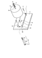
- FIG. 1 is an exploded perspective view showing a heat generating component mounting apparatus according to Embodiment 1.
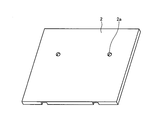
- the perspective view of the base board used for Embodiment 1 The perspective view of the base board used for Embodiment 1
- FIG. FIG. 6 is an exploded perspective view showing a heat generating component mounting apparatus according to a second embodiment.
- FIG. 6 is an exploded perspective view showing a heat generating component mounting apparatus according to Embodiment 3.
- the perspective view of the base base used for Embodiment 3 The perspective view of the base base used for Embodiment 3
- FIG. FIG. 6 is an exploded perspective view showing a heat generating component mounting apparatus according to a fourth embodiment.
- FIG. 6 is an exploded perspective view showing a heat generating component mounting apparatus according to a fifth embodiment.
- the front view which shows the heat-emitting component attachment apparatus of Embodiment 5 The perspective view of the base board used for Embodiment 5
- the perspective view of the base board used for Embodiment 5 The perspective view which shows the heat-emitting component attachment apparatus of Embodiment 6.
- FIG. 7 is an exploded perspective view showing a heat generating component mounting apparatus according to a seventh embodiment.
- the front view which shows the heat-emitting component attachment apparatus of Embodiment 7 The perspective view of the base base used for Embodiment 7
- the perspective view of the base base used for Embodiment 7 The perspective view which shows the heat-emitting component attachment apparatus of Embodiment 8.
- FIG. 9 is an exploded perspective view showing a heat generating component mounting apparatus according to an eighth embodiment.
- FIG. 10 is an exploded perspective view showing a heat generating component mounting apparatus according to the tenth embodiment. Front view showing a heat generating component mounting apparatus according to Embodiment 10. The perspective view which shows the heat-emitting component attachment apparatus of Embodiment 11.
- FIG. 10 is an exploded perspective view showing a heat generating component mounting apparatus according to the tenth embodiment. Front view showing a heat generating component mounting apparatus according to Embodiment 10. The perspective view which shows the heat-emitting component attachment apparatus of Embodiment 11.
- FIG. 14 is a perspective view showing a heat generating component mounting apparatus according to Embodiment 12; The disassembled perspective view which shows the heat-emitting component attachment apparatus of Embodiment 12.
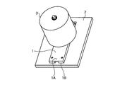
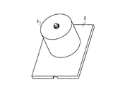
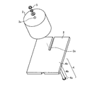
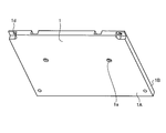
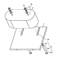
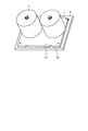
- FIG. 1 is a perspective view showing a heat generating component mounting device according to the first embodiment
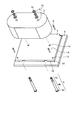
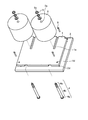
- FIG. 2 is an exploded perspective view showing the heat generating component mounting device according to the first embodiment
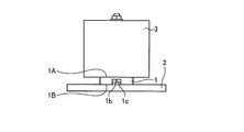
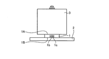
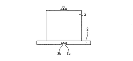
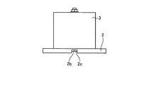
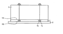
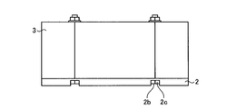
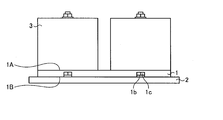
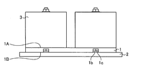
- FIG. 3 is a front view showing the heat generating component mounting device according to the first embodiment.
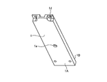
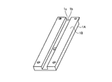
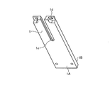
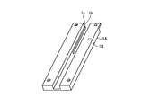
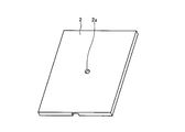
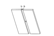
- FIG. 4 and 5 are perspective views of a base plate used in the heat generating component mounting apparatus of the first embodiment.
- the heating component mounting apparatus includes a base plate 1, a base base 2 that is mounted on the base plate 1, a reactor that is a heating component 3 that is mounted on the base plate 1, and the heating component 3 on the base plate 1.
- a bolt 4 for mounting and a nut 5 constituting a mounting part screwed onto the bolt 4 are provided.
- the base plate 1 and the base base 2 are made of an aluminum plate, and the bolt 4 and the nut 5 are made of stainless steel.
- the base plate 1 is fixed to the base base 2 by four screws 6.
- the bolt 4 includes a bolt head 4a, a bolt main body portion 4b, and a male screw portion 4c.
- the nut 5 is an attachment part including a female screw portion 5 c that is screwed into the male screw portion 4 c of the bolt 4.
- the heat generating component 3 has an insertion hole 3a through which the bolt 4 is inserted.
- the base plate 1 has a first main surface 1A that is a contact surface with the heat generating component 3 and a second main surface 1B that is a contact surface with the base base 2, and a male screw portion 4c of the bolt 4; A round-shaped through hole 1a that passes through the bolt body 4b and prevents the bolt head 4a from entering is provided.
- the heat generating component 3 comes into contact with and is fixed to the first main surface 1A of the base plate 1 by screwing the nut 5 and the bolt 4 together.
- the base plate 1 and the base base 2 are made of non-ferrous metal having heat dissipation, and the bolt 4 and the nut 5 are made of ferrous metal.
- the reactor as the heat generating component 3 has a structure in which the winding is housed in a cylindrical core case, and the lead wire is led out from the side surface.
- the base plate 1 has a round through hole 1a for passing the bolt 4, a bolt head fixing groove 1b for preventing and fixing the rotation of the bolt head 4a, and a bolt head storage space 1c. And a fixing portion 1 d for fixing to the base base 2.
- the width of the bolt head fixing groove 1b is determined according to the shape of the bolt head 4a. When the bolt head 4a is a regular polygon, the width of the bolt head fixing groove 1b is approximately the same as the distance between opposite sides parallel to each other, and is smaller than the radius of the circumscribed circle of the regular polygon. It is determined to satisfy.
- the fixing portion 1d is a screw hole that constitutes a female screw. As shown in FIG. 2, the base plate 1 is fixed by screwing a screw 6 into the mounting portion 2 d of the base base 2.
- the bolt 4 When mounting, as shown in FIG. 2, first, the bolt 4 is passed through the circular through hole 1a of the base plate 1, and the bolt head 4a is fitted into the bolt head fixing groove 1b and the bolt head storage space 1c. Next, the second main surface 1B on which the bolt head 4a of the base plate 1 is disposed is brought into surface contact with the base base 2, and the fixing portion 1d of the base plate 1 with the base base 2 and the base plate 1 of the base base 2 are placed. And the mounting portion 2d are screwed together with the screw 6.
- the screw 6 is selected so that the torque is sufficiently smaller than that of the bolt 4 and there is no destruction of the threaded portion due to screwing.
- the bolt head 4 a is fixed by the bolt head fixing groove 1 b of the base plate 1, so that the bolt head 4 a rotates with the rotational force when the nut 5 is screwed.
- the bolt 4 and the nut 5 can be screwed together simply by rotating the nut 5 side.
- the bolt 4 for fixing the heat generating component 3 protrudes from the base plate 1, and thus a space for passing the bolt 4 of the heat generating component 3 through the bolt 4. Since the position of the heat generating component 3 is determined simply by passing through the insertion hole 3a, the mounting operation of the heat generating component 3 becomes easy. Further, since the insertion hole 3a provided in the heat generating component 3 is provided corresponding to the through hole 1a of the base plate 1, the assembly positioning is facilitated.
- the heat generating component 3 does not fall even if the bolt 4 and the nut 5 are not screwed together.
- the screwing of the bolt 4 and the nut 5 is performed on the bolt side protruding from the heat generating component 3, the operator can visually confirm the screwing position or the screwing condition. Therefore, it is possible to suppress the occurrence of inappropriate screwing or screwing part breakage. Further, since the heat generating component 3 can be supported with the bolt 4 penetrating during the assembling operation or the disassembling operation, the heat generating component is not likely to fall, and the operation can be performed safely.
- the heat-generating component 3 having a heavy weight is fixed together with the bolt head 4a and the base plate 1 by screwing a bolt 4 made of ferrous metal and a nut 5 made of ferrous metal. There is no screwing between the heat generating component 3 made of metal and the bolt 4 made of iron-based metal, and there is no fear of destruction of the screwed portion.
- the base plate 1 to which the heat generating component 3 is fixed and the base base 2 are separated, the base plate 1 and the base base 2 are handled separately during assembly and removal. And assembly work is easy.
- the fixing portion is constituted by a bolt head fixing groove 1b provided in the base plate 1, and the width of the bolt head fixing groove 1b is approximately the same as the distance between mutually parallel sides of the bolt head 4a made of a regular polygon. And by making it smaller than the radius of the circumscribed circle of a regular polygon, rotation of the bolt head 4a can be prevented easily and mounting
- the existing heat generating component 3 attached at the attachment portion 2d is changed to another heat generating component 3 fixed with the bolt 4.
- the base plate 1 By providing the base plate 1 with the same structure as the mounting portion 2d for the existing heat generating component 3, it can be replaced with another heat generating component 3 regardless of the shape of the mounting portion 2d.
- FIG. 6 is a perspective view showing a heat generating component mounting device according to the second embodiment
- FIG. 7 is an exploded perspective view showing the heat generating component mounting device according to the second embodiment
- FIG. 8 is a front view showing the heat generating component mounting device according to the second embodiment.
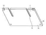
- FIG. 9 and 10 are perspective views of a base plate used in the heat generating component mounting apparatus according to the second embodiment.
- the through hole provided in the base plate 1 is the round through hole 1a in the first embodiment, whereas the heat generating component mounting device in the second embodiment is configured by the U-shaped through hole 1e. Is different.
- the base plate 1 includes a U-shaped through hole 1e extending from an end surface through which the bolt 4 is passed, a bolt head fixing groove 1b for preventing the bolt head 4a from rotating, a bolt head storage space 1c, and a base base 2. It has the fixing
- the other parts are the same as those in the first embodiment, and the description is omitted here.
- the bolt 4 When assembling, the bolt 4 is passed through the U-shaped through hole 1e of the base plate 1 and the bolt head 4a is fitted into the bolt head fixing groove 1b and the bolt head storage space 1c. A surface of the base plate 1 on which the bolt head 4a is disposed is brought into surface contact with the base base 2, and a fixing portion 1d of the base plate 1 with the base plate 2 and a mounting portion 2d of the base plate 2 with the base plate 1 are provided. Screwed with screws 6. As in the first embodiment, the screw 6 has a torque sufficiently smaller than that of the bolt 4 and does not break the screw portion due to screwing.
- an insertion hole 3a for passing the bolt 4 of the heat generating component 3 is passed through the first main surface 1A from which the male screw portion 4c of the bolt 4 of the base plate 1 protrudes, and the male screw portion 4c of the bolt 4 protruding from the heat generating component 3 is inserted. Screwed with the nut 5. At this time, even if the bolt 4 is screwed with the nut 5, the bolt head 4 a is fixed to the bolt head fixing groove 1 b of the base plate 1, so that the bolt head 4 a rotates with the rotational force at the time of nut screwing. The bolt 4 and the nut 5 can be screwed together simply by rotating the nut side.
- the bolt head 4a is simply passed through from the end face side of the U-shaped through hole 1e.
- the head 4a can be fitted into the bolt head fixing groove 1b. Since the bolt head 4a can be fitted into the bolt head fixing groove 1b without passing the bolt 4 from the back surface of the base plate 1, assembly work is easy.
- FIG. 11 is a perspective view showing a heat generating component mounting apparatus according to the third embodiment
- FIG. 12 is an exploded perspective view showing the heat generating component mounting apparatus according to the third embodiment
- FIG. 13 is a front view showing the heat generating component mounting apparatus according to the third embodiment.
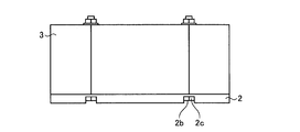
- FIG. 14 and 15 are perspective views of a base base used in the heat generating component mounting apparatus according to the third embodiment.
- the heat generating component 3 is fixed by being brought into contact with the base plate 1, whereas in the third embodiment, the heat generating component 3 is directly applied to the base base 2 instead of the base plate 1. It is fixed in contact.
- the base 2 has a round through hole 2a for passing the bolt 4, a bolt head fixing groove 2b for preventing the bolt head 4a from rotating, and a bolt head storage space 2c.
- the other parts are the same as those in the first embodiment, and the description is omitted here.
- the bolt 4 When assembling, the bolt 4 is passed through the circular through hole 2a of the base base 2 and the bolt head 4a is fitted into the bolt head fixing groove 2b and the bolt head storage space 2c.
- An insertion hole 3 a for passing the bolt of the heat generating component 3 is passed through the surface of the base base 2 from which the threaded portion of the bolt 4 protrudes, and the bolt 4 protruding from the heat generating component 3 is screwed with a nut 5.
- the bolt 4 for fixing the heat generating component 3 protrudes from the base base 2, so that the position of the heat generating component 3 is determined. Since the position of the heat generating component 3 is determined simply by passing the bolt 4 through the insertion hole 3a that is a space for passing the bolt of the heat generating component 3, the mounting operation of the heat generating component 3 is facilitated. As described above, the heat generating component 3 may be directly attached to the base base 2 without the base plate 1.
- the circular through hole 2a for passing the bolt 4 through the base base 2, the bolt head fixing groove 2b for preventing the bolt head 4a from rotating, and the bolt head storage space 2c are provided.
- the base plate 1 is unnecessary.
- it is effective at the time of new design in which it is determined that the heat generating component 3 is attached to the base base 2, and the number of work steps during assembly work can be reduced.
- FIG. 16 is a perspective view showing a heat generating component mounting apparatus according to the fourth embodiment
- FIG. 17 is an exploded perspective view showing the heat generating component mounting apparatus according to the fourth embodiment
- FIG. 18 is a front view showing the heat generating component mounting apparatus according to the fourth embodiment
- FIG. 19 and 20 are perspective views of a base base used in the heat generating component mounting apparatus according to the fourth embodiment.
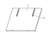
- the heat generating component 3 is fixed by being brought into contact with the base plate 1 having the U-shaped through hole 1e extending from the end face through which the bolt 4 is passed. Instead of the base plate, the heat generating component 3 is directly brought into contact with and fixed to the base base 2.
- the base base 2 has a U-shaped through hole 2e extending from an end face for passing the bolt 4, a bolt head fixing groove 2b for preventing the bolt head 4a from rotating, and a bolt head storage space 2c.
- Others are the same as those in the first and second embodiments, and thus the description thereof is omitted here, but the same reference numerals are given to the same portions.
- the bolt 4 When assembling, the bolt 4 is passed through the U-shaped through hole 2e provided in the base base 2, and the bolt head 4a is fitted into the bolt head fixing groove 2b and the bolt head storage space 2c. Next, an insertion hole 3a for passing the bolt of the heat generating component 3 is passed through the surface of the base base 2 where the screw portion of the bolt 4 protrudes, and the screw portion of the bolt 4 protruding from the heat generating component 3 is screwed with the nut 5. .
- the U-shaped through hole 2e for passing the bolt 4 through the base base 2, the bolt head fixing groove 2b for preventing the bolt head 4a from rotating, and the bolt head storage space 2c are provided.
- the base plate 1 is unnecessary. Therefore, it is effective at the time of a new design in which it is decided to attach the heat generating component 3 to the base base 2, and the number of work steps at the time of assembly work can be reduced.
- the bolt 4 can be passed from the back surface of the base base 2 only by passing the bolt head 4a from the end surface side of the U-shaped through hole 2e. Since the bolt head 4a can be fitted into the bolt head fixing groove 2b, the assembling work is easy.
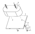
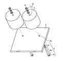
- FIG. FIG. 21 is a perspective view showing the heat generating component mounting device of the fifth embodiment
- FIG. 22 is an exploded perspective view showing the heat generating component mounting device of the fifth embodiment
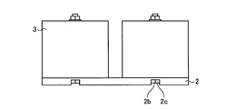
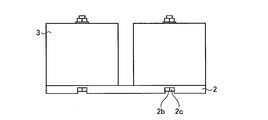
- FIG. 23 is a front view showing the heat generating component mounting device of the fifth embodiment.
- FIG. 24 and 25 are perspective views of a base plate used in the heat generating component mounting apparatus according to the fifth embodiment.
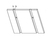
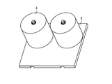
- the heat generating component mounting device has the same mounting structure as the heat generating component mounting device used in the first embodiment, and is characterized in that the heat generating component includes two mounting and fixing structures.
- the heat generating component mounting apparatus includes a base having two round through holes 1a for passing bolts, bolt head fixing grooves 1b for preventing rotation of bolt heads 4a, and bolt head storage spaces 1c.
- the plate 1 and the heat generating component 3 having two or more insertion holes 3a that are through spaces for passing the bolts 4 are formed. Further, the heat generating component 3 has an elliptical cross section.
- the reactor which is the heat generating component 3 used in the fifth embodiment, has a coil winding part as a core, a coil is wound, has an elliptical columnar outer shape, and the lead wire is led out from the side surface. Since other configurations are the same as those of the first embodiment, description thereof is omitted here. The same symbols are assigned to the same parts.
- the heat generating component mounting device of the fifth embodiment in addition to the effect of the heat generating component mounting device of the first embodiment, there is an effect that the posture of the heat generating component 3 can be more accurately fixed.
- the heat generating component 3 since the heat generating component 3 is fixed at two or more points, the heat generating component 3 does not rotate around the axis of the bolt 4 even when the heat generating component 3 is attached or the nut 5 is loosened, and the posture of the heat generating component 3 is accurate. It is effective in the structure that needs to be determined.
- the insertion hole 3a which is a space through which the bolt 4 passes, is not limited to a round shape, but is effective for an elliptical shape in which one side extends beyond the screw diameter of the bolt 4. Further, a flat plate may be sandwiched between the nut 5 and the heat generating component 3 and fixed.
- FIG. 26 is a perspective view showing a heat generating component mounting apparatus according to the sixth embodiment
- FIG. 27 is an exploded perspective view showing the heat generating component mounting apparatus according to the sixth embodiment
- FIG. 28 is a front view showing the heat generating component mounting apparatus according to the sixth embodiment.
- FIG. 29 and 30 are perspective views of a base plate used in the heat generating component mounting apparatus according to the sixth embodiment.
- the effect of the heat generating component mounting device of the sixth embodiment can accurately determine the posture of the heat generating component 3 in addition to the effect of the heat generating component mounting device of the second embodiment. That is, since the heat generating component mounting apparatus of the sixth embodiment fixes the heat generating component 3 at two or more points, the heat generating component 3 rotates around the axis of the bolt 4 even when the heat generating component 3 is attached or the nut 5 is loosened. This is effective in a structure in which the posture of the heat generating component 3 needs to be accurately determined.
- the heat generating component mounting device of the sixth embodiment is effective not only when the penetrating insertion hole 3a for passing the bolt 4 is a round shape but also an elliptical shape with one side extending beyond the screw diameter of the bolt 4. It is. Further, a flat plate may be sandwiched between the nut 5 and the heat generating component 3 and fixed.
- FIG. 31 is a perspective view showing a heat generating component mounting apparatus according to a seventh embodiment
- FIG. 32 is an exploded perspective view showing the heat generating component mounting apparatus according to the seventh embodiment
- FIG. 33 is a front view showing the heat generating component mounting apparatus according to the seventh embodiment.
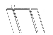
- FIG. 34 and 35 are perspective views of a base base used in the heat generating component mounting apparatus according to the seventh embodiment.
- the heat generating component mounting device is different from the heat generating component mounting device according to the third embodiment in that the round through hole 2a for passing the bolt 4 and the bolt head fixing groove 2b for preventing the bolt head 4a from rotating. And the base base 2 having two or more bolt head storage spaces 2c, and the heat generating component 3 having two or more insertion holes 3a through which the bolts 4 pass. Since others are the same as those of the third embodiment, description thereof is omitted here. The same symbols are assigned to the same parts.
- the heat generating component mounting device of the seventh embodiment has an effect that the posture of the heat generating component 3 can be determined more accurately. Since the heat generating component mounting apparatus of the seventh embodiment fixes the heat generating component 3 at two or more points, the heat generating component 3 may rotate around the axis of the bolt 4 even when the heat generating component 3 is mounted or the nut 5 is loosened. This is effective in a structure in which the posture of the heat generating component 3 needs to be determined accurately. Further, the through-hole 3a that penetrates the bolt 4 is effective not only in a round shape but also in an elliptical shape in which one side extends beyond the screw diameter of the bolt 4. Further, a flat plate may be sandwiched between the nut 5 and the heat generating component 3 and fixed.
- FIG. 36 is a perspective view showing the heat generating component mounting device of the eighth embodiment
- FIG. 37 is an exploded perspective view showing the heat generating component mounting device of the eighth embodiment
- FIG. 38 is a front view showing the heat generating component mounting device of the eighth embodiment.
- FIG. 39 and 40 are perspective views of a base base used in the heat generating component mounting apparatus according to the eighth embodiment.
- the heat generating component mounting device of the eighth embodiment is different from the heat generating component mounting device of the fourth embodiment in that a U-shaped through hole 2e for passing the bolt 4 and a bolt head fixing groove for preventing rotation of the bolt head 4a. 2b and a base base 2 having two or more bolt head storage spaces 2c, and a heat generating component 3 having two or more insertion holes 3a through which bolts 4 pass. . Since others are the same as those of the third embodiment, description thereof is omitted here. The same symbols are assigned to the same parts.
- the heat generating component mounting apparatus has an effect that the posture of the heat generating component 3 can be accurately determined in addition to the effect of the heat generating component mounting apparatus according to the fourth embodiment. Since the heat generating component mounting apparatus according to the eighth embodiment fixes the heat generating component 3 at two or more points, the heat generating component 3 may rotate around the axis of the bolt 4 even when the heat generating component 3 is mounted or when the nut 5 is loosened. This is effective in a structure in which the posture of the heat generating component 3 needs to be determined accurately. Further, the through-hole 3a that penetrates the bolt 4 is effective not only in a round shape but also in an elliptical shape in which one side extends beyond the screw diameter of the bolt 4. Further, a flat plate may be sandwiched between the nut 5 and the heat generating component 3 and fixed.
- FIG. 41 is a perspective view showing a heat generating component mounting device according to the ninth embodiment
- FIG. 42 is an exploded perspective view showing the heat generating component mounting device according to the ninth embodiment
- FIG. 43 is a front view showing the heat generating component mounting device according to the ninth embodiment.
- FIG. Further, the perspective view of the base plate used in the heat generating component mounting apparatus according to the ninth embodiment is the same as that shown in FIGS.
- the heat generating component mounting apparatus is used to prevent the base plate 1 from rotating the round through hole 1a through which the bolt 4 is passed and the bolt head 4a with respect to the heat generating component mounting apparatus according to the first embodiment.
- Two or more bolt head fixing grooves 1b and two bolt head storage spaces 1c are provided.
- the heat generating component 3 is different in that the heat generating component 3 has two insertion holes 3a through which the bolts 4 pass. Since others are the same as those of the first embodiment, description thereof is omitted here. The same symbols are assigned to the same parts.
- the heat generating component mounting device of the ninth embodiment is configured so that the heat generating components 3 to be placed on the base plate 1 have a quantity convenient for handling. Can be handled as a single unit, and the workability is excellent in a structure in which a plurality of heat generating components 3 are handled.
- FIG. 44 is a perspective view showing the heat generating component mounting device according to the tenth embodiment
- FIG. 45 is an exploded perspective view showing the heat generating component mounting device according to the tenth embodiment
- FIG. 46 is a front view showing the heat generating component mounting device according to the tenth embodiment.
- FIG. Further, the perspective view of the base plate used in the heat generating component mounting apparatus of the tenth embodiment is the same as that shown in FIGS.
- the base plate 1 prevents rotation of the U-shaped through hole 1e through which the bolt 4 passes and the bolt head 4a with respect to the heat generating component mounting apparatus according to the second embodiment.
- the heat generating component 3 is composed of two or more heat generating components 3 each having an insertion hole 3a through which the bolt 4 is passed. It is different in point. Since others are the same as those of the second embodiment, the description thereof is omitted here. The same symbols are assigned to the same parts.
- the heat generating component mounting device of the tenth embodiment has a base plate 1 having a heat generating component 3 placed on the base plate 1 in a convenient quantity for handling. Can be handled as a single unit, and the workability is excellent in a structure in which a plurality of heat generating components 3 are handled.
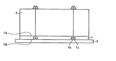
- FIG. 47 is a perspective view showing the heat generating component mounting device of the eleventh embodiment
- FIG. 48 is an exploded perspective view showing the heat generating component mounting device of the eleventh embodiment
- FIG. 49 is a front view showing the heat generating component mounting device of the eleventh embodiment.
- the perspective view of the base base used in the heat generating component mounting apparatus according to the eleventh embodiment is the same as that shown in FIGS.
- the base base 2 prevents the rotation of the round through hole 2a through which the bolt 4 passes and the bolt head 4a with respect to the heat generating component mounting apparatus according to the third embodiment.
- the heat generating component mounting device of the tenth embodiment has a base base base 2 by making the heat generating components 3 to be placed on the base base 2 convenient for handling. Since the table 2 can be handled as one unit, the structure that handles a plurality of heat generating components 3 is excellent in workability.
- FIG. FIG. 50 is a perspective view showing a heat generating component mounting device according to a twelfth embodiment
- FIG. 51 is an exploded perspective view showing the heat generating component mounting device according to the twelfth embodiment
- FIG. 52 is a front view showing the heat generating component mounting device according to the twelfth embodiment.
- FIG. Further, the perspective view of the base base used in the heat generating component mounting apparatus of the twelfth embodiment is the same as that shown in FIGS.
- the heat generating component mounting apparatus is different from the heat generating component mounting apparatus according to the fourth embodiment in that the base base 2 prevents the rotation of the U-shaped through hole 2e for passing the bolt 4 and the bolt head 4a.
- the base base 2 prevents the rotation of the U-shaped through hole 2e for passing the bolt 4 and the bolt head 4a.
- the heat generating component mounting device of the twelfth embodiment has a base base by making the heat generating components 3 to be placed on the base base 2 convenient for handling. Since the table 2 can be handled as one unit, the structure that handles a plurality of heat generating components 3 is excellent in workability.
- the heating component mounting apparatus has a structure in which the bolt head does not rotate on the surface opposite to the surface where the through hole through which the male screw of the bolt passes and the heavy heating component contacts. It has a board, a bolt for fixing a heavy heat generating component, a nut for screwing the bolt, and a heat generating component having a space through which a male screw of the bolt passes. Pass the bolt from the structure side where the bolt head of the base plate does not rotate, place the bolt head into the structure where the bolt head does not rotate, pass the mounting hole of the heat generating part through the male screw part of the protruding bolt, and Screw the male screw with the nut. A plain washer or a spring washer may be attached to the nut.
- the structure in which the bolt head does not rotate is not limited to the groove, and may be a recess including the groove.
- the base plate 1 and the base base 2 are made of an aluminum plate, and the bolt 4 and the nut 5 are made of stainless steel, but can be changed as appropriate.
- the base plate and the base base it is desirable to use a non-ferrous metal material having heat dissipation, such as an aluminum plate.
- Bolts and nuts are preferably made of ferrous metal, such as stainless steel, which has high breaking strength. About the material of the volt
- the reactor is used as the heat generating component.
- the present invention is not limited to the reactor, and any heat generating component having any weight is effective.
- the heat generating component mounting apparatus of the first to twelfth embodiments the following effects can be obtained. 1) Since the heavy heat generating component and the base plate are fixed by being sandwiched between the bolt head and nut, there is no screwing between the base plate and the bolt, and improper screwing or destruction of the screwing part due to large torque. Hard to occur. 2) Since the male screw of the bolt is screwed with a nut on the surface of the heavy heat-generating part on the operator side, the assembly operator can work while visually checking the screwing condition, so the screwing condition cannot be confirmed. Inappropriate screwing or destruction of the screwed part hardly occurs.
- the structure is such that the bolt protrudes from the base plate, and a heavy heat-generating component can be passed through the bolt, so that there is no need to hold the component with one hand during installation. Therefore, the workability is good, and when the screw is removed, the heavy heat-generating component is not easily dropped even if the screwing is unexpectedly removed.
Landscapes
- Engineering & Computer Science (AREA)
- General Engineering & Computer Science (AREA)
- Mechanical Engineering (AREA)
- Physics & Mathematics (AREA)
- Thermal Sciences (AREA)
- Microelectronics & Electronic Packaging (AREA)
- Cooling Or The Like Of Electrical Apparatus (AREA)
- Mounting Components In General For Electric Apparatus (AREA)
- Transformer Cooling (AREA)
Abstract
Ce dispositif de montage de composant thermogène comprend : un boulon 4 pourvu d'une partie filetée mâle 4c, d'une partie de corps principal de boulon 4b et d'une tête de boulon 4a ; un écrou 5 pourvu d'une partie filetée femelle 5c qui se visse avec la partie filetée mâle 4c ; un composant thermogène 3 comprenant un trou traversant 3a à travers lequel est inséré le boulon 4 ; et une plaque de base 1 qui présente une première surface principale 1A et une seconde surface principale 1B et qui est pourvue d'un trou traversant 1a qui permet à la partie filetée mâle 4c et à la partie de corps principal de boulon 4b du boulon 4 de passer à travers mais empêche la pénétration de la tête de boulon 4a, et d'une rainure de fixation de tête de boulon qui empêche la tête de boulon 4a de tourner. Le composant thermogène 3 est mis en contact avec la première surface principale 1A de la plaque de base 1 et fixé à celle-ci au moyen de l'écrou 5.
Priority Applications (2)
| Application Number | Priority Date | Filing Date | Title |
|---|---|---|---|
| PCT/JP2016/063087 WO2017187521A1 (fr) | 2016-04-26 | 2016-04-26 | Dispositif de montage de composant thermogène |
| JP2016558431A JP6242504B1 (ja) | 2016-04-26 | 2016-04-26 | 発熱部品取付け装置 |
Applications Claiming Priority (1)
| Application Number | Priority Date | Filing Date | Title |
|---|---|---|---|
| PCT/JP2016/063087 WO2017187521A1 (fr) | 2016-04-26 | 2016-04-26 | Dispositif de montage de composant thermogène |
Publications (1)
| Publication Number | Publication Date |
|---|---|
| WO2017187521A1 true WO2017187521A1 (fr) | 2017-11-02 |
Family
ID=60160312
Family Applications (1)
| Application Number | Title | Priority Date | Filing Date |
|---|---|---|---|
| PCT/JP2016/063087 Ceased WO2017187521A1 (fr) | 2016-04-26 | 2016-04-26 | Dispositif de montage de composant thermogène |
Country Status (2)
| Country | Link |
|---|---|
| JP (1) | JP6242504B1 (fr) |
| WO (1) | WO2017187521A1 (fr) |
Citations (5)
| Publication number | Priority date | Publication date | Assignee | Title |
|---|---|---|---|---|
| JPS60169827U (ja) * | 1984-04-18 | 1985-11-11 | 東北金属工業株式会社 | 大電流用チヨ−クコイルの絶縁ケ−ス |
| JPS63172120U (fr) * | 1987-04-30 | 1988-11-09 | ||
| JPH0189715U (fr) * | 1987-12-07 | 1989-06-13 | ||
| JP3037756U (ja) * | 1996-11-14 | 1997-05-20 | 友和産業株式会社 | ルーバー取付け具 |
| JP2009188033A (ja) * | 2008-02-04 | 2009-08-20 | Sumitomo Electric Ind Ltd | リアクトルの取付構造 |
-
2016
- 2016-04-26 WO PCT/JP2016/063087 patent/WO2017187521A1/fr not_active Ceased
- 2016-04-26 JP JP2016558431A patent/JP6242504B1/ja not_active Expired - Fee Related
Patent Citations (5)
| Publication number | Priority date | Publication date | Assignee | Title |
|---|---|---|---|---|
| JPS60169827U (ja) * | 1984-04-18 | 1985-11-11 | 東北金属工業株式会社 | 大電流用チヨ−クコイルの絶縁ケ−ス |
| JPS63172120U (fr) * | 1987-04-30 | 1988-11-09 | ||
| JPH0189715U (fr) * | 1987-12-07 | 1989-06-13 | ||
| JP3037756U (ja) * | 1996-11-14 | 1997-05-20 | 友和産業株式会社 | ルーバー取付け具 |
| JP2009188033A (ja) * | 2008-02-04 | 2009-08-20 | Sumitomo Electric Ind Ltd | リアクトルの取付構造 |
Also Published As
| Publication number | Publication date |
|---|---|
| JP6242504B1 (ja) | 2017-12-06 |
| JPWO2017187521A1 (ja) | 2018-05-17 |
Similar Documents
| Publication | Publication Date | Title |
|---|---|---|
| US4971497A (en) | Fastener system | |
| JP5200190B2 (ja) | 脱落防止具 | |
| JP5963359B2 (ja) | トランスユニット取付構造 | |
| US20150219144A1 (en) | Fastening device | |
| WO2016125378A1 (fr) | Structure d'attache pour dispositifs de bobine et dispositif de bobine | |
| US10770216B2 (en) | Reactor | |
| JP5193282B2 (ja) | 回り止め機構付きのボルトとナット | |
| KR101289572B1 (ko) | 조절가능한 풋 베어링 | |
| JP2017190793A (ja) | 脱落防止具 | |
| JP6242504B1 (ja) | 発熱部品取付け装置 | |
| JP5202821B2 (ja) | 巻上機の支持フレーム | |
| JP5784866B1 (ja) | センサ固定装置 | |
| US7394658B2 (en) | Heat sink with twist lock mounting mechanism | |
| BRPI0207388B1 (pt) | elemento de aterramento | |
| EP2425508B1 (fr) | Ensemble de raccordement et connexion d'une barre omnibus | |
| JP6307397B2 (ja) | 固定具 | |
| JP2008258363A (ja) | 係止装置 | |
| JP6573422B2 (ja) | 配線機器類の取着装置及び機器支持具 | |
| JP4986160B2 (ja) | ナット回転規制治具および変圧器解体器具 | |
| JP7655085B2 (ja) | 照明装置 | |
| JP5013612B2 (ja) | 機器取り付け用支持材 | |
| JP4967683B2 (ja) | エレベータ据付治工具用締結ピン | |
| JP2013239496A (ja) | 発熱体冷却用容器 | |
| TWI451835B (zh) | 散熱結構 | |
| JP7581956B2 (ja) | 照明装置 |
Legal Events
| Date | Code | Title | Description |
|---|---|---|---|
| ENP | Entry into the national phase |
Ref document number: 2016558431 Country of ref document: JP Kind code of ref document: A |
|
| NENP | Non-entry into the national phase |
Ref country code: DE |
|
| 121 | Ep: the epo has been informed by wipo that ep was designated in this application |
Ref document number: 16900394 Country of ref document: EP Kind code of ref document: A1 |
|
| 122 | Ep: pct application non-entry in european phase |
Ref document number: 16900394 Country of ref document: EP Kind code of ref document: A1 |