WO2017187528A1 - Outil de traitement d'énergie, système de traitement, et dispositif de commande - Google Patents
Outil de traitement d'énergie, système de traitement, et dispositif de commande Download PDFInfo
- Publication number
- WO2017187528A1 WO2017187528A1 PCT/JP2016/063095 JP2016063095W WO2017187528A1 WO 2017187528 A1 WO2017187528 A1 WO 2017187528A1 JP 2016063095 W JP2016063095 W JP 2016063095W WO 2017187528 A1 WO2017187528 A1 WO 2017187528A1
- Authority
- WO
- WIPO (PCT)
- Prior art keywords
- energy
- output
- treatment
- blood vessel
- blood pressure
- Prior art date
- Legal status (The legal status is an assumption and is not a legal conclusion. Google has not performed a legal analysis and makes no representation as to the accuracy of the status listed.)
- Ceased
Links
Images






Classifications
-
- A—HUMAN NECESSITIES
- A61—MEDICAL OR VETERINARY SCIENCE; HYGIENE
- A61B—DIAGNOSIS; SURGERY; IDENTIFICATION
- A61B18/00—Surgical instruments, devices or methods for transferring non-mechanical forms of energy to or from the body
- A61B18/04—Surgical instruments, devices or methods for transferring non-mechanical forms of energy to or from the body by heating
- A61B18/12—Surgical instruments, devices or methods for transferring non-mechanical forms of energy to or from the body by heating by passing a current through the tissue to be heated, e.g. high-frequency current
- A61B18/14—Probes or electrodes therefor
- A61B18/1442—Probes having pivoting end effectors, e.g. forceps
- A61B18/1445—Probes having pivoting end effectors, e.g. forceps at the distal end of a shaft, e.g. forceps or scissors at the end of a rigid rod
-
- A—HUMAN NECESSITIES
- A61—MEDICAL OR VETERINARY SCIENCE; HYGIENE
- A61B—DIAGNOSIS; SURGERY; IDENTIFICATION
- A61B17/00—Surgical instruments, devices or methods
- A61B17/32—Surgical cutting instruments
- A61B17/320068—Surgical cutting instruments using mechanical vibrations, e.g. ultrasonic
- A61B17/320092—Surgical cutting instruments using mechanical vibrations, e.g. ultrasonic with additional movable means for clamping or cutting tissue, e.g. with a pivoting jaw
-
- A—HUMAN NECESSITIES
- A61—MEDICAL OR VETERINARY SCIENCE; HYGIENE
- A61B—DIAGNOSIS; SURGERY; IDENTIFICATION
- A61B17/00—Surgical instruments, devices or methods
- A61B2017/00017—Electrical control of surgical instruments
- A61B2017/00022—Sensing or detecting at the treatment site
- A61B2017/00026—Conductivity or impedance, e.g. of tissue
-
- A—HUMAN NECESSITIES
- A61—MEDICAL OR VETERINARY SCIENCE; HYGIENE
- A61B—DIAGNOSIS; SURGERY; IDENTIFICATION
- A61B17/00—Surgical instruments, devices or methods
- A61B17/32—Surgical cutting instruments
- A61B17/320068—Surgical cutting instruments using mechanical vibrations, e.g. ultrasonic
- A61B17/320092—Surgical cutting instruments using mechanical vibrations, e.g. ultrasonic with additional movable means for clamping or cutting tissue, e.g. with a pivoting jaw
- A61B2017/320094—Surgical cutting instruments using mechanical vibrations, e.g. ultrasonic with additional movable means for clamping or cutting tissue, e.g. with a pivoting jaw additional movable means performing clamping operation
-
- A—HUMAN NECESSITIES
- A61—MEDICAL OR VETERINARY SCIENCE; HYGIENE
- A61B—DIAGNOSIS; SURGERY; IDENTIFICATION
- A61B17/00—Surgical instruments, devices or methods
- A61B17/32—Surgical cutting instruments
- A61B17/320068—Surgical cutting instruments using mechanical vibrations, e.g. ultrasonic
- A61B17/320092—Surgical cutting instruments using mechanical vibrations, e.g. ultrasonic with additional movable means for clamping or cutting tissue, e.g. with a pivoting jaw
- A61B2017/320095—Surgical cutting instruments using mechanical vibrations, e.g. ultrasonic with additional movable means for clamping or cutting tissue, e.g. with a pivoting jaw with sealing or cauterizing means
-
- A—HUMAN NECESSITIES
- A61—MEDICAL OR VETERINARY SCIENCE; HYGIENE
- A61B—DIAGNOSIS; SURGERY; IDENTIFICATION
- A61B18/00—Surgical instruments, devices or methods for transferring non-mechanical forms of energy to or from the body
- A61B2018/00005—Cooling or heating of the probe or tissue immediately surrounding the probe
- A61B2018/00041—Heating, e.g. defrosting
-
- A—HUMAN NECESSITIES
- A61—MEDICAL OR VETERINARY SCIENCE; HYGIENE
- A61B—DIAGNOSIS; SURGERY; IDENTIFICATION
- A61B18/00—Surgical instruments, devices or methods for transferring non-mechanical forms of energy to or from the body
- A61B2018/00315—Surgical instruments, devices or methods for transferring non-mechanical forms of energy to or from the body for treatment of particular body parts
- A61B2018/00345—Vascular system
- A61B2018/00404—Blood vessels other than those in or around the heart
-
- A—HUMAN NECESSITIES
- A61—MEDICAL OR VETERINARY SCIENCE; HYGIENE
- A61B—DIAGNOSIS; SURGERY; IDENTIFICATION
- A61B18/00—Surgical instruments, devices or methods for transferring non-mechanical forms of energy to or from the body
- A61B2018/00571—Surgical instruments, devices or methods for transferring non-mechanical forms of energy to or from the body for achieving a particular surgical effect
- A61B2018/00589—Coagulation
-
- A—HUMAN NECESSITIES
- A61—MEDICAL OR VETERINARY SCIENCE; HYGIENE
- A61B—DIAGNOSIS; SURGERY; IDENTIFICATION
- A61B18/00—Surgical instruments, devices or methods for transferring non-mechanical forms of energy to or from the body
- A61B2018/00571—Surgical instruments, devices or methods for transferring non-mechanical forms of energy to or from the body for achieving a particular surgical effect
- A61B2018/0063—Sealing
-
- A—HUMAN NECESSITIES
- A61—MEDICAL OR VETERINARY SCIENCE; HYGIENE
- A61B—DIAGNOSIS; SURGERY; IDENTIFICATION
- A61B18/00—Surgical instruments, devices or methods for transferring non-mechanical forms of energy to or from the body
- A61B2018/00636—Sensing and controlling the application of energy
- A61B2018/00696—Controlled or regulated parameters
- A61B2018/00702—Power or energy
-
- A—HUMAN NECESSITIES
- A61—MEDICAL OR VETERINARY SCIENCE; HYGIENE
- A61B—DIAGNOSIS; SURGERY; IDENTIFICATION
- A61B18/00—Surgical instruments, devices or methods for transferring non-mechanical forms of energy to or from the body
- A61B2018/00636—Sensing and controlling the application of energy
- A61B2018/00696—Controlled or regulated parameters
- A61B2018/00761—Duration
-
- A—HUMAN NECESSITIES
- A61—MEDICAL OR VETERINARY SCIENCE; HYGIENE
- A61B—DIAGNOSIS; SURGERY; IDENTIFICATION
- A61B18/00—Surgical instruments, devices or methods for transferring non-mechanical forms of energy to or from the body
- A61B2018/00636—Sensing and controlling the application of energy
- A61B2018/00773—Sensed parameters
- A61B2018/00827—Current
-
- A—HUMAN NECESSITIES
- A61—MEDICAL OR VETERINARY SCIENCE; HYGIENE
- A61B—DIAGNOSIS; SURGERY; IDENTIFICATION
- A61B18/00—Surgical instruments, devices or methods for transferring non-mechanical forms of energy to or from the body
- A61B2018/00636—Sensing and controlling the application of energy
- A61B2018/00773—Sensed parameters
- A61B2018/00875—Resistance or impedance
-
- A—HUMAN NECESSITIES
- A61—MEDICAL OR VETERINARY SCIENCE; HYGIENE
- A61B—DIAGNOSIS; SURGERY; IDENTIFICATION
- A61B18/00—Surgical instruments, devices or methods for transferring non-mechanical forms of energy to or from the body
- A61B2018/00636—Sensing and controlling the application of energy
- A61B2018/00773—Sensed parameters
- A61B2018/00892—Voltage
-
- A—HUMAN NECESSITIES
- A61—MEDICAL OR VETERINARY SCIENCE; HYGIENE
- A61B—DIAGNOSIS; SURGERY; IDENTIFICATION
- A61B18/00—Surgical instruments, devices or methods for transferring non-mechanical forms of energy to or from the body
- A61B2018/00994—Surgical instruments, devices or methods for transferring non-mechanical forms of energy to or from the body combining two or more different kinds of non-mechanical energy or combining one or more non-mechanical energies with ultrasound
-
- A—HUMAN NECESSITIES
- A61—MEDICAL OR VETERINARY SCIENCE; HYGIENE
- A61B—DIAGNOSIS; SURGERY; IDENTIFICATION
- A61B90/00—Instruments, implements or accessories specially adapted for surgery or diagnosis and not covered by any of the groups A61B1/00 - A61B50/00, e.g. for luxation treatment or for protecting wound edges
- A61B90/03—Automatic limiting or abutting means, e.g. for safety
- A61B2090/033—Abutting means, stops, e.g. abutting on tissue or skin
- A61B2090/034—Abutting means, stops, e.g. abutting on tissue or skin abutting on parts of the device itself
-
- A—HUMAN NECESSITIES
- A61—MEDICAL OR VETERINARY SCIENCE; HYGIENE
- A61B—DIAGNOSIS; SURGERY; IDENTIFICATION
- A61B90/00—Instruments, implements or accessories specially adapted for surgery or diagnosis and not covered by any of the groups A61B1/00 - A61B50/00, e.g. for luxation treatment or for protecting wound edges
- A61B90/06—Measuring instruments not otherwise provided for
- A61B2090/064—Measuring instruments not otherwise provided for for measuring force, pressure or mechanical tension
-
- A—HUMAN NECESSITIES
- A61—MEDICAL OR VETERINARY SCIENCE; HYGIENE
- A61B—DIAGNOSIS; SURGERY; IDENTIFICATION
- A61B90/00—Instruments, implements or accessories specially adapted for surgery or diagnosis and not covered by any of the groups A61B1/00 - A61B50/00, e.g. for luxation treatment or for protecting wound edges
- A61B90/06—Measuring instruments not otherwise provided for
- A61B2090/064—Measuring instruments not otherwise provided for for measuring force, pressure or mechanical tension
- A61B2090/065—Measuring instruments not otherwise provided for for measuring force, pressure or mechanical tension for measuring contact or contact pressure
-
- A—HUMAN NECESSITIES
- A61—MEDICAL OR VETERINARY SCIENCE; HYGIENE
- A61B—DIAGNOSIS; SURGERY; IDENTIFICATION
- A61B5/00—Measuring for diagnostic purposes; Identification of persons
- A61B5/02—Detecting, measuring or recording for evaluating the cardiovascular system, e.g. pulse, heart rate, blood pressure or blood flow
- A61B5/021—Measuring pressure in heart or blood vessels
- A61B5/022—Measuring pressure in heart or blood vessels by applying pressure to close blood vessels, e.g. against the skin; Ophthalmodynamometers
- A61B5/02233—Occluders specially adapted therefor
Definitions
- the present invention relates to an energy treatment tool for applying treatment energy to a treatment target held between a pair of gripping pieces, a treatment system including the energy treatment tool, and a control device used together with the energy treatment tool.
- a blood vessel When a treatment is performed using an energy treatment device such as International Publication No. 2012/061638, a blood vessel may be grasped as a treatment target between a pair of grasping pieces and the blood vessel may be sealed.
- a blood vessel with high blood pressure may be grasped, and treatment energy such as high-frequency current may be applied to the grasped blood vessel.
- treatment energy such as high-frequency current
- the blood pressure of the grasped blood vessel increases, the treatment for sealing the blood vessel using treatment energy may be affected. Thereby, there is a possibility of affecting the sealing performance of the blood vessel such as the pressure resistance value (difficulty of blood flow) of the sealed blood vessel.
- the present invention has been made to solve the above-described problems, and an object of the present invention is to provide an energy treatment device, a treatment system, and a control that can exhibit appropriate treatment performance even when a blood vessel with high blood pressure is sealed. To provide an apparatus.
- an energy treatment device opens and closes between a first gripping piece and the first gripping piece, and a blood vessel is formed between the first gripping piece. And a second mode different from the first mode for coagulating the blood vessel according to the blood pressure of the blood vessel, and a second mode different from the first mode for coagulating the blood vessel. The operating state is switched between.
- Another aspect of the present invention includes: a second gripping piece that opens and closes between the first gripping piece and the first gripping piece, and grips a blood vessel between the first gripping piece;
- a control device used together with an energy treatment tool comprising: outputting electrical energy supplied to the energy treatment tool; and supplying the electric energy to the energy treatment tool; and
- An energy output source for applying treatment energy to the blood vessel grasped between the second grasping piece and a processor for obtaining blood pressure at a site related to the grasped blood vessel, Based on controlling the output of the electrical energy from the energy output source, and if the acquired blood pressure is greater than or equal to a blood pressure threshold, is the blood pressure lower than the blood pressure threshold?
- a processor for performing at least one of increasing the gripping force of the blood vessels between the second gripping piece and said first gripping piece as compared to if.
- FIG. 1 is a schematic view showing a treatment system according to the first embodiment.
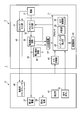
- FIG. 2 is a block diagram illustrating a control configuration in the treatment system according to the first embodiment.
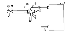
- FIG. 3 is a schematic diagram illustrating a measurement unit according to an example of the first embodiment.
- FIG. 4 is a schematic diagram illustrating a measurement unit according to another example of the first embodiment.
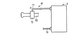
- FIG. 5 is a schematic diagram illustrating a measurement unit according to still another embodiment of the first embodiment.
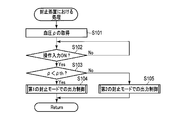
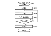
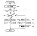
- FIG. 6 is a flowchart showing processing in the processor in the blood vessel sealing treatment using the treatment system according to the first embodiment.
- FIG. 7 is a flowchart illustrating processing in output control in the first sealing mode of the processor according to the first embodiment.
- FIG. 1 is a schematic view showing a treatment system according to the first embodiment.
- FIG. 2 is a block diagram illustrating a control configuration in the treatment system according to the first embodiment.
- FIG. 3 is a schematic diagram illustrating a measurement unit according to an example of the first
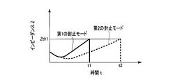
- FIG. 8 shows the time-dependent impedance between a pair of gripping pieces in a state where the processor according to the first embodiment performs output control in each of the first sealing mode and the second sealing mode. It is a schematic diagram showing an example of various changes.
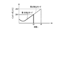
- FIG. 9 illustrates a pair of gripping pieces in a state where the processor according to the first modification of the first embodiment performs output control in each of the first sealing mode and the second sealing mode. It is the schematic which shows an example of a time-dependent change of the impedance between.
- FIG. 10 is a flowchart illustrating processing in output control in the second sealing mode of the processor according to the second modification of the first embodiment.
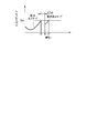
- FIG. 11 illustrates a pair of gripping pieces in a state where the processor according to the second modification of the first embodiment performs output control in each of the first sealing mode and the second sealing mode. It is the schematic which shows an example of a time-dependent change of the impedance between.
- FIG. 12 is a flowchart illustrating processing in output control in the second sealing mode of the processor according to the third modification of the first embodiment.
- FIG. 13 is a flowchart showing processing in the processor in the blood vessel sealing treatment using the treatment system according to the fourth modification of the first embodiment.
- FIG. 14 is a block diagram illustrating a control configuration in the treatment system according to the second embodiment.
- FIG. 15 is a schematic diagram illustrating an example of a gripping force adjusting element according to the second embodiment.
- FIG. 16 is a flowchart showing processing in a processor in a blood vessel sealing treatment using the treatment system according to the second embodiment.
- FIG. 1 is a diagram showing a treatment system 1 of the present embodiment.
- the treatment system 1 includes an energy treatment tool 2 and a control device (energy control device) 3.
- the energy treatment device 2 has a longitudinal axis C.
- one side in the direction along the longitudinal axis C is defined as the distal end side (arrow C1 side), and the opposite side to the distal end side is defined as the proximal end side (arrow C2 side).
- the energy treatment device 2 includes a holdable housing 5, a sheath (shaft) 6 connected to the distal end side of the housing 5, and an end effector 7 provided at the distal end portion of the sheath 6.
- One end of a cable 10 is connected to the housing 5 of the energy treatment device 2.
- the other end of the cable 10 is detachably connected to the control device 3.
- the housing 5 is provided with a grip (fixed handle) 11, and a handle (movable handle) 12 is rotatably attached. When the handle 12 is rotated with respect to the housing 5, the handle 12 is opened or closed with respect to the grip 11.
- the handle 12 is positioned on the distal end side with respect to the grip 11, and moves substantially parallel to the longitudinal axis C in the opening or closing operation with respect to the grip 11, but this is not restrictive. Absent.
- the handle 12 may be located proximal to the grip 11.
- the handle 12 is located on the side opposite to the grip 11 with respect to the longitudinal axis C, and the moving direction in the opening or closing operation with respect to the grip 11 intersects with the longitudinal axis C. (It may be substantially vertical).
- the sheath 6 extends along the longitudinal axis C.
- the end effector 7 includes a first gripping piece 15 and a second gripping piece 16 that opens and closes between the first gripping piece 15.
- the handle 12 and the end effector 7 are connected via a movable member 17 extending along the longitudinal axis C inside the sheath 6.
- the handle 12 By opening or closing the handle 12, which is an opening / closing operation input unit, with respect to the grip 11, the movable member 17 moves along the longitudinal axis C with respect to the sheath 6 and the housing 5, and between the pair of gripping pieces 15, 16. Opens or closes.
- a biological tissue such as a blood vessel is held as a treatment target between the gripping pieces 15 and 16.
- the opening / closing directions (directions of arrows Y1 and Y2) of the gripping pieces 15 and 16 intersect with the longitudinal axis C (substantially perpendicular).
- the end effector 7 may be configured to open or close between the pair of gripping pieces 15 and 16 corresponding to the opening operation and the closing operation of the handle 12, respectively.
- one of the gripping pieces 15, 16 is integral with the sheath 6 or fixed to the sheath 6, and the other of the gripping pieces 15, 16 is pivoted to the distal end portion of the sheath 6. Mounted as possible.
- both gripping pieces 15, 16 are pivotally attached to the distal end of the sheath 6.
- a rod member (not shown) is inserted into the sheath 6, and one of the grip pieces 15, 16 is formed by a protruding portion of the rod member (probe) from the sheath 6 toward the distal end side. .
- the other of the gripping pieces 15 and 16 is attached to the distal end portion of the sheath 6 so as to be rotatable.
- a rotation operation knob (not shown) may be attached to the housing 5.
- the sheath 6 and the end effector 7 rotate about the longitudinal axis C with respect to the housing 5 together with the rotary operation knob.
- the angular position about the longitudinal axis C of the end effector 7 is adjusted.
- FIG. 2 is a diagram showing a control configuration in the treatment system 1.
- the control device 3 includes a processor (control unit) 21 that controls the entire treatment system 1 and a storage medium 22.
- the processor 21 is formed of an integrated circuit including a CPU (Central Processing Unit), an ASIC (Application Specific Integrated Circuit), or an FPGA (Field Programmable Gate Array).
- the processor 21 may be formed from one integrated circuit or may be formed from a plurality of integrated circuits. Processing in the processor 21 is performed according to a program stored in the processor 21 or the storage medium 22.
- the storage medium 22 stores a processing program used by the processor 21, parameters and tables used for calculation by the processor 21, and the like.
- the processor 21 includes an impedance detection unit 23, a determination unit 25, and an output control unit 26.
- the impedance detection unit 23, the determination unit 25, and the output control unit 26 function as part of the processor 21 and perform part of the processing performed by the processor 21.
- the control device 3 includes a power source 31 that is a battery or an outlet, and an energy output source (first energy output source) 32.
- the energy output source 32 is electrically connected to the electrodes 27 and 28 via an electric supply path (first electric supply path) 33 extending through the inside of the cable 10.
- the energy output source 32 includes a conversion circuit, an amplifier circuit, and the like, and converts electric power from the power supply 31.
- the energy output source 32 outputs the converted electric energy (high frequency power).
- the electric energy output from the energy output source 32 is supplied to the electrodes 27 and 28 through the electric supply path 33.
- the output control unit 26 of the processor 21 controls driving of the energy output source 32 and controls the output of electric energy from the energy output source 32. As a result, any one of the output power P, the output current I, and the output voltage V from the energy output source 32 is adjusted, and the supply of electrical energy to the electrodes 27 and 28 is controlled.
- the treatment target gripped while being in contact with the electrodes 27 and 28 is passed through.
- a high frequency current flows between the electrodes 27 and 28. That is, a high-frequency current is applied to the treatment target as treatment energy.
- the high frequency current flows through the treatment target, heat is generated in the treatment target, and the treatment target is denatured by the heat. Thereby, the treatment target such as a blood vessel is sealed (coagulated) using the high-frequency current.
- the grasping pieces 15 and 16 serve as an energy application unit that applies a high-frequency current as treatment energy to the treatment target (blood vessel) to be grasped.
- a current detection circuit 35 and a voltage detection circuit 36 are provided in the electricity supply path 33.
- the current detection circuit 35 detects the output current I
- the voltage detection circuit 36 detects the output voltage V.
- the energy control device 3 is provided with an A / D converter 37.
- An analog signal related to the current I detected by the current detection circuit 35 and an analog signal related to the voltage V detected by the voltage detection circuit 36 are transmitted to the A / D converter 37.
- the A / D converter 37 converts the analog signal related to the current I and the analog signal related to the voltage V into a digital signal, and transmits the converted digital signal to the processor 21.
- the processor 21 acquires information on the output current I and the output voltage V from the energy output source 32.
- the impedance detection unit 23 of the processor 21 detects the impedance of the electric supply path 33 including the treatment target (blood vessel) to be grasped and the electrodes 27 and 28 based on the output current I and the output voltage V. Thereby, the impedance Z (that is, the impedance of the treatment target to be grasped) between the pair of grasping pieces 15 and 16 is detected.
- an operation button 18 is attached to the housing 5 as an energy operation input unit.
- an operation for outputting electric energy from the energy output source 32 to the energy treatment device 2 is input to the control device 3.
- a foot switch or the like separate from the energy treatment device 2 may be provided as the energy operation input unit.
- the processor 21 detects the presence / absence of an operation input at an energy operation input unit such as the operation button 18.
- the output control unit 26 of the processor 21 controls the output of electrical energy from the energy output source 32 based on the operation input from the operation button 18.
- the treatment system 1 is provided with a measurement unit (measuring instrument) 41.
- the measurement unit 41 measures the blood pressure ⁇ at a site related to a blood vessel gripped between the gripping pieces 15 and 16 as a treatment target.
- the measurement unit 41 may be provided in the energy treatment device 2 or may be provided separately from the energy treatment device 2.
- FIG. 3 shows a measurement unit 41 in one embodiment
- FIG. 4 shows a measurement unit 41 in another example.
- FIG. 5 shows a measurement unit 41 in still another embodiment.
- the measurement unit (measurement device) 41 includes a measurement forceps 60 that is provided separately from the energy treatment instrument 2.
- the measurement forceps 60 includes a pair of gripping pieces 61 and 62 and a damper 63.
- a pressure sensor 65 is provided on one of the grip pieces 61 and 62 (for example, the grip piece 62).
- the measuring forceps 60 grips the arterial blood vessel between the gripping pieces 61 and 62, and measures the blood pressure ⁇ in the arterial blood vessel gripped by a so-called oscillometric method.
- the arterial blood vessel to be grasped is compressed by closing between the grasping pieces 61 and 62 to close the arterial blood vessel. . Then, the compression (occlusion) of the grasped arterial blood vessel is gradually released using the damper 63 or the like, and the pressure in the arterial blood vessel between the grasping pieces 61 and 62 is gradually reduced. In a state where the pressure in the grasped arterial blood vessel is gradually reduced, the pressure sensor 65 is used to detect the pressure pulse wave of the grasped arterial blood vessel.
- the measurement unit 41 detects the average blood pressure ⁇ ave of the arterial blood vessel between the gripping pieces 61 and 62 based on the maximum blood pressure ⁇ max and the minimum blood pressure ⁇ min, and measures the average blood pressure ⁇ ave as the blood pressure ⁇ of the arterial blood vessel.
- the blood pressure ⁇ can be measured only in the arterial blood vessels, and the blood pressure in the venous blood vessels cannot be measured. For this reason, when an arterial blood vessel is grasped as a treatment target between the grasping pieces 15 and 16 of the energy treatment device 2 (when an arterial blood vessel sealing treatment is performed), the arterial blood vessel to be sealed (treatment) The blood pressure ⁇ of the subject) is measured, and the measured blood pressure ⁇ is used as the blood pressure ⁇ at the site related to the blood vessel (arterial blood vessel) to be sealed.
- the venous blood vessel to be sealed (treatment object)
- the measured blood pressure ⁇ is used as the blood pressure ⁇ at the site related to the blood vessel (venous blood vessel) to be sealed.
- the blood pressure of the venous blood vessel has a magnitude corresponding to the blood pressure of the related arterial blood vessel. Therefore, even when a venous blood vessel is treated as a treatment target, the magnitude of the blood pressure of the venous blood vessel that is the treatment target can be determined based on the blood pressure ⁇ in the related arterial blood vessel.
- the measurement unit 41 includes a pressure sensor 67 provided on one of the gripping pieces 15 and 16 of the energy treatment instrument 2 (for example, the gripping piece 16).
- the arterial blood vessel X1 is grasped between the grasping pieces 15 and 16, and the blood pressure ⁇ in the arterial blood vessel X1 grasped by the so-called trimetry method is measured. That is, when measuring the blood pressure ⁇ of the arterial blood vessel X1 between the gripping pieces 15 and 16, the gripping pieces 15 and 16 are compressed on the outer surface of the arterial blood vessel X1 by closing the gripping pieces 15 and 16.
- the arterial blood vessel X1 is gripped in a state in which the parts Q1 and Q2 that are in contact with the gripping pieces 15 and 16 are flat.
- the pressure sensor 67 is brought into contact with a flat portion (eg, Q2) on the outer surface of the grasped arterial blood vessel X1, and the blood pressure ⁇ of the grasped arterial blood vessel X1 is measured using the pressure sensor 67.
- a flat portion eg, Q2
- the blood pressure ⁇ can be measured only in the arterial blood vessels, and the blood pressure in the venous blood vessels cannot be measured. For this reason, when an arterial blood vessel is grasped as a treatment target between the grasping pieces 15 and 16 of the energy treatment device 2 (when an arterial blood vessel sealing treatment is performed), the arterial blood vessel to be sealed (treatment) The blood pressure ⁇ of the subject is measured, and when the venous blood vessel is grasped as a treatment target between the grasping pieces 15 and 16 (when the venous blood vessel is sealed), the venous blood vessel to be sealed ( The blood pressure ⁇ of the arterial blood vessel related to the treatment target) is measured.
- the lock member (not shown) that locks the handle 12 in a state where the portions Q1 and Q2 pressed by the gripping pieces 15 and 16 on the outer surface of the arterial blood vessel X1 to be gripped is flat is energy.
- the treatment tool 2 may be provided.
- the operation of the locking member is controlled by the processor 21.
- the processor 21 releases the lock of the handle 12 by the lock member based on the operation input performed by the operation button 18 (that is, the operation input is switched from OFF to ON).
- the region between the grip pieces 15 and 16 is further closed from the state where the portions Q1 and Q2 pressed by the grip pieces 15 and 16 in the treatment target become flat, and treatment energy such as high-frequency current is applied to the treatment target. .
- the measuring unit (measuring instrument) 41 includes a blood pressure measuring instrument 71 used for physical examination or the like.
- the cuff 72 of the blood pressure measuring device 71 is wound around the upper arm of one arm X2, and the blood pressure ⁇ of the aorta at a position immediately after blood flows out from the left ventricle through the aortic valve is measured. Then, the measured blood pressure ⁇ is used as the blood pressure ⁇ at a site related to the blood vessel to be sealed.
- each blood pressure in the blood vessel has a magnitude corresponding to the measured blood pressure ⁇ of the aorta. For this reason, the magnitude of the blood pressure of the blood vessel to be treated can be determined based on the blood pressure ⁇ at the site immediately after blood flows out of the left ventricle in the aorta.
- the measurement unit 41 measures the blood pressure ⁇ at a site related to a blood vessel (blood vessel to be sealed) grasped between the grasping pieces 15 and 16 as a treatment target. To do. Then, the blood pressure of the blood vessel to be treated has a magnitude corresponding to the measured blood pressure ⁇ .
- the energy control device 3 is provided with an A / D converter 45.
- An analog signal indicating the blood pressure ⁇ measured by the measurement unit 41 is transmitted to the A / D converter 45.
- the A / D converter 45 converts an analog signal indicating the blood pressure ⁇ into a digital signal, and transmits the converted digital signal to the processor 21.
- the A / D converter 45 may be provided in the measurement unit 41. In this case, an analog signal indicating the measurement result of the blood pressure ⁇ is converted into a digital signal by the measurement unit 41, and the converted digital signal is transmitted from the measurement unit 41 to the processor 21.
- the determination unit 25 of the processor 21 determines whether or not the measured blood pressure ⁇ is lower than the blood pressure threshold (threshold value) ⁇ th based on the measurement result of the blood pressure ⁇ in the measurement unit 41.
- the blood pressure threshold ⁇ th is, for example, 130 mmHg.
- the blood pressure threshold ⁇ th may be set by an operator or the like, or may be stored in the storage medium 22.
- the output control unit 26 of the processor 21 controls the output of electric energy from the energy output source 32 based on the measurement result in the measurement unit 41 and the determination result on the blood pressure ⁇ .
- the operating state of the energy treatment device 2 is between the first mode (first operating mode) and the second mode (second operating mode). Switch with.
- the application state of the treatment energy (high-frequency current) to the treatment object grasped from the energy application unit (gripping pieces 15 and 16) is different from each other. Different.
- the ultrasonic transducer 46 may be provided in the energy treatment device 2 (inside the housing 5).
- the rod member is connected to the distal end side of the ultrasonic transducer 46, and one of the gripping pieces 15 and 16 (for example, the first gripping piece 15) is formed by the protruding portion of the rod member from the sheath 6 toward the distal end side.
- the control device 3 is provided with an energy output source (second energy output source) 47 in addition to the energy output source 32.
- the energy output source 47 is electrically connected to the ultrasonic transducer 46 via an electric supply path (second electric supply path) 48 extending through the inside of the cable 10.
- the energy output source 47 may be integrated with the energy output source 32 or may be formed separately from the energy output source 32.
- the energy output source 47 includes a conversion circuit, an amplifier circuit, and the like, and converts power from the power source 31.
- the energy output source 47 outputs the converted electric energy (AC power).
- the electric energy output from the energy output source 47 is supplied to the ultrasonic transducer 46 through the electric supply path 48.
- the output control unit 26 of the processor 21 controls driving of the energy output source 47 and controls the output of electric energy from the energy output source 47.
- the ultrasonic transducer 46 when the electrical energy (AC power) output from the energy output source 47 is supplied to the ultrasonic transducer 46, ultrasonic vibration is generated in the ultrasonic transducer 46.
- the generated ultrasonic vibration is transmitted from the proximal end side to the distal end side in the rod member (vibration transmitting member), so that the rod member including one of the gripping pieces 15 and 16 (for example, the first gripping piece 15) vibrates.
- the rod member vibrates while the treatment target is gripped between the gripping pieces 15 and 16
- ultrasonic vibration is applied to the treatment target as treatment energy.
- frictional heat due to vibration is generated, and it is possible to make an incision while sealing (coagulating) a treatment target such as a blood vessel by the frictional heat.
- a heater may be provided in the end effector 7 (at least one of the gripping pieces 15 and 16) instead of the ultrasonic transducer 46.
- the electric energy (DC power or AC power) output from the energy output source (47) is supplied to the heater through the electric supply path (48). Accordingly, heat is generated by the heater, and it is possible to make an incision while sealing (coagulating) a treatment target such as a blood vessel by the heat generated by the heater.
- at least one of the grasping pieces 15 and 16 functions as an energy application unit that applies treatment energy to the treatment target. To do.
- the operator holds the housing 5 of the energy treatment device 2 and inserts the end effector 7 into a body cavity such as the abdominal cavity. Then, a blood vessel (treatment target) is disposed between the gripping pieces 15 and 16, and the handle 12 is closed with respect to the grip 11 to close the space between the gripping pieces 15 and 16. Thereby, the blood vessel is grasped between the grasping pieces 15 and 16.
- the blood pressure ⁇ at a site related to the grasped blood vessel is measured using the measurement unit 41. Then, for example, a high-frequency current is applied to the blood vessel as treatment energy, and the blood vessel to be grasped is sealed. The blood pressure ⁇ is measured before an operation for applying treatment energy to the blood vessel (an operation for outputting electric energy from the energy output source 32) is input with the operation button 18.
- FIG. 6 is a flowchart showing the processing in the processor 21 in the blood vessel sealing treatment using the treatment system 1 of the present embodiment.
- the processor 21 acquires a blood pressure ⁇ at a site related to the grasped blood vessel (step S101). That is, the measurement result in the measurement unit 41 is acquired.
- the processor 21 determines whether or not an operation input with the operation button (energy operation input unit) 18 has been performed (that is, whether the operation input is ON or OFF) (step S102). If no operation input has been made (step S102-No), the process returns to step S102. That is, the processor 21 stands by until an operation input is performed with the operation button 18.
- the determination unit 25 of the processor 21 determines whether or not the acquired blood pressure ⁇ is lower than the blood pressure threshold (threshold) ⁇ th (step S103). That is, it is determined whether or not the blood pressure ⁇ is equal to or greater than the blood pressure threshold ⁇ th.
- the output control unit 26 of the processor 21 performs output control of electric energy from the energy output source 32 in the first sealing mode.
- the processor 21 may perform a process of determining (setting) that the blood pressure of the blood vessel gripped between the gripping pieces 15 and 16 is low.
- the output control unit 26 determines the electrical energy from the energy output source 32 in the second sealing mode different from the first sealing mode. Output control is performed (step S105).
- FIG. 7 is a flowchart showing the processing of the processor 21 in the output control in the first sealing mode.
- the processor 21 starts outputting electric energy (high-frequency power) from the energy output source (first energy output source) 32 (step). S111).
- electric energy is supplied to the electrodes 27 and 28, a high-frequency current flows through the grasped blood vessel, and the blood vessel is sealed.
- Step S112 When a certain amount of time has elapsed from the start of the output of electrical energy from the energy output source 32, the output control unit 26 performs constant voltage control that keeps the output voltage V from the energy output source 32 constant over time at the first voltage value V1.
- the impedance detector 23 of the processor 21 detects the output current I detected by the current detector 35 and the output voltage V detected by the voltage detector 36. Based on the result, the impedance Z (that is, the impedance of the treatment target to be grasped) between the grasping pieces 15 and 16 is detected (step S113).
- the processor 21 determines whether or not the detected impedance Z is equal to or greater than the impedance threshold (first impedance threshold) Zth1 (step S114).
- the impedance threshold value Zth1 may be set by an operator or the like, or may be stored in the storage medium 22.
- step S114-No If the impedance Z is smaller than the impedance threshold Zth1 (step S114-No), the process returns to step S112, and the processes after step S112 are sequentially performed.
- the output control unit 26 stops the output of electric energy (high frequency power) from the energy output source 32 (step S115). Thereby, the supply of electrical energy to the electrodes 27 and 28 is stopped.
- the processor 21 performs output control of the electrical energy from the energy output source 32 in the first sealing mode, the energy treatment tool 2 coagulates the treatment target to be grasped (seals the blood vessel). Operated in mode.
- the processor 21 performs the processes of steps S111 and S113 to S115.
- the output control unit 26 reduces the output voltage V from the energy output source 32 to be smaller than the first voltage value V1. Constant voltage control is performed to keep the second voltage value V2 constant over time. Since constant voltage control is performed with the second voltage value V2 that is smaller than the first voltage value V1, the electric power output from the energy output source 32 is higher in the second sealing mode than in the first sealing mode. Energy is small.
- the output control unit 26 of the processor 21 reduces the electric energy output from the energy output source 32 in the second sealing mode as compared with the first sealing mode.
- the processor 21 performs output control of the electrical energy from the energy output source 32 in the second sealing mode
- the energy treatment tool 2 coagulates the treatment target to be grasped (seals the blood vessel), and And operated in a second mode different from the first mode.
- the processor 21 controls the first mode (first operation mode) by controlling the output of the electrical energy from the energy output source 32 based on the determination result of the blood pressure ⁇ .
- the operation state of the energy treatment device 2 is switched between the second mode (second operation mode).
- the energy treatment instrument 2 Since the output state of electrical energy from the energy output source 32 is different between the first sealing mode and the second sealing mode, the energy treatment instrument 2 has a difference between the first mode and the second mode. In the meantime, the application state of treatment energy (high-frequency current) to the treatment object grasped from the energy application unit (gripping pieces 15 and 16) is different from each other.
- Output control may be performed other than the control.
- the output control unit 26 performs constant power control that keeps the output power P from the energy output source 32 constant over time at the first power P1.
- the output control unit 26 performs constant power control that keeps the output power P from the energy output source 32 constant over time with the second power P2 that is smaller than the first power P1.
- the output voltage V is kept constant at the first voltage value V1 over time, and the output power P is set to the first power P1.
- the output voltage V is kept constant at a second voltage value V2 that is smaller than the first voltage value V1, and the output power P is set to the first power P1. It is possible to perform both constant power control that is kept constant over time with the smaller second power P2, and the constant voltage control and the constant power control are switched according to the impedance Z.
- the electrical energy output from the energy output source 32 is smaller in the second sealing mode than in the first sealing mode.
- the processor 21 transmits the energy output source 47 to the ultrasonic transducer 46 in each of the first sealing mode and the second sealing mode. Stop the output of electrical energy. For this reason, in each of the first sealing mode and the second sealing mode, no electrical energy is supplied to the ultrasonic transducer 46 and no ultrasonic vibration is generated in the ultrasonic transducer 46.
- the processor 21 stops the output of electric energy from the energy output source to the heater in each of the first sealing mode and the second sealing mode. To do. For this reason, in each of the first sealing mode and the second sealing mode, electric energy is not supplied to the heater, and no heat is generated in the heater.
- the process automatically shifts to the output control to the incision mode.
- the processor 21 outputs electric energy from the energy output source 47 to the ultrasonic transducer 46 at the incision level (high output level).
- ultrasonic vibration is generated by the ultrasonic transducer 46, and the ultrasonic vibration is transmitted to one of the gripping pieces 15 and 16. Then, the transmitted ultrasonic vibration is applied to a blood vessel (treatment target) to be grasped as treatment energy, and the blood vessel is incised by frictional heat due to the ultrasonic vibration.
- the processor 21 outputs electric energy from the energy output source to the heater at the cutting level (high output level). Thereby, heat is generated by the heater. Then, heater heat is applied to the blood vessel to be grasped as treatment energy, and the blood vessel is incised.
- FIG. 8 shows the impedance Z between the pair of gripping pieces 15 and 16 (that is, the gripped state) when the processor 21 performs output control in each of the first sealing mode and the second sealing mode. It is a figure which shows an example of a time-dependent change of the impedance of the treatment object.
- the vertical axis represents impedance Z
- the horizontal axis represents time t based on the start of output of electrical energy from the energy output source 32.
- the change with time in the impedance Z in the first sealing mode is indicated by a solid line
- the change with time in the impedance Z in the second sealing mode is indicated by a broken line. As shown in FIG.
- the behavior that the impedance Z decreases with time for a while. Indicates.
- the impedance Z decreases with time to some extent, the impedance Z usually exhibits a behavior of increasing with time in response to the temperature of the treatment target rising due to heat caused by the high-frequency current.
- the electrical energy output from the energy output source 32 is smaller in the second sealing mode than in the first sealing mode.
- the amount of heat per unit time generated due to the high-frequency current flowing in the blood vessel (treatment target) is smaller than that in the first sealing mode. Therefore, in the second sealing mode, the rate of increase in the temperature of the treatment target (blood vessel) is small in comparison with the first sealing mode, and the rate of increase in impedance Z in a state where the impedance Z increases with time is small. .
- the time from the start of the output of electric energy from the energy output source 32 until the impedance Z reaches the impedance threshold value Zth1 is longer than in the first sealing mode.
- the impedance Z in the first sealing mode, the impedance Z reaches the impedance threshold Zth1 at time t1, whereas in the second sealing mode, the impedance Z is at time t2 after time t1.
- the impedance threshold Zth1 is reached.
- the electric energy from the energy output source 32 in each of the first sealing mode and the second sealing mode, the electric energy from the energy output source 32 is based on the fact that the impedance Z is equal to or higher than the impedance threshold Zth1. Output is stopped. Therefore, the output time of electric energy from the energy output source 32 is longer in the second sealing mode than in the first sealing mode.
- the output control unit 26 reduces the electric energy output from the energy output source 32, and the energy output source.
- the output time of the electric energy from 32 is lengthened. For this reason, in the second sealing mode, compared with the first sealing mode, the amount of heat per unit time generated due to the high-frequency current in the blood vessel is small, and the time during which the high-frequency current is applied to the blood vessel is long. That is, in the energy treatment instrument 2, the treatment target (blood vessel) is transferred from the energy application unit (gripping pieces 15 and 16) in the second mode (second operation mode) as compared to the first mode (first operation mode). The treatment energy (high-frequency current) is applied for a long time.
- the total amount of treatment energy (high-frequency current) applied to the treatment target in the first sealing mode corresponds to, for example, the size of the area between the impedance Z and the time t indicated by the solid line in FIG. To do.
- the total amount of treatment energy (high-frequency current) applied to the treatment target in the second sealing mode is, for example, the size of the area between the impedance Z and time t indicated by the broken line in FIG.
- the area under the impedance Z in the second sealing mode indicated by the broken line is larger than the area under the impedance Z in the first sealing mode indicated by the solid line. Therefore, in the second sealing mode, the blood vessel sealing performance by high-frequency current is higher than that in the first sealing mode.
- a blood vessel with high blood pressure may be grasped between the grasping pieces 15 and 16, and treatment energy such as high-frequency current may be applied to the grasped blood vessel.
- treatment energy such as high-frequency current
- the blood pressure of the grasped blood vessel becomes high, there is a possibility of affecting the treatment sealed using treatment energy such as high-frequency current. For this reason, there is a possibility of affecting the sealing performance of the blood vessel such as the pressure resistance value of the sealed blood vessel.
- the measurement unit 41 measures the blood pressure ⁇ at a site related to the blood vessel (sealed blood vessel) gripped between the gripping pieces 15 and 16, and based on the measurement result of the measurement unit 41.
- the processor 21 controls the output of electrical energy from the energy output source 32 or the like.
- the blood pressure ⁇ is lower than the blood pressure threshold (threshold) ⁇ th
- output control is performed in the first sealing mode.
- the blood pressure ⁇ is equal to or higher than the blood pressure threshold ⁇ th
- output control is performed in the second sealing mode. Is done.
- the electrical energy output from the energy output source 32 is smaller than when the blood pressure ⁇ is lower than the blood pressure threshold ⁇ th, and the electric power from the energy output source 32 is Energy output time is long. That is, in the energy treatment instrument 2, compared with the first mode (first operation mode) when the blood pressure ⁇ is lower than the blood pressure threshold (threshold) ⁇ th, In the second mode (second operation mode), the application time of the treatment energy (high-frequency current) from the energy application unit (gripping pieces 15 and 16) to the treatment object (blood vessel) is long.
- the treatment is performed in the second sealing mode in which the blood vessel sealing performance by the high-frequency current of the energy treatment tool 2 of the treatment system 1 is higher than that of the first sealing mode. Therefore, the blood vessel is sealed to the same extent as when the blood pressure ⁇ is lower than the blood pressure threshold ⁇ th. Therefore, by using the energy treatment tool 2 of the treatment system 1, the blood vessel ⁇ sealing performance such as the pressure resistance value of the sealed blood vessel (difficulty in blood flow to the sealed site) is such that the blood pressure ⁇ is the blood pressure threshold value. It is easy to maintain even if it is ⁇ th or more.
- the blood pressure ⁇ at the site related to the blood vessel is also high.
- the blood vessel to be grasped is properly sealed by increasing the blood vessel sealing performance by high-frequency current. Stopped. That is, even when a blood vessel with high blood pressure is sealed, the blood vessel is appropriately sealed using treatment energy such as high-frequency current, and appropriate treatment performance (sealing performance) is exhibited.
- the processing of the processor 21 in the output control in the second sealing mode is different from that in the first embodiment. Also in this modification, in the output control in the first sealing mode, the processor 21 performs the same processing as in the first embodiment (see FIG. 7). Also in the output control in the second sealing mode, the processor 21 performs the processes of steps S111 to S113, similarly to the output control in the first sealing mode. However, in the second sealing mode, instead of the process of step S114, the processor 21 determines whether or not the detected impedance Z is equal to or greater than the impedance threshold (second impedance threshold) Zth2. Here, the impedance threshold value Zth2 is larger than the impedance threshold value (first impedance threshold value) Zth1. Further, the impedance threshold value Zth2 may be set by an operator or the like, or may be stored in the storage medium 22.
- the process returns to step S112, and the processes after step S112 are sequentially performed.
- the output control unit 26 stops the output of electrical energy (high frequency power) from the energy output source 32. Therefore, in the second sealing mode of the present modification, the energy output is based on the fact that the impedance Z is equal to or greater than the impedance threshold (second impedance threshold) Zth2 that is greater than the impedance threshold (first impedance threshold) Zth1. The output of electrical energy from the source 32 is stopped.
- the processor 21 controls the output of the electrical energy from the energy output source 32 based on the determination result of the blood pressure ⁇ , so that the first mode (first operation mode) and the second mode ( The operation state of the energy treatment device 2 is switched between the second operation mode).
- the energy treatment instrument 2 uses the first mode.
- the second mode the application states of treatment energy (high-frequency current) to the treatment object grasped from the energy application unit (gripping pieces 15 and 16) are different from each other.
- FIG. 9 shows the impedance Z between the pair of gripping pieces 15 and 16 in a state where the processor 21 of this modification performs output control in each of the first sealing mode and the second sealing mode. It is a figure which shows an example of a time-dependent change.
- the vertical axis represents impedance Z
- the horizontal axis represents time t based on the start of output of electrical energy from the energy output source 32.
- the change with time in the impedance Z in the first sealing mode is indicated by a solid line
- the change with time in the impedance Z in the second sealing mode is indicated by a broken line.
- the output of electric energy from the energy output source 32 is stopped based on the fact that the impedance Z is equal to or higher than the impedance threshold Zth1, whereas In the second sealing mode, the output of electrical energy from the energy output source 32 is stopped based on the impedance Z becoming equal to or higher than the impedance threshold Zth2.
- the impedance threshold value Zth2 is larger than the impedance threshold value Zth1.
- the output control unit 26 uses the impedance threshold (Zth1; Zth2) serving as a reference for stopping output in the second sealing mode compared to the first sealing mode. ) Is set large, and the output time of electrical energy from the energy output source 32 is lengthened. That is, also in the energy treatment device 2 of the present modification, the blood pressure ⁇ is equal to or higher than the blood pressure threshold ⁇ th, compared to the first mode (first operation mode) when the blood pressure ⁇ is lower than the blood pressure threshold (threshold) ⁇ th. In the second mode (second operation mode), the application time of treatment energy (high-frequency current) from the energy application unit (gripping pieces 15 and 16) to the treatment object (blood vessel) is long.
- the time during which the high-frequency current is applied to the blood vessel is long, and the total amount of treatment energy (high-frequency current) applied to the blood vessel increases. Blood vessel sealing performance by high-frequency current is enhanced. Therefore, also in this modification, when the blood pressure ⁇ is equal to or higher than the blood pressure threshold (threshold) ⁇ th, the blood vessel sealing performance by the high-frequency current of the energy treatment device 2 of the treatment system 1 is higher than that in the first sealing mode. Since the treatment is performed in the second sealing mode, the blood vessel is sealed to the same extent as when the blood pressure ⁇ is lower than the blood pressure threshold ⁇ th.
- the blood vessel ⁇ sealing performance such as the pressure resistance value of the sealed blood vessel (difficulty in blood flow to the sealed site) is such that the blood pressure ⁇ is the blood pressure threshold value. It is easy to maintain even if it is ⁇ th or more.
- the first embodiment and the first modification may be combined.
- the processor 21 reduces the electrical energy output from the energy output source 32 and also serves as a reference impedance threshold (Zth1) for stopping the output. ; Zth2) is set large.
- the energy treatment instrument 2 since the output state of the electrical energy from the energy output source 32 is different between the first sealing mode and the second sealing mode, the energy treatment instrument 2 has the first mode and the first mode. Between the two modes, the application state of treatment energy (high-frequency current) to the treatment object grasped from the energy application unit (gripping pieces 15 and 16) is different from each other.
- the processor 21 performs the process shown in FIG. 10 in the output control in the second sealing mode. Also in this modification, in the output control in the first sealing mode, the processor 21 performs the same processing as in the first embodiment (see FIG. 7). In this modification, in the output control in the second sealing mode, the number of times N of electrical energy output from the energy output source 32 is defined as a parameter. In the output control in the second sealing mode, the processor 21 sets the output count N as 0 as an initial value (step S121). Then, similarly to the output control in the first sealing mode, the processor 21 performs the processes of steps S111 to S115.
- the processor 21 adds 1 to the number of outputs N (step S122). Then, the processor 21 determines whether or not the added output number N is equal to the reference number Nref (step S123).
- the reference number Nref is a natural number of 2 or more, and may be set by an operator or the like, or may be stored in the storage medium 22.
- the processor 21 ends the output control in the second sealing mode. . Thereby, for example, the state in which the output of electrical energy from the energy output source 32 is stopped is continuously maintained.
- a time (elapsed time) ⁇ T is defined in which the most recent point in time when the output of the electric energy from the energy output source 32 is stopped by the process in step S115 is zero. If the output count N is not the same as the reference count Nref, that is, if the output count N has not reached the reference count Nref (step S123-No), the processor 21 counts the time ⁇ T (step S124). Then, the processor 21 determines whether or not the counting time ⁇ T is greater than or equal to the reference time ⁇ Tref (step S125).
- the reference time ⁇ Tref is, for example, 10 msec, and may be set by an operator or the like, or stored in the storage medium 22.
- step S125—No When the time ⁇ T is shorter than the reference time ⁇ Tref (step S125—No), the process returns to step S124, and the processes after step S124 are sequentially performed. That is, the state in which the output of electrical energy from the energy output source 32 is stopped is maintained, and the time ⁇ T is continuously counted.
- step S125—Yes When the time ⁇ T is equal to or greater than the reference time ⁇ Tref (step S125—Yes), the process returns to step S111, and the processes after step S111 are sequentially performed. That is, electric energy is output again from the energy output source 32.
- the output control unit 26 of the processor 21 outputs the electric energy after starting the output of the electric energy from the energy output source 32. At the same time, the output of electrical energy from the energy output source 32 is temporarily stopped and then the output of electrical energy is started again. That is, in the second sealing mode, when the reference time ⁇ Tref elapses from the time when the output of the electric energy from the energy output source 32 is temporarily stopped, the electric energy is output from the energy output source 32 again.
- the processor 21 outputs electric energy from the energy output source 32 intermittently for a reference number Nref (multiple times).
- the processor 21 controls the output of the electrical energy from the energy output source 32 based on the determination result of the blood pressure ⁇ , so that the first mode (first operation mode) and the second mode ( The operation state of the energy treatment device 2 is switched between the second operation mode). Also in this modification, since the output state of the electrical energy from the energy output source 32 is different between the first sealing mode and the second sealing mode, the energy treatment instrument 2 has the first mode and the first mode. Between the two modes, the application state of treatment energy (high-frequency current) to the treatment object grasped from the energy application unit (gripping pieces 15 and 16) is different from each other.
- FIG. 11 shows the impedance Z between the pair of gripping pieces 15 and 16 in a state where the processor 21 of this modification performs output control in each of the first sealing mode and the second sealing mode. It is a figure which shows an example of a time-dependent change.
- the vertical axis represents impedance Z
- the horizontal axis represents time t based on the start of output of electrical energy from the energy output source 32.
- the change with time in the impedance Z in the first sealing mode is indicated by a solid line
- the change with time in the impedance Z in the second sealing mode is indicated by a broken line.
- the electric energy from the energy output source 32 at time t5. Output is stopped.
- the output control unit 26 (processor 21) once stops outputting and then starts outputting electric energy again.
- the output time of the electrical energy from the energy output source 32 becomes long compared with the 1st sealing mode, and the time when the high frequency current is given to the blood vessel becomes long. That is, also in the energy treatment device 2 of the present modification, the blood pressure ⁇ is equal to or higher than the blood pressure threshold ⁇ th, compared to the first mode (first operation mode) when the blood pressure ⁇ is lower than the blood pressure threshold (threshold) ⁇ th.
- the application time of treatment energy (high-frequency current) from the energy application unit (gripping pieces 15 and 16) to the treatment object (blood vessel) is long.
- the blood vessel sealing performance by the high-frequency current is higher than in the first sealing mode. Therefore, also in this modified example, when the blood pressure ⁇ is equal to or higher than the blood pressure threshold ⁇ th, the second sealing performance of the blood vessel by the high frequency current of the energy treatment tool 2 of the treatment system 1 is higher than that of the first sealing mode. Since the treatment is performed in the sealing mode, the blood vessel is sealed to the same extent as when the blood pressure ⁇ is lower than the blood pressure threshold ⁇ th.
- the blood vessel ⁇ sealing performance such as the pressure resistance value of the sealed blood vessel (difficulty in blood flow to the sealed site) is such that the blood pressure ⁇ is the blood pressure threshold value. It is easy to maintain even if it is ⁇ th or more.
- the processor 21 performs the process shown in FIG. 12 in the output control in the second sealing mode. Also in this modification, in the output control in the first sealing mode, the processor 21 performs the same processing as in the first embodiment (see FIG. 7). Also in the output control in the second sealing mode, the processor 21 performs the processes in steps S111 to S115, as in the output control in the first sealing mode.
- the output control unit 26 of the processor 21 supplies the electric power from the energy output source 47 to the ultrasonic transducer 46.
- Energy output is started (step S131).
- the energy output source 47 outputs electrical energy at a sealing level with a low output level. That is, the output level of electric energy at the sealing level is lower than the output of electric energy at the incision level. For this reason, compared with the output at the incision level, the electrical energy supplied to the ultrasonic transducer 46 is small at the output at the sealing level, and the amplitude of the ultrasonic vibration transmitted to one of the gripping pieces 15 and 16 is small. .
- the amount of frictional heat generated by ultrasonic vibration is small, and the blood vessel grasped by the frictional heat is not incised, and only the blood vessel is sealed.
- the output of electrical energy from the energy output source 32 to the electrodes 27 and 28 is shown as HF (high-frequency) output, and the output of electrical energy from the energy output source 47 to the ultrasonic transducer 46 is US ( ultrasonic) output.
- the time when the output of electric energy from the energy output source 47 is started at the sealing level by the process in step S131 (the time when the output from the energy output source 32 is stopped by the process in step S115) is set to 0.
- a time (elapsed time) ⁇ T ′ is defined.
- the processor 21 counts time ⁇ T ′ (step S132). Then, the processor 21 determines whether or not the counting time ⁇ T ′ is greater than or equal to the reference time ⁇ T′ref (step S133).
- the reference time ⁇ T′ref may be set by an operator or the like, or may be stored in the storage medium 22.
- step S133-No When the time ⁇ T ′ is shorter than the reference time ⁇ T′ref (step S133-No), the process returns to step S132, and the processes after step S132 are sequentially performed. That is, the time ⁇ T ′ is continuously counted.
- step S133—Yes the output control unit 26 ends the output of the electrical energy at the sealing level from the energy output source 47 (step S134). At this time, the output of electric energy from the energy output source 47 to the ultrasonic transducer 46 may be stopped, and the process automatically shifts to output control in the incision mode, and the ultrasonic transducer 46 at the incision level (high output level).
- the output control unit 26 may end the output of electrical energy at the sealing level from the energy output source 47.
- the output control unit 26 (processor 21) stops outputting electric energy to the electrodes 27 and 28, the electric energy to the ultrasonic transducer 46 is output. Starts output. That is, the processor 21 controls the output of the electrical energy from the energy output sources 32 and 47 based on the determination result of the blood pressure ⁇ , so that the first mode (first operation mode) and the second mode (first operation) are controlled. The operation state of the energy treatment device 2 is switched between the two operation modes. And in this modification, since electric energy is output from the energy output source 47 only in the second sealing mode, the energy treatment device 2 has energy between the first mode and the second mode.
- the application state of treatment energy (high-frequency current and ultrasonic vibration) to the treatment object grasped from the application unit (gripping pieces 15 and 16) is different from each other.
- the blood vessel grasped by ultrasonic vibration vibration heat
- the blood vessel is sealed by frictional heat caused by ultrasonic vibration.
- the blood vessel sealing performance by the treatment energy is higher than in the first sealing mode.
- the second sealing performance of the blood vessel by the treatment energy of the energy treatment tool 2 of the treatment system 1 is higher than that of the first sealing mode. Since the treatment is performed in the sealing mode, the blood vessel is sealed to the same extent as when the blood pressure ⁇ is lower than the blood pressure threshold ⁇ th. Therefore, by using the energy treatment tool 2 of the treatment system 1, the blood vessel ⁇ sealing performance such as the pressure resistance value of the sealed blood vessel (difficulty in blood flow to the sealed site) is such that the blood pressure ⁇ is the blood pressure threshold value. It is easy to maintain even if it is ⁇ th or more.
- the output control unit 26 of the processor 21 supplies the electric energy to the heater. Starts output. Also at this time, electrical energy is output at a sealing level having a lower output level than the above-described incision level. For this reason, the electrical energy supplied to the heater is smaller at the output at the sealing level than at the output at the incision level. Therefore, at the output at the sealing level, the amount of heat generated by the heater is small, and the blood vessel grasped by the heater heat is not incised, and only the blood vessel is sealed. In the present modification, the blood vessel is sealed by the heater heat in addition to the high-frequency current in the second sealing mode.
- the output control of electric energy that enhances the sealing performance of the blood vessel with the treatment energy compared to the case where the blood pressure ⁇ is lower than the blood pressure threshold ⁇ th is performed.
- the present invention is also applicable to an embodiment in which only treatment energy other than high-frequency current (such as ultrasonic vibration and heater heat) is applied to the blood vessel.
- the processor 21 performs the first sealing mode (of the energy treatment device 2).
- the second sealing mode (the second mode of the energy treatment device 2) compared to the first mode, the electrical energy output from the energy output source 47 to the ultrasonic transducer 46 is reduced, and the ultrasonic transducer The output time of electric energy to 46 is lengthened. Accordingly, in the second sealing mode (when the blood pressure ⁇ is equal to or higher than the blood pressure threshold ⁇ th) as compared with the first sealing mode (when the blood pressure ⁇ is lower than the blood pressure threshold ⁇ th), ultrasonic vibration is caused in the blood vessel. Is applied for a long time, and blood vessel sealing performance by ultrasonic vibration is enhanced.
- the processor 21 operates in the second sealing mode as compared with the first sealing mode.
- the electrical energy output from the energy output source to the heater is reduced, and the output time of the electrical energy to the heater is lengthened. Accordingly, in the second sealing mode (when the blood pressure ⁇ is equal to or higher than the blood pressure threshold ⁇ th) as compared with the first sealing mode (when the blood pressure ⁇ is smaller than the blood pressure threshold ⁇ th), the heater heat is generated in the blood vessel.
- the applied time is long, and the sealing performance of the blood vessel by the heater heat is enhanced.
- the blood vessel ⁇ sealing performance such as the pressure resistance value of the sealed blood vessel (difficulty in blood flow to the sealed site) is such that the blood pressure ⁇ is the blood pressure threshold value. It is easy to maintain even if it is ⁇ th or more.
- an operator or the like may determine whether the processor 21 performs output control in the first sealing mode or whether the processor 21 performs output control in the second sealing mode.
- two operation buttons or the like that are energy operation input units are provided, and when an operation input is performed on one of the operation buttons, the processor 21 (output control unit 26) performs electrical operation in the first sealing mode. Energy output control is performed, and the energy treatment tool 2 is operated in a first mode (first operation mode) for coagulating a treatment target.
- the processor 21 performs electrical energy output control in the second sealing mode in which the blood vessel sealing performance by the treatment energy is higher than in the first sealing mode.
- the energy treatment tool 2 is operated in the second mode (second operation mode) in which the treatment target is coagulated and the application state of the treatment energy to the treatment target is different from the first mode.
- the second mode compared with the first mode, the coagulation performance of the treatment target by the treatment energy (blood vessel sealing performance by the treatment energy) is high.
- a notification unit (not shown) that indicates a determination result as to whether or not the blood pressure ⁇ at the site related to the grasped blood vessel is lower than the blood pressure threshold ⁇ th is provided in the control device 3, for example.
- the notification unit is an LED, and lights up when the blood pressure ⁇ is equal to or higher than the blood pressure threshold ⁇ th.
- the notification unit may be a buzzer or a display screen.
- the notification unit may be a display screen or the like, and may notify the measurement result of blood pressure ⁇ by the measurement unit 41.
- the surgeon determines whether or not the blood pressure ⁇ is lower than the blood pressure threshold ⁇ th. Then, the surgeon determines which of the two operation buttons is used for the operation input, and causes the processor 21 to perform output control in the first sealing mode, or outputs to the processor 21 in the second sealing mode. Select whether to control.
- the processor 21 performs the processing shown in FIG. 13 in the blood vessel sealing treatment. Also in this modified example, the processor 21 performs the processing of steps S101 to S103 in the blood vessel sealing treatment, as in the above-described embodiment.
- the processor 21 performs output control of electric energy in the sealing mode (step S141). In the output control in the sealing mode, the processor 21 performs the same process as the output control in the first sealing mode of the first embodiment, for example (see FIG. 7).
- the energy treatment tool 2 When the processor 21 performs output control of electric energy in the sealing mode, the energy treatment tool 2 is operated in the first mode for coagulating the treatment target to be grasped (sealing the blood vessel).
- the processor 21 maintains the stop of the output of the electric energy regardless of the presence / absence of the operation input with the operation button 18 (step S142). ).
- the energy treatment device 2 is operated in the second mode. That is, the output of electric energy from the energy output sources 32, 47, etc. is continuously stopped.
- the processor 21 controls the first mode (first operation mode) and the second mode by controlling the output of the electrical energy from the energy output source 32 based on the determination result of the blood pressure ⁇ .
- the operation state of the energy treatment device 2 is switched between the modes (second operation mode).
- the energy treatment tool 2 since the output of electrical energy from the energy output sources 32, 47, etc. is stopped in the second mode, the energy treatment tool 2 has energy between the first mode and the second mode.
- the application state of treatment energy (high-frequency current or the like) to the treatment object grasped from the application unit is different from each other.
- treatment energy is not applied to the blood vessel. Since the treatment energy is applied to the blood vessel only in a state where the influence on the sealing performance such as a state where the blood vessel whose blood pressure is not high is grasped between the grasping pieces 15 and 16 is small, treatment energy such as high-frequency current is used. The blood vessel is appropriately sealed, and appropriate treatment performance (sealing performance) is exhibited.
- an operator or the like may determine whether or not to output electric energy in the sealing mode.
- the notification unit described above is provided in the control device 3, for example.
- the surgeon inputs an operation with the operation button 18 and causes the processor 21 to control the output in the sealing mode.
- electrical energy is output from the energy output sources 32, 47, etc.
- the energy treatment device 2 is operated in the first mode (first operation mode).
- the surgeon does not perform an operation input with the operation button 18. For this reason, no electrical energy is output from the energy output sources 32, 47, etc., and the energy treatment device 2 is operated in a second mode (second operation mode) different from the first mode.
- FIG. 14 is a diagram showing a control configuration in the treatment system 1 in the present embodiment.
- a gripping force adjustment element 51 is provided in the energy treatment instrument 2.
- the gripping force of the treatment target blood vessel
- the controller 3 is provided with a drive power output source 52.
- the drive power output source 52 is electrically connected to the gripping force adjusting element 51 via an electric supply path 53 that extends through the inside of the cable 10.
- the drive power output source 52 may be integrated with the above-described energy output sources 32, 47, etc., or may be formed separately from the energy output sources 32, 47, etc.
- the driving power output source 52 includes a conversion circuit, an amplifier circuit, and the like, and converts power from the power source 31 into driving power to the gripping force adjusting element 51.
- the drive power output source 52 outputs the converted drive power, and the output drive power is supplied to the gripping force adjusting element 51 through the electricity supply path 53.
- the processor 21 controls driving of the driving power output source 52 and controls output of driving power from the driving power output source 52.
- the supply of driving power to the gripping force adjusting element 51 is controlled, and the driving of the gripping force adjusting element 51 is controlled.
- the operating state of the energy treatment device 2 corresponds to the first mode (first operating mode), the second mode (second operating mode), and the driving state of the gripping force adjusting element 51. Switch between.
- the gripping force of the treatment object (blood vessel) between the gripping pieces 15 and 16 is different from each other between the first mode and the second mode.
- FIG. 15 is a diagram illustrating an example of the gripping force adjustment element 51.
- a heater 55 and a volume changing unit 56 are provided on the second gripping piece 16 as the gripping force adjusting element 51.
- the volume changing portion 56 is made of an electrically insulating material such as parylene, nylon, or ceramics, and can contact the first gripping piece 15 (first electrode 27) by closing between the gripping pieces 15 and 16. It is. In a state where the volume changing portion 56 is in contact with the first gripping piece 15, the electrodes 27 and 28 are separated from each other, and the volume changing portion 56 prevents the electrodes 27 and 28 from contacting each other.
- the volume change part 56 is formed from the material with a high thermal expansion coefficient.
- the gripping force adjusting element 51 When the driving power is output from the driving power output source 52 to the heater 55, the gripping force adjusting element 51 is driven, and the heater 55 generates heat. Due to the heat generated by the heater 55, the temperature of the volume changing unit 56 rises and the volume changing unit 56 expands (the volume of the volume changing unit 56 increases). The volume changing unit 56 expands in a state where a blood vessel (treatment target) is gripped between the gripping pieces 15 and 16, thereby reducing the distance between the gripping pieces 15 and 16. The gripping force of the treatment target increases. In this embodiment, coagulation and incision of the treatment target are not performed by the heat generated by the heater 55.
- a Peltier may be provided instead of the heater 55.
- the Peltier moves heat toward the volume changing unit 56 side. Due to the movement of heat by Peltier, the temperature of the volume changing unit 56 rises, and the volume changing unit 56 expands. For this reason, in the state where the blood vessel (treatment target) is gripped between the gripping pieces 15 and 16, the distance between the gripping pieces 15 and 16 becomes small as described above, and the distance between the gripping pieces 15 and 16 is reduced. The gripping force of the treatment target is increased.
- FIG. 16 is a flowchart showing the processing in the processor 21 in the blood vessel sealing treatment using the treatment system 1 of the present embodiment. Also in the present embodiment, as in the above-described embodiments, the processor 21 performs the processes of steps S101 to S103 in the blood vessel sealing treatment.
- the processor 21 maintains a state where the output of the driving power from the driving power output source 52 to the gripping force adjusting element 51 is stopped. (Step S151). For this reason, the gripping force adjusting element 51 is not driven, and the volume changing unit 56 does not expand. Therefore, the gripping force of the treatment target between the gripping pieces 15 and 16 is maintained.
- the processor 21 performs output control of electric energy from the energy output source 32 or the like in the sealing mode (step S152).
- the processor 21 performs the same process as the output control in the first sealing mode of the first embodiment, for example (see FIG. 7).
- the energy treatment instrument 2 coagulates the treatment target to be gripped ( It is operated in a first mode (first operation mode) that seals the blood vessel.
- step S103—No if the blood pressure ⁇ is greater than or equal to the blood pressure threshold ⁇ th (step S103—No), the processor 21 starts outputting drive power from the drive power output source 52 to the gripping force adjusting element 51 (step S153). For this reason, the gripping force adjusting element 51 is driven, and the volume changing unit 56 expands. Therefore, the gripping force of the treatment target between the gripping pieces 15 and 16 is increased. Then, the processor 21 performs output control of electric energy from the energy output source 32 or the like in the sealing mode (step S154). In the output control in the sealing mode, the processor 21 performs the same process as the output control in the first sealing mode of the first embodiment, for example (see FIG. 7).
- the processor 21 stops the output of the driving power from the driving power output source 52 to the gripping force adjusting element 51 (step S155).
- the energy treatment tool 2 coagulates the target to be gripped (blood vessel) And is operated in a second mode (second operation mode) different from the first mode.
- the processor 21 controls the output of the driving power from the driving power output source 52 based on the determination result of the blood pressure ⁇ , so that the first mode (first operation mode).
- the operation state of the energy treatment device 2 is switched between the first mode and the second mode (second operation mode).
- the gripping piece 15 between the first mode and the second mode, The gripping force of the treatment object (blood vessel) between 16 is different from each other.
- the processor 21 has a higher blood pressure ⁇ than the blood pressure threshold ⁇ th when the blood pressure ⁇ is equal to or higher than the blood pressure threshold ⁇ th.
- the gripping force of the blood vessel (treatment target) between the gripping pieces 15 and 16 is increased. That is, in the energy treatment device 2, compared to the first mode (first operation mode), blood vessels (treatment target) between the gripping pieces 15 and 16 in the second mode (second operation mode).
- the gripping force is large. For this reason, even when a blood vessel having a high blood pressure is gripped between the gripping pieces 15 and 16, the gripped blood vessel is appropriately sealed by increasing the gripping force of the blood vessel between the gripping pieces 15 and 16. Is done. That is, even when a blood vessel with high blood pressure is sealed, the blood vessel is appropriately sealed using treatment energy, and appropriate treatment performance (sealing performance) is exhibited.
- the gripping force adjustment element 51 is not limited to the above-described configuration.
- an electric motor and a contact member are provided as the gripping force adjustment element 51.
- the processor 21 controls the output of the driving power from the driving power output source 52 to the electric motor, and controls the driving of the electric motor.
- the contact member moves and the position of the contact member changes. Thereby, the stroke of the handle when the handle 12 is closed with respect to the grip 11 is changed.
- the processor 21 adjusts the position of the contact member based on the blood pressure ⁇ , so that the blood pressure ⁇ is lower than the blood pressure threshold ⁇ th when the blood pressure ⁇ is equal to or higher than the blood pressure threshold ⁇ th.
- the stroke when the handle 12 is closed is increased.
- the blood pressure ⁇ is equal to or higher than the blood pressure threshold ⁇ th (second mode of the energy treatment device 2)
- the blood pressure ⁇ is lower than the blood pressure threshold ⁇ th (the first of the energy treatment device 2).
- the grasping force of the blood vessel (treatment object) between the grasping pieces 15 and 16 is larger than that in the above-described mode.
- an electric motor or the like that moves the support member is provided as the gripping force adjusting element 51.
- the position where the rod member is supported by the support member is changed by driving an electric motor or the like according to the blood pressure ⁇ .
- the gripping force between 16 changes.
- the control for adjusting the gripping force as in the second embodiment is appropriately applied if a gripping force adjusting element 51 that changes the gripping force of the treatment target (blood vessel) between the gripping pieces 15 and 16 is provided. Is possible.
- an operation button or the like may be provided as a drive operation input unit that outputs drive power from the drive power output source 52.
- an operator or the like determines whether to output drive power.
- the notification part mentioned above is provided in the control apparatus 3, for example.
- the surgeon performs an operation input with the operation button 18. Accordingly, driving power is output from the driving power output source 52 to the gripping force adjusting element 51 (heater 55), and the volume changing unit 56 expands due to the heat generated by the heater 55. Therefore, the energy treatment device 2 is operated in the second mode (second operation mode), and the gripping force of the treatment target between the gripping pieces 15 and 16 is increased.
- the processor 21 performs output control of electric energy from the energy output sources 32 and 47 and the like in the first sealing mode, and applies treatment energy to the blood vessel. .
- the processor 21 outputs the energy output source 32 in the second sealing mode in which the blood vessel sealing performance by the treatment energy is higher than that in the first sealing mode. , 47, etc., to control the output of electrical energy and apply treatment energy to the blood vessels.
- the second mode of the energy treatment device 2 has higher blood vessel sealing performance with the treatment energy than the first mode.
- the processor 21 determines that the blood pressure ⁇ is lower than the blood pressure threshold ⁇ th (energy treatment tool 2) when the blood pressure ⁇ is equal to or higher than the blood pressure threshold ⁇ th (second mode of the energy treatment tool 2). Compared to the first mode), the grasping force of the treatment object between the grasping pieces 15 and 16 is increased.
- the energy treatment device (2) of the treatment system (1) opens and closes between the first grip piece (15) and the first grip piece (15), so that the first grip A second grasping piece (16) for grasping a blood vessel between the piece (15). Then, the energy treatment device (2) has an operation state between a first mode for coagulating the blood vessel and a second mode different from the first mode for coagulating the blood vessel according to the blood pressure of the blood vessel. Can be switched.
- the energy output source 32; 47; 32, 47
- the electric energy is supplied to the energy treatment device (2).
- treatment energy is applied to the blood vessel grasped between the first grasping piece (15) and the second grasping piece (16).
- the measurement unit (41) measures blood pressure ( ⁇ ) at a site related to the grasped blood vessel.
- the processor (21) controls the output of electrical energy from the energy output source (32; 47; 32, 47) based on the measurement result in the measurement unit (41), and the measured blood is ( ⁇ ) Is greater than or equal to the blood pressure threshold ( ⁇ th), compared to when the blood pressure ( ⁇ ) is lower than the blood pressure threshold ( ⁇ th), between the first grip piece (15) and the second grip piece (16). At least one of increasing the grasping force of the blood vessel is performed.
Landscapes
- Health & Medical Sciences (AREA)
- Surgery (AREA)
- Engineering & Computer Science (AREA)
- Life Sciences & Earth Sciences (AREA)
- Biomedical Technology (AREA)
- Public Health (AREA)
- Nuclear Medicine, Radiotherapy & Molecular Imaging (AREA)
- Veterinary Medicine (AREA)
- General Health & Medical Sciences (AREA)
- Heart & Thoracic Surgery (AREA)
- Medical Informatics (AREA)
- Molecular Biology (AREA)
- Animal Behavior & Ethology (AREA)
- Physics & Mathematics (AREA)
- Otolaryngology (AREA)
- Plasma & Fusion (AREA)
- Dentistry (AREA)
- Mechanical Engineering (AREA)
- Surgical Instruments (AREA)
Abstract
La présente invention décrit un outil de traitement d'énergie comprenant : une première pièce de préhension ; et une seconde pièce de préhension qui s'ouvre et se ferme en conjonction avec la première pièce de préhension, et qui saisit un vaisseau sanguin en conjonction avec la première pièce de préhension. L'état de fonctionnement de l'outil de traitement d'énergie commute entre un premier mode de coagulation de l'objet à traiter, et un second mode de coagulation de l'objet à traiter, ledit second mode étant différent du premier mode, selon la pression sanguine du vaisseau sanguin saisi entre la première pièce de préhension et la seconde pièce de préhension.
Priority Applications (3)
| Application Number | Priority Date | Filing Date | Title |
|---|---|---|---|
| JP2017522209A JP6214831B1 (ja) | 2016-04-26 | 2016-04-26 | 処置システム及び制御装置 |
| PCT/JP2016/063095 WO2017187528A1 (fr) | 2016-04-26 | 2016-04-26 | Outil de traitement d'énergie, système de traitement, et dispositif de commande |
| US16/170,616 US11712286B2 (en) | 2016-04-26 | 2018-10-25 | Treatment system, control device and treatment method |
Applications Claiming Priority (1)
| Application Number | Priority Date | Filing Date | Title |
|---|---|---|---|
| PCT/JP2016/063095 WO2017187528A1 (fr) | 2016-04-26 | 2016-04-26 | Outil de traitement d'énergie, système de traitement, et dispositif de commande |
Related Child Applications (1)
| Application Number | Title | Priority Date | Filing Date |
|---|---|---|---|
| US16/170,616 Continuation US11712286B2 (en) | 2016-04-26 | 2018-10-25 | Treatment system, control device and treatment method |
Publications (1)
| Publication Number | Publication Date |
|---|---|
| WO2017187528A1 true WO2017187528A1 (fr) | 2017-11-02 |
Family
ID=60107390
Family Applications (1)
| Application Number | Title | Priority Date | Filing Date |
|---|---|---|---|
| PCT/JP2016/063095 Ceased WO2017187528A1 (fr) | 2016-04-26 | 2016-04-26 | Outil de traitement d'énergie, système de traitement, et dispositif de commande |
Country Status (3)
| Country | Link |
|---|---|
| US (1) | US11712286B2 (fr) |
| JP (1) | JP6214831B1 (fr) |
| WO (1) | WO2017187528A1 (fr) |
Cited By (1)
| Publication number | Priority date | Publication date | Assignee | Title |
|---|---|---|---|---|
| EP4647021A3 (fr) * | 2018-02-21 | 2026-01-21 | Intuitive Surgical Operations, Inc. | Systèmes et procédés de réglage automatique de préhension pendant la distribution d'énergie |
Families Citing this family (2)
| Publication number | Priority date | Publication date | Assignee | Title |
|---|---|---|---|---|
| US10687811B2 (en) * | 2017-03-08 | 2020-06-23 | Covidien Lp | Surgical instruments including sensors |
| US11944366B2 (en) * | 2019-12-30 | 2024-04-02 | Cilag Gmbh International | Asymmetric segmented ultrasonic support pad for cooperative engagement with a movable RF electrode |
Citations (5)
| Publication number | Priority date | Publication date | Assignee | Title |
|---|---|---|---|---|
| JP2011504794A (ja) * | 2007-11-28 | 2011-02-17 | シンセオン,エルエルシー | コードレスのパワーアシスト医療用焼灼および切断装置 |
| WO2011052349A1 (fr) * | 2009-10-28 | 2011-05-05 | オリンパスメディカルシステムズ株式会社 | Dispositif chirurgical haute fréquence et procédé de commande chirurgicale |
| JP2011206554A (ja) * | 2004-10-21 | 2011-10-20 | Covidien Ag | モノポーラ伸長部を有するバイポーラ鉗子 |
| JP2014195648A (ja) * | 2008-03-28 | 2014-10-16 | コヴィディエン リミテッド パートナーシップ | 予測的的rf供給源制御を伴う電気外科装置 |
| JP2015000093A (ja) * | 2013-06-13 | 2015-01-05 | オリンパス株式会社 | 内視鏡装置及び内視鏡装置の作動方法 |
Family Cites Families (10)
| Publication number | Priority date | Publication date | Assignee | Title |
|---|---|---|---|---|
| US7678105B2 (en) * | 2005-09-16 | 2010-03-16 | Conmed Corporation | Method and apparatus for precursively controlling energy during coaptive tissue fusion |
| US8454599B2 (en) * | 2008-08-13 | 2013-06-04 | Olympus Medical Systems Corp. | Treatment apparatus and electro-surgical device |
| US9060798B2 (en) * | 2009-11-16 | 2015-06-23 | Covidien Lp | Surgical forceps capable of adjusting sealing pressure based on vessel size |
| US20120022526A1 (en) * | 2010-07-23 | 2012-01-26 | Ethicon Endo-Surgery, Inc. | Electrosurgical cutting and sealing instrument |
| US9161803B2 (en) | 2010-11-05 | 2015-10-20 | Ethicon Endo-Surgery, Inc. | Motor driven electrosurgical device with mechanical and electrical feedback |
| US8801710B2 (en) * | 2010-12-07 | 2014-08-12 | Immersion Corporation | Electrosurgical sealing tool having haptic feedback |
| US10413349B2 (en) * | 2011-03-04 | 2019-09-17 | Covidien Lp | System and methods for identifying tissue and vessels |
| US20150018816A1 (en) * | 2013-07-11 | 2015-01-15 | Covidien Lp | Electrode assembly for use with surgical instruments |
| US10342602B2 (en) * | 2015-03-17 | 2019-07-09 | Ethicon Llc | Managing tissue treatment |
| US10555769B2 (en) * | 2016-02-22 | 2020-02-11 | Ethicon Llc | Flexible circuits for electrosurgical instrument |
-
2016
- 2016-04-26 JP JP2017522209A patent/JP6214831B1/ja active Active
- 2016-04-26 WO PCT/JP2016/063095 patent/WO2017187528A1/fr not_active Ceased
-
2018
- 2018-10-25 US US16/170,616 patent/US11712286B2/en active Active
Patent Citations (5)
| Publication number | Priority date | Publication date | Assignee | Title |
|---|---|---|---|---|
| JP2011206554A (ja) * | 2004-10-21 | 2011-10-20 | Covidien Ag | モノポーラ伸長部を有するバイポーラ鉗子 |
| JP2011504794A (ja) * | 2007-11-28 | 2011-02-17 | シンセオン,エルエルシー | コードレスのパワーアシスト医療用焼灼および切断装置 |
| JP2014195648A (ja) * | 2008-03-28 | 2014-10-16 | コヴィディエン リミテッド パートナーシップ | 予測的的rf供給源制御を伴う電気外科装置 |
| WO2011052349A1 (fr) * | 2009-10-28 | 2011-05-05 | オリンパスメディカルシステムズ株式会社 | Dispositif chirurgical haute fréquence et procédé de commande chirurgicale |
| JP2015000093A (ja) * | 2013-06-13 | 2015-01-05 | オリンパス株式会社 | 内視鏡装置及び内視鏡装置の作動方法 |
Cited By (1)
| Publication number | Priority date | Publication date | Assignee | Title |
|---|---|---|---|---|
| EP4647021A3 (fr) * | 2018-02-21 | 2026-01-21 | Intuitive Surgical Operations, Inc. | Systèmes et procédés de réglage automatique de préhension pendant la distribution d'énergie |
Also Published As
| Publication number | Publication date |
|---|---|
| US11712286B2 (en) | 2023-08-01 |
| US20190059990A1 (en) | 2019-02-28 |
| JP6214831B1 (ja) | 2017-10-18 |
| JPWO2017187528A1 (ja) | 2018-05-17 |
Similar Documents
| Publication | Publication Date | Title |
|---|---|---|
| WO2017187524A1 (fr) | Outil de traitement d'énergie, système de traitement, et dispositif de commande | |
| US11678902B2 (en) | Energy control device and treatment system | |
| WO2018011972A1 (fr) | Outil de traitement à énergie, dispositif de commande et système de traitement | |
| US10045815B2 (en) | Energy treatment device and energy control device | |
| US11172981B2 (en) | Treatment system, control device and treatment method | |
| JP6214831B1 (ja) | 処置システム及び制御装置 | |
| JP6214833B1 (ja) | 処置システム及び制御装置 | |
| US20190150898A1 (en) | Energy control device and treatment system | |
| JP6214832B1 (ja) | 処置システム及び制御装置 | |
| WO2018020578A1 (fr) | Dispositif de commande d'énergie et système de traitement | |
| JP6184649B1 (ja) | 処置システム及び制御装置 | |
| US11399859B2 (en) | Energy control device and treatment system | |
| US11547430B2 (en) | Energy treatment system, controller of power supply to treatment device, and controlling method of power supply to treatment device | |
| JP2020114485A (ja) | エネルギー制御装置及び処置システム |
Legal Events
| Date | Code | Title | Description |
|---|---|---|---|
| ENP | Entry into the national phase |
Ref document number: 2017522209 Country of ref document: JP Kind code of ref document: A |
|
| NENP | Non-entry into the national phase |
Ref country code: DE |
|
| 121 | Ep: the epo has been informed by wipo that ep was designated in this application |
Ref document number: 16900401 Country of ref document: EP Kind code of ref document: A1 |
|
| 122 | Ep: pct application non-entry in european phase |
Ref document number: 16900401 Country of ref document: EP Kind code of ref document: A1 |