WO2017187533A1 - Dispositif d'entraînement de moteur, nettoyeur électrique et sèche-mains - Google Patents
Dispositif d'entraînement de moteur, nettoyeur électrique et sèche-mains Download PDFInfo
- Publication number
- WO2017187533A1 WO2017187533A1 PCT/JP2016/063105 JP2016063105W WO2017187533A1 WO 2017187533 A1 WO2017187533 A1 WO 2017187533A1 JP 2016063105 W JP2016063105 W JP 2016063105W WO 2017187533 A1 WO2017187533 A1 WO 2017187533A1
- Authority
- WO
- WIPO (PCT)
- Prior art keywords
- motor
- phase
- current
- control unit
- inverter
- Prior art date
- Legal status (The legal status is an assumption and is not a legal conclusion. Google has not performed a legal analysis and makes no representation as to the accuracy of the status listed.)
- Ceased
Links
Images



Classifications
-
- H—ELECTRICITY
- H02—GENERATION; CONVERSION OR DISTRIBUTION OF ELECTRIC POWER
- H02P—CONTROL OR REGULATION OF ELECTRIC MOTORS, ELECTRIC GENERATORS OR DYNAMO-ELECTRIC CONVERTERS; CONTROLLING TRANSFORMERS, REACTORS OR CHOKE COILS
- H02P6/00—Arrangements for controlling synchronous motors or other dynamo-electric motors using electronic commutation dependent on the rotor position; Electronic commutators therefor
- H02P6/06—Arrangements for speed regulation of a single motor wherein the motor speed is measured and compared with a given physical value so as to adjust the motor speed
-
- H—ELECTRICITY
- H02—GENERATION; CONVERSION OR DISTRIBUTION OF ELECTRIC POWER
- H02P—CONTROL OR REGULATION OF ELECTRIC MOTORS, ELECTRIC GENERATORS OR DYNAMO-ELECTRIC CONVERTERS; CONTROLLING TRANSFORMERS, REACTORS OR CHOKE COILS
- H02P21/00—Arrangements or methods for the control of electric machines by vector control, e.g. by control of field orientation
-
- H—ELECTRICITY
- H02—GENERATION; CONVERSION OR DISTRIBUTION OF ELECTRIC POWER
- H02P—CONTROL OR REGULATION OF ELECTRIC MOTORS, ELECTRIC GENERATORS OR DYNAMO-ELECTRIC CONVERTERS; CONTROLLING TRANSFORMERS, REACTORS OR CHOKE COILS
- H02P6/00—Arrangements for controlling synchronous motors or other dynamo-electric motors using electronic commutation dependent on the rotor position; Electronic commutators therefor
- H02P6/26—Arrangements for controlling single phase motors
Definitions
- the present invention relates to a motor driving device for driving a single-phase permanent magnet synchronous motor (hereinafter referred to as “Permanent Magnet Motor” as appropriate), and a vacuum cleaner and a hand dryer using the single-phase PM motor. About.
- the single-phase PM motor has a “brushless” structure that does not use a brush, which is a mechanical structure, as compared to a DC motor with a brush, so that brush wear does not occur. With this feature, the single-phase PM motor can ensure a long life and high reliability.
- the single-phase PM motor is a highly efficient motor because the secondary current does not flow through the rotor as compared with the induction motor.
- the single-phase PM motor has the following advantages even when compared with a three-phase PM motor having a different number of phases.
- a three-phase PM motor requires a three-phase inverter
- a single-phase PM motor may be a single-phase inverter.
- a full-bridge inverter generally used as a three-phase inverter is used, six switching elements are required. In the case of a single-phase PM motor, four switching elements are used even if a full-bridge inverter is used. Can be configured.
- the single-phase PM motor can be downsized compared to the three-phase PM motor.
- the control means for controlling the energization amount to the electric blower is provided, and the air amount is estimated and estimated based on the relationship of“ energization amount ⁇ current ⁇ air amount ”obtained in advance through experiments or the like.
- the energization amount is controlled to decrease as the estimated air flow decreases, and the energization amount is the first predetermined air flow.
- the degree of vacuum in the dust collection chamber is controlled to be substantially constant and to a value set in advance through experiments or the like in the air volume range that falls within the range. That is, in patent document 1, the air volume by an electric blower will be determined by the work amount of an electric blower, and it will be determined by active power from a viewpoint of the electrical energy in an electric blower.
- Patent Document 1 the energization amount is controlled according to the estimated air volume, but control is not performed from the viewpoint of active power and reactive power. Moreover, although the apparent power is controlled only by the energization amount, the necessary effective power cannot be individually controlled. For this reason, in the technique of patent document 1, the electric current which flows into an electric motor becomes larger than a maximum efficiency point, and there exists a subject that efficiency deteriorates.
- Non-Patent Document 1 describes a technique for current control and power control of a single-phase grid-connected inverter. According to this method, the system current is converted into an instantaneous current vector on the complex plane by Hilbert transform, and the system voltage is converted to an instantaneous voltage vector on the complex plane by Hilbert transform. Then, the instantaneous current vector is coordinate-converted into the d-axis and the q-axis using the phase of the instantaneous voltage vector. Furthermore, a method is described in which single-phase instantaneous power is controlled by controlling each of the d-axis converted d-axis system current and the q-axis system current.
- Non-Patent Document 1 the handling of single-phase instantaneous power is facilitated by converting the system current as a DC value, but it is limited to application to a single-phase grid-connected inverter, There has been no study on application to a single-phase PM motor as in the present invention.
- the present invention has been made in view of the above, and provides a motor drive device, a vacuum cleaner, and a hand dryer that enable effective single-phase instantaneous power control and rotational speed control in a single-phase PM motor.
- the purpose is to do.
- the motor drive device is a motor drive device that drives a single-phase PM motor.
- the motor driving device includes a single-phase inverter that applies an AC voltage to the single-phase PM motor, a position detection unit that outputs a position detection signal corresponding to the rotor rotation position of the single-phase PM motor to the inverter control unit, and a position detection signal And an inverter control unit that outputs a drive signal to the switching element of the single-phase inverter based on the motor current, and a motor current detection unit that outputs a signal corresponding to the motor current flowing through the single-phase PM motor to the inverter control unit.
- the inverter control unit controls the active power according to the rotation speed of the single-phase PM motor.
- FIG. 1 The figure which shows the structure of the motor drive device in Embodiment 1.
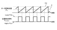
- FIG. The figure which shows the relationship between the position detection signal and motor rotation speed estimated value in Embodiment 1.
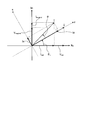
- FIG. 11 shows a vector diagram in the case where the d-axis is set on the instantaneous vector of the inverter output voltage in the vector diagram shown in FIG.
- the block diagram which shows the structure of the inverter control part in Embodiment 2.
- the block diagram which shows an example of the hardware constitutions which concern on the inverter control part of Embodiment 1 and Embodiment 2 The block diagram which shows the other example of the hardware constitutions which concern on the inverter control part of Embodiment 1 and Embodiment 2.
- FIG. 1 is a diagram illustrating a configuration of a motor drive device according to the first embodiment.
- a motor drive device 100 according to the first embodiment is a motor drive device that drives a load including a single-phase PM motor 3, and includes a DC power supply 1, a single-phase inverter 2, an inverter control unit 4, a motor current detection unit 5, and a DC.
- a power supply voltage detector 6 and a rotor position detector 7 are provided.
- Examples of the load including the single-phase PM motor 3 include a vacuum cleaner and a hand dryer provided with an electric blower.
- the DC power source 1 supplies DC power to the single phase inverter 2.
- the single-phase inverter 2 includes switching elements 211 to 214 and diodes 221 to 224 connected in antiparallel to the switching elements 211 to 214, respectively, and applies an AC voltage to the single-phase PM motor 3.
- the inverter control unit 4 outputs drive signals S1 to S4 to the switching elements 211 to 214 of the single-phase inverter 2.
- Rotor position detector 7 outputs the position detection signal S_ rotation is a signal corresponding to the rotor rotational position theta m is the rotational position of the single-phase PM motor 3 of the rotor 3a to the inverter control unit 4.
- Motor current detector 5 outputs a signal corresponding to the motor current I m flowing through the single-phase PM motor 3 to the inverter control unit 4.
- the DC power supply voltage detector 6 detects a DC voltage V dc that is the voltage of the DC power supply 1.
- Driving signals S1 ⁇ S4, the rotor rotational position theta m and pulse width modulation are generated based on the motor current I m: is (Pulse Width Modulation hereinafter referred to as "PWM”) signal.
- PWM Pulse Width Modulation
- the DC power source 1 can be a DC power source that rectifies and smoothes the AC voltage from the AC power source with a diode bridge or the like to generate a DC voltage, and there is no problem even if a DC power source such as a solar cell or a battery is used.
- the switching elements 211 to 214 of the single-phase inverter 2 include IGBTs (Insulated Gate Bipolar Transistors), MOS-FETs (Metal Oxide Semiconductor-Field Effect Transistors), thyristors, and GTOs (GateTurhOs). There is no problem even if a switching element is used. Further, there is no problem even if a semiconductor material called a wide band gap semiconductor represented by SiC, GaN or the like is used as well as Si, which is the mainstream as a semiconductor material of the switching element as described above.
- Rotor position detector 7 outputs for example, generates a position detection signal S _rotation corresponding to the rotor rotational position theta m of the motor shown in FIG. 2 to the inverter control unit 4.
- a position detection signal S_rotation which is a pulsed voltage signal corresponding to the rotor rotational position ⁇ m
- S_rotation “High level”
- S_rotation “Low level” is described as an example.
- a magnetic sensor not only a magnetic sensor but also a position detection sensor such as an encoder or a resolver can be used.
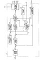
- FIG. 3 is a block diagram showing a configuration of inverter control unit 4 in the first embodiment.
- the inverter control unit 4 includes a first current control unit 411 that controls the d-axis current Id, a second current control unit 412 that controls the q-axis current Iq, and a rotation speed control that controls the motor rotation speed estimation value ⁇ m ⁇ .
- a first coordinate conversion unit 431 that performs coordinate conversion from a polar coordinate system to a coordinate system in the d-axis and q-axis (hereinafter referred to as “dq-axis coordinate system”), coordinate conversion from the dq-axis coordinate system to the polar coordinate system
- the second coordinate conversion unit 432 for performing the motor position and rotation number detection unit 44 for detecting the rotor rotation position estimated value ⁇ m ⁇ and the motor rotation number estimated value ⁇ m ⁇ in accordance with the position detection signal S_rotation , the rotation number command A rotation speed command value generation unit 45 that generates a value ⁇ *, a switching element drive signal generation unit 46 that generates drive signals S1 to S4 from an inverter output voltage command value V m *, and a q-axis current command value I q *.
- FIG. 4 is a diagram showing the relationship between the position detection signal S_rotation and the estimated motor rotation speed value ⁇ m ⁇ in the first embodiment.
- Motor position and rotation speed detector 44 may be detected using the period T _rotation position detection signal S _rotation, the motor rotation speed estimation value omega m ⁇ by the following formula (1) are shown formula.
- FIG. 5 is a diagram showing the relationship between the motor rotational speed estimated value ⁇ m ⁇ and the rotor rotational position estimated value ⁇ m ⁇ in the first embodiment.
- the rotor rotational position estimated value ⁇ m ⁇ can be calculated by integrating the motor rotational speed estimated value ⁇ m ⁇ .
- the example in FIG. 5 is a description assuming a discrete control system in the control cycle T cnt , and the rotor rotational position estimated value at the control timing n is described as ⁇ m ⁇ [n].
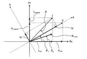
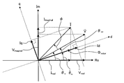
- FIG. 6 is a diagram illustrating a vector relationship at the instant vector I ⁇ and instantaneous vector V ⁇ the dq coordinate system of the inverter output voltage of the motor current.
- Non-Patent Document 1 when expressed the motor current I m in a complex vector, therefore expression is regarded as the analysis function, the real and imaginary parts of the vector are connected by the relationship of the Hilbert transform to each other .
- the current in a single-phase system is targeted, but the motor current Im is targeted as in the present invention.
- the instantaneous vector I ⁇ the motor current I m can be detected by the following equation (3).
- the first coordinate conversion unit 431 performs coordinate conversion from the single-phase alternating current to the dq coordinate system according to the above equation (4), and the d-axis current I d and the q-axis current I q represented by the following equation (5). Is calculated.
- theta V is the inverter output voltage of the phase (hereinafter referred to as "inverter output voltage phase”), utilizes the value calculated by the second coordinate conversion unit 432.
- ⁇ represents the power factor angle.
- the first coordinate conversion unit 431 is performing coordinate conversion of the instantaneous vector I ⁇ motor current I m on the inverter output voltage phase theta V.
- I m_rms represents an effective value of the motor current I m (hereinafter, referred to as “motor current effective value” as appropriate).
- the inverter output voltage phase ⁇ V is not included, and it can be seen that the d-axis current I d and the q-axis current I q are converted as DC amounts.
- the instantaneous value of the single-phase AC power P m when the instantaneous value v m (t) of the inverter output voltage and the instantaneous value i m (t) of the motor current I m are defined as in the following equation (8):
- the relationship between the d-axis current I d and the q-axis current I q with respect to the value (hereinafter referred to as “single-phase AC power instantaneous value”) P m (t) will be described.
- the first equation in the above equation (8) is an equation representing the instantaneous value of the inverter output voltage (hereinafter referred to as “inverter output single-phase voltage instantaneous value”) v m (t), and the second equation is the motor current I m.
- Is an equation representing an instantaneous value (hereinafter referred to as “motor current instantaneous value”) i m (t).
- V M_rms is the effective value of the inverter output single-phase voltage instantaneous value v m (t).
- the motor current instantaneous value i m (t) is a leading load and a capacitive load with respect to the inverter output single phase voltage instantaneous value v m (t). It may be an inductive load in which the motor current instantaneous value i m (t) is a delayed phase with respect to the phase voltage instantaneous value v m (t).
- the power factor angle ⁇ takes a negative value.
- the above expression (10) is an expression representing the instantaneous power.
- the first term represents the active power component of the instantaneous power (hereinafter referred to as “active power instantaneous value”)
- the second term represents the reactive power component of the instantaneous power (Hereinafter referred to as “reactive power instantaneous value”).
- the second coordinate conversion unit 432 that performs coordinate conversion from the dq coordinate system to the polar coordinate system, that is, the single-phase AC coordinate system will be described.
- the second coordinate conversion unit 432 uses the d-axis voltage command value V d * and the q-axis voltage command value V q * and, based on the following equation (12), the inverter output voltage command value V that is an AC voltage. Convert to m *.
- the above equation (12) is an example of a coordinate conversion equation to the inverter output voltage command value V m *, and the content of the equation (12) varies depending on the definition in the first coordinate conversion unit 431 described above. .
- the inverter output voltage phase ⁇ V used in the first coordinate conversion unit 431 corresponds to the phase angle within cos in the above equation (12). That is, the inverter output voltage phase theta V can be expressed by the following equation (13).
- Q first current control unit 411 is a feedback controller for controlling so that the d-axis current I d as described above is coincident with the d-axis current command value I d *
- a second current control unit 412 is a feedback controller that controls the shaft current I q so as to coincide with the q-axis current command value I q *.
- Each of the first current control unit 411 and the second current control unit 412 can employ, for example, a PID control system having a transfer function G PID (s) as shown in the following equation (14). .
- K p is a proportional gain
- K I is an integral gain
- K d is the differential gain
- s represents the Laplace operator.
- the rotational speed control unit 42 is a feedback controller that controls the motor rotational speed estimation value ⁇ ⁇ to coincide with the rotational speed command value ⁇ *.
- the rotational speed control unit 42 includes the first current control unit 411 or the second current control unit 412. Similar PID control or the like can be employed. Needless to say, the point of PID control, the point of feedback control, and the like are examples of the control method as in the first current control unit 411 and the second current control unit 412.
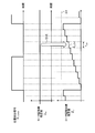
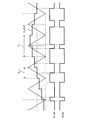
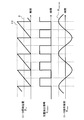
- FIG. 7 is a time chart for explaining the operation of the switching element drive signal generation unit 46.
- the thin line indicates the carrier waveform
- the thick line indicates the waveform of the inverter output voltage command value V m *.
- the lower part of FIG. 7 shows waveforms of drive signals S1 to S4 for driving the switching elements 211 to 214.
- the inverter output voltage command value V m * [n] is discretely changed.
- the high level and the low level of the drive signals S1 to S4 are determined based on the magnitude relationship between the inverter output voltage command value V m * [n] and the carrier at the control timing n.
- S1 and S4, S2 and S3 are the same signal, and S2 and S3 are waveforms inverted with respect to S1 and S4.
- a dead time is often provided.
- the dead time is described as 0, but there is no problem even if the dead time ⁇ 0.
- the generation method of the drive signals S1 to S4 in FIG. 7 is merely an example, and any method can be used as long as it is a method for generating a PWM signal.
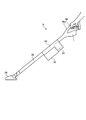
- FIG. 8 is a diagram illustrating an example of a configuration of a vacuum cleaner as an application example of the motor drive device according to the first embodiment.
- a vacuum cleaner 8 includes a DC power source 1 such as a battery, and an electric blower 81 driven by the single-phase PM motor 3 described above, and a dust collection chamber 82, a sensor 83, a suction port body 84, an extension pipe. 85 and an operation unit 86.
- the vacuum cleaner 8 drives the single-phase PM motor 3 using the DC power source 1 as a power source, performs suction from the suction port body 84, and sucks dust into the dust collection chamber 82 via the extension pipe 85. In use, the operation unit 86 is held and the electric vacuum cleaner 8 is operated.
- the operation unit 86 is provided with an operation switch 86a for adjusting the suction amount of the vacuum cleaner 8.
- the user of the vacuum cleaner 8 operates the operation switch 86a to set the operation state of the vacuum cleaner 8 to strong operation or weak operation.
- the operation unit 86 gives the rotation speed setting value ⁇ ** corresponding to the set operation state to the rotation speed command value generation unit 45 (see FIG. 3).
- the rotation speed setting value ⁇ ** is input to the rotation speed command value generation unit 45, and the rotation speed command value generation unit 45 outputs the rotation speed command value ⁇ *.
- the method of setting the rotation speed setting value ⁇ ** by the operation unit 86 is an example in the present embodiment, and other methods may be used. For example, a method of automatically setting the rotation speed setting value ⁇ ** according to the sensor 83 may be used, and any method may be used.
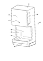
- FIG. 9 is a diagram illustrating an example of a configuration of a hand dryer as another application example of the motor driving device according to the first embodiment.
- the hand dryer 90 includes a casing 91, a hand detection sensor 92, a water receiver 93, a drain container 94, a cover 96, a sensor 97, and an intake port 98.
- an electric blower (not shown) driven by the motor driving device of the first embodiment is provided in the casing 91.
- the hand dryer 90 has a structure in which water is blown off by blowing with an electric blower by inserting a hand into the hand insertion portion 99 at the top of the water receiving portion 93 and water is stored from the water receiving portion 93 into the drain container 94.
- the sensor 97 is either a gyro sensor or a human sensor, and the control system of the inverter control unit 4 may be configured to automatically set the rotation speed setting value ⁇ ** according to the sensor 97.
- the q-axis current command value generation unit 47 outputs a q-axis current command value I q *.
- the active power can be controlled by the d-axis current I d so that the estimated rotational speed value ⁇ ⁇ matches the rotational speed command value ⁇ *.
- the d-axis current Id is controlled so that the active power increases when the rotational speed command value ⁇ * increases, and the active power decreases when the rotational speed command value ⁇ * decreases.
- the d-axis current Id is controlled so as to
- the reactive power can be controlled by the q-axis current I q , and the power factor at the time of driving the motor can be controlled.
- reactive power is controlled to be zero, it is possible to suppress only the amount that only relevant motor current I m in effective power.
- the motor current is controlled to the minimum, the copper loss of the motor including the loss in the winding resistance, the conduction loss of the inverter including the loss due to the on-resistance or the on-voltage in the switching element, and when the switching element is turned on and off Since the switching loss, which is a loss, can be suppressed, it is possible to realize high efficiency of applied products to which the motor drive device is applied.
- mode - have been described a method of controlling the active power by performing coordinate transformation to the dq-axis coordinate system parsing functions motor current I m - applying a Hilbert transform to the data current I m, Hilbert transformed mode.
- the effect of the method according to the present embodiment will be described in comparison with control using PQ conversion, which is a conventional method.
- Equation representing PQ conversion in single-phase alternating current is defined by the following equations (15-1) and (15-2).
- I P is the P-axis current
- I Q represents the Q-axis current.
- the coordinate conversion is performed using the rotor rotational position estimated value ⁇ m ⁇ , but this is merely an example, and the present invention is not limited to this.
- an active power can be controlled by the P-axis current I P, to say that the reactive power by the Q-axis current I Q is controllable can.
- representative of the d-axis current I d and the q-axis current I q and (7) is compared with the representative of the P-axis current I P and Q-axis current I Q (15-1) and (15-2) below The meaning represented by each mathematical formula is greatly different.
- the P-axis current I P and Q-axis current I Q shown in equation includes the inverter output voltage phase theta V is an AC component in the trigonometric It is.
- the current control is performed such as the first current control section 411 and the second current control section 412
- the P-axis current I P and Q-axis current I Q contains AC component
- the frequency characteristic It is necessary to design with consideration.
- the motor rotating at a high speed such as a vacuum cleaner of the controlled object
- the frequency range of the P-axis current I P and Q-axis current I Q is wide, it is necessary to control design considering the characteristics of a wide band, control Design becomes difficult.
- the trigonometric function argument is a power factor angle ⁇ that does not include an AC component
- the d-axis current I d and the q-axis current I q is a direct current amount.
- the instantaneous vector of the motor current may be generated by a different method.
- the AC component included in the motor current after coordinate conversion only needs to be smaller than the DC component, and the motor current after coordinate conversion can be regarded as a DC amount.
- the motor current after coordinate conversion can be handled as a direct current, it is not necessary to consider the frequency characteristics when designing the current controller, and control construction can be easily realized.
- the necessary active power according to the motor rotation speed can be controlled, highly efficient control can be realized.
- a load device that rotates at a high speed such as the electric vacuum cleaner shown in FIG. 8 is driven by a built-in battery
- the driving time of the battery can be prolonged.
- the capacity of the battery can be reduced by taking advantage of high-efficiency driving, the load device can be reduced in size.
- Embodiment 2 FIG. In the first embodiment, the description related to the rotational speed control and power control for the single-phase PM motor has been described. In the second embodiment, the configuration of the motor control device shown in FIG. 1 is assumed to be the same, and an additional operation in the inverter control unit 4 will be described. Before describing the additional operation in the inverter control unit 4, the vector diagram shown in FIG. 6 will be described again.
- the amount of magnetic flux of the rotor magnet of the single-phase PM motor (hereinafter referred to as “rotor magnet magnetic flux”) is defined as ⁇ rotor .
- rotor magnet magnetic flux The amount of magnetic flux of the rotor magnet of the single-phase PM motor (hereinafter referred to as “rotor magnet magnetic flux”) is defined as ⁇ rotor .
- rotor magnet magnetic flux the relationship between the rotor rotational position ⁇ m and the rotor magnet magnetic flux ⁇ rotor.
- FIG. 10 can be expressed by the following equation (17) when the rotor magnet magnetic flux ⁇ rotor is expressed as a function of the rotor rotational position estimated value ⁇ m ⁇ .
- FIG. 10 is obtained by adding the rotor magnet magnetic flux ⁇ rotor represented by the equation (17) to the vector diagram of FIG.
- FIG. 10 is a vector diagram when the d-axis current I d and the q-axis current I q are defined by the expression (5), as in the first embodiment.
- the d-axis current I d and the q-axis current I q defined by the equation (5) are defined when the d-axis is set on the instantaneous vector V ⁇ the inverter output voltage.
- the d-axis is set on the rotor magnet magnetic flux ⁇ rotor as shown in FIG. 11 will be considered.
- the d-axis current I d and the q-axis current I q are redefined by the equation (18).
- the d-axis current I d is parallel to the rotor magnet magnetic flux ⁇ rotor and the q-axis current I q is orthogonal. Therefore, the d-axis current I d can be regarded as an excitation component current, and the q-axis current I q can be regarded as a torque component current. Thereby, torque control is attained by operating q-axis current Iq .
- Equation (8) representing the instantaneous value v m (t) of the inverter output voltage and the instantaneous value i m (t) of the motor current defined in the first embodiment is re-displayed below.
- ⁇ VV is the advance angle (hereinafter referred to as “inverter output voltage advance angle”) of the instantaneous vector V ⁇ of the inverter output voltage with respect to the d axis, and is represented by the following equation (21). .
- the inverter output voltage advance angle ⁇ VV and the power factor angle ⁇ can be regarded as being constant in the steady state. Therefore, also in the vector diagram of FIG. 12, the d-axis current I d and the q-axis current I q Can be regarded as a DC amount. For this reason, a control configuration similar to that of the first embodiment can be realized.
- FIG. 13 is a block diagram showing the configuration of the inverter control unit 4 in the second embodiment. 13, parts that are the same as or equivalent to those in the configuration of the first embodiment shown in FIG. Differences from the first embodiment will be described as follows.
- the definition of the dq axis for coordinate conversion is different.
- the rotor rotational position estimation value is input as ⁇ m ⁇ , and coordinate conversion is performed using equation (18). That is, according to the example of FIG. 12, the first coordinate conversion unit 431 is performing coordinate conversion of the instantaneous vector I ⁇ motor current I m on the rotor rotational position theta m.
- the second current control unit 412 controls the q-axis current I q , but as described above, unlike the first embodiment, the second current control unit 412 can be regarded as a torque current component. It is set as a q-axis current control unit as a minor loop of the rotational speed control.
- the above is the difference between the first embodiment and the second embodiment.
- the first current control unit 411, the rotation number control unit 42, the motor position and rotation number detection unit 44, and the rotation number command value generation unit 45 are the same as those in the first embodiment, and thus detailed description thereof is omitted. .
- the rotational speed control of the single-phase PM motor can be realized as in the first embodiment, and the same effect as in the first embodiment can be obtained.
- the various control units referred to here are the first current control unit 411, the second current control unit 412, the rotation speed control unit 42, the first coordinate conversion unit 431, the second in the inverter control unit 4.
- the coordinate conversion unit 432, the motor position / rotation number detection unit 44, the rotation number command value generation unit 45, the switching element drive signal generation unit 46, the q-axis current command value generation unit 47, the Hilbert conversion unit 48, and the like correspond thereto.
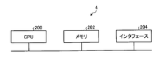
- a CPU 200 Central Processing Unit 200 that performs arithmetic operations and a memory that stores programs read by the CPU 200 are stored.
- 202 and an interface 204 for inputting and outputting signals may be included.
- the CPU 200 may be an arithmetic device, a microprocessor, a microcomputer, a processor, or a DSP (Digital Signal Processor).
- the memory 202 is, for example, a nonvolatile or volatile semiconductor memory such as a RAM (Random Access Memory), a ROM (Read Only Memory), a flash memory, an EPROM (Erasable Programmable ROM), an EEPROM (Electrically Programmable EPROM), or the like. Is applicable.
- the memory 202 stores programs for executing the functions of various control means.
- the CPU 200 executes various arithmetic processes described in the present embodiment by exchanging necessary information via the interface 204.
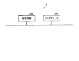
- the CPU 200 and the memory 202 shown in FIG. 14 may be replaced with a processing circuit 203 as shown in FIG.
- the processing circuit 203 is, for example, a single circuit, a composite circuit, a programmed processor, a parallel programmed processor, an ASIC (Application Specific Integrated Circuit), an FPGA (Field-Programmable Gate Array), or a combination of these. Applicable.
Landscapes
- Engineering & Computer Science (AREA)
- Power Engineering (AREA)
- Control Of Ac Motors In General (AREA)
- Control Of Motors That Do Not Use Commutators (AREA)
Abstract
Un dispositif d'entraînement de moteur 100 selon la présente invention entraîne un moteur à aimant permanent monophasé 3 et comprend : un onduleur monophasé 2 permettant d'appliquer une tension alternative au moteur à aimant permanent monophasé 3 ; une unité de détection de position de rotor 7 destinée à fournir un signal de détection de position S_rotation à une unité de commande d'onduleur 4, ledit signal de détection de position S_rotation étant un signal correspondant à la position de rotation du rotor 3a du moteur à aimant permanent monophasé 3 ; l'unité de commande d'onduleur 4 destinée à fournir des signaux de commande à des éléments de commutation 211-214 de l'onduleur monophasé 2 sur la base du signal de détection de position S_rotation et d'un courant de moteur Im s'écoulant à travers le moteur à aimant permanent monophasé 3 ; et une unité de détection de courant de moteur 5 destinée à délivrer un signal correspondant au courant de moteur Im à l'unité de commande d'onduleur 4. L'unité de commande d'onduleur 4 commande la puissance active en fonction de la vitesse de rotation du moteur à aimant permanent monophasé 3.
Priority Applications (2)
| Application Number | Priority Date | Filing Date | Title |
|---|---|---|---|
| PCT/JP2016/063105 WO2017187533A1 (fr) | 2016-04-26 | 2016-04-26 | Dispositif d'entraînement de moteur, nettoyeur électrique et sèche-mains |
| JP2018514000A JP6577665B2 (ja) | 2016-04-26 | 2016-04-26 | モータ駆動装置、電気掃除機及びハンドドライヤー |
Applications Claiming Priority (1)
| Application Number | Priority Date | Filing Date | Title |
|---|---|---|---|
| PCT/JP2016/063105 WO2017187533A1 (fr) | 2016-04-26 | 2016-04-26 | Dispositif d'entraînement de moteur, nettoyeur électrique et sèche-mains |
Publications (1)
| Publication Number | Publication Date |
|---|---|
| WO2017187533A1 true WO2017187533A1 (fr) | 2017-11-02 |
Family
ID=60160259
Family Applications (1)
| Application Number | Title | Priority Date | Filing Date |
|---|---|---|---|
| PCT/JP2016/063105 Ceased WO2017187533A1 (fr) | 2016-04-26 | 2016-04-26 | Dispositif d'entraînement de moteur, nettoyeur électrique et sèche-mains |
Country Status (2)
| Country | Link |
|---|---|
| JP (1) | JP6577665B2 (fr) |
| WO (1) | WO2017187533A1 (fr) |
Cited By (3)
| Publication number | Priority date | Publication date | Assignee | Title |
|---|---|---|---|---|
| WO2020208785A1 (fr) * | 2019-04-11 | 2020-10-15 | 三菱電機株式会社 | Dispositif d'entraînement de moteur, ventilateur électrique, aspirateur électrique et sèche-mains |
| WO2020208787A1 (fr) * | 2019-04-11 | 2020-10-15 | 三菱電機株式会社 | Dispositif d'entraînement de moteur, ventilateur électrique, aspirateur électrique et sèche-mains |
| CN113615069A (zh) * | 2019-07-29 | 2021-11-05 | 广东美的白色家电技术创新中心有限公司 | 一种无刷直流电机换相控制方法、装置及存储介质 |
Citations (2)
| Publication number | Priority date | Publication date | Assignee | Title |
|---|---|---|---|---|
| JP2002136198A (ja) * | 2000-10-19 | 2002-05-10 | Sanyo Electric Co Ltd | 電動機の制御装置 |
| JP2007159212A (ja) * | 2005-12-02 | 2007-06-21 | Hitachi Ltd | 永久磁石同期モータのベクトル制御装置,インバータモジュール、及び永久磁石同期電動機モータ定数表示システム |
-
2016
- 2016-04-26 WO PCT/JP2016/063105 patent/WO2017187533A1/fr not_active Ceased
- 2016-04-26 JP JP2018514000A patent/JP6577665B2/ja not_active Expired - Fee Related
Patent Citations (2)
| Publication number | Priority date | Publication date | Assignee | Title |
|---|---|---|---|---|
| JP2002136198A (ja) * | 2000-10-19 | 2002-05-10 | Sanyo Electric Co Ltd | 電動機の制御装置 |
| JP2007159212A (ja) * | 2005-12-02 | 2007-06-21 | Hitachi Ltd | 永久磁石同期モータのベクトル制御装置,インバータモジュール、及び永久磁石同期電動機モータ定数表示システム |
Cited By (7)
| Publication number | Priority date | Publication date | Assignee | Title |
|---|---|---|---|---|
| WO2020208785A1 (fr) * | 2019-04-11 | 2020-10-15 | 三菱電機株式会社 | Dispositif d'entraînement de moteur, ventilateur électrique, aspirateur électrique et sèche-mains |
| WO2020208787A1 (fr) * | 2019-04-11 | 2020-10-15 | 三菱電機株式会社 | Dispositif d'entraînement de moteur, ventilateur électrique, aspirateur électrique et sèche-mains |
| CN113615069A (zh) * | 2019-07-29 | 2021-11-05 | 广东美的白色家电技术创新中心有限公司 | 一种无刷直流电机换相控制方法、装置及存储介质 |
| JP2022540379A (ja) * | 2019-07-29 | 2022-09-15 | ▲広▼▲東▼美的白色家▲電▼技▲術▼▲創▼新中心有限公司 | ブラシレス直流モータの転流制御方法、装置及び記憶媒体 |
| JP7244677B2 (ja) | 2019-07-29 | 2023-03-22 | ▲広▼▲東▼美的白色家▲電▼技▲術▼▲創▼新中心有限公司 | ブラシレス直流モータの転流制御方法、装置及び記憶媒体 |
| US11689140B2 (en) | 2019-07-29 | 2023-06-27 | Guangdong Midea White Home Appliance Technology Innovation Center Co., Ltd. | Commutation control method and device for brushless direct current motor, and storage medium |
| CN113615069B (zh) * | 2019-07-29 | 2024-11-12 | 广东美的白色家电技术创新中心有限公司 | 一种无刷直流电机换相控制方法、装置及存储介质 |
Also Published As
| Publication number | Publication date |
|---|---|
| JPWO2017187533A1 (ja) | 2018-08-30 |
| JP6577665B2 (ja) | 2019-09-18 |
Similar Documents
| Publication | Publication Date | Title |
|---|---|---|
| JP6434647B2 (ja) | モータ駆動装置、電気掃除機およびハンドドライヤー | |
| JP6194466B2 (ja) | モータ駆動装置 | |
| KR102267061B1 (ko) | 동력 장치, 동력 장치의 제어방법 및 동력 장치에 포함되는 전동기 구동 장치 | |
| JP6953763B2 (ja) | モータ制御装置 | |
| JP6368523B2 (ja) | モータ制御装置 | |
| JP6269355B2 (ja) | マトリクスコンバータ、発電システムおよび力率制御方法 | |
| JP6644159B2 (ja) | モータ駆動装置、電動送風機、電気掃除機及びハンドドライヤー | |
| JP2012161143A (ja) | 永久磁石同期電動機の制御装置 | |
| JPWO2018138807A1 (ja) | モータ駆動装置、電動送風機、電気掃除機及びハンドドライヤ | |
| JP6577665B2 (ja) | モータ駆動装置、電気掃除機及びハンドドライヤー | |
| JP6896032B2 (ja) | モータ駆動装置、電気掃除機及びハンドドライヤー | |
| JP5078925B2 (ja) | 電動機の駆動装置並びに機器 | |
| JP6847195B2 (ja) | モータ駆動装置、電動送風機、電気掃除機及びハンドドライヤー | |
| JP7053955B2 (ja) | 回転機の制御装置 | |
| TWI823521B (zh) | 多相永磁轉子馬達及其閉迴路方法 | |
| JP3551911B2 (ja) | ブラシレスdcモータ制御方法およびその装置 | |
| JP7150150B2 (ja) | モータ駆動装置、電動送風機、電気掃除機及びハンドドライヤ | |
| WO2020095377A1 (fr) | Dispositif d'entraînement de charge, dispositif à cycle de réfrigération et climatiseur | |
| JP2018198479A (ja) | 同期電動機の制御装置 | |
| WO2023276181A1 (fr) | Dispositif de conversion de puissance | |
| JP4446688B2 (ja) | 多相電流供給回路及びその制御方法 | |
| JP6815470B2 (ja) | モータ駆動装置、電気掃除機およびハンドドライヤー | |
| JP6622887B2 (ja) | モータ駆動装置、電気掃除機およびハンドドライヤー | |
| JP7150152B2 (ja) | モータ駆動装置、電動送風機、電気掃除機及びハンドドライヤ | |
| WO2024069811A1 (fr) | Dispositif d'entraînement de moteur et instrument de cycle de réfrigération |
Legal Events
| Date | Code | Title | Description |
|---|---|---|---|
| ENP | Entry into the national phase |
Ref document number: 2018514000 Country of ref document: JP Kind code of ref document: A |
|
| NENP | Non-entry into the national phase |
Ref country code: DE |
|
| 121 | Ep: the epo has been informed by wipo that ep was designated in this application |
Ref document number: 16900406 Country of ref document: EP Kind code of ref document: A1 |
|
| 122 | Ep: pct application non-entry in european phase |
Ref document number: 16900406 Country of ref document: EP Kind code of ref document: A1 |