WO2017187616A1 - Dispositif d'ajustement de gaz - Google Patents
Dispositif d'ajustement de gaz Download PDFInfo
- Publication number
- WO2017187616A1 WO2017187616A1 PCT/JP2016/063429 JP2016063429W WO2017187616A1 WO 2017187616 A1 WO2017187616 A1 WO 2017187616A1 JP 2016063429 W JP2016063429 W JP 2016063429W WO 2017187616 A1 WO2017187616 A1 WO 2017187616A1
- Authority
- WO
- WIPO (PCT)
- Prior art keywords
- gas
- baffle plate
- gas supply
- supply nozzle
- mixing vessel
- Prior art date
- Legal status (The legal status is an assumption and is not a legal conclusion. Google has not performed a legal analysis and makes no representation as to the accuracy of the status listed.)
- Ceased
Links
Images




Classifications
-
- B—PERFORMING OPERATIONS; TRANSPORTING
- B01—PHYSICAL OR CHEMICAL PROCESSES OR APPARATUS IN GENERAL
- B01F—MIXING, e.g. DISSOLVING, EMULSIFYING OR DISPERSING
- B01F23/00—Mixing according to the phases to be mixed, e.g. dispersing or emulsifying
- B01F23/10—Mixing gases with gases
-
- B—PERFORMING OPERATIONS; TRANSPORTING
- B01—PHYSICAL OR CHEMICAL PROCESSES OR APPARATUS IN GENERAL
- B01F—MIXING, e.g. DISSOLVING, EMULSIFYING OR DISPERSING
- B01F23/00—Mixing according to the phases to be mixed, e.g. dispersing or emulsifying
- B01F23/20—Mixing gases with liquids
-
- B—PERFORMING OPERATIONS; TRANSPORTING
- B01—PHYSICAL OR CHEMICAL PROCESSES OR APPARATUS IN GENERAL
- B01F—MIXING, e.g. DISSOLVING, EMULSIFYING OR DISPERSING
- B01F25/00—Flow mixers; Mixers for falling materials, e.g. solid particles
- B01F25/20—Jet mixers, i.e. mixers using high-speed fluid streams
-
- F—MECHANICAL ENGINEERING; LIGHTING; HEATING; WEAPONS; BLASTING
- F02—COMBUSTION ENGINES; HOT-GAS OR COMBUSTION-PRODUCT ENGINE PLANTS
- F02M—SUPPLYING COMBUSTION ENGINES IN GENERAL WITH COMBUSTIBLE MIXTURES OR CONSTITUENTS THEREOF
- F02M21/00—Apparatus for supplying engines with non-liquid fuels, e.g. gaseous fuels stored in liquid form
- F02M21/02—Apparatus for supplying engines with non-liquid fuels, e.g. gaseous fuels stored in liquid form for gaseous fuels
-
- Y—GENERAL TAGGING OF NEW TECHNOLOGICAL DEVELOPMENTS; GENERAL TAGGING OF CROSS-SECTIONAL TECHNOLOGIES SPANNING OVER SEVERAL SECTIONS OF THE IPC; TECHNICAL SUBJECTS COVERED BY FORMER USPC CROSS-REFERENCE ART COLLECTIONS [XRACs] AND DIGESTS
- Y02—TECHNOLOGIES OR APPLICATIONS FOR MITIGATION OR ADAPTATION AGAINST CLIMATE CHANGE
- Y02T—CLIMATE CHANGE MITIGATION TECHNOLOGIES RELATED TO TRANSPORTATION
- Y02T10/00—Road transport of goods or passengers
- Y02T10/10—Internal combustion engine [ICE] based vehicles
- Y02T10/30—Use of alternative fuels, e.g. biofuels
Definitions
- the present invention relates to a technique for mixing a second gas with a first gas in a mixing vessel.
- Patent Document 1 changes the mixing ratio of the main fuel gas (for example, city gas) whose heat quantity is stable with respect to the auxiliary fuel gas (for example, biogas) whose heat quantity tends to fluctuate. Techniques for adjusting the amount of heat of the gas to a target value are described.
- the technology for stabilizing the amount of heat of the fuel gas (mixed fuel gas) supplied to the internal combustion engine by changing the mixing ratio of a plurality of types of fuel gas is a fuel having a stable amount of heat. It can not be used when it is difficult to obtain gas.
- the present invention has been made under such a background, and an object thereof is to provide a gas regulator capable of alleviating the influence of the property change associated with the mixing of the first gas and the second gas. It is to provide.
- a gas regulator is a gas regulator that regulates the mixed state of a first gas and a second gas, A cylindrical gas mixing vessel whose end face is closed; A gas supply pipe for supplying the second gas to a gas mixing container containing the first gas; It is connected to the gas supply pipe, and is provided in the gas mixing container so as to extend along the axial direction of the gas mixing container from one end face side of the gas mixing container, and a gas supply hole is formed; An elongated cylindrical gas supply nozzle in which a plurality of gas discharge sections, which are regions, are discretely disposed along the extending direction; From the other end face opposite to the one end face, the gas extraction pipe for extracting the gas in the gas mixing vessel, the arrangement position of the gas discharge portion on the most distal end side of the gas supply nozzle, and the gas mixing
- the gas mixing vessel is disposed between the inside of the vessel and the extraction position of the gas to the gas extraction pipe, and is directed in the direction intersecting with the flow of the gas flowing along the inner peripheral surface of the gas mixing vessel
- the gas regulator may have the following features.
- A) Each of the plurality of gas discharge portions is formed with a plurality of gas supply holes along the circumferential direction of the gas supply nozzle, and from the base end side to the tip end side of the gas supply nozzle And the space between the adjacent gas discharge parts is arranged to be gradually larger.
- An end of the baffle plate is provided with a ridge-like projection which is formed in the direction to block the gas flowing along the plate surface of the baffle plate after blocking by the baffle plate.
- At least one of the first gas and the second gas contains mist
- the base end side of the gas supply nozzle is a tip end
- the axial direction is directed in the direction of gravity so as to be positioned above the side
- the baffle plate is directed from the inner peripheral surface side of the gas mixing container toward the ridged protrusion side
- the height position of the surface is formed to be gradually lowered, and an opening for discharging the collected liquid downward from the mist which collides with the baffle plate is formed in the ridged projection.
- a drain pipe for draining the liquid dropped through the opening portion is connected to the other end face which is the bottom portion of the gas mixing container, and the gas outlet pipe is connected to the drain port.
- the first gas and the second gas are fuel gases having different calorific values, and an internal combustion engine using the fuel gas as a fuel is provided downstream of the gas extraction pipe.
- the fuel gas which is the first gas and the second gas, is a boil-off gas generated in a storage tank storing liquefied natural gas.
- the second gas for the first gas is supplied. Mixing gradually progresses.
- a baffle plate is provided in a direction intersecting the flow of the gas flowing along the inner peripheral surface of the gas mixing vessel, so the flow direction of the gas is changed to The mixing can be advanced to suppress the rapid property change of the gas extracted from the gas regulator.
- FIG. 5 is a first cross-sectional plan view of the gas conditioner.
- FIG. 6 is a second cross-sectional plan view of the gas conditioner. It is a 1st action view of the said gas regulator. It is a 2nd operation view of the said gas regulator. It is an action view of the gas regulator concerning other embodiments.
- It is a vertical side view of the gas regulator which concerns on other embodiment.
- It is a schematic diagram of the LNG receiving installation provided with the gas adjustment apparatus. It is a schematic diagram of the straight pipe which concerns on a comparative example. It is 1st explanatory drawing which shows the result of an Example and a comparative example. It is a 1st explanatory view showing the result of other comparative examples. It is 2nd explanatory drawing which shows the result of an Example and a comparative example. It is 2nd explanatory drawing which shows the result of other comparative examples.
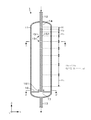
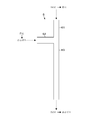
- FIG. 1 is a vertical cross-sectional side view of the gas conditioning apparatus 1
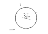
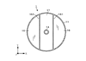
- FIGS. 2 and 3 are cross-sectional planes in which the gas conditioning apparatus 1 is viewed from the positions of AA ′ and BB ′ shown in FIG. 1.
- FIG. 1 is a vertical cross-sectional side view of the gas conditioning apparatus 1
- FIGS. 2 and 3 are cross-sectional planes in which the gas conditioning apparatus 1 is viewed from the positions of AA ′ and BB ′ shown in FIG. 1.
- FIG. 1 is a vertical cross-sectional side view of the gas conditioning apparatus 1
- FIGS. 2 and 3 are cross-sectional planes in which the gas conditioning apparatus 1 is viewed from the positions of AA ′ and BB ′ shown in FIG. 1.
- FIG. 1 is a vertical cross-sectional side view of the gas conditioning apparatus 1
- FIGS. 2 and 3 are cross-sectional planes in which the gas conditioning apparatus 1 is viewed from the positions of AA ′ and BB ′ shown in FIG. 1.
- the gas adjustment device 1 of this example is a gas when supplying the second gas having different properties (for example, the amount of heat of the fuel gas) from the first gas to the gas mixing vessel 11 in which the first gas is contained. It has a function of adjusting the state of mixture of gases so as to alleviate the sudden property change of the mixed gas extracted from the mixing container 11.
- the gas adjustment apparatus 1 includes a gas mixing vessel 11 in which gas mixing is performed, a gas supply pipe 12 for supplying a second gas, and the inside of the gas mixing vessel 11.
- the gas mixing vessel 11 of this example is configured as a cylindrical vessel whose upper and lower end faces are closed, and is vertically disposed with its central axis oriented in the direction of gravity (the Z-axis direction shown in FIG. 1). .
- the cylindrical container used as the gas mixing container 11 has a height in the range of several tens cm to a few tens m, and the ratio (L / D) of the height L to the diameter D of the cylinder is in the range 2 to 10 Can be illustrated.
- a gas supply pipe 12 to which plural types of gases are supplied is connected to an end surface (one end surface) on the upper side of the gas mixing container 11.
- a gas extraction pipe 13 for extracting the gas in the gas mixing container 11 is connected to an end surface (other end surface) on the bottom side of the gas mixing container 11.
- a cylindrical gas supply nozzle 14 consisting of an elongated straight pipe extends up and down along the direction of the central axis toward the inside of the gas mixing vessel 11. It is provided as.
- the diameter of the gas supply nozzle 14 is 1/3 or less of the diameter of the gas mixing vessel 11, and the length of the gas supply nozzle 14 is about 50 to 90% of the height of the gas mixing vessel 11.
- the proximal end side of the gas supply nozzle 14 is in communication with the gas supply pipe 12 and can receive the gas supplied from the gas supply nozzle 14.
- the end face on the tip end side of the gas supply nozzle 14 is closed.
- a gas supply hole 151 for supplying the gas flowing into the gas supply nozzle 14 through the gas supply pipe 12 into the gas mixing container 11 is formed on the side peripheral surface of the gas supply nozzle 14. As shown in FIG. 2, a plurality of gas supply holes 151 are formed in the gas supply nozzle 14 along the circumferential direction of the gas supply nozzle 14.
- a gas discharge unit 15 the above-described region in which the plurality of gas supply holes 151 are formed along the circumferential direction of the gas supply nozzle 14 is referred to as a gas discharge unit 15.
- gas supply nozzle 14 of the present example four gas supply holes 151 are arranged at equal intervals along the circumferential direction of the gas supply nozzle 14 in each gas discharge portion 15 The gas can be discharged in four directions toward the inner space of the mixing container 11.
- the interval H k may be set on the basis of other ideas.
- baffle plates 16 are provided between the extraction position. Each baffle plate 16 is directed in the direction intersecting the flow of gas flowing along the inner peripheral surface of the gas mixing vessel 11 (the direction along the XY plane shown in FIG. 1). It is provided to block part of the
- each baffle plate 16 sets two strings in parallel within the circular cross section of the gas mixing vessel 11 across the arrangement area of the gas supply nozzle 14, each chord And the inner peripheral surface of the gas mixing vessel 11 are closed. Therefore, the area sandwiched between the two strings is an open area 17 where the baffle plate is not provided.
- the baffle plate 16 when viewing the cross section of the gas mixing vessel 11 along the circumferential direction with the gas supply nozzle 14 as a center, the baffle plate 16 The provided area and the area where the baffle plate is not provided (opening area 17) are alternately arranged.
- a ridge-like projection 161 projects in a direction (upward direction) to stop the flow of gas flowing along the plate surface of the baffle plate 16 It is provided.
- the height of the ridge-like projections 161 is set to, for example, about several centimeters to several tens of centimeters.
- the tip (lower end) of the gas supply nozzle 14 is closer to the tip of the gas discharger 15 disposed on the most distal side. It extends downward and reaches the above-mentioned opening area 17. This is to facilitate the manufacture of the gas discharger 15 disposed at the forefront.
- extending the tip of the gas supply nozzle 14 to the position where the baffle plate 16 is disposed is not an essential requirement, and the gas supply at a position near the gas discharge unit 15 disposed on the above-described most distal end side The nozzle 14 may be terminated.
- the operation of the gas regulator 1 having the configuration described above will be described.
- the inside of the gas mixing container 11 is in a state in which the first gas is accommodated.
- the second gas is supplied from the gas supply pipe 12
- the second gas is discharged from the gas supply holes 151 formed in each gas discharge portion 15 of the gas supply nozzle 14 into the gas mixing container 11. Ru.
- the gas adjustment device 1 of the present example since the plurality of gas discharge portions 15 are discretely arranged along the extending direction of the gas supply nozzle 14 (axial direction of the gas mixing container 11), the first, A region in which the second gas mixture progresses is dispersed in the vicinity of each gas discharge unit 15. As a result, compared to the case where the second gas is supplied directly from the gas supply pipe 12 into the gas mixing vessel 11 without providing the gas supply nozzle 14 (comparative example 1-1 described later), the gas extraction is performed. The amount of property fluctuation per unit time of the gas extracted from the pipe 13 can be suppressed.
- the flow rate of the gas flowing around the gas discharger 15 increases toward the tip end side as compared with the base end side of the gas supply nozzle 14.
- the gas discharge parts 15 are arranged at equal intervals, for example, and no measures are taken, the flow velocity of the gas flowing around the gas discharge part 15 as it goes to the tip end side of the gas supply nozzle 14 Will rise.
- the gas in the gas mixing container 11 is extracted from the gas extraction pipe 13 while the mixing with the second gas discharged from the gas supply hole 151 of the gas discharge unit 15 does not proceed sufficiently. It becomes a state of blowout. Thereafter, when the second gas discharged into the gas mixing vessel 11 reaches the gas extraction pipe 13 without sufficiently advancing the mixing with the first gas, the concentration of the second gas becomes rapidly high. Therefore, the amount of property fluctuation per unit time becomes large.
- Each gas discharge part 15 is arrange
- FIGS. 4 and 5 schematically show the flow of the gas (second gas) discharged from the gas supply holes 151 of the gas discharge unit 15 disposed on the extreme end side.
- the flow of the gas discharged from the gas supply hole 151 is indicated by a broken arrow.
- the mixing with the gas in the gas mixing container 11 proceeds even during a period in which the second gas discharged from the gas supply hole 151 flows on the streamline indicated by the broken arrow. Therefore, compared with the proximal end of the broken arrow (the outlet of the gas supply hole 151), the mixing of the first and second gases is advanced at the distal end of the broken arrow.
- the gas discharged from the gas supply holes 151 flows radially outward in the gas mixing vessel 11, and is then positioned near the inner circumferential surface of the gas mixing vessel 11. Change the flow direction downward.
- the baffle plate 16 in the area
- the baffle plate 16 in only one stage between the arrangement position of the gas discharge portion 15 on the tip end side of the gas supply nozzle 14 and the extraction position of the gas to the gas extraction pipe 13, gas mixing While suppressing the increase in pressure loss in the container 11, the gas vortex shown in FIG. 4 can be formed to allow the gas mixing to proceed.
- the gas B which is the second gas is supplied from the gas supply nozzle 14 to the gas mixing container 11 in which the gas A is stored as the first gas, for example, by the action of the gas adjustment device 1 described above, the gas The concentration of the gas B in the gas extracted from the extraction pipe 13 is increased. At this time, since the rapid concentration change in the gas extracted from the gas extraction pipe 13 is suppressed by the actions of the gas supply nozzle 14 and the baffle plate 16 described above, the property fluctuation per unit time of the gas The amount can be kept small. Then, when the supply of the gas A from the gas supply nozzle 14 is continued, the concentration of the gas B in the gas mixing vessel 11 becomes close to 100% (1 in molar fraction), and the gas extracted from the gas extraction pipe 13 The properties of are stable.
- the gas B in the gas mixing vessel 11 corresponds to the first gas, and from the gas supply pipe 12
- the supplied gas corresponds to the second gas, and the mixing operation similar to the above-described example is performed.
- the gas regulator 1 According to the gas regulator 1 according to the present embodiment, the following effects can be obtained. Since the gas is supplied dispersed into the gas mixing vessel 11 from the elongated cylindrical gas supply nozzle 14 in which the plurality of gas discharge portions 15 are discretely arranged, the second gas for the first gas is supplied Mixing gradually progresses. Furthermore, since the baffle plate 16 is provided on the downstream side of the gas discharge unit 15 at the most distal end in the direction intersecting the flow of the gas flowing along the inner peripheral surface of the gas mixing vessel 11, as shown in FIG. As shown, it is possible to change the flow direction of the gas to advance the mixing of the gas, and to suppress the rapid property change of the gas extracted from the gas adjustment device 1.
- the gas containing the mist 21 may be either the first gas contained in the gas mixing container 11 or the second gas supplied into the gas mixing container 11 from the gas supply nozzle 14. It may be both.
- the baffle plate 16a of this example is formed so that the height position of the plate surface is gradually lowered from the inner peripheral surface side of the gas mixing vessel 11 toward the ridge-like protrusion 161 side, and has an inclined surface.
- the mist 21 which has flowed down the inside of the gas mixing vessel 11 according to the flow of gas collides with the baffle plate 16 a and is collected, becoming a liquid film-like liquid 22, It flows on the inclined surface of the plate 16a.
- An opening 172 for discharging the liquid 22 to the lower side of the baffle plate 16 a is formed in the ridge-like protrusion 161.
- a drain pipe 18 is connected to the bottom of the gas mixing container 11, and the liquid 22 dropped through the opening 172 is drained to the outside through the drain pipe 18.
- the gas extraction piping 13 is connected to the height position between the connection position of the drainage pipe 18 and the arrangement position of the baffle plate 16 a, and the gas separated from the liquid 22 is extracted from the gas mixing container 11 .
- the gas mixing vessel 11 of the gas conditioning apparatus is not limited to the case where the gas mixing vessel 11 is disposed vertically so that the axial direction coincides with the gravity direction.
- FIG. 7 shows an example of the gas conditioning apparatus 1a including the gas mixing vessel 11 which is horizontally disposed with the axial direction oriented in the horizontal direction.
- components common to those of the gas adjusting device 1 shown in FIGS. 1 to 6 are denoted by the same reference numerals as those used in these figures.
- the extending direction of the gas supply nozzle 14 is also the horizontal direction.
- the gas supply nozzle 14 may be supported by the support column 19 provided between the inner peripheral surface of the gas mixing container 11 as shown in FIG.
- the gas supply piping 12 connected to the gas supply nozzle 14 is not limited to the case where it is comprised by one piping connected to the end surface by the side of the upper part of the gas mixing container 11 like the example shown in FIG.
- the first gas supply pipe 12a for supplying the gas A and the second gas supply pipe 12b for supplying the gas B are joined at a position near the end face in the gas mixing vessel 11.
- the gas supply nozzle 14 may be connected to the downstream side of the gas supply pipes 12a and 12b.
- the arrangement interval (H k ) of the gas discharge unit 15 is from the proximal end side to the distal end side of the gas supply nozzle 14.
- interval of the gas discharge part 15 is not limited to this example.
- the gas discharge unit 15 may be arranged at intervals.
- the gas discharge portions 15 may be arranged at equal intervals, and other measures may be taken to suppress the occurrence of the blow through phenomenon.
- the opening diameter of the gas supply hole 151 is gradually reduced from the proximal end side to the distal end side of the gas supply nozzle 14 to increase the discharge flow rate of the second gas, and the gas mixing container 11 is formed.
- a conical gas mixing vessel 11 in which the radius of the cross section increases from the base end side to the tip end side of the gas supply nozzle 14 or a method for promoting the mixing with the gas inside the gas mixing vessel The method of suppressing the rise of the flow velocity accompanying the confluence of the gas flowing inside 11 and the second gas supplied from the gas supply nozzle 14 can be exemplified.
- FIG. 7 shows an example of the baffle plate 16 in which the installation of the hook-like protrusions 161 is omitted.
- the gas flows flowing inward in the radial direction of the gas mixing container 11 along the baffle plate 16 are in the central region of the gas mixing container 11 By merging, a change in the flow direction and the formation of a vortex occur, and the mixing with the gas in the gas mixing vessel 11 can be further advanced.
- the present invention may be applied to the adjustment device 1.
- the arrangement interval setting of the gas supply piping 12 and the gas discharge part 15 shown in FIG. 1, the baffle plate 16 provided with the ridge-like projection part 161 is applied to the gas adjustment device 1a of horizontal installation of FIG. Of course it is good.
- the number and arrangement of the gas supply holes 151 formed in each of the gas discharge portions 15 are not limited to the example shown in FIG. For example, by changing the formation direction of the gas supply holes 151 on the side surface of the gas supply nozzle 14 and forming the gas supply holes 151 one by one in each gas discharge portion 15, gas in different directions in each gas discharge portion 15 It may be configured to be discharged.
- a plurality of rows of gas supply holes 151 in which a plurality of gas supply holes 151 are arranged at equal intervals along the circumferential direction of the gas supply nozzle 14, may be arranged vertically.
- the plurality of gas supply holes 151 may be arranged in a spiral along the circumferential direction of the gas supply nozzle 14.
- the gas supply nozzle 14 may be configured using a spiral thin tube extending along the direction of the central axis of the gas mixing container 11.
- the planar shape of the opening area 17 formed between the baffle plates 16 is not limited to the example shown in FIG.
- an open area 17 extending in the X-axis direction in FIG. 3 may be added to form a cross-shaped open area 17, or more open areas 17 may be radially emitted from the center position of the cross section of the gas mixing vessel 11. (In these cases, the width of the opening area 17 is appropriately adjusted to secure the arrangement area of the baffle plate 16).
- the opening area 17 extends to the inner peripheral surface side of the gas mixing vessel 11, for example, the central area of the cross section of the gas mixing vessel 11 Only the circular opening area 17 may be provided.
- the gas flowing in the vicinity of the inner circumferential surface passes through the opening area 17 and reaches the gas extraction pipe 13 (FIG. 5) and is interrupted by the baffle plate 16 (FIG. 4)
- the action of forming the time lag of the gas reaching the gas extraction pipe 13 is reduced, the effect of promoting the mixing of the gas accompanying the provision of the baffle plate 16 is still exhibited.
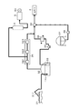
- FIG. 8 shows an example in which the vertically mounted gas regulator 1 is provided, but the configuration on the receiving facility side is the same even in the case where the horizontally mounted gas regulator 1a is provided.
- the receiving facility shown in FIG. 8 includes a gas engine 5 which is an internal combustion engine that uses as a fuel Boil Off Gas (BOG) generated in the LNG tank 32.
- the gas regulator 1 of this example is provided on the upstream side of the gas engine 5.
- the LNG stored in the LNG tank 32 is pumped from the LNG tank 32 by the LNG pump 33 and the delivery pump 35, vaporized by the LNG vaporizer 36, After adjusting the amount of heat for adding the LPG delivered from the LPG tank 37 by the LPG pump 38 in the adjustment unit 39, the adjustment unit 39 is shipped to the customer 4.
- BOG is generated by the vaporization of the LNG.
- BOG is boosted by a BOG compressor 34 having a plurality of compression stages 341 to 343 and then discharged to the customer 4 together with the vaporized LNG, or reliquefied and returned to the LNG tank 32.
- FIG. 8 shows an example in which BOG is discharged to the customer 4 together with the vaporized LNG).
- the LNG tank 32 receives the LNG from the LNG tanker 31 via the unloading arm 311. At this time, the amount of BOG generated in the LNG tank 32 may increase to several times the normal time.
- a gas engine 5 is provided using BOG as a fuel as a destination of use of surplus BOG, and the gas engine 5 can be driven to cause the generator 51 to generate power.
- the gas engine 5 may be provided with a restriction on the amount of heat quantity fluctuation per unit time of the fuel gas to be used.
- the heat quantity of BOG may change significantly. Therefore, as shown in FIG. 8, by providing the gas adjustment device 1 of the present example on the upstream side of the gas engine 5, it is possible to alleviate the variation in the amount of heat per unit time for BOG supplied to the gas engine 5.
- BOG stored in the gas adjustment device 1 before the change in heat of BOG occurs corresponds to the first gas, and the gas adjustment device 1 is generated according to the change in the amount of heat.
- the supplied BOG corresponds to the second gas.
- a pressure control valve for controlling the pressure in the gas mixing vessel 11 is provided downstream of the gas conditioning device 1, and the pressure in the gas mixing vessel 11 is increased or decreased to increase or decrease the amount of BOG contained in the gas mixing vessel 11. May be When the BOG generation amount in the LNG tank 32 increases and reaches the upper limit of the dispensable amount to the customer 4 and the possible supply amount of BOG to the gas engine 5, the BOG storage amount in the gas conditioning device 1 is temporarily It can also be used as a gas holder that absorbs excess BOG.
- the present invention is not limited to the case where BOG is used as the fuel gas, and the gas vaporized by the LNG vaporizer 36 or a gas received from the outside may be used as the fuel gas and supplied to the gas engine 5 to generate power.
- the gas conditioners 1 and 1a can be applied.
- the gas capable of alleviating the property change using the gas adjustment devices 1 and 1a is not limited to the fuel gas.
- the present invention can also be applied to the supply of gas to equipment and processes having a limited amount of property fluctuation per unit time, such as a change in the composition of the source gas supplied to the catalytic reaction.
- Simulation 1 Changes in properties and the like when the second gas was supplied to various spaces in which the first gas was stored were analyzed by CFD (Computational Fluid Dynamics).
- A. Simulation Conditions (Example) The first gas BOG (heat quantity (low calorific value, the same applies hereinafter): 29.8 MJ / Nm 3 ) is accommodated in the gas regulator 1 described with reference to FIGS. 1 to 3. Pipe 13 when the second gas city gas (heat quantity: 40.5 MJ / Nm 3 ) is supplied at 3,287 [Nm 3 / h] from the gas supply pipe 12 in the initial state.
- the gas mixing vessel 11 has a diameter of 3 [m], a volume of about 65 [m 3 ], and the gas supply nozzle 14 uses 150 A (outer diameter 165.2 [mm]) piping.
- the hole diameter of 151 is 15 mm, and the opening width (the width in the X direction in FIG. 3) of the opening area 17 formed between the baffle plates 16 is 237 mm.
- the software of CFD analysis used FLUENT (registered trademark) of ANSYS.
- Comparative Example 1-1 A simulation similar to that of the example was performed using the gas mixing vessel 11 in which the gas supply nozzle 14 and the baffle plate 16 were not provided. The diameter and volume of the gas mixing vessel 11 are the same as in the embodiment. Comparative Example 1-2 As shown in FIG. 9, the fuel gas is switched between the first supply pipe 61 for supplying BOG and the second supply pipe 62 for supplying city gas. The same simulation as that of the example was performed on the fuel gas at the outlet of the straight pipe 63 when switching of the fuel gas was performed for the straight pipe 63. The volume of the straight pipe 63 is 0.042 [m 3 ]
- FIG. 10 The concentration change of the city gas in the fuel gas and the time-dependent change of the calorific value according to the example and the comparative example 1-1 are shown in FIG. 10, and the same result according to the comparative example 1-2 is shown in FIG.
- the horizontal axis in FIGS. 10 and 11 indicates the elapsed time since the start of the city gas supply, and the vertical axis on the left side indicates the city gas concentration (molar fraction [ ⁇ ]).
- the vertical axis on the right side indicates the calorific value (low calorific value [MJ / Nm 3 ]) of the fuel gas at the outlet position.
- FIG. 12 the temporal change of the heat quantity fluctuation amount per unit time according to the example and the comparative example 1-1 is shown in FIG. 12, and the similar result according to the comparative example 1-2 is shown in FIG.
- the horizontal axis of FIGS. 12 and 13 indicates the elapsed time since the start of the city gas supply, and the vertical axis indicates the heat quantity fluctuation amount [MJ / Nm 3 / min] per unit time.
- Example and Comparative Example 1-1 the molar fraction of the city gas in the fuel gas on the outlet side rises to nearly 90% in about 15 minutes, and this molar fraction changes.
- the amount of heat of the fuel gas also gradually increased.
- the fuel gas on the outlet side was switched from BOG to city gas in an extremely short time of less than 0.01 minutes (0.6 seconds) (FIG. 11).
- the heat quantity fluctuation quantity per unit time is suppressed to 1.0 [MJ / Nm 3 / min] or less I was able to.
- this value exceeds the target value.
- Comparative Example 1-2 the heat quantity fluctuation amount per unit time has increased to several thousand times the target value.
- Simulation 2 CFD analysis was performed on the influence of the installation of the baffle plate 16 on the heat quantity fluctuation per unit time.
- A. Simulation Conditions (Comparative Example 2-1) In the case where the baffle plate 16 was not provided in the gas adjustment device 1 of Example 1, the same simulation as in Example 1 was performed to determine the maximum value of the heat quantity fluctuation amount per unit time. .
Landscapes
- Chemical & Material Sciences (AREA)
- Engineering & Computer Science (AREA)
- Chemical Kinetics & Catalysis (AREA)
- General Chemical & Material Sciences (AREA)
- Oil, Petroleum & Natural Gas (AREA)
- Combustion & Propulsion (AREA)
- Mechanical Engineering (AREA)
- General Engineering & Computer Science (AREA)
- Accessories For Mixers (AREA)
Abstract
La présente invention a pour but de fournir un dispositif d'ajustement de gaz qui est capable d'atténuer les effets de changements de propriété qui accompagnent le mélange d'un premier gaz et d'un second gaz. Pour atteindre ce but, dans ce dispositif d'ajustement de gaz 1 pour ajuster l'état de mélange d'un premier gaz et d'un second gaz, un tuyau d'alimentation en gaz 12 pour fournir le second gaz, et un tuyau d'extraction de gaz 13 pour extraire un gaz d'un récipient de mélange de gaz 11, dans lequel le premier gaz est reçu, sont reliés dans le récipient de mélange de gaz 11. Une buse d'alimentation en gaz tubulaire, mince et longue 14, est disposée à l'intérieur du récipient de mélange de gaz 11. Une pluralité de sections d'évacuation de gaz 15, qui sont des zones dans lesquelles des trous d'alimentation en gaz 151 sont formés, sont disposées de manière distincte. Une chicane 16 est disposée sur le côté aval de l'emplacement auquel la section d'évacuation de gaz 15 sur le côté extrémité de pointe de la buse d'alimentation en gaz 14 est disposé, de façon à bloquer une partie de la section transversale du récipient de mélange de gaz 11.
Priority Applications (5)
| Application Number | Priority Date | Filing Date | Title |
|---|---|---|---|
| PCT/JP2016/063429 WO2017187616A1 (fr) | 2016-04-28 | 2016-04-28 | Dispositif d'ajustement de gaz |
| PCT/JP2017/016788 WO2017188395A1 (fr) | 2016-04-28 | 2017-04-27 | Dispositif d'ajustement de fluide |
| CN201790000246.6U CN207576152U (zh) | 2016-04-28 | 2017-04-27 | 流体调整装置 |
| JP2018514708A JP6970083B2 (ja) | 2016-04-28 | 2017-04-27 | 流体調整装置 |
| PH12018502277A PH12018502277A1 (en) | 2016-04-28 | 2018-10-26 | Fluid adjustment device |
Applications Claiming Priority (1)
| Application Number | Priority Date | Filing Date | Title |
|---|---|---|---|
| PCT/JP2016/063429 WO2017187616A1 (fr) | 2016-04-28 | 2016-04-28 | Dispositif d'ajustement de gaz |
Publications (1)
| Publication Number | Publication Date |
|---|---|
| WO2017187616A1 true WO2017187616A1 (fr) | 2017-11-02 |
Family
ID=60159868
Family Applications (2)
| Application Number | Title | Priority Date | Filing Date |
|---|---|---|---|
| PCT/JP2016/063429 Ceased WO2017187616A1 (fr) | 2016-04-28 | 2016-04-28 | Dispositif d'ajustement de gaz |
| PCT/JP2017/016788 Ceased WO2017188395A1 (fr) | 2016-04-28 | 2017-04-27 | Dispositif d'ajustement de fluide |
Family Applications After (1)
| Application Number | Title | Priority Date | Filing Date |
|---|---|---|---|
| PCT/JP2017/016788 Ceased WO2017188395A1 (fr) | 2016-04-28 | 2017-04-27 | Dispositif d'ajustement de fluide |
Country Status (4)
| Country | Link |
|---|---|
| JP (1) | JP6970083B2 (fr) |
| CN (1) | CN207576152U (fr) |
| PH (1) | PH12018502277A1 (fr) |
| WO (2) | WO2017187616A1 (fr) |
Families Citing this family (2)
| Publication number | Priority date | Publication date | Assignee | Title |
|---|---|---|---|---|
| CN112007479B (zh) * | 2020-08-24 | 2023-05-09 | 中国石油化工股份有限公司 | 一种常压塔顶油气洗涤脱氯装置及方法 |
| CN112007478B (zh) * | 2020-08-24 | 2023-05-09 | 中国石油化工股份有限公司 | 一种常压塔顶油气洗涤脱氯系统及方法 |
Citations (7)
| Publication number | Priority date | Publication date | Assignee | Title |
|---|---|---|---|---|
| GB1484489A (en) * | 1973-12-27 | 1977-09-01 | Comp Generale Electricite | Device for mixing fluids |
| JPS62243936A (ja) * | 1986-04-16 | 1987-10-24 | Mitsubishi Heavy Ind Ltd | 機関の燃料制御装置 |
| JP2004016892A (ja) * | 2002-06-14 | 2004-01-22 | Mitsubishi Electric Corp | 排ガス処理方法およびそのための装置 |
| JP2005142092A (ja) * | 2003-11-07 | 2005-06-02 | Toyota Motor Corp | ガス処理装置 |
| JP2009029680A (ja) * | 2007-07-30 | 2009-02-12 | Jgc Corp | ガス混合装置及び合成ガス製造装置 |
| JP2011169294A (ja) * | 2010-02-22 | 2011-09-01 | Toho Gas Co Ltd | 燃焼システムに用いるガス混合装置 |
| US20130291525A1 (en) * | 2012-05-07 | 2013-11-07 | Pradeep K. GANESAN | Heater tube for an exhaust system |
Family Cites Families (7)
| Publication number | Priority date | Publication date | Assignee | Title |
|---|---|---|---|---|
| JPS5123051U (fr) * | 1974-08-08 | 1976-02-20 | ||
| AUPP042197A0 (en) * | 1997-11-18 | 1997-12-11 | Luminis Pty Limited | Oscillating jets |
| MY161064A (en) * | 2005-06-13 | 2017-04-14 | Osaka Gas Co Ltd | Method and apparatus for producing hydrogen-containing gas |
| JP6049530B2 (ja) * | 2013-04-22 | 2016-12-21 | 大阪瓦斯株式会社 | 混合気供給システム及び混合気供給システムに用いる混合気供給装置 |
| WO2015037678A1 (fr) * | 2013-09-12 | 2015-03-19 | Hattori Mitsuharu | Procédé et dispositif de fabrication d'huile aqueuse transparente compatible |
| JP2015075097A (ja) * | 2013-10-09 | 2015-04-20 | 十七 市川 | 気液混合燃料製造装置 |
| JP6196140B2 (ja) * | 2013-12-05 | 2017-09-13 | 東京瓦斯株式会社 | 流体配管の管構造及び流体拡散装置 |
-
2016
- 2016-04-28 WO PCT/JP2016/063429 patent/WO2017187616A1/fr not_active Ceased
-
2017
- 2017-04-27 JP JP2018514708A patent/JP6970083B2/ja active Active
- 2017-04-27 WO PCT/JP2017/016788 patent/WO2017188395A1/fr not_active Ceased
- 2017-04-27 CN CN201790000246.6U patent/CN207576152U/zh active Active
-
2018
- 2018-10-26 PH PH12018502277A patent/PH12018502277A1/en unknown
Patent Citations (7)
| Publication number | Priority date | Publication date | Assignee | Title |
|---|---|---|---|---|
| GB1484489A (en) * | 1973-12-27 | 1977-09-01 | Comp Generale Electricite | Device for mixing fluids |
| JPS62243936A (ja) * | 1986-04-16 | 1987-10-24 | Mitsubishi Heavy Ind Ltd | 機関の燃料制御装置 |
| JP2004016892A (ja) * | 2002-06-14 | 2004-01-22 | Mitsubishi Electric Corp | 排ガス処理方法およびそのための装置 |
| JP2005142092A (ja) * | 2003-11-07 | 2005-06-02 | Toyota Motor Corp | ガス処理装置 |
| JP2009029680A (ja) * | 2007-07-30 | 2009-02-12 | Jgc Corp | ガス混合装置及び合成ガス製造装置 |
| JP2011169294A (ja) * | 2010-02-22 | 2011-09-01 | Toho Gas Co Ltd | 燃焼システムに用いるガス混合装置 |
| US20130291525A1 (en) * | 2012-05-07 | 2013-11-07 | Pradeep K. GANESAN | Heater tube for an exhaust system |
Also Published As
| Publication number | Publication date |
|---|---|
| WO2017188395A1 (fr) | 2017-11-02 |
| PH12018502277A1 (en) | 2019-09-09 |
| JPWO2017188395A1 (ja) | 2019-03-07 |
| JP6970083B2 (ja) | 2021-11-24 |
| CN207576152U (zh) | 2018-07-06 |
Similar Documents
| Publication | Publication Date | Title |
|---|---|---|
| US10300409B2 (en) | High-density fine bubble-containing liquid producing method and high-density fine bubble-containing liquid producing apparatus | |
| WO2015010062A1 (fr) | Appareil et procédés pour mélanger des combustibles reformables et un gaz et/ou de la vapeur contenant de l'oxygène | |
| US9901870B2 (en) | Carbon dioxide capturing system and method of operating same | |
| JP2021534363A (ja) | 火力発電所の排ガス処理装置 | |
| JP2004504146A (ja) | ガスコンデンサ | |
| JP6970083B2 (ja) | 流体調整装置 | |
| JP6218867B2 (ja) | 凝縮設備 | |
| US9400107B2 (en) | Fluid composite, device for producing thereof and system of use | |
| JP5507304B2 (ja) | 気化ガス製造システム | |
| JP6303796B2 (ja) | 貯留槽内低温液体の混合方法及び装置 | |
| JP6218868B2 (ja) | 気液混合器 | |
| KR20250048547A (ko) | 액화 가스 용례에서 무 증발 작동을 위한 방법 및 시스템 | |
| JP5030038B2 (ja) | 乳化剤を含まないエマルジョン燃料の製造装置およびその運転方法 | |
| JP2007533419A (ja) | 2相ストリームを所望の気体/液体比を有する2つ以上のストリームに分割するためのデバイス | |
| US20180117542A1 (en) | Flow control device for mitigating thermal stratification in mixing tee pipe | |
| KR20200132244A (ko) | 액화가스의 기화저감장치 | |
| JP6512888B2 (ja) | 液化天然ガス(lng)設備の運転制御装置 | |
| CN104913139A (zh) | 气液灌装快速接头 | |
| CN107854859B (zh) | 多用途降液结构 | |
| EP3260798A1 (fr) | Séparateur gaz-liquide pour système de pile à combustible | |
| JP6673749B2 (ja) | 気液混合器 | |
| CN102629493B (zh) | 气态甲基碘动态配送系统 | |
| CN106152095A (zh) | 蒸汽再循环用多级压缩装置 | |
| Despres et al. | Comparison of SAGS I vs. SAGS II delivery systems in emerging implantation technologies | |
| US20070095210A1 (en) | Direct injection and vaporization of ammonia |
Legal Events
| Date | Code | Title | Description |
|---|---|---|---|
| NENP | Non-entry into the national phase |
Ref country code: DE |
|
| 121 | Ep: the epo has been informed by wipo that ep was designated in this application |
Ref document number: 16900486 Country of ref document: EP Kind code of ref document: A1 |
|
| 122 | Ep: pct application non-entry in european phase |
Ref document number: 16900486 Country of ref document: EP Kind code of ref document: A1 |
|
| NENP | Non-entry into the national phase |
Ref country code: JP |