WO2017187798A1 - 情報処理装置、及び情報処理方法 - Google Patents
情報処理装置、及び情報処理方法 Download PDFInfo
- Publication number
- WO2017187798A1 WO2017187798A1 PCT/JP2017/008988 JP2017008988W WO2017187798A1 WO 2017187798 A1 WO2017187798 A1 WO 2017187798A1 JP 2017008988 W JP2017008988 W JP 2017008988W WO 2017187798 A1 WO2017187798 A1 WO 2017187798A1
- Authority
- WO
- WIPO (PCT)
- Prior art keywords
- neural network
- unit
- information processing
- hardware
- processing apparatus
- Prior art date
- Legal status (The legal status is an assumption and is not a legal conclusion. Google has not performed a legal analysis and makes no representation as to the accuracy of the status listed.)
- Ceased
Links
Images








Classifications
-
- G—PHYSICS
- G06—COMPUTING OR CALCULATING; COUNTING
- G06N—COMPUTING ARRANGEMENTS BASED ON SPECIFIC COMPUTATIONAL MODELS
- G06N3/00—Computing arrangements based on biological models
- G06N3/02—Neural networks
- G06N3/08—Learning methods
- G06N3/086—Learning methods using evolutionary algorithms, e.g. genetic algorithms or genetic programming
-
- G—PHYSICS
- G06—COMPUTING OR CALCULATING; COUNTING
- G06N—COMPUTING ARRANGEMENTS BASED ON SPECIFIC COMPUTATIONAL MODELS
- G06N3/00—Computing arrangements based on biological models
- G06N3/02—Neural networks
- G06N3/04—Architecture, e.g. interconnection topology
- G06N3/049—Temporal neural networks, e.g. delay elements, oscillating neurons or pulsed inputs
-
- G—PHYSICS
- G06—COMPUTING OR CALCULATING; COUNTING
- G06N—COMPUTING ARRANGEMENTS BASED ON SPECIFIC COMPUTATIONAL MODELS
- G06N3/00—Computing arrangements based on biological models
- G06N3/02—Neural networks
- G06N3/06—Physical realisation, i.e. hardware implementation of neural networks, neurons or parts of neurons
- G06N3/063—Physical realisation, i.e. hardware implementation of neural networks, neurons or parts of neurons using electronic means
-
- G—PHYSICS
- G06—COMPUTING OR CALCULATING; COUNTING
- G06N—COMPUTING ARRANGEMENTS BASED ON SPECIFIC COMPUTATIONAL MODELS
- G06N3/00—Computing arrangements based on biological models
- G06N3/02—Neural networks
- G06N3/10—Interfaces, programming languages or software development kits, e.g. for simulating neural networks
-
- G—PHYSICS
- G06—COMPUTING OR CALCULATING; COUNTING
- G06N—COMPUTING ARRANGEMENTS BASED ON SPECIFIC COMPUTATIONAL MODELS
- G06N3/00—Computing arrangements based on biological models
- G06N3/02—Neural networks
- G06N3/10—Interfaces, programming languages or software development kits, e.g. for simulating neural networks
- G06N3/105—Shells for specifying net layout
-
- G—PHYSICS
- G06—COMPUTING OR CALCULATING; COUNTING
- G06N—COMPUTING ARRANGEMENTS BASED ON SPECIFIC COMPUTATIONAL MODELS
- G06N3/00—Computing arrangements based on biological models
- G06N3/02—Neural networks
- G06N3/08—Learning methods
- G06N3/082—Learning methods modifying the architecture, e.g. adding, deleting or silencing nodes or connections
Definitions
- the present disclosure relates to an information processing apparatus and an information processing method.
- Non-Patent Document 1 discloses a library for monitoring a learning process using a neural network.
- Non-Patent Document 1 it is assumed that the neural network is executed on a single hardware, and it is difficult to design a neural network suitable for processing by a plurality of hardware. It was.
- the present disclosure proposes an information processing apparatus and an information processing method capable of more efficiently designing a neural network suitable for processing by a plurality of hardware.
- an information processing apparatus including an acquisition unit that acquires a plurality of hardware constraints and a determination unit that determines whether a neural network satisfies the constraints.
- an information processing comprising: a receiving unit that receives a determination result as to whether or not the neural network satisfies a plurality of hardware constraints; and a processing unit that performs processing based on the determination result apparatus.
- an information processing method including acquiring constraints related to a plurality of hardware and determining whether a neural network satisfies the constraints.
- FIG. 14 is an explanatory diagram for describing a configuration example of a server 2-2 according to the second embodiment of the present disclosure.
- FIG. It is a flowchart for demonstrating the operation example of the embodiment. It is a flowchart figure for demonstrating the processing flow which concerns on the neural network production
- a neural network that is a model imitating a human brain neural circuit and attempts to realize the learning ability of a human on a computer has attracted attention.
- one of the features of the neural network is that it has learning ability.
- an artificial neuron node
- an artificial neuron node
- the neural network can automatically infer a solution rule for a problem by repeating learning.
- Examples of learning using a neural network include image recognition and voice recognition.
- the neural network for example, it is possible to classify input image information into any of numbers 0 to 9 by repeatedly learning a handwritten number pattern.
- the learning ability of the neural network as described above is attracting attention as a key for promoting the development of artificial intelligence.
- the pattern recognition ability of neural networks is expected to be applied in various industrial fields.
- the recognition performance by the neural network may be executed by different hardware for each processing (for example, for each layer included in the neural network), thereby improving the overall performance.
- FIG. 1 is an explanatory diagram for explaining an example in which recognition processing by a neural network is executed by a plurality of hardware.
- processes P1 to P3 exist between an input layer and an output layer.
- the processes P1 to P3 described above may be executed by different hardware, for example, by a neurochip, a CPU, and a GPU, respectively.
- a neurochip for example, a central processing unit (CPU)
- a CPU for example, a CPU
- GPU GPU
- the performance may differ depending on the combination of processing and hardware.
- the present embodiment determines whether the neural network satisfies the constraint based on constraints related to a plurality of hardware, and provides, for example, a warning based on the determination result to the user. According to this embodiment, it is possible to more efficiently design a neural network suitable for processing by a plurality of hardware.
- a configuration example of the first embodiment of the present disclosure for realizing the above-described effect will be described.
- FIG. 2 is an explanatory diagram for describing a configuration example of the information processing system according to the first embodiment of the present disclosure.
- the information processing system 1000 according to the present embodiment is an information processing system for designing a neural network by a user, and may provide a tool capable of designing a neural network by, for example, visual programming.
- visual programming refers to a technique for creating a program code using a visual object without describing it in text in software development.
- a program can be created by manipulating an object on a GUI (Graphical User Interface).
- the information processing system 1000 includes a client terminal 1, a server 2, and a communication network 5, and the client terminal 1 and the server 2 communicate with each other via the communication network 5. Connected as possible.
- the client terminal 1 is an information processing apparatus for the user to design a neural network.
- the client terminal 1 may present (display) a design screen for designing a neural network by visual programming.
- the client terminal 1 may receive a determination result as to whether or not the neural network satisfies a plurality of hardware constraints from the server 2, and may perform display control processing based on the determination result.
- the server 2 is an information processing apparatus that provides a design screen for designing a neural network to the client terminal 1 and creates a program related to the neural network based on a user input via the client terminal 1. Further, the server 2 determines whether or not the neural network satisfies the constraint based on constraints on a plurality of hardware, and provides the determination result to the client terminal 1. When the neural network does not satisfy the restriction, the server 2 does not have to create a program related to the neural network.
- the communication network 5 is a wired or wireless transmission path for information transmitted from a device or system connected to the communication network 5.
- the communication network 5 may include a public line network such as the Internet, a telephone line network, a satellite communication network, various LANs including Ethernet (Registered Trademark), a WAN (Wide Area Network), and the like.
- the communication network 5 may include a dedicated line network such as an IP-VPN (Internet Protocol-Virtual Private Network).
- the information processing system 1000 it is determined whether or not a neural network designed by a user satisfies a plurality of hardware constraints, and a determination result is provided to the user.
- a neural network design tool is provided in which a program related to a neural network that satisfies a plurality of hardware constraints is created.
- the client terminal 1 is an information processing apparatus that includes a control unit 10, a communication unit 12, a display unit 14, and an operation unit 16.
- the client terminal 1 may be, for example, a PC (Personal Computer), a tablet PC, or the like.
- the control unit 10 controls each configuration of the client terminal 1.
- the control unit 10 has a function as a communication control unit that controls communication by the communication unit 12.
- the communication unit 12 can receive, for example, various screens and determination results from the server 2 as to whether the neural network satisfies a plurality of hardware constraints.
- the control unit 10 also has a function as a display control unit that performs display control processing by the display unit 14.
- the control unit 10 may display various screens on the display unit 14. With reference to FIG. 3 and FIG. 4, an example of a screen that the control unit 10 displays on the display unit 14 will be described.
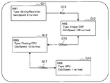
- FIG. 3 is an explanatory diagram showing an example of a constraint input screen for inputting constraints related to a plurality of hardware.
- the constraint input screen includes, for example, hardware input forms G11 to G14 indicating hardware used for recognition processing and communication speed input forms G15 to G17 indicating communication speeds between hardware.
- the user can use the hardware input forms G11 to G14 to select the type (Type) of hardware (HW: Hardware) and input hardware information (for example, computing performance).
- Type type of hardware
- HW Hardware
- input hardware information for example, computing performance
- the user can further customize the constraints by further inputting information of each hardware using the hardware input forms G11 to G14.
- the user can input (customize) the communication speed between hardware using the communication speed input forms G15 to G17.
- the connection relationship between the hardware input forms G11 to G14 may be changeable by a user operation.
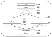
- FIG. 4 is an explanatory diagram showing an example of a design screen for designing a neural network.
- the design screen illustrated in FIG. 4 may be received from the server 2 via the communication unit 12.
- the design screen includes a plurality of layers G20 to G30 in the neural network.
- the arranged layers G20 to G30 may mean, for example, data acquisition, data processing, and data output, respectively.
- the user can design a neural network by adding, deleting, and changing a layer using a design screen as shown in FIG.
- the layers G21 to G29 between the input layer G20 and the output layer G30 may be processed sequentially or in parallel in the order in which they are arranged.
- the processing of layers G24 to G26 and the processing of layers G27 to G28 may be performed in parallel.
- control unit 10 may control the display unit 14 to perform display control processing based on the determination result received from the server 2. For example, when it is determined by the server 2 that the neural network does not satisfy the constraints related to a plurality of hardware, the control unit 10 (display control unit) may display a warning screen indicating that the constraints are not satisfied. Good.
- the warning screen displayed by the control unit 10 may be a screen that presents a portion that does not satisfy the restriction in the neural network. With such a configuration, the user can more efficiently design the neural network so as to satisfy the constraints related to a plurality of hardware.
- the communication unit 12 (reception unit) is a communication interface that is controlled by the control unit 10 and mediates communication with other devices.
- the communication unit 12 supports an arbitrary wireless communication protocol or wired communication protocol, and establishes a communication connection with another device via, for example, the communication network 5 shown in FIG.
- the communication unit 12 receives from the server 2 a design screen for designing a neural network and a determination result as to whether or not the neural network satisfies a plurality of hardware constraints.
- the communication unit 12 causes the server 2 to transmit information related to user input on various screens displayed on the display unit 14.
- the display unit 14 is a display that displays various screens under the control of the control unit 10.
- the display unit 14 may display the above-described constraint input screen, design screen, warning screen, and the like.
- the display unit 14 may be realized by, for example, a CRT (Cathode Ray Tube) display device, a liquid crystal display (LCD) device, or an OLED (Organic Light Emitting Diode) device.
- CTR Cathode Ray Tube
- LCD liquid crystal display
- OLED Organic Light Emitting Diode
- the operation unit 16 receives user input and provides it to the control unit 10. For example, the user may operate the operation unit 16 to perform input for customizing constraints related to a plurality of hardware and designing a neural network.
- the operation unit 16 may be realized by, for example, a mouse, a keyboard, a touch panel, a button, a switch, a line-of-sight input device, a gesture input device, a voice input device, or the like.
- FIG. 5 is an explanatory diagram for explaining a configuration example of the server 2 according to the present embodiment.
- the server 2 is an information processing apparatus that includes a control unit 20, a communication unit 22, and a storage unit 24.
- the control unit 20 controls each component of the server 2. Further, as illustrated in FIG. 5, the control unit 20 also functions as a communication control unit 201, an acquisition unit 202, a determination unit 203, a design control unit 204, a learning unit 205, and a recognition unit 206.
- the communication control unit 201 controls communication by the communication unit 22.
- the communication control unit 201 may control the communication unit 22 to transmit the design screen of the neural network, the determination result by the determination unit 203, and the like to the client terminal 1.
- the communication control unit 201 may control the communication unit 22 to receive information related to user input for customizing constraints related to a plurality of hardware and designing a neural network.
- the acquisition unit 202 acquires constraints related to a plurality of hardware. For example, the acquisition unit 202 may acquire a plurality of hardware restrictions from the storage unit 24. In addition, the acquisition unit 202 may acquire a plurality of hardware constraints based on a user input for customizing a plurality of hardware constraints received via the communication unit 22. Further, the acquisition unit 202 may acquire a plurality of hardware constraints based on a user input related to hardware selection and a hardware constraint stored in advance in the storage unit 24.
- constraints related to the neurochip, the CPU, and the GPU described with reference to FIG. 1 will be described, but the constraints related to the hardware are not limited to the following examples.
- Constraints related to a plurality of hardware acquired by the acquisition unit 202 may be constraints used for determination by the determination unit 203 described below, for example. Examples of the constraints used for the determination may include constraints related to connections between hardware, constraints related to communication speed between hardware, constraints related to hardware processing capability, and the like. Examples of constraints used for determination by the determination unit 203 are shown below.
- the neurochip is connected to the sensor (input layer)-The number of nodes that can be processed by the neurochip is 10 or less-The convolution layer is the only layer that can be processed by the neurochip-Between the neurochip and the CPU
- the communication speed of the CPU is a predetermined speed.
- the RAM usable by the CPU is below a predetermined value.
- the communication speed between the CPU and the GPU is a predetermined speed.
- the GPU cannot be directly connected to the neurochip.
- constraints related to the plurality of hardware acquired by the acquiring unit 202 may be constraints used for the learning unit 205 described later to perform learning according to the hardware, for example.
- constraints used to perform learning may include constraints related to hardware characteristics, constraints related to types of operations, and the like. Below, the example of the restrictions used for the learning by the learning part 205 is shown.
- the determination unit 203 determines whether the neural network satisfies a plurality of hardware restrictions acquired by the acquisition unit 202.
- the determination unit 203 determines, for example, whether the neural network designed by the design control unit 204 satisfies the above constraints based on a user input.
- the determination unit 203 determines whether the neural network satisfies a plurality of hardware constraints acquired by the acquisition unit 202 based on a predetermined processing time that is set in advance or input by the user. A determination may be made. In such a case, the determination unit 203 satisfies the constraint when it is determined that the neural network satisfies a plurality of hardware constraints acquired by the acquisition unit 202 and the processing is completed within the predetermined processing time. You may judge.
- the determination unit 203 determines that the neural network after the change is the above when the neural network is changed by the design control unit 204 based on the user input (for example, when a layer is added, deleted, or a layout is changed). It may be determined whether or not the constraint is satisfied. Note that the determination unit 203 may provide the determination result to the communication control unit 201 and the design control unit 204.
- the design control unit 204 controls the design of the neural network based on the user input acquired via the communication unit 22. For example, the design control unit 204 may generate the design screen described with reference to FIG. 4 and provide it to the client terminal 1 via the communication unit 22. The design control unit 204 may control the arrangement of layers in the neural network based on user input.
- the design control unit 204 associates the layers in the neural network with the hardware based on the user input acquired via the communication unit 22.
- the user input related to the association may be performed by range selection on the design screen of the neural network, or may be performed by specifying the order in the layer processing order.
- the design control unit 204 may create a program for constructing the neural network designed by the design control unit 204 when the determination unit 203 determines that the constraint is satisfied. According to such a configuration, a program that satisfies the constraints on a plurality of hardware and constructs a neural network that can execute recognition by the plurality of hardware is generated.
- the design control unit 204 is a layer related to the change of the neural network so that the neural network designed by the design control unit 204 satisfies the constraint when the determination unit 203 determines that the constraint is not satisfied. May be rearranged. For example, the design control unit 204 may rearrange the added layer or the rearranged layer on hardware that can communicate with the hardware currently associated with the layer. In addition, the design control unit 204 may acquire a determination result as to whether or not the rearranged neural network satisfies the constraint from the determination unit 203, and may repeat the rearrangement until the constraint is satisfied. According to such a configuration, it becomes possible to design a neural network that satisfies the constraints related to a plurality of hardware more efficiently.
- the learning unit 205 learns the neural network designed by the design control unit 204. For example, the learning unit 205 may perform learning according to the hardware associated with the layer for each layer in the neural root and the workpiece based on the constraints acquired by the acquisition unit 202. According to this configuration, the performance of recognition performed by the recognition unit 206 described later can be improved.
- the learning related to the layer associated with the neurochip may be performed by a learning method according to the characteristics of the neurochip.
- the learning method according to the characteristic of a neurochip is not limited, For example, when the characteristic of a neurochip is spiking, the learning method described in the following nonpatent literature 2 can also be used.
- Non-Patent Document 2 O. Peter, 4 others, “Real-time classification and sensor fusion with a spiking deep belief network”, 2013, Neuromorphic Engineering 7: 178.
- learning related to a layer associated with hardware capable of performing only integer operations may be performed by a learning method that enables processing by only integer operations.
- the learning method which concerns is not limited, For example, the learning method described in the following nonpatent literature 3 can also be used.
- Non-Patent Document 3 M. Courbariaux, 2 others, "BinaryConnect: Training Deep Neural Networks with binary weights during propagations TensorFlow: Large-Scale Machine Learning on Heterogeneous Distributed Systems", November 12, 2015, [Online] Search on April 21, 2016], Internet ⁇ http://arxiv.org/pdf/1511.00363.pdf>
- learning related to a layer associated with hardware capable of floating-point arithmetic can be performed by various learning methods that can use floating-point arithmetic.
- the learning unit 205 may perform learning based on learning data stored in the storage unit 24 or may perform learning based on learning data acquired from the outside via the communication unit 22.
- the recognition unit 206 performs recognition based on learning by the learning unit 205.
- the recognition unit 206 may perform recognition by performing feedforward calculation using hardware associated with each layer in the neural network. Note that the recognition unit 206 may recognize data stored in the storage unit 24 or may recognize data acquired from the outside via the communication unit 22.
- the communication unit 22 is a communication interface that mediates communication with other devices.
- the communication unit 22 supports an arbitrary wireless communication protocol or wired communication protocol, and establishes a communication connection with another device via, for example, the communication network 5 illustrated in FIG.
- the server 2 can receive a user input from the client terminal 1 connected to the communication network 5, and can transmit a design screen, a determination result by the determination unit 203, and the like to the client terminal 1. Become.
- the storage unit 24 stores a program and parameters for each component of the server 2 to function.
- the storage unit 24 may store hardware constraints, learning data, recognition data, and the like.
- the server 2 includes the learning unit 205 and the recognition unit 206 to perform learning and recognition.
- learning and recognition may be performed by other devices connected to the communication network 5, and learning and recognition may be performed by different devices.
- the acquisition unit 202 may acquire, via the communication unit 22, from the device that performs the recognition, restrictions on a plurality of hardware that the device that performs the recognition has.
- Example of operation> The configuration example of the information processing system 1000 according to the present embodiment has been described above. Subsequently, an operation example of the information processing system 1000 according to the present embodiment will be described with reference to FIGS. In the following, first, the processing flow of the information processing system 1000 will be described with reference to FIGS. 6 and 7, and examples of screen transitions displayed on the client terminal 1 in this embodiment will be described with reference to FIGS. .
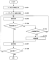
- FIG. 6 is a flowchart showing a processing flow example of the information processing system 1000 according to the present embodiment.
- the flowchart shown in FIG. 6 shows the processing flow especially related to the design of the neural network among the operations according to the present embodiment.
- the user inputs constraints related to hardware, and the acquisition unit 202 acquires the constraints (S1101).
- the range for each hardware related to the correspondence between the hardware and the layer is set by the user (S1102).
- the range setting for each hardware may be performed by selecting a display range on the design screen of the neural network, or by specifying the order in the layer processing order.
- the user designs a neural network using the neural network design screen (S1103).
- the determination unit 203 determines whether or not the designed neural network satisfies a plurality of hardware constraints (S1104).
- the determination unit 203 determines that the neural network does not satisfy the constraint (S1104: NO)
- a warning screen that presents a portion (part) that does not satisfy the constraint is displayed (S1105), and the process returns to step S1103.
- the determination unit 203 determines that the neural network satisfies the constraints (S1104: YES)
- the design process ends.
- FIG. 7 is a flowchart showing a processing flow example of the information processing system 1000 according to the present embodiment.
- the flowchart shown in FIG. 7 shows the processing flow especially related to the change in the design of the neural network among the operations according to the present embodiment.
- the processing flow described below may be a processing flow for changing the design of the neural network designed by the processing of the flowchart shown in FIG.
- the user changes the design of the neural network (for example, adding, deleting, or changing the arrangement of layers) (S1203).
- the determination unit 203 determines whether or not the changed neural network satisfies a plurality of hardware constraints (S1204).
- the design control unit 204 automatically performs rearrangement (S1206).
- the automatically rearranged neural network is displayed on the design screen (S1207).
- step S1204 If it is determined in step S1204 that the constraint is satisfied, the neural network whose design has been changed is displayed on the design screen (S1207).
- FIG. 8 to 10 are explanatory diagrams showing examples of screens displayed on the client terminal 1 according to the present embodiment. 8 to 10 are examples of screen transitions related to the design change of the neural network included in the design screen described with reference to FIG. Further, the following description will be given with reference to the processing steps shown in FIG.
- step S1201 in FIG. 7 the constraint input screen described with reference to FIG. 3 is displayed. Note that if the user does not need to change the hardware constraint, the acquisition unit 202 may acquire the constraint from the storage unit 24, for example, without user input.
- step S1202 of FIG. 7 range selection for each hardware is performed as in the design screen shown in FIG.
- the layers included in the ranges G31 to G34 shown in FIG. 8 are associated with hardware corresponding to each range by the design control unit 204.
- the ranges G31, G32, G33, and G34 shown in FIG. 8 correspond to, for example, the hardware HW1, HW2, HW4, and HW3 in FIG. 3, respectively.
- step S1203 of FIG. 7 the neural network is changed as shown in the screen of FIG.
- the layer G42 is added between the layer G41 and the layer G43.
- the layer G42 newly added in FIG. 9 is associated with HW4 because it is included in the range G33 shown in FIG.
- step S1204 in FIG. 7 a design screen including a neural network in which the layer G52 is newly added by the change is displayed in step S1207 as illustrated in FIG. .
- step S1204 in FIG. 7 a design screen including the neural network before change is displayed as shown in the screen in FIG. 4 (the display is the design screen in FIG. 4). Back to).
- Second embodiment >> The first embodiment of the present disclosure has been described above. Subsequently, a second embodiment of the present disclosure will be described.
- the second embodiment of the present disclosure generates another neural network having a different network structure based on the evaluation result of the designed neural network.
- the Pareto optimal solution related to the evaluated neural network is updated based on the generated evaluation result of the neural network. Furthermore, according to the second embodiment of the present disclosure, it is possible to search for an efficient network structure by repeatedly generating a network and updating a Pareto optimal solution.
- FIG. 11 is an explanatory diagram for describing a configuration example of the server 2-2 according to the second embodiment of the present disclosure.
- the server 2-2 is an information processing apparatus including a control unit 21, a communication unit 22, and a storage unit 24.
- the server 2-2 according to the present embodiment is different from the server 2 in FIG. 5 in that the functional configuration of the control unit 21 is partially different from the functional configuration of the control unit 20 in FIG. Note that, among the components shown in FIG. 11, the components substantially the same as the components shown in FIG. Below, the function as the determination part 213, the production
- the determination unit 213 includes an acquisition unit that is a neural network designed or changed by the design control unit 204 based on a user input. It is determined whether or not the constraint acquired by 202 is satisfied. Further, the determination unit 213 according to the present embodiment determines whether or not a neural network generated by the generation unit 217 described later satisfies a constraint acquired by the acquisition unit 202.
- the generation unit 217 has a function of generating another neural network having a different network structure from the original network. For example, the generation unit 217 generates another neural network having a different network structure from a neural network (hereinafter also referred to as a seed network) that is designed based on input from the user and determined to satisfy the constraints by the determination unit 213. May be. The generation unit 217 may generate another neural network having a different network structure from the neural network related to the Pareto optimal solution.
- a neural network hereinafter also referred to as a seed network
- the generation of the neural network by the generation unit 217 according to the present embodiment may be realized by a genetic operation including, for example, mutation or crossover (or also called crossing).
- the mutation may be a model of a gene mutation found in an organism. That is, in the present embodiment, another neural network having a different network structure can be generated by regarding each layer constituting the network as a gene and mutating the layer.
- the mutation according to the present embodiment may include at least one of layer insertion, layer deletion, layer type change, parameter change, graph branch, and graph branch delete.
- the above crossover may be a model of partial exchange of chromosomes in the mating of organisms. That is, in the information processing method according to the present disclosure, the other neural network can be generated by partially exchanging the layer configurations of the two networks.
- the method for generating a neural network according to the present embodiment is not limited to such an example.
- the generation of another neural network according to the present embodiment may be realized using, for example, a neural network that changes the network structure of the input network.
- Various methods including the above example can be applied to the generation of the neural network.
- the generation unit 217 may repeat generation of another neural network until a neural network determined to satisfy the constraint by the determination unit is generated. According to such a configuration, the generation unit 217 can generate a neural network that satisfies the constraints related to a plurality of hardware.
- the evaluation unit 218 has a function of acquiring the evaluation result of the generated neural network.
- the evaluation unit 218 may cause the recognition unit 206 to execute the generated neural network and acquire the evaluation result.
- the acquisition of the evaluation result by the evaluation unit 218 is not limited to the above, and the evaluation result may be acquired by executing a neural network generated by various devices connected via the communication network 5.
- the evaluation result acquired by the evaluation unit 218 includes at least one of a calculation amount related to the generated neural network and a learning error or a validation error (hereinafter, sometimes collectively referred to as an error). It's okay.
- the evaluation unit 218 can acquire the above calculation amount based on the network structure of the generated neural network. Note that the evaluation result according to the present embodiment is not limited to the above. For example, the total cost of hardware calculated from the amount of used memory, the amount of heat generation, the amount of power consumption, the amount of calculation, the server cost, etc.
- the total service cost including The evaluation unit 218 can calculate the above values based on information related to hardware and services stored in advance.
- the evaluation unit 218 has a function of updating the Pareto optimal solution related to the evaluated neural network based on the generated evaluation result of the neural network. In other words, the evaluation unit 218 acquires the evaluation result of the neural network generated by the generation unit 217, and repeatedly executes the update of the Pareto optimal solution based on the evaluation result.
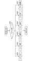
- FIG. 12 is a flowchart for explaining an operation example of the present embodiment.
- the processing in steps S2100 and S2200 shown in FIG. 7 is the same as the processing in steps S1101 and S1102 described with reference to FIG.
- step S2300 the design of the neural network by the user and the determination by the determination unit 213 are performed (S2300).
- the processing in step S2300 may include, for example, processing similar to the processing in steps S1103 to S1105 described with reference to FIG. 6 or the processing in steps S1203 to S1208 described with reference to FIG.
- the generation unit 217 generates another neural network having a different network structure from the neural network (seed network) determined to satisfy the constraint by the determination unit 213 in step S2300 (S2400).
- seed network the neural network determined to satisfy the constraint by the determination unit 213 in step S2300 (S2400).
- a detailed processing flow relating to generation of the neural network in step S2400 will be described later with reference to FIGS.
- the evaluation unit 218 acquires the evaluation result of the generated neural network (S2500). If the network structure search by the evaluation unit 218 has not been completed (S2600: NO), the process proceeds to step S2700.
- step S2700 the evaluation unit 218 updates the Pareto optimal solution related to the evaluated neural network based on the generated evaluation result of the neural network. Subsequently, the process returns to step S2400, and the generation unit 217 generates another neural network having a different network structure from the neural network related to the Pareto optimal solution.
- a neural network with a minimum error (maximum performance), a neural network with a minimum amount of calculation, or a neural network with an intermediate solution may be obtained.
- the definition of the intermediate solution may be appropriately designed according to conditions.
- the neural network as described above may be presented to the user, and the user may select one of the neural networks.
- FIG. 13 is a flowchart for explaining a processing flow relating to generation of a neural network.
- the generation unit 217 randomly determines another neural network generation method to be applied to the original neural network (S2410).
- the original neural network may be a seed network designed based on an input by the user and determined to satisfy the constraint by the determination unit 213.
- the original neural network may be a network randomly selected by the generation unit 217 from the neural network related to the Pareto optimal solution updated by the evaluation unit 218.
- the generation unit 217 generates another neural network having a different network structure from the original neural network based on the generation method selected in step S2410.
- the generation unit 217 according to the present embodiment may generate another neural network described above by mutating the original neural network (S2420).
- the generation unit 217 may generate another neural network described above by crossing the original neural network (S2430).
- S2430 The detailed flow of mutation and crossover in step S2420 and step S2430 will be described later with reference to FIGS. 14 and 15, respectively.
- the generation unit 217 determines the consistency of the neural network generated in step S2420 or step S2430 (S2440). At this time, the generation unit 217 may determine whether an error has occurred in the layer configuration of the generated neural network. The generation unit 217 may determine that there is no network consistency, for example, when the input data is too small during the Max-Pooling process. Thus, when it determines with there being no consistency of the produced
- the determination unit 213 determines whether or not the generated neural network satisfies the constraint acquired by the acquisition unit 202. If the determination unit 213 determines that the generated neural network does not satisfy the constraint (S2450: NO), the generation unit 217 discards the generated neural network and returns to step S2410.
- the generation unit 217 determines whether the input and output of the generated neural network and the original neural network are the same (S2460). .
- the generation unit 217 discards the generated neural network and returns to step S2410.
- the generation unit 217 normally ends the process related to network generation.
- the generation unit 217 according to the present embodiment can generate another neural network having a different network structure from a seed network or a network related to the Pareto optimal solution.
- FIG. 13 the case where the generation unit 217 generates another neural network by genetic operation using mutation or crossover has been described as an example.
- the generation of the network according to the present embodiment is not limited to the example.
- the generation unit 217 according to the present embodiment may generate another neural network described above using a neural network that changes the network structure of the input neural network. Various methods may be applied to the generation of the neural network by the generation unit 217.
- FIG. 14 is a flowchart for explaining network generation using mutation by the generation unit 217. That is, the flowchart shown in FIG. 14 shows the detailed control of the generation unit 217 in step S2420 shown in FIG.
- the mutation according to the present embodiment may include layer insertion, layer deletion, layer type change, parameter change, graph branch, and graph branch delete.
- the generation unit 217 randomly determines a mutation technique to be applied to the original neural network (S2421). Subsequently, the generation unit 217 changes the network structure of the original neural network based on the method selected in step S2421.
- the generation unit 217 may perform a process of inserting a new layer (S2422). For example, the generation unit 217 can generate another neural network having a different network structure by newly inserting an activation function such as Relu into the original neural network.
- the generation unit 217 may perform a process of deleting an existing layer (S2423).
- the generation unit 217 can generate another neural network having a different network structure, for example, by deleting a layer related to Max-Pooling from the original neural network.
- the generation unit 217 may perform a process of changing the layer type of the existing layer (S2424).
- the generation unit 217 can generate another neural network having a different network structure, for example, by replacing an activation function existing in the original neural network with another activation function.
- the generation unit 217 may perform a process of changing parameters related to an existing layer (S2425). For example, the generation unit 217 can generate another neural network having a different network structure by changing the kernel shape of an existing Convolution layer.
- the generation unit 217 may perform a process of creating a new graph branch (S2426). For example, the generation unit 217 can generate another neural network by creating a graph branch by copying a part of an existing layer and inserting a Concatenate layer as a connection unit of the graph branch.
- the generation unit 217 may perform a process of deleting an existing graph branch (S2427). For example, the generation unit 217 can generate another neural network by deleting one route of an existing graph branch and deleting the Concatenate layer when the branch disappears due to the deletion.
- the network generation using mutation by the generation unit 217 according to the present embodiment has been described above.
- the case where the generation unit 217 executes the processing of steps S2422 to S2427 selected at random has been described as an example.
- the mutation control according to the present embodiment is not limited to this example.
- the generation unit 217 may perform two or more processes related to steps S2422 to S2427 at the same time, or may execute execution determinations of steps S2422 to S2427. Further, the generation unit 217 may execute processing other than that shown in the example of FIG. Mutation control by the generation unit 217 can be flexibly changed.
- FIG. 15 is a flowchart for explaining network generation using crossover by the generation unit 217. That is, the flowchart shown in FIG. 15 shows the detailed control of the generation unit 217 in step S2430 shown in FIG.
- the generation unit 217 selects two original networks in order to perform crossover (S2431).
- the generation unit 217 may select two seed networks that are designed based on an input by the user and determined to satisfy the constraint by the determination unit 213.
- the generation unit 217 can also select one seed network that is designed based on an input by the user and determined to satisfy the constraint by the determination unit 213, and a crossover network that is registered in advance.
- the generation unit 217 may select another neural network generated by mutation from the seed network that is designed based on input from the user and determined to satisfy the constraint by the determination unit 213.
- the generation unit 217 crosses the two networks selected in step S2431, and generates another neural network having a different network structure (S2432). At this time, the generation unit 217 may perform crossover by various methods.
- the generation unit 217 can generate another neural network as described above, for example, by one-point crossing, two-point crossing, multi-point crossing, uniform crossing, or the like.
- the generation unit 217 according to the present embodiment can generate another neural network having a different network structure from the original neural network by a genetic operation including mutation and crossover. That is, in the information processing method according to the present embodiment, it is possible to search for a more efficient network structure by repeatedly updating the Pareto optimal solution based on the evaluation result of the neural network generated by the generation unit 217. .
- another neural network having a different network structure can be generated based on the evaluation result of the designed neural network. Further, according to the present embodiment, it is possible to search for an efficient network structure by repeatedly generating a network and updating the Pareto optimal solution.
- the generated neural network is a neural network that is determined by the determination unit 213 to satisfy a plurality of hardware constraints. Therefore, according to the present embodiment, it is possible to search for an efficient network structure that is suitable for processing by a plurality of hardware.
- the client terminal 1 has the functions of the acquisition unit 202, the determination unit 203, and the design control unit 204 described with reference to FIG. 5, and information on the neural network designed using the client terminal 1 is stored in the server. 2 may be provided.
- FIG. 16 is an explanatory diagram showing the hardware configuration of the server 2.
- the server 2 includes a CPU (Central Processing Unit) 2001, a DSP (Digital Signal Processor) 2002, a GPU (Graphics Processing Unit) 2003, a neurochip 2004, and a ROM (Read Only Only). 2005, RAM (Random Access Memory) 2006, an input device 2007, an output device 2008, a storage device 2009, a drive 2010, and a communication device 2011.
- CPU Central Processing Unit
- DSP Digital Signal Processor
- GPU Graphics Processing Unit
- ROM Read Only Only
- RAM Random Access Memory
- the CPU 2001 functions as an arithmetic processing unit and a control unit, and controls the overall operation in the server 2 according to various programs. Further, the CPU 2001 may be a microprocessor.
- the DSP 2002, GPU 2003, and neurochip 2004 function as an arithmetic processing device.
- the CPU 2001, the DSP 2002, the GPU 2003, and the neurochip 2004 may be hardware that executes recognition processing using a neural network in the present disclosure.
- the ROM 2005 stores programs used by the CPU 2001, calculation parameters, and the like.
- the RAM 2006 temporarily stores programs used in the execution of the CPU 2001, DSP 2002, GPU 2003, and neurochip 2004, parameters that change as appropriate during the execution, and the like. These are connected to each other by a host bus including a CPU bus. Mainly, the functions of the communication control unit 201, the acquisition unit 202, the determination unit 203, the design control unit 204, and the learning unit 205 are realized by the cooperation of the CPU 2001, the ROM 2005, the RAM 2006, and the software.
- the input device 2007 includes input means for a user to input information, such as a mouse, keyboard, touch panel, button, microphone, switch, and lever, and an input control circuit that generates an input signal based on the input by the user and outputs the input signal to the CPU 2001.
- a user can input various data and instruct processing operations to the server 2 by operating the input device 2007.
- the output device 2008 includes a display device such as a liquid crystal display (LCD) device, an OLED (Organic Light Emitting Diode) device, and a lamp. Furthermore, the output device 2008 includes an audio output device such as a speaker and headphones. For example, the display device displays a captured image or a generated image. On the other hand, the audio output device converts audio data or the like into audio and outputs it.
- a display device such as a liquid crystal display (LCD) device, an OLED (Organic Light Emitting Diode) device, and a lamp.
- the output device 2008 includes an audio output device such as a speaker and headphones.
- the display device displays a captured image or a generated image.
- the audio output device converts audio data or the like into audio and outputs it.
- the storage device 2009 is a data storage device configured as an example of the storage unit 24 of the server 2 according to the present embodiment.
- the storage device 2009 may include a storage medium, a recording device that records data on the storage medium, a reading device that reads data from the storage medium, a deletion device that deletes data recorded on the storage medium, and the like.
- the storage device 2009 stores programs executed by the CPU 2001 and various data.
- the drive 2010 is a reader / writer for a storage medium, and is built in the server 2 or externally attached.
- the drive 2010 reads information recorded on a removable storage medium such as a mounted magnetic disk, optical disk, magneto-optical disk, or semiconductor memory, and outputs the information to the RAM 2005.
- the drive 2010 can also write information to a removable storage medium.
- the communication device 2011 is a communication interface configured by a communication device or the like.
- the communication device 2011 may be a wireless LAN (Local Area Network) compatible communication device, an LTE (Long Term Evolution) compatible communication device, or a wire communication device that performs wired communication.
- the communication device 2011 corresponds to the communication unit 22 of the server 2.
- the client terminal 1 and the server 2-2 according to the second embodiment also have hardware equivalent to the CPU 2001, the ROM 205, the RAM 206, and the like, like the server 2.
- the function of the control part 10 is implement
- functions corresponding to the determination unit 213, the generation unit 217, and the evaluation unit 218 are realized by the cooperation of the hardware and software of the server 2-2 according to the second embodiment.
- each step in the above-described embodiment does not necessarily have to be processed in time series in the order described as a flowchart.
- each step in the processing of the above embodiment may be processed in an order different from the order described as the flowchart diagram or may be processed in parallel.
- the processing in step S1101 for inputting or obtaining hardware-related constraints and the processing in step S1102 for setting a range for each hardware are performed after the processing in step S1103 related to the design of the neural network. May be.
- the computer program for causing the hardware such as the CPU 2001, the ROM 2005, and the RAM 2006 to perform the same functions as the configurations of the client terminal 1, the server 2, and the server 2-2 described above. Can be provided.
- a recording medium on which the computer program is recorded is also provided.
- the design control unit creates a program for constructing the neural network when the determination unit determines that the constraint is satisfied.
- Processing equipment (6)
- the display unit further includes a display control unit that displays a warning screen indicating that the constraint is not satisfied.
- the information processing apparatus according to item.
- the warning screen presents a portion that does not satisfy the restriction in the neural network.
- the learning unit according to any one of (1) to (7), further including a learning unit that performs learning according to hardware associated with the layer for each layer in the neural network based on the constraint. Information processing device.
- a generating unit that generates another neural network having a different network structure from the neural network determined to satisfy the constraint by the determining unit;
- An evaluation unit that obtains an evaluation result of the generated neural network, and The evaluation unit updates the Pareto optimal solution related to the evaluated neural network based on the generated evaluation result of the neural network,
- the generation unit generates another neural network having a different network structure from the neural network related to the Pareto optimal solution.
- the information processing apparatus according to any one of (1) to (8).
- the determination unit determines whether the neural network generated by the generation unit satisfies the constraint, The information processing apparatus according to (9), wherein the generation unit repeats generation of the other neural network until a neural network determined to satisfy the constraint is generated by the determination unit.
- the information processing apparatus according to (9) or (10), wherein the generation unit generates the another neural network by a genetic operation.
- the genetic operation includes at least one of mutation and crossover.
- the mutation includes at least one of layer insertion, layer deletion, layer type change, parameter change, graph branch, or graph branch delete .
- the information processing apparatus according to any one of (1) to (13), further including a communication control unit that transmits a determination result by the determination unit.
- a receiving unit that receives a determination result of whether or not the neural network satisfies a plurality of hardware constraints;
- a processing unit for performing processing based on the determination result;
- An information processing apparatus comprising: (16) Obtaining constraints on multiple hardware; Determining whether the neural network satisfies the constraints;
- An information processing method including:
Landscapes
- Engineering & Computer Science (AREA)
- Physics & Mathematics (AREA)
- Theoretical Computer Science (AREA)
- Health & Medical Sciences (AREA)
- Life Sciences & Earth Sciences (AREA)
- Computing Systems (AREA)
- Software Systems (AREA)
- Biomedical Technology (AREA)
- Biophysics (AREA)
- General Health & Medical Sciences (AREA)
- Mathematical Physics (AREA)
- Evolutionary Computation (AREA)
- Computational Linguistics (AREA)
- Molecular Biology (AREA)
- General Engineering & Computer Science (AREA)
- General Physics & Mathematics (AREA)
- Data Mining & Analysis (AREA)
- Artificial Intelligence (AREA)
- Bioinformatics & Cheminformatics (AREA)
- Bioinformatics & Computational Biology (AREA)
- Evolutionary Biology (AREA)
- Physiology (AREA)
- Neurology (AREA)
- User Interface Of Digital Computer (AREA)
Abstract
Description
<1-1.背景>
<1-2.構成例>
<1-3.動作例>
<1-4.効果>
<<2.第二の実施形態>>
<2-1.構成例>
<2-2.動作例>
<2-3.効果>
<<3.変形例>>
<3-1.変形例1>
<3-2.変形例2>
<<4.ハードウェア構成例>>
<<5.むすび>>
<1-1.背景>
本開示の第一の実施形態に係る情報処理装置について説明する前に、まず、本実施形態の創作に至った背景を説明する。
図2を参照しながら、本開示の第一の実施形態の構成例を説明する。図2は、本開示の第一の実施形態に係る情報処理システムの構成例を説明するための説明図である。本実施形態に係る情報処理システム1000は、ユーザによるニューラルネットワークの設計のための情報処理システムであり、例えばビジュアルプログラミングにより、ニューラルネットワークを設計することが可能なツールを提供してもよい。
続いて、本実施形態に係るクライアント端末1について詳細に説明する。図2に示すように、本実施形態に係るクライアント端末1は、制御部10、通信部12、表示部14、及び操作部16を備える情報処理装置である。なお、クライアント端末1は、例えばPC(Personal Computer)、タブレットPC等であってもよい。
以上、本実施形態に係るクライアント端末1の構成例を説明した。続いて、図5を参照して、本実施形態に係るサーバ2の構成例を説明する。図5は、本実施形態に係るサーバ2の構成例を説明するための説明図である。図5に示すように、サーバ2は、制御部20、通信部22、及び記憶部24を備える情報処理装置である。
・ニューロチップが処理可能なノード数は10以下である
・ニューロチップが処理可能なレイヤーはコンボリューションレイヤーのみである
・ニューロチップとCPUとの間の通信速度は所定の速度である
・CPUが利用可能なRAMは所定値以下である
・CPUとGPUとの間の通信速度は所定の速度である
・GPUはニューロチップと直接接続できない
・CPUは整数演算のみ可能(浮動小数点演算不可能)である
以上、本実施形態による情報処理システム1000の構成例について説明した。続いて、本実施形態による情報処理システム1000の動作例について、図6~10を参照して説明する。以下では、まず情報処理システム1000の処理フローについて図6、図7を参照して説明した後、本実施形態においてクライアント端末1に表示される画面遷移例について図8~10を参照して説明する。
図6は、本実施形態による情報処理システム1000の処理フロー例を示すフローチャート図である。図6に示すフローチャートは、本実施形態に係る動作のうち、特にニューラルネットワークの設計に係る処理フローを示す。
図7は、本実施形態による情報処理システム1000の処理フロー例を示すフローチャート図である。図7に示すフローチャートは、本実施形態に係る動作のうち、特にニューラルネットワークの設計の変更に係る処理フローを示す。例えば以下に説明する処理フローは、図6に示したフローチャートの処理により設計されたニューラルネットワークの設計を変更する際の処理フローであってもよい。
以上、本実施形態による情報処理システム1000の処理フローを説明した。続いて、図7を参照して説明した処理フローにおいて、クライアント端末1に表示される画面の遷移例を図3、4及び図8~10を参照して説明する。図8~10は、本実施形態に係るクライアント端末1に表示される画面例を示す説明図である。なお、図8~10は図4を参照して説明した設計画面に含まれるニューラルネットワークの設計変更に係る画面遷移の一例である。また、以下では、図7に示した処理ステップを適宜参照しながら説明を行う。
以上説明したように、本開示の第一の実施形態によれば、複数のハードウェアに係る制約に基づき、ニューラルネットワークが当該制約を満たすか否かを判定し、例えばユーザに判定結果に基づく警告画面を提供する。係る構成により、複数のハードウェアによる処理に適合したニューラルネットワークをより効率的に設計することが可能である。また、本実施形態によれば、変更されたニューラルネットワークが当該制約を満たさない場合には、制約を満たすように自動的に再配置が行われることで、制約を満たしたニューラルネットワークの設計を支援することが可能である。
以上、本開示の第一の実施形態を説明した。続いて、本開示の第二の実施形態を説明する。本開示の第二の実施形態は、設計されたニューラルネットワークの評価結果に基づいて、ネットワーク構造の異なる別のニューラルネットワークを生成する。また、本開示の第二の実施形態は、生成されたニューラルネットワークの評価結果に基づいて、評価済のニューラルネットワークに係るパレート最適解を更新する。さらに、本開示の第二の実施形態は、ネットワークの生成とパレート最適解の更新を繰り返すことで、効率の良いネットワーク構造を探索することが可能である。
図11は、本開示の第二の実施形態に係るサーバ2-2の構成例を説明するための説明図である。図11に示すように、サーバ2-2は、制御部21、通信部22、及び記憶部24を備える情報処理装置である。図11に示すように、本実施形態に係るサーバ2―2は、制御部21の機能構成が図5の制御部20の機能構成と一部異なる点で、図5のサーバ2と異なる。なお、図11に示す各構成のうち、図5に示した各構成と実質的に同様の構成については同一の符号を付してあるため、説明を省略する。以下では、本実施形態に係る制御部21が有する判定部213、生成部217、及び評価部218、としての機能について説明する。
以上、本実施形態に係るサーバ2-2の構成例について説明した。続いて、本実施形態の動作例について、図12~15を参照して説明する。
以上説明したように、本開示の第二の実施形態によれば、設計されたニューラルネットワークの評価結果に基づいて、ネットワーク構造の異なる別のニューラルネットワークを生成することができる。また、本実施形態は、ネットワークの生成と、パレート最適解の更新を繰り返すことで、効率の良いネットワーク構造を探索することが可能である。また、本実施形態において、生成されるニューラルネットワークは、判定部213により、複数のハードウェアに係る制約を満たすと判定されたニューラルネットワークである。したがって、本実施形態によれば、複数のハードウェアによる処理に適合し、かつ効率の良いネットワーク構造を探索することが可能である。
以上、本開示の実施形態を説明した。以下では、本開示に係る幾つかの変形例を説明する。なお、以下に説明する各変形例は、単独で各実施形態に適用されてもよいし、組み合わせで各実施形態に適用されてもよい。また、各変形例は、上記実施形態で説明した構成に代えて適用されてもよいし、上記実施形態で説明した構成に対して追加的に適用されてもよい。
上記実施形態ではビジュアルプログラミングによりニューラルネットワークの設計が行われる例を説明したが、本技術は係る例に限定されない。例えば、本技術に係るニューラルネットワークの設計は、テキストによるプログラミングや、CUI(Command User Interface)上の操作により行われてもよい。また、ハードウェアに係る制約や、ハードウェアとレイヤーの対応付けも、上記で説明された例に限定されず、テキスト、またはCUIにより入力されてもよい。
また、上記実施形態では、図2、図5、及び図11を参照してクライアント端末1、サーバ2、及びサーバ2-2が有する機能を説明したが、本技術は係る例に限定されない。上記実施形態で説明したクライアント端末1の機能をサーバ2、またはサーバ2-2が有してもよいし、上記実施形態で説明したサーバ2、またはサーバ2-2の機能をクライアント端末1が有してもよい。
以上、本開示の各実施形態を説明した。上述した表示制御処理、通信制御処理、取得処理、判定処理、設計制御処理、学習処理、認識処理、ネットワーク生成処理、評価結果取得処理等の情報処理は、ソフトウェアと、クライアント端末1、サーバ2、2-2との協働により実現される。以下では、本実施形態に係るサーバ2のハードウェア構成例について説明する。
以上、説明したように、本開示の実施形態によれば、複数のハードウェアによる処理に適合したニューラルネットワークをより効率的に設計することが可能である。
(1)
複数のハードウェアに係る制約を取得する取得部と、
ニューラルネットワークが、前記制約を満たすか否か判定を行う判定部と、
を備える情報処理装置。
(2)
ユーザの入力に基づく前記ニューラルネットワークの設計を制御する設計制御部をさらに備える、前記(1)に記載の情報処理装置。
(3)
前記判定部は、前記設計制御部により前記ニューラルネットワークが変更された場合に、前記判定を行う、前記(2)に記載の情報処理装置。
(4)
前記設計制御部は、前記判定部により、前記制約を満たさないと判定された場合に、前記制約を満たすように、前記変更に係るレイヤーの再配置を行う、前記(3)に記載の情報処理装置。
(5)
前記設計制御部は、前記判定部により、前記制約を満たすと判定された場合に、前記ニューラルネットワークを構築するプログラムを作成する、前記(2)~(4)のいずれか一項に記載の情報処理装置。
(6)
前記判定部により、前記制約を満たさないと判定された場合に、前記制約が満たされないことを示す警告画面を表示させる、表示制御部をさらに備える、前記(1)~(5)のいずれか一項に記載の情報処理装置。
(7)
前記警告画面は、前記ニューラルネットワークにおいて、前記制約を満たない部分を提示する、前記(6)に記載の情報処理装置。
(8)
前記制約に基づいて、前記ニューラルネットワークにおけるレイヤーごとに、前記レイヤーに対応付けられたハードウェアに応じた学習を行う学習部をさらに備える、前記(1)~(7)のいずれか一項に記載の情報処理装置。
(9)
前記判定部により前記制約を満たすと判定されたニューラルネットワークから、ネットワーク構造の異なる別のニューラルネットワークを生成する生成部と、
生成されたニューラルネットワークの評価結果を取得する評価部と、をさらに備え、
前記評価部は、生成されたニューラルネットワークの評価結果に基づいて、評価済のニューラルネットワークに係るパレート最適解を更新し、
前記生成部は、前記パレート最適解に係るニューラルネットワークから、ネットワーク構造の異なる別のニューラルネットワークを生成する、
前記(1)~(8)のいずれか一項に記載の情報処理装置。
(10)
前記判定部は、前記生成部により生成されるニューラルネットワークが、前記制約を満たすか否か判定を行い、
前記生成部は、前記判定部により前記制約を満たすと判定されたニューラルネットワークが生成されるまで、前記別のニューラルネットワークの生成を繰り返す、前記(9)に記載の情報処理装置。
(11)
前記生成部は、遺伝的操作により、前記別のニューラルネットワークを生成する、前記(9)または(10)に記載の情報処理装置。
(12)
前記遺伝的操作は、突然変異または交叉のうち少なくとも一方を含む、前記(11)に記載の情報処理装置。
(13)
前記突然変異は、レイヤーの挿入、レイヤーの削除、レイヤー種類の変更、パラメータの変更、グラフ分岐、またはグラフ分岐の削除のうち少なくともいずれか一つを含む、前記(12)に記載の情報処理装置。
(14)
前記情報処理装置は、前記判定部による判定結果を送信させる通信制御部をさらに備える、前記(1)~(13)のいずれか一項に記載の情報処理装置。
(15)
ニューラルネットワークが複数のハードウェアに係る制約を満たすか否かの判定結果を受信する受信部と、
前記判定結果に基づいて処理を行う処理部と、
を備える情報処理装置。
(16)
複数のハードウェアに係る制約を取得することと、
ニューラルネットワークが、前記制約を満たすか否か判定を行うことと、
を含む情報処理方法。
2、2-2 サーバ
5 通信網
10 制御部
12 通信部
14 表示部
16 操作部
20、21 制御部
22 通信部
24 記憶部
201 通信制御部
202 取得部
203、213 判定部
204 設計制御部
205 学習部
206 認識部
217 生成部
218 評価部
1000 情報処理システム
Claims (16)
- 複数のハードウェアに係る制約を取得する取得部と、
ニューラルネットワークが、前記制約を満たすか否か判定を行う判定部と、
を備える情報処理装置。 - ユーザの入力に基づく前記ニューラルネットワークの設計を制御する設計制御部をさらに備える、請求項1に記載の情報処理装置。
- 前記判定部は、前記設計制御部により前記ニューラルネットワークが変更された場合に、前記判定を行う、請求項2に記載の情報処理装置。
- 前記設計制御部は、前記判定部により、前記制約を満たさないと判定された場合に、前記制約を満たすように、前記変更に係るレイヤーの再配置を行う、請求項3に記載の情報処理装置。
- 前記設計制御部は、前記判定部により、前記制約を満たすと判定された場合に、前記ニューラルネットワークを構築するプログラムを作成する、請求項2に記載の情報処理装置。
- 前記判定部により、前記制約を満たさないと判定された場合に、前記制約が満たされないことを示す警告画面を表示させる、表示制御部をさらに備える、請求項1に記載の情報処理装置。
- 前記警告画面は、前記ニューラルネットワークにおいて、前記制約を満たない部分を提示する、請求項6に記載の情報処理装置。
- 前記制約に基づいて、前記ニューラルネットワークにおけるレイヤーごとに、前記レイヤーに対応付けられたハードウェアに応じた学習を行う学習部をさらに備える、請求項1に記載の情報処理装置。
- 前記判定部により前記制約を満たすと判定されたニューラルネットワークから、ネットワーク構造の異なる別のニューラルネットワークを生成する生成部と、
生成されたニューラルネットワークの評価結果を取得する評価部と、をさらに備え、
前記評価部は、生成されたニューラルネットワークの評価結果に基づいて、評価済のニューラルネットワークに係るパレート最適解を更新し、
前記生成部は、前記パレート最適解に係るニューラルネットワークから、ネットワーク構造の異なる別のニューラルネットワークを生成する、
請求項1に記載の情報処理装置。 - 前記判定部は、前記生成部により生成されるニューラルネットワークが、前記制約を満たすか否か判定を行い、
前記生成部は、前記判定部により前記制約を満たすと判定されたニューラルネットワークが生成されるまで、前記別のニューラルネットワークの生成を繰り返す、請求項9に記載の情報処理装置。 - 前記生成部は、遺伝的操作により、前記別のニューラルネットワークを生成する、請求項9に記載の情報処理装置。
- 前記遺伝的操作は、突然変異または交叉のうち少なくとも一方を含む、請求項11に記載の情報処理装置。
- 前記突然変異は、レイヤーの挿入、レイヤーの削除、レイヤー種類の変更、パラメータの変更、グラフ分岐、またはグラフ分岐の削除のうち少なくともいずれか一つを含む、請求項12に記載の情報処理装置。
- 前記情報処理装置は、前記判定部による判定結果を送信させる通信制御部をさらに備える、請求項1に記載の情報処理装置。
- ニューラルネットワークが複数のハードウェアに係る制約を満たすか否かの判定結果を受信する受信部と、
前記判定結果に基づいて処理を行う処理部と、
を備える情報処理装置。 - 複数のハードウェアに係る制約を取得することと、
ニューラルネットワークが、前記制約を満たすか否か判定を行うことと、
を含む情報処理方法。
Priority Applications (4)
| Application Number | Priority Date | Filing Date | Title |
|---|---|---|---|
| EP17789087.8A EP3451237A4 (en) | 2016-04-28 | 2017-03-07 | INFORMATION PROCESSING DEVICE AND INFORMATION PROCESSING METHOD |
| US16/080,475 US20190057309A1 (en) | 2016-04-28 | 2017-03-07 | Information processing apparatus and information processing method |
| JP2018514172A JP6996497B2 (ja) | 2016-04-28 | 2017-03-07 | 情報処理装置、及び情報処理方法 |
| US19/333,985 US20260017521A1 (en) | 2016-04-28 | 2025-09-19 | Information processing apparatus and information processing method |
Applications Claiming Priority (2)
| Application Number | Priority Date | Filing Date | Title |
|---|---|---|---|
| JP2016-091418 | 2016-04-28 | ||
| JP2016091418 | 2016-04-28 |
Related Child Applications (2)
| Application Number | Title | Priority Date | Filing Date |
|---|---|---|---|
| US16/080,475 A-371-Of-International US20190057309A1 (en) | 2016-04-28 | 2017-03-07 | Information processing apparatus and information processing method |
| US19/333,985 Continuation US20260017521A1 (en) | 2016-04-28 | 2025-09-19 | Information processing apparatus and information processing method |
Publications (1)
| Publication Number | Publication Date |
|---|---|
| WO2017187798A1 true WO2017187798A1 (ja) | 2017-11-02 |
Family
ID=60161587
Family Applications (1)
| Application Number | Title | Priority Date | Filing Date |
|---|---|---|---|
| PCT/JP2017/008988 Ceased WO2017187798A1 (ja) | 2016-04-28 | 2017-03-07 | 情報処理装置、及び情報処理方法 |
Country Status (4)
| Country | Link |
|---|---|
| US (2) | US20190057309A1 (ja) |
| EP (1) | EP3451237A4 (ja) |
| JP (1) | JP6996497B2 (ja) |
| WO (1) | WO2017187798A1 (ja) |
Cited By (9)
| Publication number | Priority date | Publication date | Assignee | Title |
|---|---|---|---|---|
| CN109800886A (zh) * | 2017-11-17 | 2019-05-24 | 松下知识产权经营株式会社 | 信息处理方法以及信息处理系统 |
| JP2019096285A (ja) * | 2017-11-17 | 2019-06-20 | パナソニックIpマネジメント株式会社 | 情報処理方法および情報処理システム |
| WO2019187542A1 (ja) * | 2018-03-28 | 2019-10-03 | ソニー株式会社 | 情報処理方法、情報処理装置、およびプログラム |
| WO2019216404A1 (ja) * | 2018-05-10 | 2019-11-14 | パナソニックIpマネジメント株式会社 | ニューラルネットワーク構築装置、情報処理装置、ニューラルネットワーク構築方法及びプログラム |
| WO2019230254A1 (ja) * | 2018-05-31 | 2019-12-05 | ソニー株式会社 | 情報処理装置、情報処理方法およびプログラム |
| CN111868754A (zh) * | 2018-03-23 | 2020-10-30 | 索尼公司 | 信息处理装置和信息处理方法 |
| JP2021039640A (ja) * | 2019-09-05 | 2021-03-11 | 株式会社東芝 | 学習装置、学習システム、および学習方法 |
| WO2021079763A1 (ja) * | 2019-10-21 | 2021-04-29 | ソニー株式会社 | 情報処理方法、情報処理装置、及びプログラム |
| JPWO2020188658A1 (ja) * | 2019-03-15 | 2021-09-13 | 三菱電機株式会社 | アーキテクチャ推定装置、アーキテクチャ推定方法、およびアーキテクチャ推定プログラム |
Families Citing this family (8)
| Publication number | Priority date | Publication date | Assignee | Title |
|---|---|---|---|---|
| JP6720402B2 (ja) * | 2017-03-21 | 2020-07-08 | 株式会社Preferred Networks | サーバ装置、学習済モデル提供プログラム、学習済モデル提供方法及び学習済モデル提供システム |
| US12050991B1 (en) * | 2018-05-21 | 2024-07-30 | Google Llc | Connectomics-based neural architecture search |
| CN112884118A (zh) * | 2019-11-30 | 2021-06-01 | 华为技术有限公司 | 神经网络的搜索方法、装置及设备 |
| JP7475164B2 (ja) * | 2020-03-05 | 2024-04-26 | キヤノン株式会社 | 情報処理装置、情報処理方法およびプログラム |
| TWI900601B (zh) * | 2021-01-15 | 2025-10-11 | 美商谷歌有限責任公司 | 用於硬體加速器之神經架構縮放之電腦實施方法、系統及非暫時性電腦可讀儲存媒體 |
| CN114969636B (zh) * | 2021-03-23 | 2023-10-03 | 华为技术有限公司 | 一种模型推荐的方法、装置和计算机设备 |
| CN113033784A (zh) * | 2021-04-18 | 2021-06-25 | 沈阳雅译网络技术有限公司 | 一种针对cpu和gpu设备搜索神经网络结构的方法 |
| CN115438767B (zh) * | 2021-06-02 | 2025-12-12 | 杭州海康威视数字技术股份有限公司 | 神经网络模型的配置确定方法、装置、设备及存储介质 |
Citations (3)
| Publication number | Priority date | Publication date | Assignee | Title |
|---|---|---|---|---|
| JPH03237557A (ja) * | 1990-02-14 | 1991-10-23 | Oki Electric Ind Co Ltd | ニューラルネットワークシミュレータ及び計算機システム |
| JPH1091676A (ja) * | 1996-07-25 | 1998-04-10 | Toyota Motor Corp | 安定化設計方法及び安定化設計プログラムを記録した記録媒体 |
| US20080319933A1 (en) * | 2006-12-08 | 2008-12-25 | Medhat Moussa | Architecture, system and method for artificial neural network implementation |
Family Cites Families (4)
| Publication number | Priority date | Publication date | Assignee | Title |
|---|---|---|---|---|
| US5812993A (en) * | 1996-03-07 | 1998-09-22 | Technion Research And Development Foundation Ltd. | Digital hardware architecture for realizing neural network |
| US8225074B2 (en) * | 2008-10-02 | 2012-07-17 | Nec Laboratories America, Inc. | Methods and systems for managing computations on a hybrid computing platform including a parallel accelerator |
| CN103678002A (zh) * | 2013-12-09 | 2014-03-26 | 华为技术有限公司 | 资源复用的控制方法和装置 |
| US10769517B2 (en) * | 2016-03-05 | 2020-09-08 | Fujitsu Limited | Neural network analysis |
-
2017
- 2017-03-07 US US16/080,475 patent/US20190057309A1/en active Pending
- 2017-03-07 EP EP17789087.8A patent/EP3451237A4/en not_active Ceased
- 2017-03-07 JP JP2018514172A patent/JP6996497B2/ja active Active
- 2017-03-07 WO PCT/JP2017/008988 patent/WO2017187798A1/ja not_active Ceased
-
2025
- 2025-09-19 US US19/333,985 patent/US20260017521A1/en active Pending
Patent Citations (3)
| Publication number | Priority date | Publication date | Assignee | Title |
|---|---|---|---|---|
| JPH03237557A (ja) * | 1990-02-14 | 1991-10-23 | Oki Electric Ind Co Ltd | ニューラルネットワークシミュレータ及び計算機システム |
| JPH1091676A (ja) * | 1996-07-25 | 1998-04-10 | Toyota Motor Corp | 安定化設計方法及び安定化設計プログラムを記録した記録媒体 |
| US20080319933A1 (en) * | 2006-12-08 | 2008-12-25 | Medhat Moussa | Architecture, system and method for artificial neural network implementation |
Non-Patent Citations (3)
| Title |
|---|
| JIN, YAOCHU ET AL.: "Neural network regularization and ensembling using multi-objective evolutionary algorithms", PROCEEDINGS OF THE 2004 CONGRESS ON EVOLUTIONARY COMPUTATION, 23 June 2004 (2004-06-23), pages 1 - 8, XP010720884 * |
| RYU KATAYAMA ET AL.: "A Comparative Analysis of Fuzzy Model and Neural Network Model by Plural Performance Indices", JOURNAL OF JAPAN SOCIETY FOR FUZZY THEORY AND SYSTEMS, vol. 4, no. 5, 31 October 1992 (1992-10-31), pages 942 - 957, XP055434320 * |
| See also references of EP3451237A4 * |
Cited By (20)
| Publication number | Priority date | Publication date | Assignee | Title |
|---|---|---|---|---|
| US11270228B2 (en) | 2017-11-17 | 2022-03-08 | Panasonic Intellectual Property Management Co., Ltd. | Information processing method and information processing system |
| JP2019096285A (ja) * | 2017-11-17 | 2019-06-20 | パナソニックIpマネジメント株式会社 | 情報処理方法および情報処理システム |
| CN109800886B (zh) * | 2017-11-17 | 2024-04-26 | 松下知识产权经营株式会社 | 信息处理方法以及信息处理系统 |
| CN109800886A (zh) * | 2017-11-17 | 2019-05-24 | 松下知识产权经营株式会社 | 信息处理方法以及信息处理系统 |
| JP7065368B2 (ja) | 2017-11-17 | 2022-05-12 | パナソニックIpマネジメント株式会社 | 情報処理方法および情報処理システム |
| US11768979B2 (en) | 2018-03-23 | 2023-09-26 | Sony Corporation | Information processing device and information processing method |
| CN111868754A (zh) * | 2018-03-23 | 2020-10-30 | 索尼公司 | 信息处理装置和信息处理方法 |
| EP3770775A4 (en) * | 2018-03-23 | 2021-06-02 | Sony Corporation | INFORMATION PROCESSING DEVICE AND INFORMATION PROCESSING METHOD |
| WO2019187542A1 (ja) * | 2018-03-28 | 2019-10-03 | ソニー株式会社 | 情報処理方法、情報処理装置、およびプログラム |
| JP7279705B2 (ja) | 2018-03-28 | 2023-05-23 | ソニーグループ株式会社 | 情報処理方法、情報処理装置、およびプログラム |
| JPWO2019187542A1 (ja) * | 2018-03-28 | 2021-04-15 | ソニー株式会社 | 情報処理方法、情報処理装置、およびプログラム |
| EP3779798A4 (en) * | 2018-03-28 | 2021-07-28 | Sony Group Corporation | INFORMATION PROCESSING METHOD, INFORMATION PROCESSING DEVICE AND PROGRAM |
| JPWO2019216404A1 (ja) * | 2018-05-10 | 2020-10-22 | パナソニックセミコンダクターソリューションズ株式会社 | ニューラルネットワーク構築装置、情報処理装置、ニューラルネットワーク構築方法及びプログラム |
| WO2019216404A1 (ja) * | 2018-05-10 | 2019-11-14 | パナソニックIpマネジメント株式会社 | ニューラルネットワーク構築装置、情報処理装置、ニューラルネットワーク構築方法及びプログラム |
| WO2019230254A1 (ja) * | 2018-05-31 | 2019-12-05 | ソニー株式会社 | 情報処理装置、情報処理方法およびプログラム |
| JPWO2020188658A1 (ja) * | 2019-03-15 | 2021-09-13 | 三菱電機株式会社 | アーキテクチャ推定装置、アーキテクチャ推定方法、およびアーキテクチャ推定プログラム |
| JP7111671B2 (ja) | 2019-09-05 | 2022-08-02 | 株式会社東芝 | 学習装置、学習システム、および学習方法 |
| JP2021039640A (ja) * | 2019-09-05 | 2021-03-11 | 株式会社東芝 | 学習装置、学習システム、および学習方法 |
| US11704570B2 (en) | 2019-09-05 | 2023-07-18 | Kabushiki Kaisha Toshiba | Learning device, learning system, and learning method |
| WO2021079763A1 (ja) * | 2019-10-21 | 2021-04-29 | ソニー株式会社 | 情報処理方法、情報処理装置、及びプログラム |
Also Published As
| Publication number | Publication date |
|---|---|
| US20260017521A1 (en) | 2026-01-15 |
| JPWO2017187798A1 (ja) | 2019-03-07 |
| JP6996497B2 (ja) | 2022-01-17 |
| US20190057309A1 (en) | 2019-02-21 |
| EP3451237A4 (en) | 2019-04-17 |
| EP3451237A1 (en) | 2019-03-06 |
Similar Documents
| Publication | Publication Date | Title |
|---|---|---|
| WO2017187798A1 (ja) | 情報処理装置、及び情報処理方法 | |
| JP6852748B2 (ja) | 情報処理方法および情報処理装置 | |
| JP2019164839A (ja) | 情報処理方法および情報処理装置 | |
| CN106471526B (zh) | 用于处理图像的方法和系统 | |
| US20150220311A1 (en) | Computer implemented modeling system and method | |
| CN110968943A (zh) | 一种终端界面的显示方法及装置 | |
| Nguyen et al. | People-centric evolutionary system for dynamic production scheduling | |
| TW201329788A (zh) | 適應性調整虛擬按鍵尺寸的方法及其顯示裝置 | |
| CN114570022B (zh) | 游戏资源处理方法、装置、设备及存储介质 | |
| CN108057249A (zh) | 一种业务数据处理方法和装置 | |
| Engert et al. | STRAIDE: a research platform for shape-changing spatial displays based on actuated strings | |
| KR102592108B1 (ko) | 동적 발광 패턴을 이용한 공연 연출 시뮬레이션 제공 시스템, 장치, 방법 및 프로그램 | |
| CN109446171A (zh) | 一种数据处理方法和装置 | |
| KR20220090695A (ko) | 강화 학습 기반 인테리어 서비스의 사물 배치 모델 제공 장치 및 방법 | |
| Reyna et al. | A reinforcement learning approach for scheduling problems | |
| CN112464497B (zh) | 基于分布式系统的故障演练方法、装置、设备及介质 | |
| KR102601286B1 (ko) | 조명 제어 장치, 방법 및 프로그램 | |
| JP6223866B2 (ja) | 表示情報生成装置、プログラム実行状況表示システム、方法およびプログラム | |
| JP7279705B2 (ja) | 情報処理方法、情報処理装置、およびプログラム | |
| KR20160052027A (ko) | 관제 맵 기반 다이어그램 생성 방법 및 그 장치 | |
| CN108108430A (zh) | 一种基于Unity3D知识森林虚拟现实系统实现的方法 | |
| JP6314717B2 (ja) | ラダープログラム作成装置、モニタリング装置、コンピュータプログラム及び機器制御装置 | |
| JP6268322B1 (ja) | 学習データ精度可視化システム、学習データ精度可視化方法、及びプログラム | |
| WO2023153491A1 (ja) | プロセス実行システム、データ構造、およびプロセス実行プログラム | |
| Gu et al. | Knowpc: Knowledge-driven programmatic reinforcement learning for zero-shot coordination |
Legal Events
| Date | Code | Title | Description |
|---|---|---|---|
| WWE | Wipo information: entry into national phase |
Ref document number: 2018514172 Country of ref document: JP |
|
| NENP | Non-entry into the national phase |
Ref country code: DE |
|
| 121 | Ep: the epo has been informed by wipo that ep was designated in this application |
Ref document number: 17789087 Country of ref document: EP Kind code of ref document: A1 |
|
| WWE | Wipo information: entry into national phase |
Ref document number: 2017789087 Country of ref document: EP |
|
| ENP | Entry into the national phase |
Ref document number: 2017789087 Country of ref document: EP Effective date: 20181128 |