WO2017187825A1 - Garniture pour véhicules - Google Patents
Garniture pour véhicules Download PDFInfo
- Publication number
- WO2017187825A1 WO2017187825A1 PCT/JP2017/010358 JP2017010358W WO2017187825A1 WO 2017187825 A1 WO2017187825 A1 WO 2017187825A1 JP 2017010358 W JP2017010358 W JP 2017010358W WO 2017187825 A1 WO2017187825 A1 WO 2017187825A1
- Authority
- WO
- WIPO (PCT)
- Prior art keywords
- glass plate
- vehicle
- garnish
- wall portion
- side wall
- Prior art date
- Legal status (The legal status is an assumption and is not a legal conclusion. Google has not performed a legal analysis and makes no representation as to the accuracy of the status listed.)
- Ceased
Links
Images







Classifications
-
- B—PERFORMING OPERATIONS; TRANSPORTING
- B60—VEHICLES IN GENERAL
- B60J—WINDOWS, WINDSCREENS, NON-FIXED ROOFS, DOORS, OR SIMILAR DEVICES FOR VEHICLES; REMOVABLE EXTERNAL PROTECTIVE COVERINGS SPECIALLY ADAPTED FOR VEHICLES
- B60J1/00—Windows; Windscreens; Accessories therefor
- B60J1/08—Windows; Windscreens; Accessories therefor arranged at vehicle sides
- B60J1/10—Windows; Windscreens; Accessories therefor arranged at vehicle sides fixedly mounted
Definitions
- the present invention relates to a garnish for a vehicle.
- a garnish may be attached to the edge of the glass plate in order to protect the edge of the glass plate that is mounted on a car window or the like and improve the appearance of the vehicle body.
- Patent Document 1 proposes a garnish that can be used in this way.
- FIG. 1 schematically illustrates a scene in which a glass plate 910 to which a conventional garnish 900 is attached is fixed to a vehicle body 920.
- a conventional garnish 900 includes an outer wall portion 902 arranged on the outer side of the vehicle, an inner wall portion 903 arranged on the inner side of the vehicle, an outer wall portion 902, and an inner wall portion 903. It has the groove part 901 comprised by the bottom wall part 904 to connect.
- the width of the groove 901 (length in the vertical direction in the figure), that is, the distance between the inner surface of the vehicle outer wall portion 902 and the inner surface of the vehicle inner wall portion 903 substantially matches the thickness of the glass plate 910.
- the groove part 901 is comprised so that the edge part of the said glass plate 910 can be clamped by inserting the edge part of the glass plate 910 in the groove part 901.
- the glass plate 910 to which such a garnish 900 is attached is fixed to the vehicle body 920 as follows, for example. That is, in the general glass plate 910, the shielding layer 911 made of ceramic is laminated on the peripheral portion of the inner surface including the end side to which the garnish 900 is attached. Since the adhesive is difficult to fix on the shielding layer 911, first, a primer 930 for facilitating fixing of the adhesive is applied to a region on the shielding layer 911 on the inner side in the plane direction from the garnish 900.
- a urethane-based adhesive 931 is applied to the region where the primer 930 is applied. And after aligning the glass plate 910 and the vehicle body 920, the area
- the inventors of the present invention have found that the following problems occur with the conventional garnish attached in this way. That is, when the glass plate is fixed to the vehicle body, a sufficient amount of primer 930 is applied in the vicinity of the vehicle interior side wall portion 903. Therefore, before the primer 930 is dried, the primer 930 may flow out toward the garnish 900 and may penetrate into a minute gap between the glass plate 910 and the vehicle interior side wall portion 903.
- the primer 930 can be firmly fixed on both the shielding layer 911 and the inner surface of the vehicle interior side wall portion 903. Moreover, when the primer 930 is cured, it becomes harder than a double-sided tape or the like, and has almost no elasticity. Therefore, when the primer 930 that has penetrated into the gap between the glass plate 910 and the vehicle interior wall 903 is cured, the shielding layer 911 of the glass plate 910 and the inner surface of the vehicle interior wall 903 are firmly bonded by the cured primer 930. End up. That is, the shielding layer 911 of the glass plate 910 and the inner surface of the vehicle interior side wall 903 cannot be displaced at all.
- the present invention has been made in consideration of such points, and an object thereof is to provide a technique that makes it difficult to cause obstacles such as peeling of a shielding layer and breakage of a garnish.
- the present invention adopts the following configuration in order to solve the above-described problems.
- a vehicle garnish according to one aspect of the present invention is a vehicle garnish that sandwiches an edge of a glass plate attached to a vehicle window, the vehicle outer wall portion disposed on the vehicle outer side, and the vehicle The vehicle inner wall portion disposed so as to face the outer wall portion, and the rear side in the insertion direction of the glass plate are connected to one end portions of the vehicle outer wall portion and the vehicle inner wall portion, and the vehicle An outer wall portion and an inner wall portion of the vehicle, and a bottom wall portion that constitutes a groove portion that sandwiches an end side of the glass plate to be inserted.
- the said vehicle interior side wall part is arrange
- the front end side region of the vehicle interior side wall that forms the groove into which the end of the glass plate is inserted is separated from the glass plate in the direction perpendicular to the surface. Therefore, a shielding layer made of ceramic is formed on the peripheral edge of the inner surface of the glass plate, and even if a primer is applied on the shielding layer, the primer flowing into the groove portion of the garnish Fixing to both the shielding layer and the surface of the tip side region can be suppressed. Therefore, it is possible to reduce the possibility that the shielding layer of the glass plate and the inner side wall of the garnish are firmly adhered by the primer, thereby making it difficult to cause obstacles such as peeling of the shielding layer and breakage of the garnish. be able to.
- the front end side region may extend from the end of the vehicle outer side wall portion toward the front side in the insertion direction of the glass plate, and the front end side region
- the double-sided tape for bonding the said glass plate and the said vehicle interior side wall part may be arrange
- the inner wall portion of the vehicle in the insertion direction of the glass plate, the inner wall portion of the vehicle is longer than the outer wall portion of the vehicle, and a double-sided tape is disposed in the front end side region of the inner wall portion of the vehicle that protrudes from the end of the outer wall portion of the vehicle.
- the double-sided tape can be affixed to the vehicle inner wall without interference from the vehicle outer wall, thereby facilitating the work of attaching the garnish to the edge of the glass plate.
- the thickness of the double-sided tape may be larger than the distance in the perpendicular direction between the sandwiched glass plate and the tip side region. Good. According to the said structure, since the thickness of a double-sided tape is thicker than the clearance gap formed between a glass plate and the front end side area
- the corner on the near side of the glass plate in the insertion direction of the glass inner wall may be rounded. If the corner on the front side of the glass plate on the inner wall of the car is square, when peeling the release paper on the double-sided tape, a part of the release paper will be removed before the release paper is completely removed from the double-sided tape. There is a possibility of being cut by the corner. Thereby, the efficiency of the operation
- angular side near the insertion direction of the glass plate of a vehicle inner side wall part is rounded, it can prevent that a part of release paper cuts off by this corner
- the release paper can be smoothly peeled off from the double-sided tape. Therefore, the efficiency of the operation
- the distance between the inner wall portion of the vehicle and the sandwiched glass plate is larger on the front side than the back side in the insertion direction of the glass plate. It may be.
- the primer applied to the shielding layer of the glass plate flows into the garnish from the near side in the insertion direction. Therefore, by increasing the distance between the vehicle interior side wall portion and the glass plate on the front side of the back side in the insertion direction of the glass plate, the primer that has flowed in both the shielding layer of the glass plate and the surface of the tip side region Can be further suppressed.
- the support region may be configured by one or a plurality of ribs that protrude from the inner surface of the vehicle interior side wall portion and support the end side of the glass plate.
- a through-hole penetrating in the thickness direction may be provided on the inner side of the inner wall of the vehicle in the insertion direction of the glass plate.
- it is visually confirmed through the through-hole whether or not the end of the glass plate has reached the back of the groove portion constituted by the vehicle outer wall portion, the vehicle inner wall portion, and the bottom wall portion. can do. Therefore, according to the said structure, it can confirm that the glass plate is appropriately inserted in the groove part of the garnish, and, thereby, it can attach to a glass plate easily and appropriately.
- one or a plurality of projecting portions that contact the end surface of the glass plate may be provided on the inner surface of the bottom wall portion.
- the 1 or several protrusion part provided in the inner surface of the bottom wall part becomes a parameter
- one or a plurality of projecting portions that contact the end surface of the glass plate may be provided on the inner surface of the bottom wall portion. At least a part of the protruding portion may be disposed so as to be visible from the outside of the vehicle interior side wall portion through the through hole.
- work which attaches a garnish to a glass plate can be improved.
- the fixed glass window for a vehicle has a ceramic shielding layer at the peripheral edge of the inner surface of the vehicle, and is fixed to the vehicle body with a primer and an adhesive applied to the shielding layer.
- FIG. 1 schematically illustrates a scene in which a glass plate with a conventional garnish is fixed to a vehicle body.
- FIG. 2 schematically illustrates a state in which the vehicle garnish according to the embodiment is viewed from the outside of the vehicle.
- FIG. 3 schematically illustrates the inner surface of the vehicle interior side wall portion of the vehicle garnish according to the embodiment.
- FIG. 4 schematically illustrates a state in which the vehicle garnish according to the embodiment is viewed from the opening side of the groove.
- FIG. 5 schematically illustrates a state in which the vehicle garnish according to the embodiment is viewed from the direction along the groove.
- FIG. 6 schematically illustrates a state in which the vehicle garnish according to the embodiment is viewed from the vehicle interior side.
- FIG. 7 schematically illustrates a cross section taken along line AA of FIG. FIG.
- FIG. 9A schematically illustrates the attachment process of the vehicle garnish and the glass plate according to the embodiment.
- FIG. 9B schematically illustrates an attachment process of the vehicle garnish and the glass plate according to the embodiment.
- FIG. 9C schematically illustrates the attachment process of the vehicle garnish and the glass plate according to the embodiment.
- FIG. 9D schematically illustrates the attachment process of the vehicle garnish and the glass plate according to the embodiment.
- FIG. 9E schematically illustrates the attachment process of the vehicle garnish and the glass plate according to the embodiment.
- FIG. 9F schematically illustrates a fixed glass window for a vehicle configured by a glass plate to which the garnish for a vehicle according to the embodiment is attached.
- FIG. 10 schematically illustrates an automobile provided with a vehicle fixed glass window according to the embodiment.
- FIG. 11 is a cross-sectional view schematically illustrating a vehicle garnish according to another embodiment.
- FIG. 12 is a cross-sectional view schematically illustrating a vehicle garnish according to another embodiment.
- FIG. 13 is a cross-sectional view schematically illustrating a vehicle garnish according to another embodiment.
- this embodiment will be described with reference to the drawings.
- this embodiment described below is only an illustration of the present invention in all respects. It goes without saying that various improvements and modifications can be made without departing from the scope of the present invention. That is, in implementing the present invention, a specific configuration according to the embodiment may be adopted as appropriate.
- FIG. 2 schematically illustrates a state in which the vehicular garnish 1 (hereinafter, simply referred to as “garnish 1”) according to the present embodiment is viewed from the vehicle exterior side.
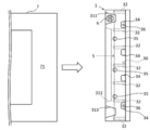
- FIG. 3 schematically illustrates the inner surface 30 of the vehicle interior side wall 3 of the garnish 1 according to the present embodiment.
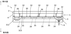
- FIG. 4 schematically illustrates a state in which the garnish 1 according to the present embodiment is viewed from the opening side of the groove 5.
- FIG. 5 schematically illustrates a state in which the garnish 1 according to the present embodiment is viewed from the direction along the groove 5.
- FIG. 6 schematically illustrates a state where the garnish 1 according to the present embodiment is viewed from the vehicle interior side.
- FIG. 7 schematically illustrates a cross section taken along line AA of FIG.
- FIG. 8 schematically illustrates a cross section taken along line BB of FIG.
- the “inside of the vehicle” refers to the direction facing the vehicle inner side (upper side in FIG. 4) when the garnish 1 and the glass plate 7 are mounted on the window of the vehicle, and the “outside of the vehicle” refers to the outer side of the vehicle at that time. (The lower side of FIG. 4).
- the garnish 1 includes a vehicle outer wall portion 2 disposed on the vehicle outer side, a vehicle inner wall portion 3 disposed on the vehicle inner side, and the vehicle outer wall portion 2 and the vehicle inner wall portion 3. It has the groove part 5 comprised by the bottom wall part 4 which connects one end parts of.
- the edge of the glass plate 7 having the shielding layer 71 at the periphery can be inserted into the groove 5 of the garnish 1.
- the garnish 1 is configured so that it can be attached to the glass plate 7 with the end side of the glass plate 7 sandwiched by the vehicle outer side wall portion 2 and the vehicle inner side wall portion 3 of the groove portion 5.
- the “edge” of the glass plate 7 refers to the end portion of the glass plate 7 that is inserted into the groove portion 5 of the garnish 1.
- the garnish 1 includes the vehicle outer wall portion 2, the vehicle inner wall portion 3, and the bottom wall portion 4, and the vehicle outer wall portion 2, the vehicle inner wall portion 3, and the bottom wall portion 4 are inserted.
- the substantially rectangular groove part 5 which clamps the edge side of the glass plate 7 is comprised. This garnish 1 is used to protect the edge of the glass plate 7 mounted on the vehicle window.
- the vehicle exterior wall 2 extends along the edge of the glass plate 7 and has a substantially rectangular cross section.
- the vehicle exterior wall 2 constitutes the vehicle exterior side wall of the groove 5 into which the edge of the glass plate 7 is inserted.
- the inserted glass plate 7 is supported from the outside of the vehicle.
- the vehicle interior side wall 3 is arranged so as to face the vehicle exterior wall 2 in the direction perpendicular to the surface of the glass plate 7 to be inserted. Similar to the vehicle outer wall 2, the vehicle inner wall 3 extends along the edge of the glass plate 7 and has a substantially rectangular cross section.
- the vehicle interior side wall portion 3 constitutes the vehicle interior side wall of the groove portion 5 into which the end of the glass plate 7 is inserted. When the glass plate 7 is inserted into the groove portion 5, the inserted glass plate 7 is inserted. Is supported from the inside.
- the length of the direction (up-down direction of FIG.2 and FIG.6 and the left-right direction of FIG.4) in alignment with the groove part 5 of the vehicle outer side wall part 2 and the vehicle interior side wall part 3 corresponds.
- the length in the direction along the groove portion 5 of the vehicle outer side wall portion 2 and the vehicle inner side wall portion 3 may not be limited to such an example, and may be different from each other.
- the vehicle interior side wall portion 3 includes a front end side region 31 disposed on the front side of the glass plate 7 in the insertion direction, and seven end portions disposed on the rear side in the insertion direction of the glass plate 7 from the front end side region 31. Rib 32.
- the “insertion direction” is a direction in which the glass plate 7 is inserted into the groove portion 5 (left-right direction in FIGS. 2 and 6).
- the “front side in the insertion direction” is the opening side of the groove portion 5 (right side in FIG. 5), whereas the “back side in the insertion direction” is the rear end side of the groove portion 5 (left side in FIG. 5). That is, it is the bottom wall 4 side.
- the seven ribs 32 are provided adjacent to (or connected to) the inner surface of the bottom wall portion 4 and aligned in the direction along the groove portion 5. Yes. As shown in FIGS. 5, 7, and 8, each rib 32 protrudes from the inner surface 30 of the vehicle interior side wall portion 3, and in the region where each rib 32 is provided, compared to the other regions. The distance between the inner surface 30 of the portion 3 and the inner surface (surface on the groove portion 5 side) of the vehicle outer side wall portion 2 is reduced. Thereby, the groove part 5 clamps the edge side of the glass plate 7 with the area
- the seven ribs 32 constitute a support region that supports the vehicle outer side wall portion 2 and the end sides of the glass plate 7.
- Each rib 32 has a cross-sectional shape in which a region on the front side of the rectangular insertion direction is cut out. Thereby, each rib 32 inclines so that thickness may become small toward the insertion direction near side, and it is easy to accept the edge of the glass plate 7 inserted from the opening side of the groove part 5.
- the shape of each rib 32 may not be limited to such an example, and may be appropriately selected according to the embodiment. Note that the height of each rib 32 (the length in the vertical direction in FIGS. 5, 7, and 8) can sandwich the edge of the glass plate 7 between each rib 32 and the inner surface of the vehicle exterior wall portion 2. Thus, it determines suitably based on the distance between the vehicle outer side wall part 2 and the vehicle inner side wall part 3, the thickness of the glass plate 7, etc.
- the tip end region 31 is lower than the upper surface of each rib 32, and is configured to be separated from the glass plate 7 sandwiched between the grooves 5 in the direction perpendicular to the surface.
- the front end side region 31 extends from the end 22 of the vehicle outer side wall portion 2 toward the front side in the insertion direction of the glass plate 7, and near both ends in the direction along the groove portion 5.
- a pair of recesses (311 and 312) and a low step portion 313 recessed at a position lower than the inner surface 30 are provided between the recesses (311 and 312).
- Each recess (311 and 312) is recessed in a trapezoidal shape in the direction perpendicular to the surface, and is a portion that comes into contact with the vehicle body when the glass plate 7 is fixed to the vehicle body, as will be described later.
- a clip 6 for attaching the garnish 1 to the vehicle body is attached to the recess 311. Therefore, on the inner surface 30 side, the recess 311 is recessed from the inner surface 30 to a lower position so that the head of the clip 6 does not protrude from the inner surface 30.
- the low step part 313 is provided in order to separate the front end side region 31 from the glass plate 7 in the direction perpendicular to the inner surface 30.
- the tip side region 31 is only a distance D2 from the glass plate 7 (specifically, the shielding layer 71) sandwiched by the groove portion 5.
- the front end side region 31 is separated from the glass plate 7 by a distance D1 larger than the distance D2.
- Each distance (D1, D2) indicates that when the primer applied to the shielding layer 71 of the glass plate 7 flows toward the groove portion 5, the primer that has flowed in is fixed to both the shielding layer 71 and the tip end region 31.
- the distance D1 may be set in the range of 0.2 mm to 1.4 mm.
- the distance D2 may be set in the range of 0.1 mm to 1.3 mm.
- the corner 33 of the distal end side region 31, that is, the corner 33 on the front side in the insertion direction of the vehicle interior side wall portion 3 has a rounded shape. ing.
- the distance between the vehicle interior side wall portion 3 and the glass plate 7 sandwiched between the groove portions 5 is closer to the front side than the rear side in the insertion direction of the glass plate 7. It is getting bigger.
- the bottom wall part 4 which connects the edge parts of the vehicle outer side wall part 2 and the vehicle interior side wall part 3 is arrange
- the portion of the bottom wall portion 4 between the vehicle outer wall portion 2 and the vehicle inner wall portion 3 constitutes the bottom of the groove portion 5 into which the end side of the glass plate 7 is inserted, and the end surface of the inserted glass plate 7.
- the outer surface 21 of the vehicle outer side wall portion 2 and the outer surface 41 of the bottom wall portion 4 constitute a design surface that can be seen from the vehicle outer side. The shape and pattern of this design surface may be appropriately designed according to the embodiment so as to improve the appearance.
- the glass plate 7 When the glass plate 7 is inserted into the groove portion 5, it becomes difficult to visually recognize the situation inside the groove portion 5 from the opening side (front side in the insertion direction) of the groove portion 5, and the glass plate 7 is inserted to any part of the groove portion 5. It becomes difficult to confirm whether or not. Therefore, in the present embodiment, four through holes 34 penetrating in the thickness direction are provided on the back side in the insertion direction of the vehicle interior side wall portion 3. Three through holes 35 are also provided on the front side in the insertion direction from each through hole 34.
- the four through holes 34 are formed in an approximately elliptical cross section and are aligned in the direction along the groove 5.
- Each through hole 34 is disposed so as to contact the inner surface of the bottom wall portion 4 (the surface facing the inner side of the groove portion 5). Therefore, as shown in FIG. 5, FIG. 6, and FIG. 8, the situation inside the groove portion 5 from the inner surface of the bottom wall portion 4 to the front side in the insertion direction through each through hole 34, It can be visually recognized from the outside (the lower side in FIGS. 5 and 8).
- the three through holes 35 are formed in a substantially circular cross section and are aligned in the direction along the groove 5.
- Each through hole 35 is located on the front side in the insertion direction with respect to each through hole 34. Therefore, as shown in FIG. 5 and FIG. 6, the situation inside the groove portion 5 on the near side in the insertion direction with respect to the region visible through each through-hole 34 via each through-hole 35 is changed as shown in FIG. It can be visually recognized from the outside (the lower side in FIG. 5).
- each protrusion 36 is formed in a substantially rectangular shape in cross section, and the surface on the front side in the insertion direction is curved.
- the end surface of the glass plate 7 is in contact with the curved surface of each protruding portion 36.
- two protrusions 36 on both ends in the direction along the groove 5 are formed from the outside of the vehicle interior side wall 3 through the through holes 34. It is arranged so as to be visible. Thereby, when inserting the edge side of the glass plate 7 in the groove part 5, it is confirmed whether the edge of the glass plate 7 has reached the vicinity of each protrusion part 36 in the both ends of the direction along the groove part 5. Can do.
- the materials for the garnish 1 as described above may be appropriately selected according to the embodiment.
- the garnish 1 can be produced by injection molding using a resin material such as AES (acrylonitrile / ethylene-propylene-diene / styrene) or ASA (Acrylonitrile-Styrene-Acrylate).
- AES acrylonitrile / ethylene-propylene-diene / styrene
- ASA Acrylonitrile-Styrene-Acrylate
- the glass plate 7 to which the garnish 1 is attached will be described.
- the kind of glass plate 7 is a glass plate for motor vehicles, it may not be specifically limited and may be suitably selected according to embodiment.
- the glass plate 7 may be a known automotive glass plate such as heat ray absorbing glass, clear glass, green glass, or UV green glass.
- the size and shape of the glass plate 7 may be appropriately selected according to the embodiment such as the shape of the window to which the glass plate 7 is attached.
- the thickness of the glass plate 7 may be set in the range of 2.4 to 5.0 mm, preferably in the range of 2.5 to 4.0 mm. More preferably, it is set in the range of 7 to 3.2 mm.
- a ceramic shielding layer 71 is laminated on the peripheral portion of the inner surface of the glass plate 7.
- the ceramic constituting the shielding layer 71 for example, dark ceramics such as black, brown, gray, and dark blue are used.
- the shielding layer 71 shields the visual field from the outside of the vehicle at the peripheral edge of the glass plate 7, that is, prevents the portion where the glass plate 7 and the vehicle body are bonded from being visible from the outside of the vehicle, thereby improving the appearance of the automobile. .
- FIGS. 9A to 9F and FIG. 10 the garnish 1 is attached to a glass plate 7, the glass plate 7 is fixed to a vehicle body 85 of an automobile,
- the process of constructing simply “fixed glass window 10” will be described.
- 9A to 9E schematically illustrate the process.
- FIG. 9F schematically illustrates the fixed glass window 10 completed through this process.
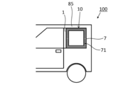
- FIG. 10 schematically illustrates an automobile (vehicle) 100 including a fixed glass window 10 (a so-called fitting window).
- the process demonstrated below is only an example of the method of attaching the garnish 1 and the glass plate 7, and a process omission, substitution, and addition are possible suitably according to embodiment.
- the double-sided tape 81 with the other release paper 82 left is stuck to the inner surface 30 of the vehicle interior side wall 3.
- the double-sided tape 81 is used for bonding the glass plate 7 and the garnish 1 (the vehicle interior side wall portion 3). Therefore, if it can be used in this way, the place where the double-sided tape 81 is attached may be appropriately determined.
- the double-sided tape 81 is attached to the inner surface of the front end side region 31 of the vehicle interior side wall 3.
- the front end side region 31 of the vehicle inner wall portion 3 extends further to the front side in the insertion direction than the end portion 22 of the vehicle outer side wall portion 2. Therefore, as shown in FIG. 9A, the double-sided tape 81 can be attached to the front end side region 31 without being interfered with the vehicle outer side wall portion 2. Therefore, in this embodiment, the operation
- the tip side region 31 is provided with a low step portion 313 that is recessed at a position lower than the inner surface 30. Therefore, the dimension of the double-sided tape 81 may be set so that the double-sided tape 81 is accommodated in the low step portion 313 in the direction along the groove portion 5.
- the double-sided tape 81 is stretched over both sides of the low step portion 313 in the direction along the groove portion 5. You may arrange as follows.
- the distal end side region 31 is configured to be separated from the glass plate 7 sandwiched by the groove portion 5 by a distance D1 or a distance D2 in a direction perpendicular to the surface (thickness direction). Therefore, in this process, it has a thickness T that is thicker than the distance D1 and the distance D2 in the direction perpendicular to the surface between the glass plate 7 sandwiched by the groove portion 5 and the distal end side region 31, and has elasticity in the thickness direction.
- a double-sided tape 81 is used.
- the thickness T of the double-sided tape 81 may be set in the range of 0.4 mm to 1.6 mm.
- the thickness T of the double-sided tape 81 may not be limited to such an example, and may be set as appropriate according to the embodiment.
- the thickness T of the double-sided tape 81 may be approximately the same as the distance D2 between the low step portion 313 and the glass plate 7.
- the edge of the glass plate 7 is inserted into the groove 5 as shown in FIG. 9B.
- each protrusion part 36 is disposed so as to be visible from the outside of the vehicle interior side wall portion 3 through the through holes 34. Therefore, it can be visually confirmed whether or not the glass plate 7 is inserted into the groove portion 5 until the end side of the glass plate 7 comes into contact with each protruding portion 36. Therefore, according to this embodiment, the garnish 1 can be easily and appropriately attached by the glass plate 7.
- the end of the release paper 82 is pulled from between the glass plate 7 and the vehicle interior side wall 3, and the release paper 82 is peeled from the double-sided tape 81.
- the corner on the inner surface 30 side in front of the insertion direction of the inner wall portion 3 is sharp, the release paper 82 is cut by rubbing the corner while the release paper 82 is being peeled off. There is a possibility. If it does so, this process will take time.
- the corner 33 on the inner surface 30 side in front of the insertion direction of the vehicle interior side wall 3 has a rounded shape, so that the release paper 82 is rubbed and cut at the corner 33.
- the release paper 82 can be smoothly peeled off from the double-sided tape 81. Therefore, in this embodiment, this process can be performed quickly.
- the double-sided tape 81 has a thickness T that is thicker than the distance D1 and the distance D2 in the direction perpendicular to the plane between the glass plate 7 and the tip end region 31. Therefore, when the release paper 82 is peeled off, the adhesive surface of the double-sided tape 81 is pressed against the shielding layer 71 of the glass plate 7 by the elasticity of the double-sided tape 81 and can adhere to the shielding layer 71. Therefore, in this embodiment, the glass plate 7 and the garnish 1 can be reliably bonded by the double-sided tape 81.
- a primer 83 is applied to a region on the shielding layer 71 of the glass plate 7 on the inner side in the surface direction from the vehicle interior side wall portion 3, and the applied primer 83 is applied for a predetermined time. dry.
- the garnish 1 will be in the state which clamps the edge side of the glass plate 7 in the surface direction outer side rather than the area
- the shielding layer 71 is made of ceramic, the adhesive is difficult to fix as it is. Therefore, the adhesive 84 is easily fixed to the shielding layer 71 by applying the primer 83 to a region where the adhesive 84 described later is applied.
- the primer 83 may flow into the groove portion 5 from the applied region while the primer 83 is dried.
- each distance (in the perpendicular direction) between the glass plate 7 (the shielding layer 71) and the tip side region 31 ( D1, D2) are set appropriately.
- the primer 83 Hamatite G (MS-90) manufactured by Yokohama Rubber Co., Ltd. can be used.
- the primer 83 is a Ford Cup No. It has a viscosity of 13 sec / 20 ° C. with a four viscometer (JISK5400), and when applied to the shielding layer 71, its thickness becomes about 4 to 20 ⁇ m. Therefore, at this time, even if the primer 83 applied to the shielding layer 71 flows toward the groove portion 5, as described above, the glass plate 7 is prevented from being fixed to both the shielding layer 71 and the vehicle interior wall portion 3.
- the distances (D1, D2) in the direction perpendicular to the (shielding layer 71) and the tip side region 31 are set in the range of 0.2 mm to 1.4 mm and 0.1 mm to 1.3 mm.
- the type of the primer 83 may be appropriately selected according to the embodiment.
- 435-40 manufactured by Sunstar Giken can be used as the primer 83.
- the adhesive 84 is applied to the region where the primer 83 is applied, the clip 6 and the hole 86 of the vehicle body 85 are aligned, and then the glass plate 7 is mounted on the vehicle body. Press against 85. 9F, the glass plate 7 is fixed to the vehicle body 85 by the primer 83 and the adhesive 84 applied to the shielding layer 71, and the fixed glass window 10 shown in FIG. 9F can be manufactured. That is, as shown in FIG. 10, the glass plate 7 can be attached to the window of the automobile 100 (vehicle), and the automobile 100 having the fixed glass window 10 can be manufactured.
- the adhesive 84 for example, a urethane-based adhesive or the like can be used.
- the fixed glass window 10 is, for example, a window such as a side rear window or a front bench (triangular window).
- the front end side region 31 of the vehicle interior side wall portion 3 constituting the groove portion 5 into which the end side of the glass plate 7 is inserted is formed from the glass plate 7 as shown in FIG. 9D. They are separated by a distance (D1, D2) in the direction perpendicular to the surface. Therefore, in the fourth step, the primer 83 is applied to the shielding layer 71 provided on the periphery of the inner surface of the glass plate 7, and the applied primer 83 flows into the groove portion 5 of the garnish 1. In addition, the primer 83 that has flowed in can be prevented from being fixed on both the shielding layer 71 and the surface of the tip side region 31.
- the present embodiment it is possible to reduce the possibility that the shielding layer 71 and the vehicle interior side wall portion 3 are firmly bonded by the primer 83, and thereby, the peeling of the shielding layer 71, the damage of the garnish 1, etc. It is possible to make it difficult for a failure to occur.
- the distance between the vehicle interior side wall part 3 and the glass plate 7 is larger on the near side than the far side in the insertion direction. That is, the closer to the region where the primer 83 is applied, the wider the distance between the vehicle interior side wall 3 and the glass plate 7. Therefore, when the applied primer 83 flows toward the garnish 1 in the fourth step, the flow of the primer 83 is further suppressed from being fixed to both the surface of the shielding layer 71 and the tip side region 31. can do. Therefore, according to the present embodiment, the possibility that the shielding layer 71 and the vehicle interior side wall portion 3 are firmly bonded by the primer 83 can be extremely reduced, and as a result, the shielding layer 71 is peeled off, the garnish 1 is damaged, and the like. It is possible to further prevent the occurrence of the trouble.
- the support region that supports the outer side wall portion 2 and the edge of the glass plate 7 is constituted by seven ribs 32 protruding from the inner surface 30 of the inner wall portion 3. Therefore, a gap can be provided between the glass plate 7 and the vehicle interior side wall 3 in a region where each rib 72 is not provided, such as a region between adjacent ribs 32. That is, the area in contact with the glass plate 7 and the vehicle interior side wall 3 can be made extremely small. Therefore, according to the present embodiment, the possibility that the shielding layer 71 of the glass plate 7 and the in-car side wall portion 3 are bonded by the primer 83 can be extremely reduced, whereby the shielding layer 71 is peeled off and the garnish 1 is removed. Failures such as breakage can be further prevented from occurring.
- the vehicle interior side wall 3 of the garnish 1 is provided with two types of through holes (34, 35).
- each through hole (34, 35) may be omitted.
- four through holes 34 are provided, and three through holes 35 are provided.
- the number of each through-hole (34, 35) may not be limited to such an example, and may be appropriately selected according to the embodiment.
- Each through-hole (34, 35) may be singular or plural.
- three protrusions 36 are provided on the inner surface of the bottom wall 4 on the groove 5 side.
- the number of the protrusions 36 may not be limited to such an example, and may be appropriately selected according to the embodiment.
- the protrusion 36 may be singular or plural. This protrusion 36 may be omitted.
- two of the three protrusion parts 36 are arrange
- the projecting portions 36 may be arranged so as to be visible from the outside of the vehicle interior side wall portion 3 through the through holes 34.
- the arrangement of the protrusions 36 is not limited to such an example, and all the protrusions 36 may be arranged so that they cannot be seen from the outside of the vehicle interior side wall 3.
- region of the vehicle interior side wall part 3 which supports the vehicle outer side wall part 2 and the edge side of the glass plate 7 is comprised by the seven ribs 32.
- the rib 32 may be single or plural.
- the support region is not configured by one or a plurality of ribs, but may be configured in other forms.
- the support region may be configured by a region that protrudes in the direction perpendicular to the inner surface 30 of the vehicle interior side wall portion 3 and is formed over the entire region along the groove portion 5.
- each rib 32 is provided adjacent to the inner surface of the bottom wall portion 4.
- the rib 32 may not be limited to such an example, and each rib 32 may be provided away from the inner surface of the bottom wall portion 4 toward the opening side.
- the garnish 1 and the vehicle body 85 are connected by the clip 6. This clip 6 may be omitted. Further, the garnish 1 and the vehicle body 85 may be connected by a method other than the clip 6. A method for connecting the garnish 1 and the vehicle body 85 may be appropriately selected according to the embodiment.
- the distal end side region 31 includes a pair of concave portions (311 and 312) and a low step portion 313.
- the shape of the distal end side region 31 may not be limited to such an example, and may be appropriately designed according to the embodiment. For example, modifications as shown in FIGS. 11 to 13 are possible.
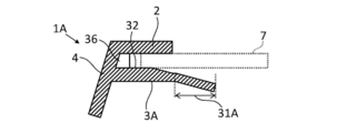
- FIG. 11 exemplifies the garnish 1A formed so as to be inclined away from the glass plate 7 in other words, the tip side region 31A of the vehicle interior side wall 3A.
- the tip end region may have a shape in which the distance from the glass plate 7 sandwiched between the grooves 5 gradually increases from the back side to the front side in the insertion direction.
- the position to attach the double-sided tape is set, and the set position What is necessary is just to determine the thickness of a double-sided tape on the basis of the distance between the glass plate and the front end side region.
- FIG. 12 illustrates a garnish 1B having a shape in which a corner 33B on the inner surface 30 side of the front end side region 31B of the vehicle interior side wall 3B is cut out.
- the corner on the inner surface side of the distal end side region may not have a rounded shape.
- the front end side region may have a shape in which only the end portion on the near side in the insertion direction is further away from the glass plate 7.
- FIG. 13 illustrates a garnish 1C in which the front end side region 31C of the vehicle interior side wall 3C is flat.
- the front end side region of the vehicle interior side wall portion is closer to the front side than the back side in the insertion direction, and is a glass plate sandwiched between the groove portions 7 was configured to increase the distance.
- the shape of the front end side region does not have to be limited to such an example, and the front end side region of the vehicle interior side wall portion is a glass plate 7 sandwiched by the groove portion 5 from the back side to the front side in the insertion direction. May be configured to be constant.
- the vehicle interior side wall 3 is longer than the vehicle exterior wall 2 in the insertion direction (left and right directions in FIGS. 2 and 5 to 8).
- the dimensional relationship between the vehicle outer wall portion 2 and the vehicle inner wall portion 3 may not be limited to such an example.
- the vehicle outer wall 2 and the vehicle inner wall 3 may have the same length in the insertion direction.
- the double-sided tape 81 was arrange
- the arrangement of the double-sided tape 81 may not be limited to such an example, and may be appropriately selected according to the embodiment. Further, the double-sided tape 81 may be omitted.
Landscapes
- Engineering & Computer Science (AREA)
- Mechanical Engineering (AREA)
- Vehicle Interior And Exterior Ornaments, Soundproofing, And Insulation (AREA)
Abstract
L'invention concerne une garniture pour des véhicules dans laquelle une couche de protection n'est pas susceptible de se séparer et la garniture n'est pas sujette à une défaillance telle qu'une rupture. Une garniture pour des véhicules selon un aspect de la présente invention saisit un bord d'une plaque de verre montée sur une fenêtre d'un véhicule. La garniture est pourvue d'une section de paroi côté extérieur du véhicule disposée sur l'extérieur du véhicule ; d'une section de paroi côté intérieur du véhicule disposée en face de la section de paroi côté extérieur du véhicule ; d'une section de paroi inférieure qui est disposée sur le côté éloigné dans la direction d'insertion de la plaque de verre, qui relie une extrémité de la section de paroi côté extérieur du véhicule et une extrémité de la section de paroi côté intérieur du véhicule, et qui constitue une rainure pour saisir le bord de la plaque de verre insérée en coopération avec la section de paroi côté extérieur du véhicule et la section de paroi côté intérieur du véhicule. La section de paroi côté intérieur du véhicule présente : une région d'extrémité avant disposée sur le côté proche dans la direction d'insertion de la plaque de verre et configurée pour être située à une certaine distance de la plaque de verre saisie dans la direction perpendiculaire à la surface de celle-ci ; une région de support disposée davantage vers le côté éloigné dans la direction d'insertion de la plaque de verre que la région d'extrémité avant et soutenant le bord de la plaque de verre en coopération avec la section de paroi côté extérieur du véhicule.
Applications Claiming Priority (2)
| Application Number | Priority Date | Filing Date | Title |
|---|---|---|---|
| JP2016090277A JP6640012B2 (ja) | 2016-04-28 | 2016-04-28 | 車両用ガーニッシュ |
| JP2016-090277 | 2016-04-28 |
Publications (1)
| Publication Number | Publication Date |
|---|---|
| WO2017187825A1 true WO2017187825A1 (fr) | 2017-11-02 |
Family
ID=60160354
Family Applications (1)
| Application Number | Title | Priority Date | Filing Date |
|---|---|---|---|
| PCT/JP2017/010358 Ceased WO2017187825A1 (fr) | 2016-04-28 | 2017-03-15 | Garniture pour véhicules |
Country Status (2)
| Country | Link |
|---|---|
| JP (1) | JP6640012B2 (fr) |
| WO (1) | WO2017187825A1 (fr) |
Citations (5)
| Publication number | Priority date | Publication date | Assignee | Title |
|---|---|---|---|---|
| JPS4732523A (fr) * | 1971-01-01 | 1972-11-15 | ||
| JPS5322423U (fr) * | 1976-08-05 | 1978-02-24 | ||
| JPS61169716U (fr) * | 1985-04-10 | 1986-10-21 | ||
| JPH01175413U (fr) * | 1988-06-01 | 1989-12-13 | ||
| JPH02222U (fr) * | 1988-06-15 | 1990-01-05 |
-
2016
- 2016-04-28 JP JP2016090277A patent/JP6640012B2/ja active Active
-
2017
- 2017-03-15 WO PCT/JP2017/010358 patent/WO2017187825A1/fr not_active Ceased
Patent Citations (5)
| Publication number | Priority date | Publication date | Assignee | Title |
|---|---|---|---|---|
| JPS4732523A (fr) * | 1971-01-01 | 1972-11-15 | ||
| JPS5322423U (fr) * | 1976-08-05 | 1978-02-24 | ||
| JPS61169716U (fr) * | 1985-04-10 | 1986-10-21 | ||
| JPH01175413U (fr) * | 1988-06-01 | 1989-12-13 | ||
| JPH02222U (fr) * | 1988-06-15 | 1990-01-05 |
Also Published As
| Publication number | Publication date |
|---|---|
| JP2017197045A (ja) | 2017-11-02 |
| JP6640012B2 (ja) | 2020-02-05 |
Similar Documents
| Publication | Publication Date | Title |
|---|---|---|
| WO2018123777A1 (fr) | Verre de fenêtre avec élément d'étanchéité monté sur celui-ci | |
| US20180304822A1 (en) | Trim part with integrated antenna | |
| JP7378296B2 (ja) | カウルルーバとモール付きウインドシールドとの連接構造 | |
| CN105599571B (zh) | 车辆树脂面板结构 | |
| WO2017187825A1 (fr) | Garniture pour véhicules | |
| US11312210B2 (en) | Vehicle body upper structure | |
| JP5474912B2 (ja) | 車両用窓板の装飾部材 | |
| JP5216756B2 (ja) | 車両用モールディングの連結構造 | |
| US10106117B2 (en) | Roof headliner with silicone energy absorption panel | |
| JP4428506B2 (ja) | 自動車用ウインドモール | |
| JP2010280246A (ja) | 車両用ホイールアーチガーニッシュの取付構造 | |
| KR20220072665A (ko) | 미러를 차량의 내부에 부착하기 위한 구조 및 이를 포함하는 내부미러 | |
| JP2010235092A (ja) | 自動車のドア | |
| JP2015157528A (ja) | ウィンドシールドロアモール | |
| JP3803117B2 (ja) | 車両用カウルルーバ | |
| JP2007314067A (ja) | ピラーガーニッシュの上部合わせ構造 | |
| CN211942929U (zh) | 一种高密封性的汽车前挡饰板 | |
| CN206217791U (zh) | 立柱饰板、立柱总成和车辆 | |
| JP5320365B2 (ja) | ランプユニット位置決め構造 | |
| CN213384120U (zh) | A柱外装饰板及汽车 | |
| CN118991939A (zh) | 车辆 | |
| KR20040052069A (ko) | 자동차용 투명 a필러구조 | |
| CN209904500U (zh) | 一种汽车车门导轨端盖、车门以及汽车 | |
| KR102259785B1 (ko) | 차량용 테일게이트 구조 | |
| KR102220692B1 (ko) | 자동차용 a-필러 가니쉬 |
Legal Events
| Date | Code | Title | Description |
|---|---|---|---|
| NENP | Non-entry into the national phase |
Ref country code: DE |
|
| 121 | Ep: the epo has been informed by wipo that ep was designated in this application |
Ref document number: 17789114 Country of ref document: EP Kind code of ref document: A1 |
|
| 122 | Ep: pct application non-entry in european phase |
Ref document number: 17789114 Country of ref document: EP Kind code of ref document: A1 |