WO2017187919A1 - Dispositif de retraitement d'endoscope - Google Patents
Dispositif de retraitement d'endoscope Download PDFInfo
- Publication number
- WO2017187919A1 WO2017187919A1 PCT/JP2017/014312 JP2017014312W WO2017187919A1 WO 2017187919 A1 WO2017187919 A1 WO 2017187919A1 JP 2017014312 W JP2017014312 W JP 2017014312W WO 2017187919 A1 WO2017187919 A1 WO 2017187919A1
- Authority
- WO
- WIPO (PCT)
- Prior art keywords
- endoscope
- processing tool
- gravity
- fluid
- discharge
- Prior art date
- Legal status (The legal status is an assumption and is not a legal conclusion. Google has not performed a legal analysis and makes no representation as to the accuracy of the status listed.)
- Ceased
Links
Images


Classifications
-
- A—HUMAN NECESSITIES
- A61—MEDICAL OR VETERINARY SCIENCE; HYGIENE
- A61B—DIAGNOSIS; SURGERY; IDENTIFICATION
- A61B1/00—Instruments for performing medical examinations of the interior of cavities or tubes of the body by visual or photographical inspection, e.g. endoscopes; Illuminating arrangements therefor
- A61B1/12—Instruments for performing medical examinations of the interior of cavities or tubes of the body by visual or photographical inspection, e.g. endoscopes; Illuminating arrangements therefor with cooling or rinsing arrangements
- A61B1/121—Instruments for performing medical examinations of the interior of cavities or tubes of the body by visual or photographical inspection, e.g. endoscopes; Illuminating arrangements therefor with cooling or rinsing arrangements provided with means for cleaning post-use
- A61B1/123—Instruments for performing medical examinations of the interior of cavities or tubes of the body by visual or photographical inspection, e.g. endoscopes; Illuminating arrangements therefor with cooling or rinsing arrangements provided with means for cleaning post-use using washing machines
-
- A—HUMAN NECESSITIES
- A61—MEDICAL OR VETERINARY SCIENCE; HYGIENE
- A61B—DIAGNOSIS; SURGERY; IDENTIFICATION
- A61B1/00—Instruments for performing medical examinations of the interior of cavities or tubes of the body by visual or photographical inspection, e.g. endoscopes; Illuminating arrangements therefor
- A61B1/00064—Constructional details of the endoscope body
- A61B1/00071—Insertion part of the endoscope body
- A61B1/0008—Insertion part of the endoscope body characterised by distal tip features
- A61B1/00098—Deflecting means for inserted tools
-
- A—HUMAN NECESSITIES
- A61—MEDICAL OR VETERINARY SCIENCE; HYGIENE
- A61B—DIAGNOSIS; SURGERY; IDENTIFICATION
- A61B90/00—Instruments, implements or accessories specially adapted for surgery or diagnosis and not covered by any of the groups A61B1/00 - A61B50/00, e.g. for luxation treatment or for protecting wound edges
- A61B90/70—Cleaning devices specially adapted for surgical instruments
-
- A—HUMAN NECESSITIES
- A61—MEDICAL OR VETERINARY SCIENCE; HYGIENE
- A61L—METHODS OR APPARATUS FOR STERILISING MATERIALS OR OBJECTS IN GENERAL; DISINFECTION, STERILISATION OR DEODORISATION OF AIR; CHEMICAL ASPECTS OF BANDAGES, DRESSINGS, ABSORBENT PADS OR SURGICAL ARTICLES; MATERIALS FOR BANDAGES, DRESSINGS, ABSORBENT PADS OR SURGICAL ARTICLES
- A61L2/00—Disinfection or sterilisation of materials or objects, in general; Accessories therefor
- A61L2/26—Accessories
-
- A—HUMAN NECESSITIES
- A61—MEDICAL OR VETERINARY SCIENCE; HYGIENE
- A61B—DIAGNOSIS; SURGERY; IDENTIFICATION
- A61B90/00—Instruments, implements or accessories specially adapted for surgery or diagnosis and not covered by any of the groups A61B1/00 - A61B50/00, e.g. for luxation treatment or for protecting wound edges
- A61B90/70—Cleaning devices specially adapted for surgical instruments
- A61B2090/701—Cleaning devices specially adapted for surgical instruments for flexible tubular instruments, e.g. endoscopes
-
- A—HUMAN NECESSITIES
- A61—MEDICAL OR VETERINARY SCIENCE; HYGIENE
- A61L—METHODS OR APPARATUS FOR STERILISING MATERIALS OR OBJECTS IN GENERAL; DISINFECTION, STERILISATION OR DEODORISATION OF AIR; CHEMICAL ASPECTS OF BANDAGES, DRESSINGS, ABSORBENT PADS OR SURGICAL ARTICLES; MATERIALS FOR BANDAGES, DRESSINGS, ABSORBENT PADS OR SURGICAL ARTICLES
- A61L2103/00—Materials or objects being the target of disinfection or sterilisation
- A61L2103/15—Laboratory, medical or dentistry appliances, e.g. catheters or sharps
Definitions
- the present invention relates to an endoscope reproduction processing tool used for endoscope reproduction processing.
- Some endoscopes used in the medical field can project a treatment tool such as a forceps or a puncture needle from a treatment tool insertion opening opened at the distal end of the insertion portion.
- a treatment tool such as a forceps or a puncture needle
- Japanese Patent Application Laid-Open No. 2006-246933 discloses an endoscope including a forceps raising base that guides the protruding direction of a treatment tool protruding from a treatment tool insertion port and swings the treatment tool.
- the treatment instrument elevator can be stored in a recess provided at the distal end so as not to hinder the movement of the endoscope within the subject.
- endoscopes used in the medical field are subjected to regeneration processing such as cleaning and disinfection after use.
- the endoscope reproduction process can be automatically performed by an endoscope reprocessor.
- the regeneration process is performed on the recess portion where dirt easily adheres. It is preferable to focus on.
- an endoscope reprocessor is used to perform a reproduction process on an endoscope having a concave portion at the distal end portion of the insertion portion, a manual operation performed by a person before the reproduction processing such as brushing in the concave portion is performed. Mitigation or omission is required.
- An object of the present invention is to provide an endoscope regeneration processing tool capable of performing regeneration processing.
- An endoscope regeneration processing tool includes a connection portion connected to a fluid outlet provided on a bottom surface of a processing tank of an endoscope reprocessor, and a flow of fluid discharged from the fluid outlet.
- a direction changing unit that changes the direction from a direction opposite to the direction of gravity to a direction that intersects the direction of gravity
- a discharge unit that discharges the fluid changed in direction by the direction changing unit in a direction that intersects the direction of gravity
- the discharge And a positioning portion that positions the distal end portion so that the concave portion provided at the distal end portion of the endoscope faces the concave portion.
- an endoscope reproduction processing tool is provided on the bottom surface of the processing tank of the endoscope reprocessor and connected to a nozzle that discharges fluid in a direction intersecting the direction of gravity. And a positioning portion for positioning the endoscope distal end so that the nozzle and the concave portion provided in the endoscope distal end face each other.
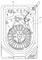
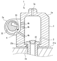
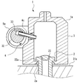
- FIG. 3 is a sectional view taken along line III-III in FIG. 2. It is the figure which looked at the processing tank of the endoscope reprocessor from the upper part. It is a figure which shows the state which has arrange
- FIG. 3 shows the cross section of FIG.
- FIG. 3 it is a figure which shows the state which connected the connection part of the endoscope reproduction
- FIG. 1 it is a figure which shows the state which connected the connection part of the endoscope reproduction
- upper refers to a position that is further away from the ground relative to the comparison target
- lower refers to a position that is closer to the ground relative to the comparison target.
- the height in the following description shall show the height relationship along the gravity direction.
- the endoscope reproduction processing tool 1 of the present embodiment shown in FIGS. 1 to 3 is used together with an endoscope reprocessor 20 that is a device that performs a reproduction process on an endoscope.
- the regeneration treatment here is not particularly limited, and is a rinsing treatment with water, a washing treatment for removing dirt such as organic matter, a disinfection treatment for invalidating predetermined microorganisms, a sterilization treatment for eliminating or killing all microorganisms, Or any combination thereof may be used.
- the endoscope reprocessor 20 includes a processing tank 21 that houses the endoscope 30.
- the endoscope reprocessor 20 has a configuration for introducing a liquid such as a cleaning liquid, a disinfecting liquid, a sterilizing liquid, water, or a drying liquid into the processing tank 21, and an endoscope 30 disposed in the processing tank 21. A reproduction process is performed on the image.
- the processing tank 21 opens upward, and although not shown in FIG. 4, a lid 23 that opens and closes the opening is provided at the opening of the processing tank 21.
- a fluid outlet 22 is disposed on the bottom surface 21 a of the treatment tank 21.
- the fluid outlet 22 discharges the fluid into the treatment tank 21 in a direction against the direction of gravity or in a direction intersecting with the direction of gravity.
- the direction against the gravitational direction is not limited to the direction vertically upward from the ground (horizontal plane), and includes a direction obliquely upward from the ground. That is, the fluid outlet 22 is connected to a pump (not shown) provided in the endoscope reprocessor 20, and discharges fluid from the bottom surface 21 a of the processing tank 21 by operating the pump.
- the fluid discharged from the fluid outlet 22 is a fluid used for the regeneration process, such as a cleaning liquid, a disinfecting liquid, a sterilizing liquid, water, or a drying liquid.
- the cleaning liquid is not particularly limited, and examples thereof include a surfactant. Although it does not specifically limit as disinfection liquid or sterilization liquid, For example, peracetic acid aqueous solution, glutaraldehyde aqueous solution, orthophthalaldehyde aqueous solution, strong acidic electrolysis water, alcohol, or sodium hypochlorite aqueous solution is mentioned. Although it does not specifically limit as a drying liquid, For example, alcohol or acetone is mentioned.
- the fluid outlet 22 is a cleaning case attachment port for attaching / detaching the cleaning case as an example in the present embodiment.
- the cleaning case is a container-like member that accommodates inside the processing tank 21 a part to be subjected to a regeneration process such as an accessory of the endoscope 30.
- the cleaning case When the cleaning case is attached to the fluid outlet 22 which is a cleaning case attachment port, the cleaning case has an opening for guiding the fluid discharged from the fluid outlet 21 to the inside, and the inner fluid is led to the outside. An opening is provided.
- the cleaning case containing the component is mounted on the fluid outlet 22 and the regeneration process for the endoscope 30 is executed, the fluid is introduced into the cleaning case, and the regeneration process is performed on the stored component.
- the cleaning case is not particularly limited, and examples thereof include an endoscope accessory case 61 of Japanese Patent Application No. 2016-066571.
- the fluid outlet 22 of the present embodiment is a nozzle having an outer shape that is provided so as to protrude upward from the bottom surface 21 a of the processing tank 21.
- a flange 22a is formed on the outer peripheral surface of the fluid outlet port 22 to be engaged with a first attaching / detaching portion 2a of the endoscope reproduction processing tool 1 described later.
- the fluid outlet 22 is not limited to the configuration in which the cleaning case is directly attached and detached.
- the fluid outlet 22 may be an accessory cleaning nozzle mounting port to which an accessory cleaning nozzle that discharges fluid toward a side surface of a cleaning case that is disposed away from the fluid may be attached or detached.
- the fluid outlet 22 may be a top surface cleaning nozzle that discharges the fluid toward the inner surface of the lid 23 disposed above the processing tank 21, and the fluid outlet 22 may be the top surface cleaning nozzle. May be a detachable top surface cleaning nozzle mounting opening.
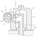
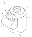
- the endoscope reproduction processing tool 1 includes a connection part 2, a direction changing part 3, a discharge part 4, and a positioning part 5.
- the endoscope regeneration processing tool 1 includes, as an example, a dome-shaped main body 1a that covers the fluid outlet 22 that protrudes from the bottom surface 21a of the processing tank 21. That is, a space is provided inside the main body 1a.
- connection unit 2 is connected to a fluid outlet 22 provided on the bottom surface 21a of the processing tank 21 of the endoscope reprocessor 20.
- the connection part 2 holds the main body part 1a at a position where a later-described direction changing part 3 and the fluid outlet 22 of the endoscope reproduction processing tool 1 communicate with each other in the processing tank 21. Therefore, when the connecting portion 2 is connected to the fluid outlet port 22, the fluid discharged from the fluid outlet port 22 flows into the direction changing portion 3 through the connecting portion 2.
- connection part 2 of this embodiment is a hole provided in the outer surface of the main-body part 1a, and can insert the fluid outlet 22 which protrudes from the bottom face 21a of the process tank 21 inside.
- connection part 2 of this embodiment is equipped with the nail
- the tip of the first attaching / detaching portion 2a protrudes radially inward from the outer diameter of the flange 22a protruding from the outer peripheral surface of the fluid outlet port 22.
- the first attaching / detaching portion 2a allows the passage of the flange 22a by elastic deformation.
- connection portion 2 when the connection portion 2 is pressed against the fluid outlet port 22 from above, as shown in FIG. 6, the flange 22a passes through the first attachment / detachment portion 2a and is positioned above the first attachment / detachment portion 2a. It advances to the connection part 2 until.
- the first attaching / detaching portion 2a engages with the flange 22a to generate a reaction force. Therefore, in the state shown in FIG. 6, the endoscope reproduction processing tool 1 is held at a predetermined position by the connecting portion 2.
- connection unit 2 has a configuration that allows the endoscope reproduction processing tool 1 to be attached to and detached from the fluid outlet port 22.
- the surface that engages with the flange 22a of the first attaching / detaching portion 2a is a flat surface, but this surface may be provided with irregularities such as a plurality of protrusions and grooves.
- the contact frequency between the first attaching / detaching portion 2a and the flange 22a and the fluid used for the regeneration process is increased. be able to.
- the surface on which the connecting portion 2 of the main body 1a is opened is referred to as the lower surface 1b.
- the lower surface 1 b is a surface that faces downward when the connection portion 2 is connected to the fluid outlet port 22.
- the lower surface 1b of the main body 1a is a flat surface, but the lower surface may be provided with irregularities such as a plurality of protrusions and grooves.
- the direction changing unit 3 changes the flow direction of the fluid discharged from the fluid outlet 22 to a direction intersecting with the direction of gravity in a state where the connecting portion 2 is connected to the fluid outlet 22.
- the direction changing part 3 is a space formed in the main body part 1 a as described above, and communicates with the connection part 2.
- the direction changing unit 3 communicates with the discharge unit 4.
- the discharge unit 4 discharges the fluid whose direction has been changed by the direction changing unit 3 in a direction intersecting the direction of gravity in a state where the connection unit 2 is connected to the fluid outlet port 22.
- the discharge direction of the fluid discharged from the fluid outlet 22 is not limited to the direction vertically upward from the ground, and includes a direction obliquely upward from the ground.
- the direction changing unit 3 brings the fluid flow direction closer to the direction in which the angle formed with the gravity direction becomes smaller.
- the direction changing portion 3 of the present embodiment has a wall surface that is disposed above the connecting portion 2 and covers the fluid outlet 22 when the connecting portion 2 is connected to the fluid outlet 22.
- the direction change part 3 of this embodiment to show in figure is a cylinder shape with which one end connected to the connection part 2 and the other end closed. Further, the direction changing portion 3 may be provided with a top surface cleaning hole 3 a for discharging the fluid toward the inner surface of the lid 23 disposed above the processing tank 21.
- the shape of the direction changing portion 3 is not limited to this embodiment, and the direction changing portion 3 may be, for example, a spherical shape, a hemispherical shape, or a box shape, or a slope facing the discharge portion 4. May be.
- the discharge unit 4 of the present embodiment includes a plurality of holes 4b penetrating from the outer surface of the direction changing unit 3 to the internal space.
- the discharge section 4 is provided at a location that is a side surface of the main body section 1 a when the connection section 2 is connected to the fluid outlet port 22.
- the plurality of holes 4b are formed in the discharge part 4 so as to follow a line intersecting at a predetermined angle with respect to the direction of gravity.
- the discharge part 4 discharges the fluid discharged from the fluid outlet 22 in the direction intersecting the gravity direction from the side surface of the direction changing part 3 in a state where the connection part 2 is connected to the fluid outlet 22.
- the plurality of holes 4b have a shape penetrating linearly from the outer surface of the direction changing portion 3 to the internal space, but the plurality of holes 4b are bent in the middle. It may be a nozzle shape protruding from the outer surface.
- the discharge part 4 may be provided with slits instead of a plurality of holes, or may be provided with both holes and slits.
- the plurality of holes 4 b are arranged in a substantially horizontal direction when the connecting portion 2 is connected to the fluid outlet port 22. There may be at least one row of the plurality of holes 4b, and a plurality of rows of the plurality of holes 4b may be provided in the vertical direction. In the illustrated embodiment, as an example, three rows in which a plurality of holes 4b are arranged in the horizontal direction are provided in the vertical direction.
- the individual holes 4b are arranged such that the intersection angle ⁇ between the fluid discharge direction and the gravity direction becomes smaller as the row is farther from the gravity source (the higher row). It is preferable that two or more rows in which the angle is set are included.
- intersection angle ⁇ between the fluid ejection direction and the gravity direction is 90 degrees when the fluid ejection direction is horizontal, and increases when the fluid ejection direction is above horizontal. . That is, the intersection angle ⁇ between the fluid ejection direction and the gravity direction is greater than 90 degrees when the fluid ejection direction is an elevation angle, and smaller than 180 degrees, and 90 when the fluid ejection direction is a depression angle. It is smaller than 0 degree and larger than 0 degree.
- the fluid discharged from the individual rows flows so as to intersect the fluid discharged from the other rows.
- a hole having a smaller crossing angle ⁇ than the lower row or a hole having a larger crossing angle ⁇ than the upper row may be arranged between these rows, above the rows, or below the rows.
- a hole having a crossing angle ⁇ of 90 degrees may be provided further below the hole 4b illustrated at the bottom of FIG.
- the fluid discharged from these holes is discharged toward a portion other than the concave portion 33 provided at the distal end portion 32 of the insertion portion 31 of the endoscope 30, for example, the outer surface of the distal end portion 32.
- the discharge unit 4 and the recess 33 provided in the distal end portion 32 of the insertion unit 31 of the endoscope 30 are opposed to each other.
- the tip portion 32 is positioned at the position.
- tip part 32 of the insertion part 31 of the endoscope 30 is a recessed part by which a treatment tool rocking
- connection portion 2 of the endoscope regeneration processing tool 1 is connected to the fluid outlet port 22, and the insertion portion 31 of the endoscope 30 is positioned by the positioning portion 5.
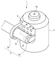
- the positioning part 5 of the present embodiment includes a holding part 5a surrounding the distal end part 32 of the insertion part 31 of the endoscope 30, and an abutting part 5b against which the distal end part 32 inserted into the holding part 5a abuts. Have.
- the holding portion 5 a surrounds the periphery of the distal end portion 32 when the distal end portion 32 of the insertion portion 31 is viewed from the insertion direction.
- the insertion direction of the distal end portion 32 is the longitudinal direction of the insertion portion 31 having an elongated shape.
- the holding part 5a surrounds the periphery of the tip part 32, so that when the connection part 2 is connected to the fluid outlet 22, the positioning of the tip part 32 in the vertical direction with respect to the discharge part 4 and the discharge part of the tip part 32 are performed. Positioning of the separation distance in the horizontal direction from 4 is performed. Further, it is preferable that the distance between the tip portion 32 and the discharge portion 4 is short.
- the holding portion 5a includes a through hole drilled along an axis that is horizontal when the connection portion 2 is connected to the fluid outlet port 22, and the through hole Has an inner diameter larger than the outer diameter of the tip portion 32.
- the distal end portion 32 is inserted into the through hole, thereby positioning the distal end portion 32 in the vertical direction and the separation distance with respect to the discharge portion 4.
- the holding portion 5a includes a circular through hole, but the through hole may have another shape such as a rectangular shape.
- the shape of the holding portion 5a is not limited to the shape surrounding the entire periphery of the tip portion 32 as in the present embodiment, and may be any shape that allows positioning of the tip portion 32 in the vertical direction and the separation distance with respect to the discharge portion 4. Good.
- the holding portion 5 a has a shape including a pair of rod-like members arranged above and below the tip portion 32 and a rod-like member arranged so as to sandwich the tip portion 32 between the discharge portion 4. Also good.
- the holding part 5a may be C-shaped.
- the abutting portion 5b abuts on the end portion of the tip portion 32 when the tip portion 32 is inserted into the through hole of the holding portion 5a by a predetermined length, and positioning the tip portion 32 with respect to the discharge portion 4 in the insertion direction. I do.
- the abutting portion 5b is a protrusion protruding from the outer surface of the direction changing portion 3.
- the shape of the abutting portion 5b is not limited to this embodiment, and the inside of the holding portion 5a. Any shape that restricts the positions of the distal end portion 32 and the discharge portion 4 to be inserted into the discharge portion 4 may be used.
- the abutting portion 5b may be a net-like member disposed at a predetermined distance in the insertion direction from the holding portion 5a.
- the endoscope regeneration processing tool 1 includes the connection portion 2 connected to the fluid outlet 22 provided on the bottom surface 21a of the processing tank 21 of the endoscope reprocessor 20, and the fluid outlet.
- a direction changing unit 3 that changes the direction of flow of the fluid discharged from 22 from a direction against the direction of gravity to a direction that intersects the direction of gravity, and a direction that changes the direction of the fluid changed by the direction changing unit 3 to the direction of gravity.
- a positioning portion 5 that positions the concave portion 33 provided at the distal end portion 32 of the insertion portion 31 of the endoscope 30 so as to face the discharge portion 4.
- the fluid outlet 22 is a part for discharging a fluid used for the regeneration process when the endoscope reprocessor 20 executes the regeneration process. Therefore, when the endoscope reproduction processing tool 1 according to the present embodiment is used, when the reproduction processing by the endoscope reprocessor 20 is performed, the inside of the recess 33 provided in the distal end portion 32 of the insertion portion 31 of the endoscope 30. In addition, the fluid used for the regeneration process can be fed into the recess 33 so that the regeneration process can be focused.
- the discharge unit 4 of the endoscope reproduction processing tool 1 of the present embodiment includes a row in which a plurality of holes 4b for discharging a fluid are arranged in the horizontal direction. That is, in the endoscope reproduction processing tool 1 according to the present embodiment, a plurality of holes 4 b that discharge fluid are arranged in a direction along the insertion direction of the distal end portion 32 positioned by the positioning portion 5.
- the concave portion 33 provided at the distal end portion 32 of the insertion portion 31 of the endoscope 30 has an opening shape whose longitudinal direction is the insertion direction. In the present embodiment, the concave portion 33 is arranged along the longitudinal direction of the concave portion 33. Since the fluid is discharged from the plurality of holes 4b, the fluid can be fed to the entire inside of the recess 33 without being biased.
- the discharge unit 4 of the endoscope reproduction processing tool 1 of the present embodiment is configured by arranging a plurality of rows in which the plurality of holes 4b for discharging the fluid are arranged in the horizontal direction in the vertical direction.
- the angle of each hole 4b is set so that the farther the row from the gravity source, the smaller the intersecting angle ⁇ between the fluid ejection direction and the gravity direction.
- the opening direction of the concave portion 33 is rotated around the longitudinal axis of the distal end portion 32 by changing the angles of the plurality of holes 4b arranged in the vertical direction. Even if the direction changes, the fluid can be reliably fed into the recess 33.
- the endoscope regeneration processing tool 1 engages with the fluid outlet port 22 in the connecting portion 2 connected to the fluid outlet port 22 to perform endoscope regeneration with respect to the fluid outlet port 22.
- the first attachment / detachment portion 2 a that is a configuration for positioning the processing tool 1 is provided
- the configuration for positioning the endoscope regeneration processing tool 1 with respect to the fluid outlet 22 is provided at a location different from the connection portion 2. It may be done.
- FIG. 8 shows a first modification of the endoscope reproduction processing tool 1.
- the endoscope reproduction processing tool 1 of this modification has a second attaching / detaching portion 2b attached to and detached from a connector 25 provided on the bottom surface 21a of the processing tank 21 of the endoscope reprocessor 20.
- the second attaching / detaching portion 2 b can be attached to and detached from the connector 25.
- the connector 25 is a disinfecting liquid that discharges a disinfecting liquid provided in the processing tank 21 when disinfecting the water conduit for flowing water that the endoscope reprocessor 20 has. It is a connector for self-disinfection which connects the hose which connects a nozzle and the water pipe line.
- the connector 25 is disposed adjacent to the fluid outlet port 22. As shown in FIG. 8, the connector 25 has a cylindrical shape that protrudes upward from the bottom surface 21b of the processing tank 21, and has a flange 25a that protrudes in the radial direction from the outer peripheral portion.
- the second attaching / detaching portion 2b of this modification is provided so as to protrude from the outer surface of the direction changing portion 3.
- the second attaching / detaching portion 2b includes a cylindrical portion 2ba into which the connector 25 can be inserted, and a locking claw 2bb that engages with the flange 25a in a state where the connector 25 is inserted into the cylindrical portion 2ba.
- the position of the 2nd attachment / detachment part 2b with respect to the connector 25 is fixed by engaging the latching claw 2bb with the flange 25a.
- the second attaching / detaching portion 2 b is fixed to the connector 25, whereby the connecting portion 2 of the endoscope reproduction processing tool 1 is positioned at a position where it is connected to the fluid outlet port 22.
- FIG. 9 shows a second modification of the endoscope reproduction processing tool 1.
- the endoscope reproduction processing tool 1 of the present modification has a third attaching / detaching portion 2c.
- the third attaching / detaching portion 2c includes an urging portion 2ca.
- the urging portion 2 ca is a compression spring that is sandwiched between the inner surface 23 a of the lid 23 disposed above the processing tank 21 and the upper surface of the outer surface of the direction changing portion 3.
- the urging unit 2 ca is sandwiched between the lid 23 and the direction changing unit 3, thereby generating an urging force that presses the direction changing unit 3 and the connecting unit 2 against the bottom surface 21 a of the processing tank 21.
- the connecting portion 2 of the endoscope reproduction processing tool 1 is positioned at a position where it is connected to the fluid outlet port 22 by the biasing force generated by the biasing portion 2ca.
- the urging portion 2ca is not limited to the form of the compression coil spring, but may be a leaf spring or a form made of an elastic member such as rubber.
- FIG. 10 shows a third modification of the endoscope reproduction processing tool 1.
- the endoscope reproduction processing tool 1 of this modification has a fourth attaching / detaching portion 2d.
- the fourth attaching / detaching portion 2d includes an urging portion 2da.
- the urging portion 2 da is a compression spring that is sandwiched between the holding net 24 disposed above the bottom surface 21 a of the processing tank 21 and the upper surface of the outer surface of the direction changing portion 3.
- the holding net 24 is a net-like member that holds the endoscope 30 at a position away from the bottom surface 21 a in the processing tank 21.
- the urging unit 2da is sandwiched between the holding net 24 and the direction changing unit 3 and processes the direction changing unit 3 and the connecting unit 2 by the weight of the holding net 24 and the endoscope 30 held by the holding net 24.
- a biasing force that presses against the bottom surface 21 a of the tank 21 is generated.
- the connecting portion 2 of the endoscope reproduction processing tool 1 is positioned at a position where it is connected to the fluid outlet port 22 by the biasing force generated by the biasing portion 2da.
- the urging portion 2da is not limited to the form of a leaf spring, and may be a compression coil spring or a form made of an elastic member such as rubber.
- the endoscope reproduction processing tool 1 of the second embodiment is provided on the bottom surface 21a of the processing tank 21 of the endoscope reprocessor 20, and is attached to a nozzle 27 that discharges fluid in a direction crossing the direction of gravity.
- a nozzle 27 that discharges fluid in a direction crossing the direction of gravity.
- the accessory washing nozzle which discharges a fluid toward the side surface of the washing
- the cleaning case used in combination with the accessory cleaning nozzle preferably has a shape capable of introducing a fluid from a side surface such as a net shape or a lattice shape.
- the endoscope reproduction processing tool 1 according to the second embodiment includes a connection portion 2 connected to the nozzle 27 and a positioning portion 5 that positions the distal end portion 32 of the insertion portion 31 of the endoscope 30. Furthermore, it is preferable that the endoscope reproduction processing tool 1 according to the second embodiment includes the discharge unit 4.
- connection unit 2, the positioning unit 5, and the discharge unit 4 of the endoscope regeneration processing tool 1 according to the second embodiment are the same as those of the endoscope regeneration processing tool 1 according to the first embodiment.
- the endoscope reproduction processing tool of the second embodiment may have a shape in which the main body 1 a covers the nozzle 27 or a shape in which the nozzle 27 is exposed.
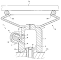
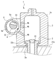
- the endoscope reproduction processing tool 1 includes a reflecting unit 6 disposed outside the direction changing unit 3.
- the reflection unit 6 includes a reflection surface 6 a that faces the plurality of holes 4 b provided in the discharge unit 4.
- the reflecting portion 6 is located at a position where the distal end portion 32 of the insertion portion 31 of the endoscope 30 positioned by the positioning portion 5 is disposed between the reflecting surface 6 a and the plurality of holes 4 b. Is provided.
- the shape of the reflective surface 6a is not limited to the concave shape as shown in FIG. 13, and may be a flat shape.
- the endoscope 30 has a configuration in which a concave portion 33 provided in the distal end portion 32 penetrates the distal end portion 32.
- the endoscope regeneration processing tool 1 of the present embodiment it is discharged from the plurality of holes 4b.
- the fluid flows in the concave portion 33 and hits the reflection surface 6a of the reflection portion 6 and flows along the outer peripheral surface of the tip end portion 32 opposite to the plurality of holes 4b.
- the fluid that has flowed into the recess 33 after being discharged from the plurality of holes 4 b can flow along the outer peripheral surface of the distal end portion 32 of the endoscope 30. Therefore, it is possible to perform the reproduction process with a focus on the outer peripheral surface of the distal end portion 32.
- fine irregularities may be provided on the reflecting surface 6a as in the modification of the present embodiment shown in FIG.
- the fluid discharged from the plurality of holes 4b flows so as to diffuse in various directions by hitting the reflecting surface 6a.
- the fluid that has flowed into the recess 33 after being discharged from the plurality of holes 4b is applied to the outer peripheral surface of the distal end portion 32 of the endoscope 30 without being biased. Can flow along.
- the endoscope reproduction processing tool 1 of the present embodiment is attached to and detached from the connector 25 provided on the bottom surface 21a of the processing tank 21 as in the first modification of the first embodiment shown in FIG. You may have the 2nd attachment / detachment part 2b. Further, in the endoscope regeneration processing tool 1 of the present embodiment, the connecting portion 2 is connected to the bottom surface 21a of the processing tank 21 as in the second or third modification of the first embodiment shown in FIGS. You may have the 3rd attachment / detachment part 2c or the 4th attachment / detachment part 2d which generate
- the endoscope regeneration processing tool 1 of the present embodiment is arranged on the bottom surface 21a of the processing tank 21 of the endoscope reprocessor 20 like the endoscope regeneration processing tool 1 of the second embodiment shown in FIG. It may be provided and mounted on a nozzle 27 that discharges fluid in a direction that intersects the direction of gravity.
- FIG. 15 shows an endoscope reproduction processing tool 1 according to the fourth embodiment.
- the endoscope reproduction processing tool 1 according to the fourth embodiment includes an entrance / exit 3b that is a through-hole penetrating from the outer surface of the direction changing portion 3 to an internal space, and a lid 7 that opens and closes the entrance / exit 3b.
- the lid 7 may be provided with a top surface cleaning hole 7 a that discharges fluid toward the inner surface of the lid 23 disposed above the processing tank 21.
- the internal space of the direction changing section 3 of the present embodiment has a volume that can accommodate one or a plurality of accessories 34 of the endoscope 30, and the entrance / exit 3 b is large enough to allow the accessories 34 to pass through. have.
- the kind and number of accessories 34 are not particularly limited.
- the accessory 34 is a cap that can be attached to and detached from the distal end portion 32 of the endoscope 30 and covers a part of the distal end portion 32.
- the accessory 34 may be a treatment instrument raising base removed from the distal end portion 32 of the endoscope 30 or a button removed from the endoscope 30.
- one or more accessories 34 are provided in the internal space of the direction changing unit 3. If stored, the accessory 34 can be regenerated using the fluid discharged from the fluid outlet 22.
- the endoscope reproduction processing tool 1 of the present embodiment is attached to and detached from the connector 25 provided on the bottom surface 21a of the processing tank 21 as in the first modification of the first embodiment shown in FIG. You may have the 2nd attachment / detachment part 2b. Further, in the endoscope regeneration processing tool 1 of the present embodiment, the connecting portion 2 is connected to the bottom surface 21a of the processing tank 21 as in the second or third modification of the first embodiment shown in FIGS. You may have the 3rd attachment / detachment part 2c or the 4th attachment / detachment part 2d which generate
- the endoscope regeneration processing tool 1 of the present embodiment is arranged on the bottom surface 21a of the processing tank 21 of the endoscope reprocessor 20 like the endoscope regeneration processing tool 1 of the second embodiment shown in FIG. It may be provided and mounted on a nozzle 27 that discharges fluid in a direction that intersects the direction of gravity.
- the endoscope regeneration processing tool 1 of the present embodiment is opposed to the plurality of holes 4b provided in the discharge section 4, like the endoscope regeneration processing tool 1 of the third embodiment shown in FIG.
- the reflective surface 6a may be provided.
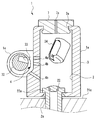
- FIG. 16 shows an endoscope reproduction processing tool 1 according to the fifth embodiment.
- the discharge unit 4 of the endoscope regeneration processing tool 1 according to the fifth embodiment includes a nozzle 4c that can change the discharge direction of the fluid to the direction of gravity.
- the nozzle 4c communicates with the internal space of the direction changing unit 3, and is attached to the direction changing unit 3 so as to rotate around a horizontal axis.
- the nozzle 4c protrudes from the outer surface of the direction changing portion 3.
- the tip of the nozzle 4c protruding from the outer surface of the direction changing portion 3 is inserted into a recess 33 provided in the tip 32 of the endoscope 30 positioned by the positioning portion 5, as shown in FIG. Is possible.
- the fluid used for the regeneration process is surely poured into the depth of the recess 33. It is possible.
- the nozzle 4c of this embodiment can change the discharge direction of the fluid to a gravity direction by rotating, the opening direction of the recessed part 33 of the front-end
- the endoscope reproduction processing tool 1 of the present embodiment is attached to and detached from the connector 25 provided on the bottom surface 21a of the processing tank 21 as in the first modification of the first embodiment shown in FIG. You may have the 2nd attachment / detachment part 2b. Further, in the endoscope regeneration processing tool 1 of the present embodiment, the connecting portion 2 is connected to the bottom surface 21a of the processing tank 21 as in the second or third modification of the first embodiment shown in FIGS. You may have the 3rd attachment / detachment part 2c or the 4th attachment / detachment part 2d which generate
- the endoscope regeneration processing tool 1 of the present embodiment is arranged on the bottom surface 21a of the processing tank 21 of the endoscope reprocessor 20 like the endoscope regeneration processing tool 1 of the second embodiment shown in FIG. It may be provided and mounted on a nozzle 27 that discharges fluid in a direction that intersects the direction of gravity.
- the endoscope regeneration processing tool 1 of the present embodiment is opposed to the plurality of holes 4b provided in the discharge section 4, like the endoscope regeneration processing tool 1 of the third embodiment shown in FIG.
- the reflective surface 6a may be provided.
- endoscope reproduction processing tool 1 of the present embodiment is similar to the endoscope reproduction processing tool 1 of the fourth embodiment shown in FIG.
- the accessory 34 may be accommodated.
- the present invention is not limited to the above-described embodiments, and can be appropriately changed without departing from the gist or concept of the invention that can be read from the claims and the entire specification.
- the processing tool is also included in the technical scope of the present invention.
Landscapes
- Health & Medical Sciences (AREA)
- Life Sciences & Earth Sciences (AREA)
- Surgery (AREA)
- Veterinary Medicine (AREA)
- Public Health (AREA)
- General Health & Medical Sciences (AREA)
- Animal Behavior & Ethology (AREA)
- Biomedical Technology (AREA)
- Pathology (AREA)
- Engineering & Computer Science (AREA)
- Nuclear Medicine, Radiotherapy & Molecular Imaging (AREA)
- Heart & Thoracic Surgery (AREA)
- Medical Informatics (AREA)
- Molecular Biology (AREA)
- Radiology & Medical Imaging (AREA)
- Optics & Photonics (AREA)
- Physics & Mathematics (AREA)
- Biophysics (AREA)
- Oral & Maxillofacial Surgery (AREA)
- Epidemiology (AREA)
- Endoscopes (AREA)
- Instruments For Viewing The Inside Of Hollow Bodies (AREA)
Abstract
La présente invention concerne un dispositif de retraitement d'endoscope comprenant : une section de connexion connectée à une ouverture de distribution de fluide ménagée dans la surface inférieure du réservoir de traitement d'un dispositif de retraitement d'endoscope ; une section de changement de direction servant à changer la direction d'écoulement du fluide, qui est déchargé à partir de l'ouverture de distribution de fluide, de la direction opposée à la direction de la gravité à une direction coupant la direction de la gravité ; une section de décharge servant à décharger le fluide, dont la direction d'écoulement a été modifiée par la section de changement de direction, dans une direction coupant la direction de la gravité ; et une section de positionnement servant à positionner l'extrémité distale de l'endoscope de telle sorte que la section de décharge et un évidement ménagé dans l'extrémité distale sont orientés l'un face à l'autre.
Priority Applications (3)
| Application Number | Priority Date | Filing Date | Title |
|---|---|---|---|
| JP2017537525A JP6219006B1 (ja) | 2016-04-25 | 2017-04-06 | 内視鏡再生処理具 |
| CN201780006278.1A CN108463158B (zh) | 2016-04-25 | 2017-04-06 | 内窥镜再生处理器具 |
| US16/031,313 US10588500B2 (en) | 2016-04-25 | 2018-07-10 | Endoscope reprocessing tool |
Applications Claiming Priority (2)
| Application Number | Priority Date | Filing Date | Title |
|---|---|---|---|
| JP2016087181 | 2016-04-25 | ||
| JP2016-087181 | 2016-04-25 |
Related Child Applications (1)
| Application Number | Title | Priority Date | Filing Date |
|---|---|---|---|
| US16/031,313 Continuation US10588500B2 (en) | 2016-04-25 | 2018-07-10 | Endoscope reprocessing tool |
Publications (1)
| Publication Number | Publication Date |
|---|---|
| WO2017187919A1 true WO2017187919A1 (fr) | 2017-11-02 |
Family
ID=60160440
Family Applications (1)
| Application Number | Title | Priority Date | Filing Date |
|---|---|---|---|
| PCT/JP2017/014312 Ceased WO2017187919A1 (fr) | 2016-04-25 | 2017-04-06 | Dispositif de retraitement d'endoscope |
Country Status (3)
| Country | Link |
|---|---|
| US (1) | US10588500B2 (fr) |
| CN (1) | CN108463158B (fr) |
| WO (1) | WO2017187919A1 (fr) |
Cited By (1)
| Publication number | Priority date | Publication date | Assignee | Title |
|---|---|---|---|---|
| IT201800003002A1 (it) * | 2018-02-23 | 2019-08-23 | Steelco Spa | Dispositivo di supporto per strumenti endoscopici da sottoporre a trattamento |
Citations (4)
| Publication number | Priority date | Publication date | Assignee | Title |
|---|---|---|---|---|
| EP0084342A2 (fr) * | 1982-01-19 | 1983-07-27 | Olympus Optical Co., Ltd. | Appareil de lavage |
| JPS58155834A (ja) * | 1982-03-11 | 1983-09-16 | オリンパス光学工業株式会社 | 内視鏡用洗浄装置 |
| US4862872A (en) * | 1987-04-17 | 1989-09-05 | Olympus Optical Co., Ltd. | Endoscope and endoscope washing apparatus |
| WO2015107801A1 (fr) * | 2014-01-15 | 2015-07-23 | オリンパスメディカルシステムズ株式会社 | Outil de lavage et dispositif de lavage/désinfection d'endoscope |
Family Cites Families (8)
| Publication number | Priority date | Publication date | Assignee | Title |
|---|---|---|---|---|
| JP2664148B2 (ja) | 1987-04-17 | 1997-10-15 | オリンパス光学工業株式会社 | 内視鏡装置 |
| JP2006246933A (ja) | 2005-03-08 | 2006-09-21 | Pentax Corp | 側方視型内視鏡の先端部 |
| US20060269442A1 (en) * | 2005-05-31 | 2006-11-30 | Nguyen Nick N | Endoscope reprocessor connectors having reduced occlusion |
| CN103269638B (zh) * | 2011-08-09 | 2015-11-25 | 奥林巴斯株式会社 | 内窥镜清洗消毒装置 |
| WO2014103880A1 (fr) * | 2012-12-26 | 2014-07-03 | オリンパスメディカルシステムズ株式会社 | Dispositif de lavage et de désinfection d'un endoscope |
| CN104661578B (zh) * | 2013-07-03 | 2016-08-17 | 奥林巴斯株式会社 | 内窥镜连接器具、连接器以及内窥镜清洗消毒装置 |
| JP6415913B2 (ja) | 2014-09-24 | 2018-10-31 | タカノ株式会社 | ライン照明装置及び外観検査システム |
| CN106455962B (zh) | 2014-10-15 | 2018-12-28 | 奥林巴斯株式会社 | 插入设备的清洗器具 |
-
2017
- 2017-04-06 WO PCT/JP2017/014312 patent/WO2017187919A1/fr not_active Ceased
- 2017-04-06 CN CN201780006278.1A patent/CN108463158B/zh active Active
-
2018
- 2018-07-10 US US16/031,313 patent/US10588500B2/en active Active
Patent Citations (4)
| Publication number | Priority date | Publication date | Assignee | Title |
|---|---|---|---|---|
| EP0084342A2 (fr) * | 1982-01-19 | 1983-07-27 | Olympus Optical Co., Ltd. | Appareil de lavage |
| JPS58155834A (ja) * | 1982-03-11 | 1983-09-16 | オリンパス光学工業株式会社 | 内視鏡用洗浄装置 |
| US4862872A (en) * | 1987-04-17 | 1989-09-05 | Olympus Optical Co., Ltd. | Endoscope and endoscope washing apparatus |
| WO2015107801A1 (fr) * | 2014-01-15 | 2015-07-23 | オリンパスメディカルシステムズ株式会社 | Outil de lavage et dispositif de lavage/désinfection d'endoscope |
Cited By (2)
| Publication number | Priority date | Publication date | Assignee | Title |
|---|---|---|---|---|
| IT201800003002A1 (it) * | 2018-02-23 | 2019-08-23 | Steelco Spa | Dispositivo di supporto per strumenti endoscopici da sottoporre a trattamento |
| WO2019162979A1 (fr) * | 2018-02-23 | 2019-08-29 | Steelco S.P.A. | Dispositif de support pour instruments endoscopiques à être soumis à un traitement |
Also Published As
| Publication number | Publication date |
|---|---|
| CN108463158B (zh) | 2020-06-19 |
| US20180317760A1 (en) | 2018-11-08 |
| CN108463158A (zh) | 2018-08-28 |
| US10588500B2 (en) | 2020-03-17 |
Similar Documents
| Publication | Publication Date | Title |
|---|---|---|
| JP6393855B2 (ja) | 洗浄器具及び内視鏡システム | |
| EP1815782A2 (fr) | Dispositif et procédé pour la déshydratation de canaux d'endoscope | |
| CN103269638B (zh) | 内窥镜清洗消毒装置 | |
| JP2003521325A (ja) | 制御された漏出を伴って再処理する内視鏡のための流体接続システム | |
| CN101053509A (zh) | 内窥镜洗涤消毒装置及用于洗涤内窥镜管路的刷单元 | |
| US20080271270A1 (en) | Probe cleaning tube | |
| JP5893817B1 (ja) | 濃度計及び内視鏡リプロセッサ | |
| EP3207860A1 (fr) | Accessoire de nettoyage de dispositif d'insertion | |
| CN104936501A (zh) | 内窥镜输送器具 | |
| WO2016194456A1 (fr) | Retraitement d'endoscope | |
| JP4723050B2 (ja) | 内視鏡洗浄具及び内視鏡洗浄装置 | |
| WO2017187919A1 (fr) | Dispositif de retraitement d'endoscope | |
| JP6219006B1 (ja) | 内視鏡再生処理具 | |
| JP2024547032A (ja) | 物体を滅菌/消毒装置内に保持するためのデバイス | |
| US20160270645A1 (en) | Concentration meter and endoscope reprocessor | |
| AU2008201322A1 (en) | Surgical instrument debris collection system | |
| US20070167810A1 (en) | Ultrasonic probe protection bracket and ultrasonic probe | |
| WO2021085075A1 (fr) | Dispositif de pulvérisation et dispositif de culture | |
| JP2018171255A (ja) | 内視鏡 | |
| JP2016214787A (ja) | 医療器具の浸漬用保持器 | |
| JP6013658B2 (ja) | 洗浄システム及び洗浄方法 | |
| JP2021153607A (ja) | 内視鏡リプロセッサ | |
| JP6905155B2 (ja) | 内視鏡リプロセッサおよびボトル | |
| WO2018168010A1 (fr) | Dispositif de retraitement d'endoscope | |
| CN211674136U (zh) | 内窥镜及其插入头端 |
Legal Events
| Date | Code | Title | Description |
|---|---|---|---|
| ENP | Entry into the national phase |
Ref document number: 2017537525 Country of ref document: JP Kind code of ref document: A |
|
| NENP | Non-entry into the national phase |
Ref country code: DE |
|
| 121 | Ep: the epo has been informed by wipo that ep was designated in this application |
Ref document number: 17789207 Country of ref document: EP Kind code of ref document: A1 |
|
| 122 | Ep: pct application non-entry in european phase |
Ref document number: 17789207 Country of ref document: EP Kind code of ref document: A1 |