WO2017187960A1 - Pneumatique - Google Patents
Pneumatique Download PDFInfo
- Publication number
- WO2017187960A1 WO2017187960A1 PCT/JP2017/014789 JP2017014789W WO2017187960A1 WO 2017187960 A1 WO2017187960 A1 WO 2017187960A1 JP 2017014789 W JP2017014789 W JP 2017014789W WO 2017187960 A1 WO2017187960 A1 WO 2017187960A1
- Authority
- WO
- WIPO (PCT)
- Prior art keywords
- groove
- tire
- land portion
- width direction
- platform
- Prior art date
- Legal status (The legal status is an assumption and is not a legal conclusion. Google has not performed a legal analysis and makes no representation as to the accuracy of the status listed.)
- Ceased
Links
Images

Classifications
-
- B—PERFORMING OPERATIONS; TRANSPORTING
- B60—VEHICLES IN GENERAL
- B60C—VEHICLE TYRES; TYRE INFLATION; TYRE CHANGING; CONNECTING VALVES TO INFLATABLE ELASTIC BODIES IN GENERAL; DEVICES OR ARRANGEMENTS RELATED TO TYRES
- B60C11/00—Tyre tread bands; Tread patterns; Anti-skid inserts
- B60C11/03—Tread patterns
- B60C11/12—Tread patterns characterised by the use of narrow slits or incisions, e.g. sipes
- B60C11/1236—Tread patterns characterised by the use of narrow slits or incisions, e.g. sipes with special arrangements in the tread pattern
- B60C11/125—Tread patterns characterised by the use of narrow slits or incisions, e.g. sipes with special arrangements in the tread pattern arranged at the groove bottom
-
- B—PERFORMING OPERATIONS; TRANSPORTING
- B60—VEHICLES IN GENERAL
- B60C—VEHICLE TYRES; TYRE INFLATION; TYRE CHANGING; CONNECTING VALVES TO INFLATABLE ELASTIC BODIES IN GENERAL; DEVICES OR ARRANGEMENTS RELATED TO TYRES
- B60C11/00—Tyre tread bands; Tread patterns; Anti-skid inserts
- B60C11/03—Tread patterns
-
- B—PERFORMING OPERATIONS; TRANSPORTING
- B60—VEHICLES IN GENERAL
- B60C—VEHICLE TYRES; TYRE INFLATION; TYRE CHANGING; CONNECTING VALVES TO INFLATABLE ELASTIC BODIES IN GENERAL; DEVICES OR ARRANGEMENTS RELATED TO TYRES
- B60C11/00—Tyre tread bands; Tread patterns; Anti-skid inserts
- B60C11/03—Tread patterns
- B60C11/0302—Tread patterns directional pattern, i.e. with main rolling direction
-
- B—PERFORMING OPERATIONS; TRANSPORTING
- B60—VEHICLES IN GENERAL
- B60C—VEHICLE TYRES; TYRE INFLATION; TYRE CHANGING; CONNECTING VALVES TO INFLATABLE ELASTIC BODIES IN GENERAL; DEVICES OR ARRANGEMENTS RELATED TO TYRES
- B60C11/00—Tyre tread bands; Tread patterns; Anti-skid inserts
- B60C11/03—Tread patterns
- B60C11/0306—Patterns comprising block rows or discontinuous ribs
- B60C11/0309—Patterns comprising block rows or discontinuous ribs further characterised by the groove cross-section
-
- B—PERFORMING OPERATIONS; TRANSPORTING
- B60—VEHICLES IN GENERAL
- B60C—VEHICLE TYRES; TYRE INFLATION; TYRE CHANGING; CONNECTING VALVES TO INFLATABLE ELASTIC BODIES IN GENERAL; DEVICES OR ARRANGEMENTS RELATED TO TYRES
- B60C11/00—Tyre tread bands; Tread patterns; Anti-skid inserts
- B60C11/03—Tread patterns
- B60C11/12—Tread patterns characterised by the use of narrow slits or incisions, e.g. sipes
-
- B—PERFORMING OPERATIONS; TRANSPORTING
- B60—VEHICLES IN GENERAL
- B60C—VEHICLE TYRES; TYRE INFLATION; TYRE CHANGING; CONNECTING VALVES TO INFLATABLE ELASTIC BODIES IN GENERAL; DEVICES OR ARRANGEMENTS RELATED TO TYRES
- B60C11/00—Tyre tread bands; Tread patterns; Anti-skid inserts
- B60C11/03—Tread patterns
- B60C11/13—Tread patterns characterised by the groove cross-section, e.g. for buttressing or preventing stone-trapping
-
- B—PERFORMING OPERATIONS; TRANSPORTING
- B60—VEHICLES IN GENERAL
- B60C—VEHICLE TYRES; TYRE INFLATION; TYRE CHANGING; CONNECTING VALVES TO INFLATABLE ELASTIC BODIES IN GENERAL; DEVICES OR ARRANGEMENTS RELATED TO TYRES
- B60C11/00—Tyre tread bands; Tread patterns; Anti-skid inserts
- B60C11/03—Tread patterns
- B60C11/13—Tread patterns characterised by the groove cross-section, e.g. for buttressing or preventing stone-trapping
- B60C11/1307—Tread patterns characterised by the groove cross-section, e.g. for buttressing or preventing stone-trapping with special features of the groove walls
- B60C11/1315—Tread patterns characterised by the groove cross-section, e.g. for buttressing or preventing stone-trapping with special features of the groove walls having variable inclination angles, e.g. warped groove walls
-
- B—PERFORMING OPERATIONS; TRANSPORTING
- B60—VEHICLES IN GENERAL
- B60C—VEHICLE TYRES; TYRE INFLATION; TYRE CHANGING; CONNECTING VALVES TO INFLATABLE ELASTIC BODIES IN GENERAL; DEVICES OR ARRANGEMENTS RELATED TO TYRES
- B60C11/00—Tyre tread bands; Tread patterns; Anti-skid inserts
- B60C11/03—Tread patterns
- B60C11/13—Tread patterns characterised by the groove cross-section, e.g. for buttressing or preventing stone-trapping
- B60C11/1353—Tread patterns characterised by the groove cross-section, e.g. for buttressing or preventing stone-trapping with special features of the groove bottom
-
- B—PERFORMING OPERATIONS; TRANSPORTING
- B60—VEHICLES IN GENERAL
- B60C—VEHICLE TYRES; TYRE INFLATION; TYRE CHANGING; CONNECTING VALVES TO INFLATABLE ELASTIC BODIES IN GENERAL; DEVICES OR ARRANGEMENTS RELATED TO TYRES
- B60C11/00—Tyre tread bands; Tread patterns; Anti-skid inserts
- B60C11/03—Tread patterns
- B60C11/13—Tread patterns characterised by the groove cross-section, e.g. for buttressing or preventing stone-trapping
- B60C11/1369—Tie bars for linking block elements and bridging the groove
-
- B—PERFORMING OPERATIONS; TRANSPORTING
- B60—VEHICLES IN GENERAL
- B60C—VEHICLE TYRES; TYRE INFLATION; TYRE CHANGING; CONNECTING VALVES TO INFLATABLE ELASTIC BODIES IN GENERAL; DEVICES OR ARRANGEMENTS RELATED TO TYRES
- B60C11/00—Tyre tread bands; Tread patterns; Anti-skid inserts
- B60C11/03—Tread patterns
- B60C2011/0337—Tread patterns characterised by particular design features of the pattern
- B60C2011/0339—Grooves
- B60C2011/0341—Circumferential grooves
-
- B—PERFORMING OPERATIONS; TRANSPORTING
- B60—VEHICLES IN GENERAL
- B60C—VEHICLE TYRES; TYRE INFLATION; TYRE CHANGING; CONNECTING VALVES TO INFLATABLE ELASTIC BODIES IN GENERAL; DEVICES OR ARRANGEMENTS RELATED TO TYRES
- B60C11/00—Tyre tread bands; Tread patterns; Anti-skid inserts
- B60C11/03—Tread patterns
- B60C2011/0337—Tread patterns characterised by particular design features of the pattern
- B60C2011/0339—Grooves
- B60C2011/0341—Circumferential grooves
- B60C2011/0351—Shallow grooves, i.e. having a depth of less than 50% of other grooves
-
- B—PERFORMING OPERATIONS; TRANSPORTING
- B60—VEHICLES IN GENERAL
- B60C—VEHICLE TYRES; TYRE INFLATION; TYRE CHANGING; CONNECTING VALVES TO INFLATABLE ELASTIC BODIES IN GENERAL; DEVICES OR ARRANGEMENTS RELATED TO TYRES
- B60C11/00—Tyre tread bands; Tread patterns; Anti-skid inserts
- B60C11/03—Tread patterns
- B60C2011/0337—Tread patterns characterised by particular design features of the pattern
- B60C2011/0339—Grooves
- B60C2011/0358—Lateral grooves, i.e. having an angle of 45 to 90 degees to the equatorial plane
- B60C2011/0362—Shallow grooves, i.e. having a depth of less than 50% of other grooves
-
- B—PERFORMING OPERATIONS; TRANSPORTING
- B60—VEHICLES IN GENERAL
- B60C—VEHICLE TYRES; TYRE INFLATION; TYRE CHANGING; CONNECTING VALVES TO INFLATABLE ELASTIC BODIES IN GENERAL; DEVICES OR ARRANGEMENTS RELATED TO TYRES
- B60C11/00—Tyre tread bands; Tread patterns; Anti-skid inserts
- B60C11/03—Tread patterns
- B60C11/13—Tread patterns characterised by the groove cross-section, e.g. for buttressing or preventing stone-trapping
- B60C11/1307—Tread patterns characterised by the groove cross-section, e.g. for buttressing or preventing stone-trapping with special features of the groove walls
- B60C2011/1338—Tread patterns characterised by the groove cross-section, e.g. for buttressing or preventing stone-trapping with special features of the groove walls comprising protrusions
-
- B—PERFORMING OPERATIONS; TRANSPORTING
- B60—VEHICLES IN GENERAL
- B60C—VEHICLE TYRES; TYRE INFLATION; TYRE CHANGING; CONNECTING VALVES TO INFLATABLE ELASTIC BODIES IN GENERAL; DEVICES OR ARRANGEMENTS RELATED TO TYRES
- B60C11/00—Tyre tread bands; Tread patterns; Anti-skid inserts
- B60C11/03—Tread patterns
- B60C11/13—Tread patterns characterised by the groove cross-section, e.g. for buttressing or preventing stone-trapping
- B60C11/1353—Tread patterns characterised by the groove cross-section, e.g. for buttressing or preventing stone-trapping with special features of the groove bottom
- B60C2011/1361—Tread patterns characterised by the groove cross-section, e.g. for buttressing or preventing stone-trapping with special features of the groove bottom with protrusions extending from the groove bottom
Definitions
- the present invention relates to a tire provided on a tread surface with a circumferential groove, a lug groove extending in a direction intersecting the circumferential groove, and a plurality of land portions defined by the circumferential groove and the lug groove.
- snow brake performance refers to the brake performance on a dry dry road surface.
- this width direction groove is made deep like a sipe, the rigidity of the land portion will be greatly reduced.
- the widthwise grooves are set shallow so as to prevent the deterioration of the dry brake performance and the wet brake performance while ensuring the rigidity of the land portion. For this reason, there was a problem that the snow performance obtained was not sufficient.
- This invention is made
- the tire according to the first aspect of the present invention is partitioned on the tread surface by a circumferential groove extending along the tire circumferential direction, a lug groove extending in a direction intersecting the circumferential groove, and the circumferential groove and the lug groove. And a plurality of land portions.
- a widthwise groove extending in the tire width direction is formed in the land portion.
- An in-groove sipe is arranged along one side edge at the groove bottom of the width direction groove.
- the tire according to the second aspect of the present invention is partitioned on the tread surface by a circumferential groove extending along the tire circumferential direction, a lug groove extending in a direction intersecting the circumferential groove, and the circumferential groove and the lug groove. And a platform provided on the groove side wall of the lug groove.
- the circumferential groove has a central circumferential groove and a lateral circumferential groove. As the land portion, a center-side land portion on the inner side in the tire width direction and a side-side land portion on the outer side in the tire width direction that are adjacent to each other in the tire width direction with the side-side circumferential groove interposed therebetween are arranged.
- the angle of inclination of the lug groove with respect to the tire width direction gradually decreases from the center side land portion to the side side land portion.
- the platform includes a central platform that is continuous on the inner side in the tire radial direction of the central side land portion, a lateral side circumferential groove platform that is continuous on the inner side in the tire radial direction of the lateral side circumferential groove, and a tire on the lateral side land portion. It is formed in a row by a side platform that is continuous radially inward. In the center side land portion and the side side land portion, the outer edge in the tire radial direction of the platform viewed from the lug groove side is shaped along the land portion tread.
- the tire according to the aspect of the present invention can improve the snow performance while ensuring the rigidity of the land portion.
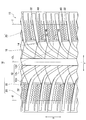
- FIG. 1 is a plan view showing a tread surface of a tire according to an embodiment of the present invention.
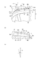
- 2A is a schematic enlarged plan view illustrating a tire platform according to an embodiment of the present invention
- FIG. 2B illustrates a tire platform according to an embodiment of the present invention.
- FIG. 2A is a schematic enlarged side view taken along the line IIb-IIb in FIG. 2A viewed from the lug groove side
- FIG. 2C is a schematic side view for explaining the inclination angle of the platform with respect to the tire radial direction. It is.
- FIG. 3A is a schematic enlarged perspective view illustrating a side land portion of a tire according to an embodiment of the present invention
- FIG. 3B is a side of the tire according to an embodiment of the present invention.
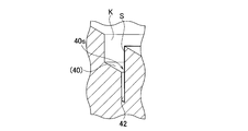
- FIG. 4 is a schematic cross-sectional view taken along line IIIb-IIIb in FIG. 3A, illustrating a side land portion, along a widthwise groove.
- FIG. 4 is a tire circumferential cross-sectional view illustrating a side land portion of a tire according to an embodiment of the present invention.
- the tire 10 described in the present embodiment is an optimal tire for use as a winter tire (particularly a lamellar tire).
- the tire 10 is partitioned on the tread surface by a circumferential groove 12 extending along the tire circumferential direction U, a lug groove 14 extending in a direction intersecting the circumferential groove 12, and the circumferential groove 12 and the lug groove 14.
- the circumferential groove 12 includes a circumferential main groove 12c (center side circumferential groove) through which the tire equator line CL passes, and a lateral side circumference located outside the circumferential main groove 12c in the tire width direction. And a directional groove 12d.
- the land portion 16 includes a central land portion 18 through which the circumferential main groove passes and a side land portion 20.
- the side side land portion 20 is a land portion on the outer side in the tire width direction with respect to the side side circumferential groove 12d.
- the circumferential groove 12 may be inclined with respect to the tire circumferential direction U, and the lug groove 14 may be inclined with respect to the tire width direction Y.
- the side circumferential grooves 12d are shallower than the circumferential main grooves 12c and the lug grooves 14, and the lug grooves 14 are shallower than the circumferential main grooves 12c.
- the lug groove 14 is curved and convex upward in FIG.
- the lug groove 14 has a gradually decreasing inclination angle ⁇ (see FIG. 2A) with respect to the tire width direction Y from the center side land portion 18 to the side side land portion 20.
- a platform 32 serving as a guideline for the use limit as a winter tire is provided on the groove side wall of the lug groove 14.
- the platform 32 includes a central side platform 19 that is continuous on the inner side in the tire radial direction of the central side land portion 18, a side side circumferential groove platform 13 that is continuous on the inner side in the tire radial direction of the side side circumferential groove 12d, and a side.
- the side land portion 20 is formed continuously with the side platform 21 that is continuous on the inner side in the tire radial direction.
- the tire radial direction outer edge 32 e of the platform 32 viewed from the lug groove side is formed along the land portion tread 16 s, and the lug groove 14 has a tire width direction.
- the inclination angle ⁇ with respect to Y decreases, the inclination angle ⁇ of the platform 32 with respect to the tire radial direction K (see FIG. 2C) increases.
- the tire radial direction height of the tire radial direction outer edge 32e of the platform 32 seen from the lug groove 14 side is the tire width from the platform starting point 32p which is the inner end in the tire width direction.
- the tire normal direction distance d with respect to the land tread 16s is a predetermined constant distance to the platform end point 32q which is the outer end in the direction, and the tire radial direction outer edge 32e is connected to the groove bottom 14b of the lug groove 14 at the platform end point 32q.
- the same height that is, the height from the groove bottom 14b is 0).
- the dimension W in the tire circumferential direction of the platform 32 in the tread view is a predetermined constant dimension from the platform end point 32q to the lateral circumferential groove 12d.
- the dimension W gradually decreases from the lateral side circumferential groove 12d to the inner side in the tire width direction, and is 0 at the platform start point 32p.
- the radius of curvature (curve shape) of the lug groove 14 (inclined main groove) varies greatly at the intersection 11 with the side circumferential groove 12d.
- the radius of curvature of the lug groove 14 gradually increases. And it can be said that the radius of curvature of the lug groove 14 is remarkably increased at the intersecting portion 11, and the inflection point G of the curved shape of the lug groove 14 exists on the intersecting portion 11.
- the lug groove 14 is drawing the curve near substantially linear form.
- the inclination angle with respect to the tire width direction Y of the lug groove wall 20s on the stepping end side of the side side land part 20 is the same position in the tire width direction Y.
- ⁇ may be smaller than an inclination angle ⁇ (see FIG. 2A) of the lug groove wall 20k on the kicking end side of the side land portion 20 with respect to the tire width direction Y.
- the shape of the platform 32 may be defined as follows.
- the position in the tire width direction where the platform 32 is disposed is a platform depression defined as a predetermined gauge thickness gauge equal to the first groove wall angle on the depression side of the side land portion 20 when viewed on the tread.
- the position of the intersection between the line segment of the groove wall angle on the side and the line segment of the second groove wall angle on the stepping side of the side land portion 20 is the platform start point, and is viewed from the side in the radial direction (that is, the lug groove 14 When viewed from the side), a predetermined distance from the tread shape, or a line segment defined as a predetermined concentric circle radially inward of the tread shape and a line segment at the bottom of the groove beyond the tread end T The position is defined as the platform end point.
- the height in the tire radial direction in which the platform 32 is disposed is a predetermined distance from the tread shape or the tread shape from the platform start point to the tread end T in the tire width direction when viewed from the side in the radial direction. Is a predetermined concentric circle radially inward and is 0 at the intersection of the tread end T and the line segment of the groove bottom.
- the circumferential width in the tread view where the platform 32 is arranged is such that the line segment of the first groove wall on the stepping side of the land portion and the stepping on the land portion from the platform end point position beyond the tread end T.
- the width is asymptotically from the inflection point G toward the inside in the tire width direction. Becomes smaller and becomes 0 at the platform start point.
- a width direction groove 40 (sub lug groove) extending in the tire width direction Y is formed in the side side land portion 20.
- an in-groove sipe 42 is disposed along one side edge of the groove bottom in a tread view.
- One end of the width direction groove 40 opens at the tread end T, and the other end does not open to the side-side circumferential groove 12d but ends at the end 40e.
- the in-groove sipe 42 is formed only along the side edge 40 s on the stepping side S of the width direction groove 40.
- the lateral side land portion 20 is divided into two land portion portions 20a and 20b adjacent to each other in the tire circumferential direction U by the width direction groove 40.
- the circumferential direction connection part 46 (refer FIG. 1, FIG. 3) which connects the two land part parts 20a and 20b is arrange
- the other end of the width direction groove 40 is configured to terminate 40e.
- the tire radial direction height of the circumferential connecting portion 46 is lower than the tread height of the side land portion 20.
- the first concave land portion 48 having the shallow groove 47 is formed across the two land portion portions 20a and 20b by the two land portion portions 20a and 20b and the circumferential connecting portion 46 positioned therebetween. Yes.
- the groove bottom 47 b of the shallow groove 47 is formed by the upper surface of the circumferential connecting portion 46.
- the lateral direction land portion 20 and the width direction coupling portion 56 that couples the central side land portion 18 adjacent to the tire width direction Y of the lateral side land portion 20 (FIG. 1, 3) is arranged.
- the height of the width direction connecting portion 56 (the height in the tire radial direction) is set lower than the height of the land portions 20a and 20b and the central land portion 18, and as a result, the second concave shape having the shallow groove 57 is formed.
- a land portion 58 is formed between the side land portion 20 and the central land portion 18.
- the groove bottom of the shallow groove 57 is formed by the upper surface of the width direction connecting portion 56.
- one or a plurality of sipes 60 along the width direction groove 40 are formed on the land portions 20a and 20b, respectively.
- the land portions 20a and 20b are depicted as an example in which one sipe 60 is formed.
- the sipe 60 is a sipe that extends in a zigzag shape.
- the groove bottom on the terminal end side (inner end in the tire width direction) of the width direction groove 40 is an inclined surface in which the groove depth gradually decreases toward the terminal end 40e.
- the groove bottom on the side opposite to the terminal end side is an inclined surface in which the groove depth gradually decreases toward the outer side in the tire width direction. Examples of the inclined surface include a tapered shape, a slope shape, and a convex shape.
- the snow performance can be improved by widening the width of the lug groove, which is a radial groove, but the individual land portion (hereinafter simply referred to as the land portion) becomes smaller, and the rigidity of the land portion is reduced. Since it becomes smaller and the dry brake performance and steering stability decline, a technique was adopted to ensure land rigidity by reinforcing the platform after widening the lug groove and to balance snow performance ( JP, 2011-183952, A). However, when the platform is placed on the land, the rigidity of the land is increased, and the dry brake performance and the handling stability are improved. However, since the volume of the groove is reduced, the snow performance is particularly deteriorated. There was a problem.
- the central platform 19 that is continuous with the inner side in the tire radial direction of the central side land portion 18 and the inner side in the tire radial direction of the lateral side circumferential groove 12d.
- a platform 32 is formed in which the lateral circumferential groove platform 13 that is continuous with the lateral platform 21 and the lateral platform 21 that is continuous on the inner side in the tire radial direction of the lateral land portion 20 are connected.
- the tire radial direction outer side edge 32e of the platform 32 seen from the lug groove side is made into the shape along the land part tread 16s.
- the platform portion formed in the lug groove portion having a small inclination angle ⁇ with respect to the tire width direction Y that is, the lug groove portion that is important in generating snow traction and snow braking.
- the inclination angle ⁇ with respect to the tire radial direction is large, large snow traction and snow braking can be generated.
- the platform 32 is formed so as to be continuous from the lateral platform 21 to the lateral circumferential groove platform 13 and further to the central platform 19. (That is, the effect of effectively improving snow performance while maintaining the rigidity of the land portion) has been obtained considerably.
- the tire radial direction height of the tire radial direction outer edge 32e of the platform 32 seen from the lug groove 14 side is the land from the platform start point 32p which is the inner end in the tire width direction to the platform end point 32q which is the outer end in the tire width direction.
- the tire normal direction distance d with respect to the tread surface 16s is a height that is a predetermined constant distance, and the tire radial direction outer edge 32e is the same height as the groove bottom 14b of the lug groove 14 at the platform end point 32q.
- the snow column shear force and the edge effect by the lug groove portion from the tire radial direction outer edge 32e to the land tread surface 16s can be uniformly performed over the entire length of the platform 32 over the entire length of the platform 32.
- the dimension W in the tire circumferential direction of the platform 32 in the tread view is a predetermined constant dimension from the platform end point 32q to the lateral side circumferential groove 12d, and the dimension from the lateral side circumferential groove 12d to the inner side in the tire width direction. W gradually decreases and is 0 at the platform start point 32p.
- the inner side in the tire width direction from the lateral side circumferential groove 12d is a lug groove portion where the inclination angle ⁇ of the lug groove 14 with respect to the tire width direction Y gradually increases, and the platform 32 gradually increases in such lug groove portion. Can be converged.
- the sipe edge component increases.
- the land portion rigidity is lowered, the wear resistance performance is lowered.
- the land portion rigidity is lowered and the land portion deformation becomes too large, the land portion is greatly collapsed and the edge effect is also lowered.
- the influence is large on the shoulder side where a large input is made in the circumferential direction.
- the in-groove sipe 42 is disposed along the one side edge of the groove bottom 14 b of the width direction groove 40 in the width direction groove 40 formed in the lateral side land portion 20. .
- the widthwise groove 40 is easily expanded by the amount of the in-groove sipe 42 as compared with the case where the in-groove sipe 42 is not formed. So open wide. Therefore, a lot of snow can be scraped by the edge of the wide groove 40 which is wide open, so the edge effect is increased. In addition, a large amount of snow can be taken in and hardened at the time of ground contact, and the snow column shear force discharged when the ground contact is released can be increased.
- the in-groove sipe 42 Even if it adds, the rigidity of the side side land part 20 does not fall.
- the sipe 42 in the groove is stepped on the width direction groove 40 on the kick side on the rear side of the width direction groove 40 of the side land portion 20, that is, the lug groove wall portion that exhibits the edge effect in the width direction groove 40 when the land portion is stepped on. Since it is at the end of the side, the rigidity of the side land portion 20 is hardly lowered, and even if a sipe is added, the edge effect of the width direction groove 40 at the time of depression can be maintained without being lowered.
- the in-groove sipe 42 is disposed in the width direction groove 40 along one side edge on the land portion stepping end side so that the rigidity in the compression direction on the land portion stepping end side can be secured during braking.
- the width direction groove 40 is greatly opened without lowering the rigidity of the land portion, and the edge effect and the snow column shearing force effect are increased to further improve the snow performance, and the dry brake performance and the wet brake performance are not deteriorated. It is possible to reconcile performance that has been contradictory until now.
- one side edge of the groove bottom 14b is the side edge 40s of the stepping side S, and the in-groove sipe 42 is provided only along the side edge 40s of the stepping side S. Thereby, the effect obtained by the in-groove sipe 42 becomes more remarkable.
- maintaining the rigidity of the land portion without lowering it can maintain all the wet, dry brake performance, wet, dry driving performance, and wear performance without lowering.
- the position of the in-groove sipe in the width direction groove 40 is the force in the compression direction at the land kicking end side. It is desirable that the land sipe 42 is closed to ensure rigidity by closing the sipe 42 in the groove.
- one end of the width direction groove 40 opens to the tread end T, and the other end terminates without opening to the side circumferential groove 12d. Therefore, the tire circumferential direction rigidity of the lateral side land portion 20 can be lowered by opening at one end, and the water that has entered the width direction groove 40 can be easily drained. And by making it terminate at the other end, the tire circumferential direction rigidity of the lateral side land portion 20 can be increased, and the land portion rigidity can be suppressed from being excessively lowered.
- width direction groove 40 is not opened in the side side circumferential groove 12d, water does not flow from the side side circumferential groove 12d into the width direction groove 40, and the side side circumferential groove 40 It is possible to efficiently prevent the turbulent flow generated in 12d and the drainage performance of the widthwise grooves 40 and the lateral side circumferential grooves 12d from being deteriorated.
- sipes 60 are arranged on the front and rear land portions 20 a and 20 b in the tire circumferential direction U, and the width direction groove 40 is arranged in the center of the land portion in the tire circumferential direction U.
- the width direction groove 40 is not disposed in any part other than the land part center part (land part circumferential direction end part).
- the groove bottom on the terminal end side of the widthwise groove 40 has an inclined surface in which the groove depth gradually decreases toward the terminal end 40e, and is opposite to the terminal end side of the widthwise groove 40.
- the groove bottom has an inclined surface in which the groove depth gradually decreases toward the outer side in the tire width direction. Examples of the inclined surface include a tapered shape, a slope shape, and a convex shape.
- the rigidity of the land portion is locally reduced to prevent a rigidity step from occurring between the end 40e of the widthwise groove 40 and the tread end T, and the unevenness of the land portion rigidity in the tire width direction Y is prevented. Can be suppressed. In addition, the effect becomes more remarkable by making an inclined surface into a slope shape.
- the inclination angle ⁇ of the step-side lug groove wall 20s of the side land portion 20 with respect to the tire width direction Y is the inclination angle of the kick side lug groove wall 20k of the side land portion 20 with respect to the tire width direction Y. Larger than ⁇ .
- the inclination angle is the same on both the stepping-in side and the kicking-out side, but in this embodiment, the groove volume (groove volume) is increased by cutting the groove wall in order to improve drainage.
- the water in the lug groove 14 is drained toward the tread end T located on the outer side in the tire width direction. Therefore, in this embodiment, the groove volume is effectively reduced by cutting the groove wall on the kicking side, which has less influence even if the groove wall is cut, while maintaining the gentle inclined wall surface on the stepping side where water hits most without being cut. Can be increased.
- the width direction groove 40 has been described with an example in which one end is opened to the tread end T and the other end is terminated without opening to the side circumferential groove 12d. It is also possible to adopt a configuration that opens to the side-side circumferential groove 12d and that the other end terminates without opening to the tread end T. In this case, the circumferential direction connection part 46 is arrange
- Example 1 As can be seen from Table 1, in Example 1, the dry brake performance can be maintained to some extent, and the snow performance can be sufficiently increased.
- the tire according to the embodiment of the present invention can improve snow performance while ensuring the rigidity of the land portion.
Landscapes
- Engineering & Computer Science (AREA)
- Mechanical Engineering (AREA)
- Tires In General (AREA)
Abstract
Priority Applications (4)
| Application Number | Priority Date | Filing Date | Title |
|---|---|---|---|
| EP17789247.8A EP3450215B1 (fr) | 2016-04-28 | 2017-04-11 | Pneumatique |
| US16/096,451 US11390122B2 (en) | 2016-04-28 | 2017-04-11 | Tire |
| CN201780026283.9A CN109153292B (zh) | 2016-04-28 | 2017-04-11 | 轮胎 |
| JP2018514244A JP6850795B2 (ja) | 2016-04-28 | 2017-04-11 | タイヤ |
Applications Claiming Priority (4)
| Application Number | Priority Date | Filing Date | Title |
|---|---|---|---|
| JP2016-091321 | 2016-04-28 | ||
| JP2016091321 | 2016-04-28 | ||
| JP2016091326 | 2016-04-28 | ||
| JP2016-091326 | 2016-04-28 |
Publications (1)
| Publication Number | Publication Date |
|---|---|
| WO2017187960A1 true WO2017187960A1 (fr) | 2017-11-02 |
Family
ID=60160508
Family Applications (1)
| Application Number | Title | Priority Date | Filing Date |
|---|---|---|---|
| PCT/JP2017/014789 Ceased WO2017187960A1 (fr) | 2016-04-28 | 2017-04-11 | Pneumatique |
Country Status (5)
| Country | Link |
|---|---|
| US (1) | US11390122B2 (fr) |
| EP (1) | EP3450215B1 (fr) |
| JP (1) | JP6850795B2 (fr) |
| CN (1) | CN109153292B (fr) |
| WO (1) | WO2017187960A1 (fr) |
Cited By (3)
| Publication number | Priority date | Publication date | Assignee | Title |
|---|---|---|---|---|
| WO2020078742A1 (fr) * | 2018-10-16 | 2020-04-23 | Bridgestone Europe Nv/Sa | Bande de roulement pour enveloppe pneumatique d'hiver, et enveloppe pneumatique d'hiver |
| JP2021511254A (ja) * | 2018-01-28 | 2021-05-06 | コンパニー ゼネラール デ エタブリッスマン ミシュラン | 空気タイヤ |
| EP4019284A1 (fr) * | 2020-12-28 | 2022-06-29 | Toyo Tire Corporation | Pneumatique |
Families Citing this family (2)
| Publication number | Priority date | Publication date | Assignee | Title |
|---|---|---|---|---|
| JP7372550B2 (ja) * | 2020-04-14 | 2023-11-01 | 横浜ゴム株式会社 | タイヤ |
| JP2024094511A (ja) * | 2022-12-28 | 2024-07-10 | Toyo Tire株式会社 | 空気入りタイヤ |
Citations (9)
| Publication number | Priority date | Publication date | Assignee | Title |
|---|---|---|---|---|
| JPH11139114A (ja) * | 1997-11-14 | 1999-05-25 | Yokohama Rubber Co Ltd:The | 氷雪路用空気入りタイヤ |
| JP2002029221A (ja) * | 2000-07-12 | 2002-01-29 | Bridgestone Corp | 空気入りタイヤ |
| JP2003063212A (ja) * | 2001-08-23 | 2003-03-05 | Bridgestone Corp | 空気入りタイヤ |
| JP2006213175A (ja) * | 2005-02-03 | 2006-08-17 | Bridgestone Corp | 空気入りタイヤ |
| JP2007062691A (ja) * | 2005-09-02 | 2007-03-15 | Yokohama Rubber Co Ltd:The | 空気入りタイヤ |
| EP2322359A1 (fr) * | 2009-11-16 | 2011-05-18 | Continental Reifen Deutschland GmbH | Profil de bande de roulement d'un pneu de véhicule |
| JP2012035686A (ja) * | 2010-08-05 | 2012-02-23 | Bridgestone Corp | 空気入りタイヤ |
| JP2012076684A (ja) * | 2010-10-05 | 2012-04-19 | Bridgestone Corp | タイヤ |
| JP2016055817A (ja) * | 2014-09-11 | 2016-04-21 | 横浜ゴム株式会社 | 空気入りタイヤ |
Family Cites Families (13)
| Publication number | Priority date | Publication date | Assignee | Title |
|---|---|---|---|---|
| JP3136101B2 (ja) | 1996-09-19 | 2001-02-19 | 住友ゴム工業株式会社 | 空気入りタイヤ |
| US7341083B2 (en) * | 2001-12-26 | 2008-03-11 | Bridgestone Corporation | Pneumatic radial tire with tread having blocks provided with sipes |
| EP1566291B1 (fr) | 2002-11-06 | 2011-07-20 | Bridgestone Corporation | Pneumatique |
| JP5160870B2 (ja) | 2007-12-10 | 2013-03-13 | 東洋ゴム工業株式会社 | 空気入りタイヤ |
| DE102009044553A1 (de) * | 2009-11-16 | 2011-05-19 | Continental Reifen Deutschland Gmbh | Laufstreifenprofil eines Fahrzeugreifens |
| JP5356285B2 (ja) | 2010-03-09 | 2013-12-04 | 東洋ゴム工業株式会社 | 空気入りタイヤ |
| DE102010016978A1 (de) | 2010-05-18 | 2011-11-24 | Continental Reifen Deutschland Gmbh | Fahrzeugluftreifen |
| JP5437197B2 (ja) | 2010-08-12 | 2014-03-12 | 株式会社ブリヂストン | 空気入りタイヤ |
| EP2610083B1 (fr) | 2010-08-25 | 2015-10-07 | Bridgestone Corporation | Pneu |
| FR2964344B1 (fr) | 2010-09-02 | 2012-08-31 | Michelin Soc Tech | Bandage pneumatique avec une bande de roulement comportant un materiau de remplissage degradable |
| DE102010060946A1 (de) * | 2010-12-01 | 2012-06-06 | Continental Reifen Deutschland Gmbh | Fahrzeugluftreifen |
| DE112013006724T5 (de) * | 2013-02-22 | 2015-11-19 | The Yokohama Rubber Co., Ltd. | Luftreifen |
| JP2015009775A (ja) | 2013-07-02 | 2015-01-19 | 横浜ゴム株式会社 | 空気入りタイヤ |
-
2017
- 2017-04-11 WO PCT/JP2017/014789 patent/WO2017187960A1/fr not_active Ceased
- 2017-04-11 JP JP2018514244A patent/JP6850795B2/ja active Active
- 2017-04-11 US US16/096,451 patent/US11390122B2/en active Active
- 2017-04-11 EP EP17789247.8A patent/EP3450215B1/fr active Active
- 2017-04-11 CN CN201780026283.9A patent/CN109153292B/zh active Active
Patent Citations (9)
| Publication number | Priority date | Publication date | Assignee | Title |
|---|---|---|---|---|
| JPH11139114A (ja) * | 1997-11-14 | 1999-05-25 | Yokohama Rubber Co Ltd:The | 氷雪路用空気入りタイヤ |
| JP2002029221A (ja) * | 2000-07-12 | 2002-01-29 | Bridgestone Corp | 空気入りタイヤ |
| JP2003063212A (ja) * | 2001-08-23 | 2003-03-05 | Bridgestone Corp | 空気入りタイヤ |
| JP2006213175A (ja) * | 2005-02-03 | 2006-08-17 | Bridgestone Corp | 空気入りタイヤ |
| JP2007062691A (ja) * | 2005-09-02 | 2007-03-15 | Yokohama Rubber Co Ltd:The | 空気入りタイヤ |
| EP2322359A1 (fr) * | 2009-11-16 | 2011-05-18 | Continental Reifen Deutschland GmbH | Profil de bande de roulement d'un pneu de véhicule |
| JP2012035686A (ja) * | 2010-08-05 | 2012-02-23 | Bridgestone Corp | 空気入りタイヤ |
| JP2012076684A (ja) * | 2010-10-05 | 2012-04-19 | Bridgestone Corp | タイヤ |
| JP2016055817A (ja) * | 2014-09-11 | 2016-04-21 | 横浜ゴム株式会社 | 空気入りタイヤ |
Cited By (7)
| Publication number | Priority date | Publication date | Assignee | Title |
|---|---|---|---|---|
| JP2021511254A (ja) * | 2018-01-28 | 2021-05-06 | コンパニー ゼネラール デ エタブリッスマン ミシュラン | 空気タイヤ |
| JP7273833B2 (ja) | 2018-01-28 | 2023-05-15 | コンパニー ゼネラール デ エタブリッスマン ミシュラン | 空気タイヤ |
| WO2020078742A1 (fr) * | 2018-10-16 | 2020-04-23 | Bridgestone Europe Nv/Sa | Bande de roulement pour enveloppe pneumatique d'hiver, et enveloppe pneumatique d'hiver |
| CN112888581A (zh) * | 2018-10-16 | 2021-06-01 | 普利司通欧洲有限公司 | 冬季充气轮胎用胎面以及冬季充气轮胎 |
| US20210347207A1 (en) * | 2018-10-16 | 2021-11-11 | Bridgestone Europe Nv/Sa | Tread for a Winter Pneumatic Tire and a Winter Pneumatic Tire |
| US12257860B2 (en) | 2018-10-16 | 2025-03-25 | Bridgestone Europe Nv/Sa | Tread for a winter pneumatic tire and a winter pneumatic tire |
| EP4019284A1 (fr) * | 2020-12-28 | 2022-06-29 | Toyo Tire Corporation | Pneumatique |
Also Published As
| Publication number | Publication date |
|---|---|
| EP3450215A1 (fr) | 2019-03-06 |
| JP6850795B2 (ja) | 2021-03-31 |
| EP3450215A4 (fr) | 2019-04-24 |
| US20190126690A1 (en) | 2019-05-02 |
| CN109153292B (zh) | 2020-11-10 |
| US11390122B2 (en) | 2022-07-19 |
| CN109153292A (zh) | 2019-01-04 |
| JPWO2017187960A1 (ja) | 2019-03-07 |
| EP3450215B1 (fr) | 2020-05-13 |
Similar Documents
| Publication | Publication Date | Title |
|---|---|---|
| JP4580387B2 (ja) | 空気入りタイヤ | |
| JP6164235B2 (ja) | 空気入りタイヤ | |
| JP6142930B1 (ja) | 空気入りタイヤ | |
| JP6065033B2 (ja) | 空気入りタイヤ | |
| AU2014388518B2 (en) | Pneumatic tire | |
| CN101168341B (zh) | 充气轮胎 | |
| WO2017187960A1 (fr) | Pneumatique | |
| KR20130086975A (ko) | 공기 타이어 | |
| CN105579252B (zh) | 不平整地面行驶用的摩托车用轮胎 | |
| CN102149548A (zh) | 具有可变表面面积的轮胎胎面和轮胎 | |
| CN105899376A (zh) | 充气轮胎 | |
| CN106163830A (zh) | 在胎面的边缘上具有通道的胎面 | |
| US8302644B2 (en) | Pneumatic tire with tread having series of depressions in rib | |
| CN112689566A (zh) | 充气轮胎 | |
| WO2018225371A1 (fr) | Pneumatique | |
| JP5639461B2 (ja) | 空気入りタイヤ | |
| WO2017082414A1 (fr) | Pneu | |
| CN113508041B (zh) | 具有带盲微纹沟的周向纹沟的卡车轮胎 | |
| CN104908526B (zh) | 充气轮胎 | |
| CN104822544B (zh) | 充气轮胎 | |
| JP5698622B2 (ja) | タイヤ | |
| JP2002274125A (ja) | 空気入りタイヤ | |
| CN108602393A (zh) | 充气轮胎 | |
| JP6571993B2 (ja) | 空気入りタイヤ | |
| CN110385945B (zh) | 轮胎 |
Legal Events
| Date | Code | Title | Description |
|---|---|---|---|
| ENP | Entry into the national phase |
Ref document number: 2018514244 Country of ref document: JP Kind code of ref document: A |
|
| NENP | Non-entry into the national phase |
Ref country code: DE |
|
| 121 | Ep: the epo has been informed by wipo that ep was designated in this application |
Ref document number: 17789247 Country of ref document: EP Kind code of ref document: A1 |
|
| WWE | Wipo information: entry into national phase |
Ref document number: 2017789247 Country of ref document: EP |
|
| ENP | Entry into the national phase |
Ref document number: 2017789247 Country of ref document: EP Effective date: 20181128 |